Article

Investigation of the Effectiveness of a Compact Heat Exchanger with Metal Foam in Supercritical Carbon Dioxide Cooling

Department of Process and Environmental Engineering, Faculty of Mechanical Engineering, Opole University of Technology, Mikolajczyka 5, 45-271 Opole, Poland
Energies 2025, 18(17), 4736; https://doi.org/10.3390/en18174736
Submission received: 30 July 2025 / Revised: 31 August 2025 / Accepted: 3 September 2025 / Published: 5 September 2025
(This article belongs to the Section J1: Heat and Mass Transfer)

Abstract

Printed circuit heat exchangers (PCHE) are ideal for use in very demanding operating conditions. In addition, they are characterized by very high efficiency, which can still be increased. This paper presents new concepts for improving PCHE heat exchangers. The aim of the described work was to evaluate the potential for improving the performance of printed circuit heat exchangers by incorporating open-cell metal foam as the heat exchanger packing material. The evaluation was conducted based on the results of numerical simulation of supercritical carbon dioxide cooling flowing through printed circuit heat exchanger channels filled with 40 PPI copper foam with 90% porosity. A unit periodic region of the heat exchanger comprising two adjacent straight channels for cold and hot fluid was analyzed. The channels had a semicircular cross-section and a length of 200 mm. Studies were conducted for three different channel diameters—2, 3, and 4 mm. The range of mass flux variations for cold fluid (water) and hot fluid (sCO2) were 300–1500 kg/(m2·s) and 200–800 kg/(m2·s), respectively. It was found that in channels filled with metal foam, carbon dioxide cooling is characterized by a higher heat transfer coefficient than in channels without metal foam. In channels of the same diameter, heat flux was 33–63% higher in favor of the channel with metal foam. Thermal effectiveness of the heat exchanger with metal foam can be up to 20% higher than in the case of a heat exchanger without foam. Despite very high pressure drop through channels filled with metal foam, thermal–hydraulic performance can also be higher—even 4.7 in the case of a 2 mm channel. However, both these parameters depend on flow conditions and channel diameter, and under certain conditions may be lower than in a heat exchanger without metal foam. The results of the presented work indicate a new direction for the development of PCHE heat exchangers and confirm that the use of metal foams in the construction of PCHE heat exchangers can contribute to increasing the efficiency and effectiveness of the processes in which they are used.

1. Introduction

Limited energy resources necessitate efforts to increase the efficiency of energy production and conversion processes and maximize energy recovery. These processes are often carried out under extremely difficult conditions—at pressures of hundreds of bars and very high or low temperatures, ranging from cryogenic temperatures of around −250 °C (for liquid hydrogen) to temperatures exceeding 900 °C, typical for nuclear power and catalytic processes. The implementation of technological processes in conditions so different from the environment requires the use of various types of heat exchangers.
In industrial practice, many types of heat exchangers with different designs, capacities, and efficiencies are used. A significant proportion of classic heat exchangers, even if they are characterized by high energy efficiency and favorable operating characteristics, are not structurally adapted to operate at pressures of hundreds of bars. In this respect, printed circuit heat exchangers (PCHE) have particularly advantageous features. Their monoblock design and small flow channel dimensions give them the ability to transfer very high fluid pressure, regardless of temperature. In addition, these exchangers have a very high heat exchange surface-area-to-volume ratio, reaching up to 2500 m2/m3 [1]. The resulting heat exchangers demonstrate remarkable compactness, achieving up to 85% volume reduction compared to traditional shell-and-tube exchangers, making them indispensable for applications with stringent space constraints. PCHEs have found extensive application across diverse energy systems where they serve critical roles in improving energy efficiency. In supercritical carbon dioxide (sCO2) Brayton cycles, PCHEs function as both recuperators and precoolers, accounting for approximately 80% of total expenditure in sCO2 power cycles. They are essential in advanced power generation systems and Concentrated Solar Power (CSP) facilities, where high heat transfer coefficients near the critical region substantially boost power cycle performance while reducing component size. In the LNG sector, PCHEs serve as critical vaporizers in Floating Storage and Regasification Units (FSRUs), handling transcritical fluids under challenging marine conditions. The hydrogen energy sector utilizes PCHEs in refueling stations for efficient precooling systems, while nuclear reactors employ them as intermediate heat exchangers. Additional applications include condensers in cryogenic CO2 capture systems and components in Liquid Air Energy Storage (LAES) systems.

1.1. Background on Heat Exchanger Research

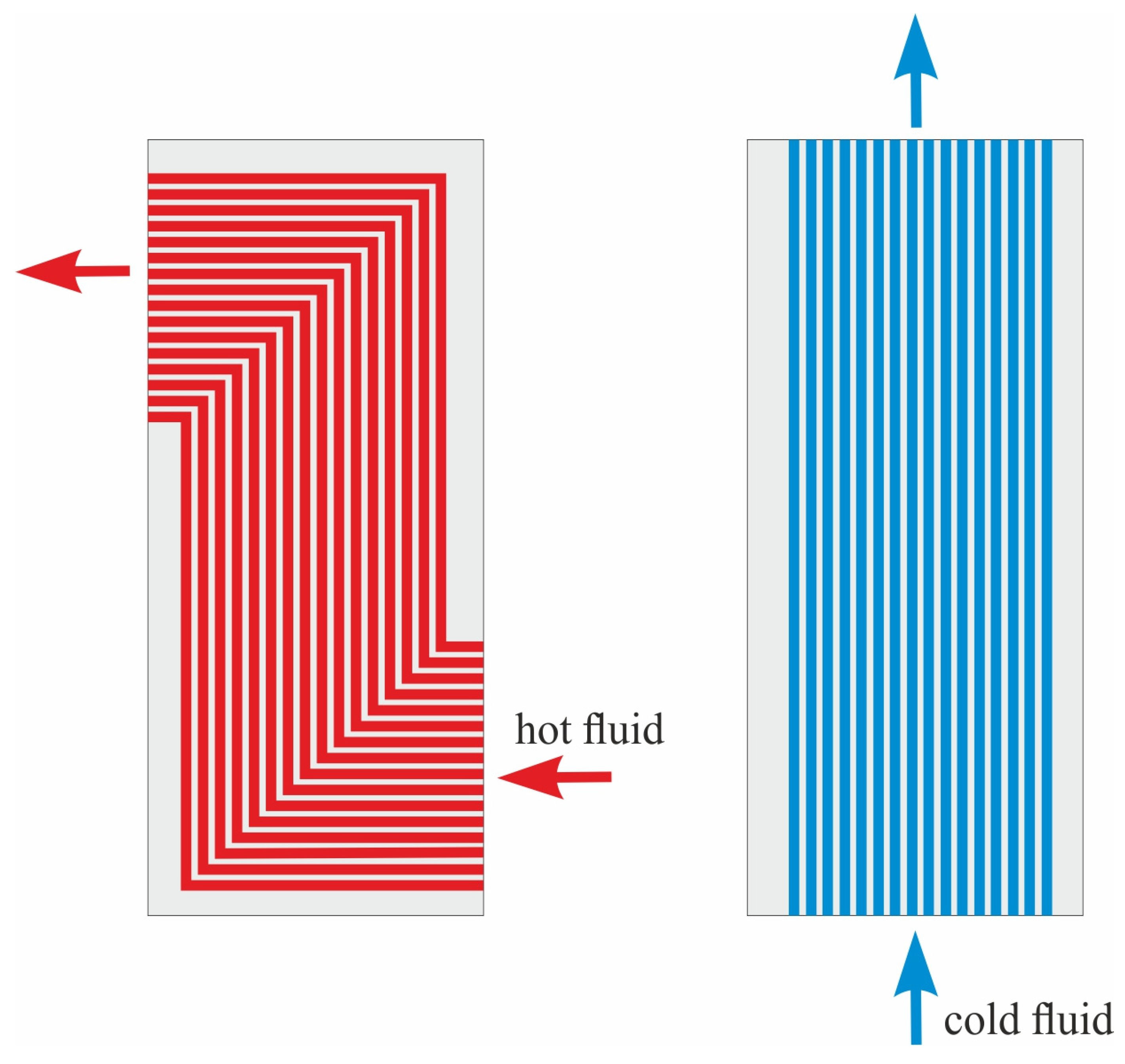
In standard design, the main part of a printed circuit heat exchanger takes the form of a monolithic core, which is created by diffusion welding of a stack of many flat metal plates. Before welding, channels are etched on the surface of each plate. After connecting the plates in the heat exchanger core, flow channels for hot and cold fluid are created, arranged in periodic layers (Figure 1).
The cross-section of channels is most often semicircular or similar to this shape. The channel configuration can vary (Figure 2). Most commonly these are straight, wavy, or zigzag-type channels.
Regardless of the channel type, one of the fluids is usually supplied to the front surface of the heat exchanger core and flows out from the opposite side of the core. The second fluid is supplied to the lateral surface of the core (Figure 3). Near the inlets and outlets, fluid flow occurs crosswise, while in the central part of the heat exchanger, fluids flow parallel to each other.
Printed circuit heat exchangers are being intensively researched for various applications, including supercritical carbon dioxide (sCO2) Brayton cycles, liquefied natural gas (LNG) systems, hydrogen refueling stations, and nuclear reactor applications.
Much of the studies focus on the application and optimization of PCHEs as recuperators and precoolers in supercritical carbon dioxide (sCO2) Brayton cycles, particularly for advanced power generation and Concentrated Solar Power (CSP) systems. Ahmed and Ehsan [2] and Baik et al. [3] addressed critical gaps in understanding thermo-hydraulic performance of zigzag PCHEs under precooler conditions in indirect cooling systems for sCO2 recompression cycles. Their research incorporated the abrupt changes in sCO2 thermo-physical characteristics near the critical region, validating design codes against previous CFD-aided designs and experimental data. Cheng et al. [4] provided empirical validation through experimental investigation of PCHEs used as precoolers for supercritical CO2 Brayton cycles, contributing essential thermal–hydraulic characteristic data.
The thermal–hydraulic performance of PCHEs is intrinsically linked to channel design, with continuous research focusing on optimizing various configurations. Table 1 presents the conditions for conducting research in this area. Zigzag channels enhance heat transfer by promoting turbulent flow but increase pressure drop, while S-shaped and airfoil channels reduce flow resistance while maintaining superior heat transfer performance. Jin et al. [5] conducted a comprehensive numerical comparison of zigzag, wavy, and airfoil fins PCHEs under sCO2 precooler conditions, demonstrating that zigzag channels exhibit superior heat transfer performance, particularly near the pseudo-critical region, while airfoil channels demonstrate lower friction factors. The development of accurate heat transfer correlations for sCO2 in PCHEs has been a significant research focus. Jin et al. [6] presented experimental studies on cooling heat transfer performance of supercritical CO2 in zigzag PCHEs, analyzing the effects of system pressure, inlet temperature, and mass flux. They proposed new cooling heat transfer correlations to improve prediction accuracy, noting that existing correlations often underestimate performance in zigzag channels. Li et al. [7] developed a PDF-based semi-empirical correlation for forced convection heat transfer of sCO2 within PCHEs, accounting for instantaneous turbulent temperature and fluctuating properties near the critical point. Their work demonstrated that heat transfer coefficients near the pseudo-critical point are significantly higher in cooling mode than in heating mode.
Design optimization for enhanced performance has been extensively studied. Han et al. [11] proposed rib structures on the top flat wall of semicircular–straight channels for high-power sCO2 Brayton cycle systems based on Concentrated Solar Power (CSP). The addition of rib structures significantly increased turbulence kinetic energy and enhanced heat transfer, resulting in a 15.3% increase in system efficiency and a 3.8% improvement in compactness. Khoshvaght-Aliabadi et al. [14] demonstrated through 3D simulations that replacing straight mini-channels with wavy configurations can enhance thermal performance by an average of 1.86 times, primarily due to larger wave amplitudes and smaller wavelengths, especially at lower inlet temperatures near the pseudocritical point. System-level studies have highlighted the critical role of PCHEs in overall cycle performance. Moisseytsev et al. [15] analyzed performance improvement options for sCO2 Brayton cycles using Advanced Burner Test Reactor (ABTR) conditions as reference, identifying the recuperator as the component with the largest volume and heat capacity, emphasizing its critical role in cycle economics and plant footprint reduction. Ren et al. [10] established an experimental system to investigate rectangular microchannel PCHE performance using sCO2 and cooling water, finding that sCO2 inlet temperature has the most significant effect on heat transfer performance, with maximum heat transfer efficiency reaching 96.9%. Research on CO2/propane mixtures has shown promising results for stable operation and economic benefits. Zhou et al. [12,16] conducted numerical studies investigating thermal–hydraulic characteristics of CO2 and CO2/propane mixtures in both wavy and straight-channel PCHEs for regenerator applications, proposing correlations for Nusselt number and friction factors that demonstrate the value of mixtures for stable operation and economic benefit of sCO2 Brayton cycles. Lee et al. [17] evaluated thermal–hydraulic performance and economics of PCHEs for recuperators in sodium-cooled fast reactors (SFRs) using CO2 and N2 as working fluids. Their analysis found that zigzag configurations are most economical for SFRs using CO2, while airfoil configurations are superior for large mass flow rates in N2 systems due to operating cost considerations.
Printed circuit heat exchangers are often used in Liquefied Natural Gas (LNG) regasification and vaporization systems and other cryogenic low-temperature applications. The application of PCHEs in challenging marine environments has received significant attention. Ma et al. [18] developed fluid flow and heat transfer models for PCHEs used in floating natural gas liquefaction under rolling conditions. Their findings indicated that while rolling conditions have minimal effect on total heat transfer rate, they markedly alter local friction factors and heat transfer characteristics, generally enhancing heat transfer but potentially causing flow instability and structural safety concerns. Peng et al. [19] numerically investigated thermal characteristics of natural gas (methane) transitioning from supercritical to liquid state in straight channel PCHEs acting as vaporizers, demonstrating the coupling of transcritical heating and condensation flow while identifying local heat transfer deterioration and enhancement points around the pseudo-critical region. Zhang et al. [20] conducted numerical studies on natural gas (methane) phase change from supercritical to liquid state in straight channel PCHEs for LNG-FPSO applications, identifying local positions of heat transfer deterioration and enhancement before and after the pseudo-critical point, influenced by specific heat and mass flow rate. Condensation processes in PCHEs have been extensively studied for various refrigerants. Li et al. [21] and Zhao et al. [22] experimentally and numerically analyzed flow and heat transfer performance of R22 in a PCHE heat exchanger for LNG regasification, exploring the influence of pressure and mass flux on Nusselt number and friction pressure gradient, observing that lower pressures and higher mass fluxes lead to enhanced heat transfer. Yoo et al. [23] conducted experimental investigations of propane condensation heat transfer and pressure drop performance in PCHEs with semicircular channels across 30 experimental cases, comparing results with existing correlations and finding that channel shape significantly influences performance. Lee et al. [8] investigated PCHEs as optimal condensers in cryogenic CO2 capture and storage systems (CCSSs), emphasizing advantages in high heat transfer performance, compactness, and structural safety under extreme conditions. They highlighted the need for further studies on condensation heat transfer in PCHEs due to discrepancies with conventional correlations caused by different liquid film distributions. Zhang et al. [24] proposed a novel cryogenic PCHE with high-density micro-fins and thin walls for space Brayton cryocoolers. Their investigations revealed the critical importance of high-performance and compact recuperators (PCHEs) as they can account for 37–60% of total cryocooler mass, significantly impacting cooling capacity. Recent research has focused on addressing freezing challenges in cryogenic applications. Tian et al. [25] proposed a novel cross-counter flow (CCF) PCHE for S-LNG vaporization, analyzing thermal–hydraulic performance and freezing risk compared to conventional counter flow configurations. The CCF PCHE demonstrated 4.5% improvement in heat transfer and 5% to 19% reduction in icing ratio. Tian et al. [26] experimentally investigated thermal–hydraulic performance of zigzag PCHEs as vaporizers under ultra-low temperature conditions using liquid nitrogen and ethylene glycol, assessing the impact of fluid freezing. Their findings emphasized that heat transfer performance improves with increasing mass flow rates and that preventing freezing is critical for maintaining optimal performance and vaporization efficiency. Yang et al. [27] investigated similarity criteria for transcritical methane and nitrogen flow and heat transfer in PCHEs for LNG vaporizer applications, providing guidance for using nitrogen as a substitute for natural gas in experiments due to methane’s flammability. Their analysis concluded that flow and heat transfer characteristics are highly consistent under similar dimensionless conditions.
The application of PCHEs in hydrogen refueling stations has gained attention due to the need for efficient precooling systems. Chen et al. [28] evaluated the performance of three innovative hybrid PCHEs compared to conventional configurations for hydrogen precooling in 35 MPa and 70 MPa HRS. Results demonstrated that hybrid PCHEs, particularly the semicircle-serrated configuration, outperform conventional PCHEs by significantly reducing volume and pressure drop. Ding et al. [29] conducted numerical studies investigating supercritical hydrogen flow and heat transfer mechanisms in PCHE channels, analyzing the impact of large variations in thermophysical properties, buoyancy effects, and different cross-section shapes (circular, square, semicircular). Their findings indicated that circular cross-section channels achieve superior heat transfer performance for supercritical hydrogen.

1.2. Current Challenges in PCHE Design

The literature review demonstrates the versatility and critical importance of PCHEs across diverse applications ranging. Each application domain presents unique challenges, from rolling conditions in marine LNG systems to freezing prevention in cryogenic applications. Numerous research studies on PCHEs indicate that there is still room for improvement, which contributes, among other things, to improving the efficiency of industrial installations and rational energy management.
A significant limitation emerges in sCO2 cooling applications using water as the cooling medium, where the heat exchanger’s potential is not fully utilized due to asymmetric heat transfer intensities. Heat exchange in liquid flow is significantly more intense than in gas flow, creating an imbalance that limits overall thermal performance.
It seems that the solution to the problem of heat transfer asymmetry could be to integrate open-cell metal foam into the interior of the gas channels. This approach would increase the heat exchange surface area on the gas side, potentially balancing heat transfer intensities between fluid streams and improving overall exchanger performance. The literature extensively documents metal foam applications for heat transfer intensification across various thermal systems [30,31,32,33,34,35]. However, despite widespread recognition of the potential of metal foams in this area, there is a noticeable lack of research on the integration of metal foam in PCHE heat exchanger channels. While metal foam integration offers significant potential for heat transfer enhancement, flow through foam-filled channels increases pressure drop, which may adversely affect overall energy balance. The trade-off between improved heat transfer and increased pressure drop requires careful evaluation to ensure net positive energy benefits.

1.3. Research Concept, Objectives, and Novelty

This paper presents the results of research in which open-cell metal foams were used for the first time as packing for flow channels in printed circuit heat exchangers.
Given the lack of others’ research on metal foam integration in PCHE applications, this study aims to provide a comprehensive numerical assessment of the impact of open-cell metal foam when used as a structural packing in gas channels of compact printed circuit heat exchangers. The research was based on the assumption that metal foam placed inside gas channels would increase the heat transfer surface area between the gas and the heat exchanger wall. Heat transfer intensity in liquid flow is usually greater than in gas flow, which causes the gas not to release as much heat during cooling as the liquid can potentially receive. It was assumed that the increased heat transfer surface area on the gas side would partially balance the more intensive heat transfer in the liquid channel. Foam was applied only to gas channels because, as shown in work [36], in the case of liquid flow, packing flow channels with metal foams does not provide benefits.
The research was conducted on the example of cooling supercritical carbon dioxide using water in a printed circuit heat exchanger. In the industry, this process takes place upstream, among others, of power turbine compressors in Brayton cycles. The direct objective of the work was to compare the thermal and hydraulic performance of traditional printed circuit heat exchangers with a similar exchanger that was modified by the integration of metal foam into the gas channels. Additionally, the impact of the diameter of the filled channel on the parameters characterizing the operation of the heat exchanger was assessed. The objective of the work was achieved based on the results of numerical studies.
The results of the analyses conducted are entirely new in the current state of knowledge, as there is no information in the literature on printed circuit heat exchangers with integrated metal foam. This article is a report on the first stage of work related to improving the efficiency of printed circuit heat exchangers using metal foams. In the second stage, the mechanical strength of the modified PCHE exchanger will be assessed, as it is not possible to join the heat exchanger core plates using diffusion bonding due to the need to solder the foam to the inner wall of the gas channel. Subsequently, experimental testing of the exchanger prototype is planned, including optimization work taking into account changes in the shape of the flow channels and the use of copper foams with different structural parameters.

2. Numerical Investigation

2.1. Physical Models

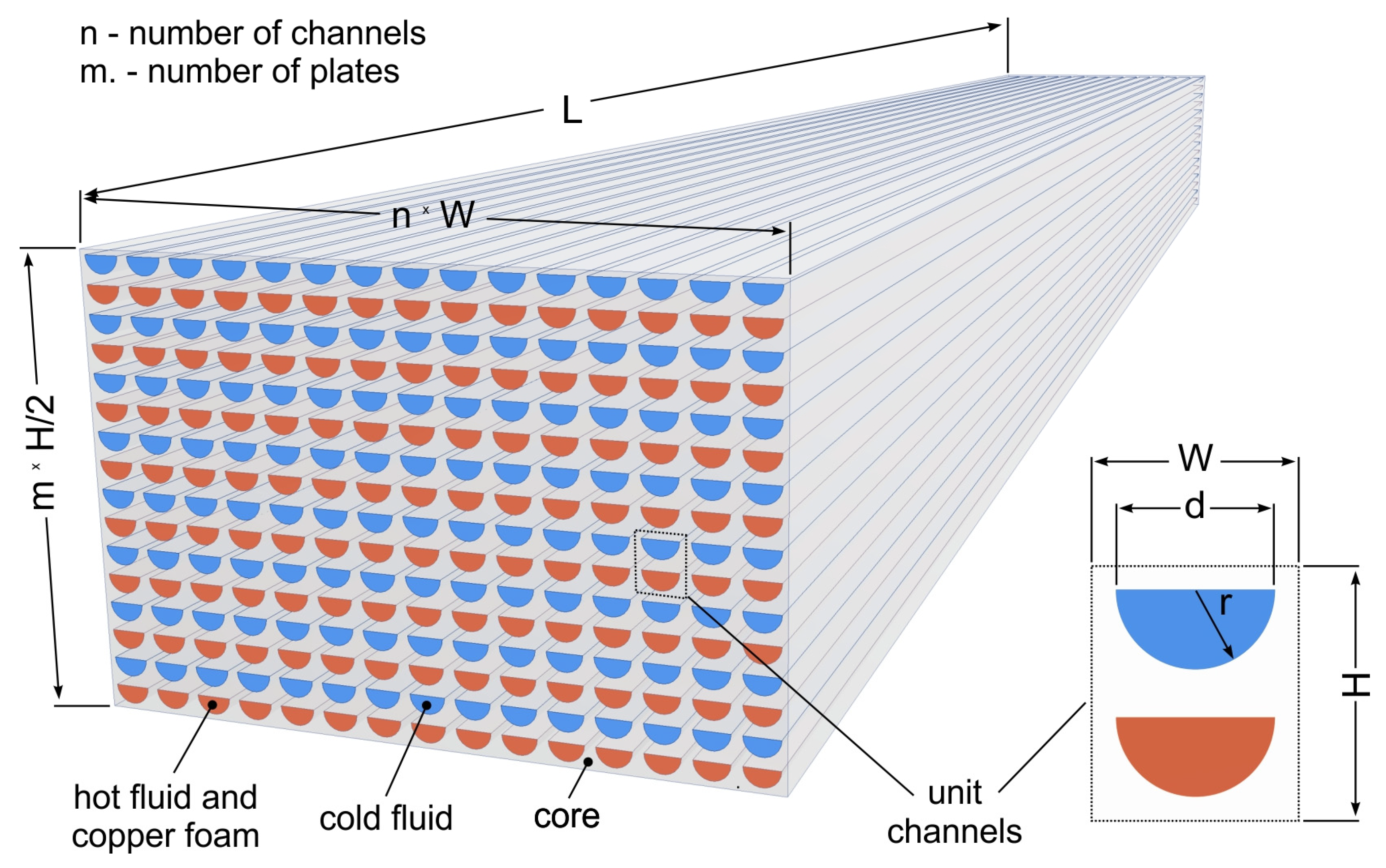
Taking into account the aim of the presented research, namely determining the influence of flow channel filling with metal foam on the effectiveness of printed circuit heat exchangers, numerical studies were conducted based on a heat exchanger model covering only its central part (Figure 4), in which channels of both fluids are parallel and straight to each other. Conducting simulations using straight channels allowed excluding the influence of fluid stream turbulence on local heat transfer and pressure losses at points of flow direction change. This was necessary for unambiguous interpretation of the foam’s significance.
Numerical studies were conducted for channels with a semicircular cross-section and 200 mm length. The transverse dimensions of the channel were 2, 3, and 4 mm.
Channels with an approximately 2 mm diameter are typical for printed circuit heat exchangers. Some heat exchangers of this type have channels with smaller diameters, which allow obtaining a larger heat transfer surface area; however, in the case of the need to place metal foam in the channel, there is a risk of losing patency of channels with too small cross-sections. The foam should be connected to the wall by soldering to ensure good thermal contact. Larger channels were adopted to evaluate the influence of channel diameter on the overall thermal–hydraulic performance of printed circuit heat exchangers with metal foam. A diameter of 4 mm is the maximum channel size that can be achieved using photochemical etching. The dimensions characterizing the flow channels of the heat exchanger are presented in Table 2.
It was assumed that the parameters of foam filling the heat exchanger channels would be consistent with the parameters of copper foam used in experimental studies described in work [37]. The parameters of this foam are presented in Table 3. The choice of metal foam was determined by the high thermal conductivity of the copper skeleton and high porosity. In the case of using metal foams in thermal apparatus, foams with pore density in the range of 40–60 PPI are usually used. Foams with lower pore density have smaller unit surface area. At high pore densities, hydraulic resistance increases disproportionately. Foam permeability and inertial coefficient were determined according to the methodology described in work [38], based on measurements of air pressure drop in a straight channel with a length of 200 mm. Due to planned experimental studies with a prototype heat exchanger made of brass, brass-c22000 was adopted as the PCHE core material.
Brass is a material with relatively high thermal conductivity and mechanical strength, which is advantageous in the operation of high-pressure heat exchangers. This material can be easily joined to copper using soldering. In the prototype heat exchanger, which will be built for experimental testing, copper foam will be soldered to the inner surface of the gas channels. Soldering will ensure very good thermal contact between the foam skeleton and the heat exchanger core. The prototype heat exchanger will have a construction typical of printed circuit heat exchangers, i.e., its main part will be a rectangular core composed of a stack of flat plates. The copper foam intended for integration into the gas channels will be prepared in the form of inserts with a shape and dimensions matching the cross-section of the channel. The inserts will be cut from a sheet of metal foam of appropriate thickness using electro-spark cutting and placed in the channels before the plates are stacked. Prior to this, the surface of the plates, including the surface of the channels, will be coated with tin solders. After all parts of the heat exchanger core have been assembled, it will be bolted together and heated in a heating chamber to a temperature higher than the melting point of the tin solders. The effectiveness of this assembly technique has been tested in experimental studies of another type of heat exchanger with copper foam [37].

2.2. Computational Domain and Boundary Conditions

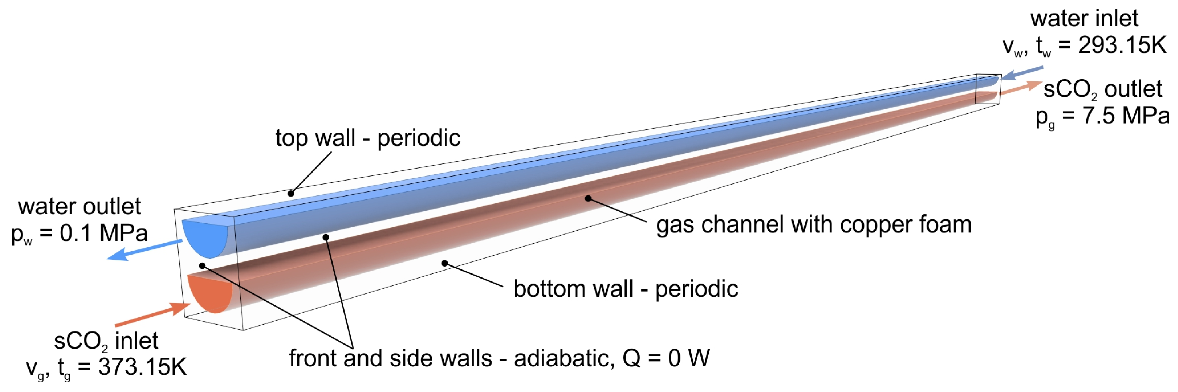
Similarly to other works concerning numerical studies of printed circuit heat exchangers, the computational domain was limited to two adjacent cold and hot fluid channels (Figure 5). Due to the periodic distribution of channels in the heat exchanger core, such an approach is possible, as demonstrated by the authors of works [5,9,11,12,16,18,19,29,39,40].
The research was conducted assuming constant fluid velocities and temperatures at the inlet to the channels, in countercurrent flow. The lower and upper surfaces of the computational domain were assigned a periodicity condition due to the repeatability of the domain in the heat exchanger core. In the heat exchanger core, fluid channels with the same temperature are adjacent to each other in the horizontal planes, so it can be assumed that there is no heat transfer in the horizontal direction. For this reason, the condition of adiabatic walls was assumed for the side surfaces of the computational domain. This approach is commonly used in numerical simulations of PCHE heat exchangers [12,16,17,22,25]. The gas channel (lower) is filled with metal foam along its entire length and was therefore treated as a porous zone. For this space, parameters describing the pressure drop were determined based on the permeability and inertial coefficient of the foam.
Table 4 presents the constant boundary conditions assigned to the computational domain according to the designations in Figure 5.

2.3. Numerical Schemes and Validation

Numerical studies were conducted using Ansys Fluent version 2024R2. Fluid flow in empty channel (without foam) was simulated using the Shear Stress Transport k-ω turbulence model (SST k-ω). The Shear Stress Transport k-ω model effectively combines the advantages of two other common turbulence models: the k-ω model and the k-ε model. It utilizes the robust and accurate formulation of the k-ω model in the near-wall region, which is crucial for capturing intense flow phenomena and accurately modeling boundary layer behavior. It leverages the independence and robustness of the k-ε model in the bulk flow region far from the wall, ensuring accurate simulation in the mainstream flow. Shear Stress Transport k-ω is particularly suitable for predicting heat and mass transfer processes involving strongly variable physical properties of fluids near walls. This is critical for supercritical fluids like sCO2, which exhibit dramatic property changes, especially near the pseudo-critical point. The Shear Stress Transport k-ω model was employed and successfully verified in heat transfer studies in PCHE by the authors of the papers [1,5,7,11,12,19,25,26,29,40,41].
According to the SST k-ω model, the equations governing flow take the following form:
continuity equation,
ρ t + ρ u i = 0 ,   i   =   x ,   y ,   z ,
the momentum equation,
u i t + u j u i x j = 1 ρ p x i 1 ρ x j μ + μ t u i x j + u j x i ,
turbulent kinetic energy transport equations k and turbulent specific dissipation rate ω,
t ρ k + x i ρ k u i = x j Γ k k x j + G k Y k + S k ,
t ρ ϖ + x j ρ ϖ u j = x j Γ ϖ θ x j + G ϖ Y ϖ + D ϖ + S ϖ ,
where Gk represents the generation of turbulence kinetic energy and Gω is the production of specific dissipation rate. A detailed description of other quantities can be found in [42].
The region of the channel filled with metallic foam was classified as a porous domain characterized by uniform and isotropic properties. For modeling fluid transport within this space, the extended Darcy framework by Forchheimer–Brinkman was employed, which incorporates both viscous effects and inertial contributions. Based on this mathematical framework, the momentum equation for the foam domain takes the following form:
ρ f ε 2 V T V = P f + μ f , e f f 2 V μ f K + ρ f C f K V V .
In this equation, the quantities permeability K and inertial coefficient CF are specific to a given metal foam. Their value was determined based on pressure drop investigations.
According to the local thermal non-equilibrium (LNTE) model, heat transfer in the flow through metal foam was treated as a process in which the temperature of the fluid and the solid differ. The LTNE model accounts for the distinct temperature difference between the solid matrix and the flowing fluid by employing two coupled energy equations—one for the solid phase and another for the fluid phase. This approach is essential for obtaining accurate results. The energy equation for a fluid takes the form
ρ c p f V T = ε k f T + h s f a s f T s T f ,
and for a solid
0 = 1 ε k s T s h s f a s f T s T f .
Various studies, including references [43,44,45,46,47,48], have established that when dealing with fluid flow within metal foams, the local thermal non-equilibrium model yields significantly more accurate heat transfer characterization compared to the thermal equilibrium (LTE) model commonly employed in other porous media. Research findings [49,50] reveal that in copper foam applications, heat transfer coefficients derived from LTE calculations may overestimate values by over 20% relative to LTNE model predictions. The LTNE effect becomes particularly pronounced for metal foams made from highly conductive materials such as copper or aluminum, which possess solid thermal conductivity typically three to five orders of magnitude higher than common fluids like air or water. This vast disparity ensures significant temperature differences between phases. Higer porosity leads to more pronounced LTNE effects and greater solid–fluid temperature differences. Small duct dimensions and low pore density also increase solid–fluid temperature inhomogeneity. The LTNE effect is particularly noticeable at low Reynolds numbers and in inlet regions of the flow.
Interfacial convection heat transfer coefficient hsf (in Equations (6) and (7)) is described according to correlations (8) proposed by Zukauskas [51] and considered in [42].
h s f = 0.76 Re d l 0.4 Pr 0.37 k f d ; 1 Re d l 40 0.52 Re d l 0.5 Pr 0.37 k f d ; 40 < Re d l 10 3 0.26 Re d l 0.6 Pr 0.37 k f d ; 10 3 < Re d l 2 10 5 .
Interfacial surface area asf is described by equation
a s f = 3 π d l 0.59 d p 2 1 e ( 1 ε ) / 0.04 ,
where dl (skeleton ligament diameter) is described by Equation (10) developed by [52],
d l d p = 1.18 1 e ( 1 ε ) / 0.04 ,
in conjunction with the pore diameter dp,
d p = 0.0254 ω .
The thermophysical properties of fluids are determined for local temperature and pressure. Water was treated as an incompressible fluid. Supercritical carbon dioxide was treated as a real gas. Its properties were obtained from the National Institute of Standards and Technology (NIST) database.
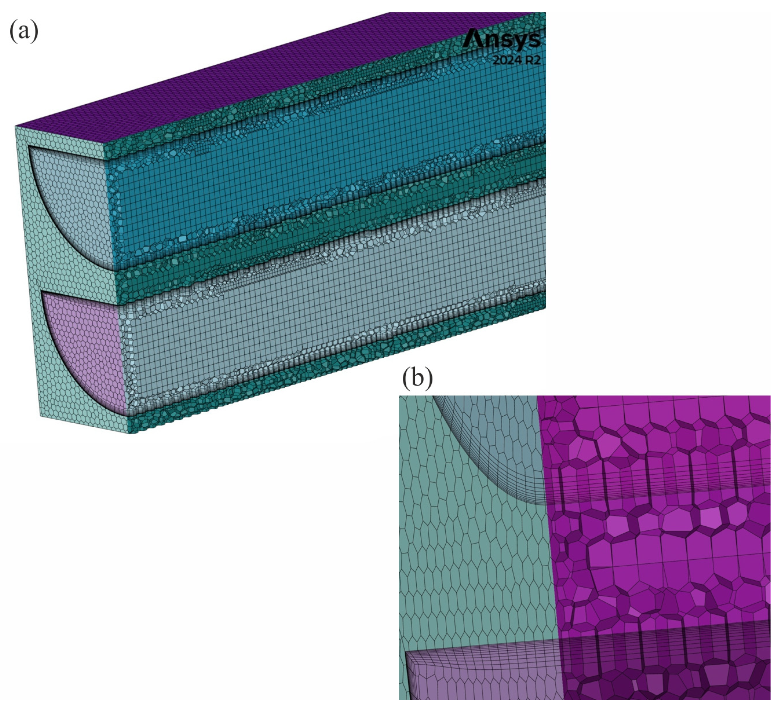
The SST k-ω model requires appropriately dense discretization of the computational domain, especially near the channel wall, so that the Y+ parameter is approximately 1. The computational domain was discretized using polyhedral and hexahedral elements (Figure 6). An inflation layer was applied in the fluid space at the channel surface.
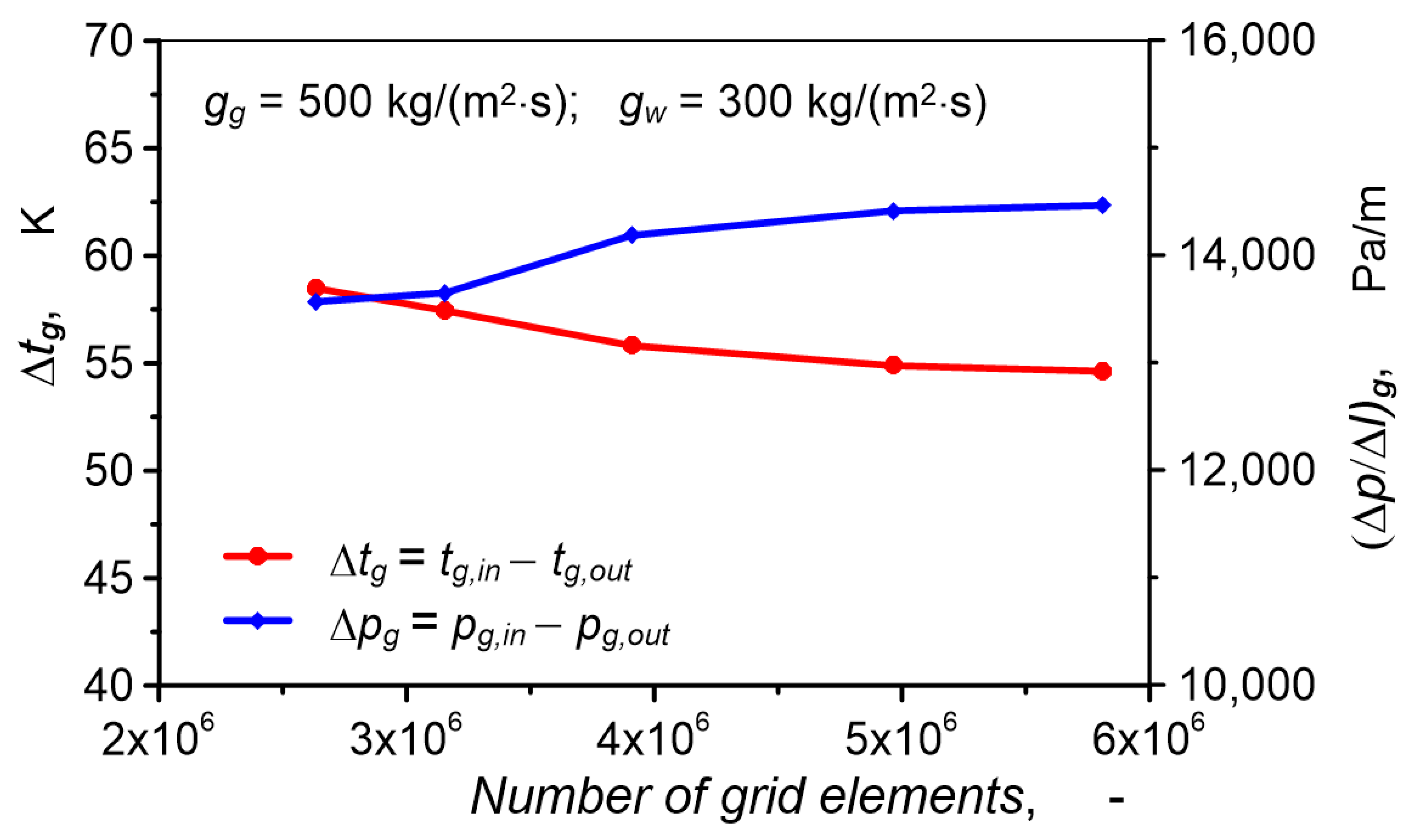
The grid density was established by analyzing the results of a selected calculation case conducted in a domain with an increasing number of cells. When the values of selected parameters characterizing the simulated phenomena stabilize at a constant level, the grid density is considered sufficient. This procedure has been used by the authors of many numerical studies of PCHE heat exchangers [1,2,5,11,16,25,29,40,41]. The evaluated parameters were the temperature change Δtg and pressure Δpg of carbon dioxide. As shown in Figure 7, with an increasing number of grid elements, changes in these parameters become smaller. Differences between grids with 5.0 and 5.8 million elements are only 0.4% for pressure drop and 0.5% for temperature drop. Therefore, in all analyzed flow cases, grids with more than 5 million elements were used.

2.4. Simulation Conditions

The operating parameters for which the tests described in this paper were carried out, including pressure, temperature, and mass flux of water and carbon dioxide, are consistent with typical values for industrial processes and fall within the range of changes in these parameters in studies by other authors (Table 1).
The maximum cooling water flux was selected so that carbon dioxide after cooling remained in a supercritical state, meaning its temperature was not less than 304.13 K. Numerical studies for all three channels were conducted under the same operating conditions presented in Table 5. For the 2 mm diameter channel, additional studies of carbon dioxide cooling during flow through a channel without metal foam were conducted. This case was treated as a reference for evaluating the influence of metal foam on heat exchanger operation.

3. Results and Discussion

3.1. Data Reduction

The analysis of the simulation results was carried out based on parameters characterizing heat and flow phenomena typical for heat exchangers.
The hydraulic diameter of semicircular channels was taken as the value obtained from the ratio of four times their cross-section and channel cross-section circumference
d h = π d 0.5 π + 1 .
This dimension was used to determine flow turbulence,
Re = g d h μ .
The Fanning factor f was determined based on pressure drop according to the equation
f = ρ Δ p d h 2 g 2 L .
The heat flux per unit volume of the heat exchanger qgV can be calculated according to equation
q g V = q g a H E x
where aHEx is the heat exchanger specific surface area and qg is the heat flux.
The value of the heat transfer coefficient on the gas side, determined according to equation,
h g = q g t g t s .
Thermal effectiveness ε was calculated based on the enthalpy of sCO2, due to the high variability of the properties of supercritical carbon dioxide,
ε = Q min Q 1 , Q 2 100 % ,
where
Q 1 = m g H g , 100 H g , 20
Q 2 = m w H w , 100 H w , 20 .
Q1 and Q2 denote actual heat transfer rate, and Hg,100 and Hg,20 are the enthalpy of carbon dioxide at initial temperature 100 °C and the lowest achievable temperature 20 °C, equal to the initial water temperature. Similarly, Hw,20 and Hw,100 denote water enthalpy at two extreme temperatures.
Overall thermal–hydraulic performance of heat exchangers was compared using the performance evaluation criterion PEC,
P E C = j m f j o f m f f o 2 / 3 ,
In which Colburn factor j determines thermal performance of the heat exchanger and Fanning friction factor allows consideration of the influence of pressure drop and associated energy costs for pumping fluid through the heat exchanger on overall thermal–hydraulic performance. Values with index “o” refer to the reference heat exchanger. In the analyzed case, this is a heat exchanger without metal foam with a 2 mm diameter channel.
Colburn factor was determined according to the equation
j m f = h g c Pr 2 / 3 ,
and
j o = N u Re Pr 1 / 3
where Prandtl number,
Pr = μ c k

3.2. Flow and Thermal Visualization

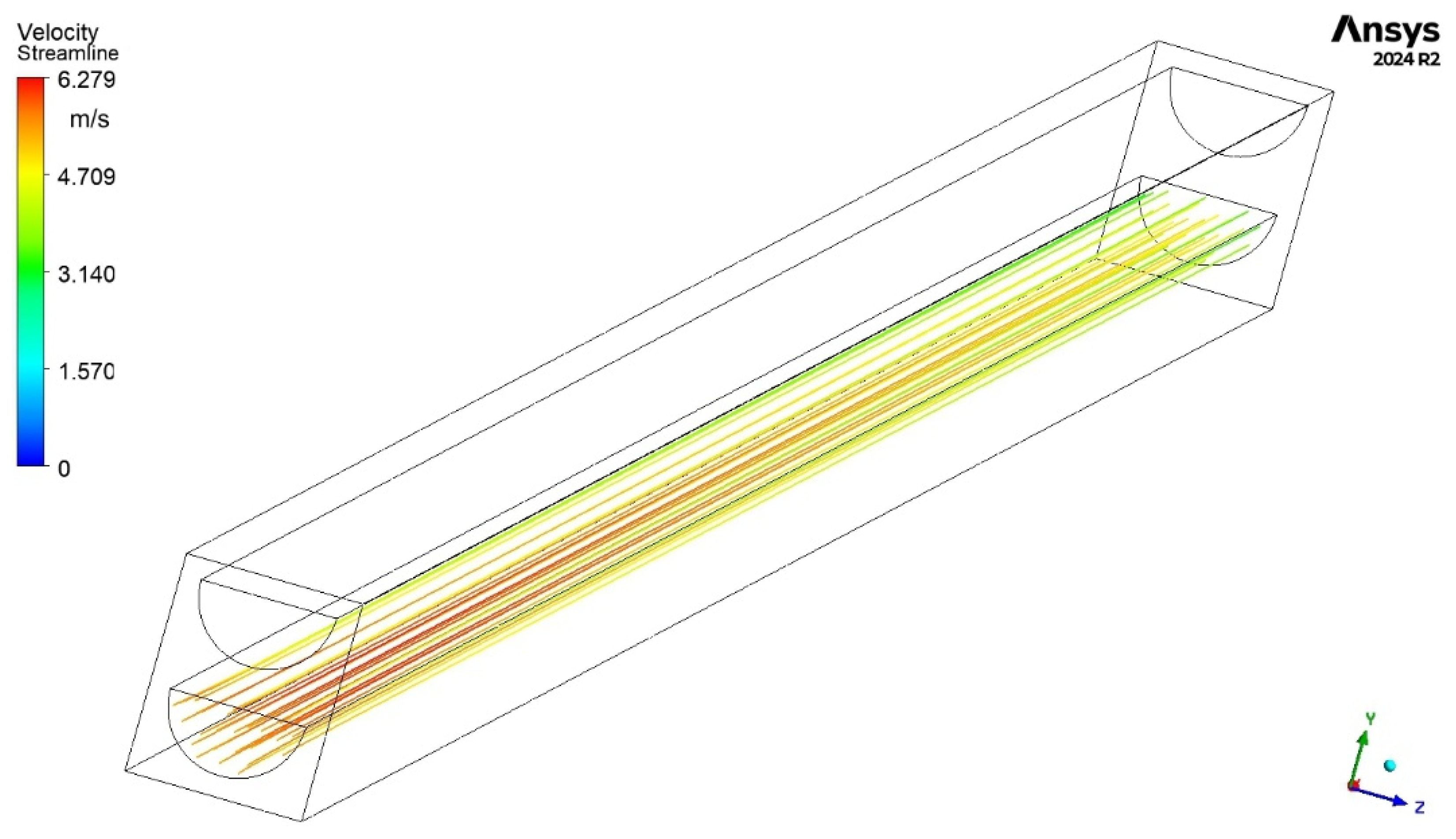
The regular and straight shape of the flow channels with a constant cross-section prevents fluid turbulence in the flow. Gas streamlines are straight and parallel along their entire length for all cases studied, both in flow through channels filled with copper foam and in an empty channel. As an example, Figure 8 shows gas streamlines in an empty channel with a diameter of 2 mm.
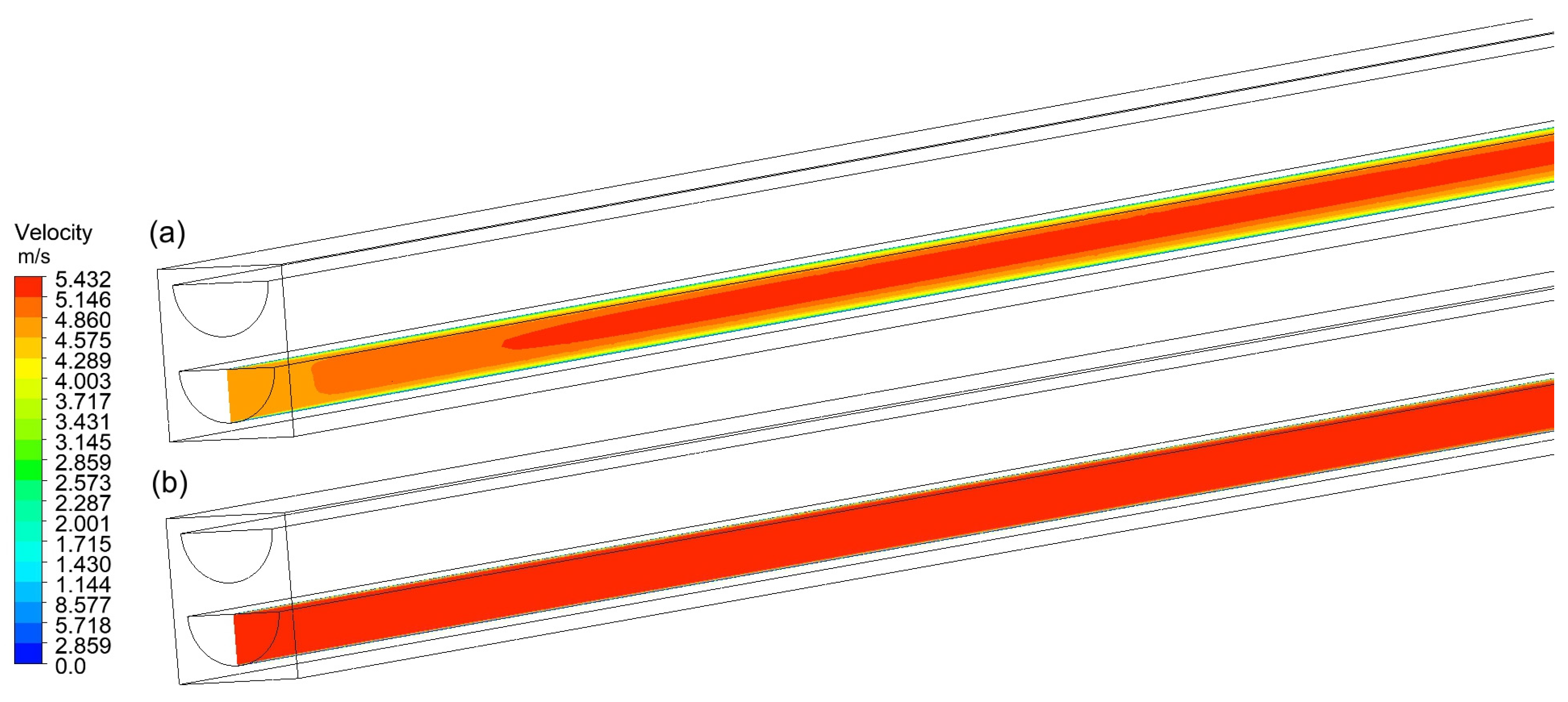
Despite the same straight flow in the channel without metal foam and in channels with foam, there is a clear difference in the field of gas velocity in the empty channel and in the filled channels, as shown in Figure 9. In the empty channel near the inlet, a typical flow stabilization zone can be seen, in which the sCO2 velocity gradually changes as it moves away from the inlet. In channels with copper foam, the flow stabilizes very quickly. As can be seen in Figure 9b, the gas velocity in the inlet zone is almost constant, which is typical for flow through porous media. (Due to the large ratio of the computational domain length to the transverse dimensions, Figure 9, as well as some other figures below, shows only the initial length of the channels. Including the entire channel does not allow for a sufficiently clear presentation of the required details).
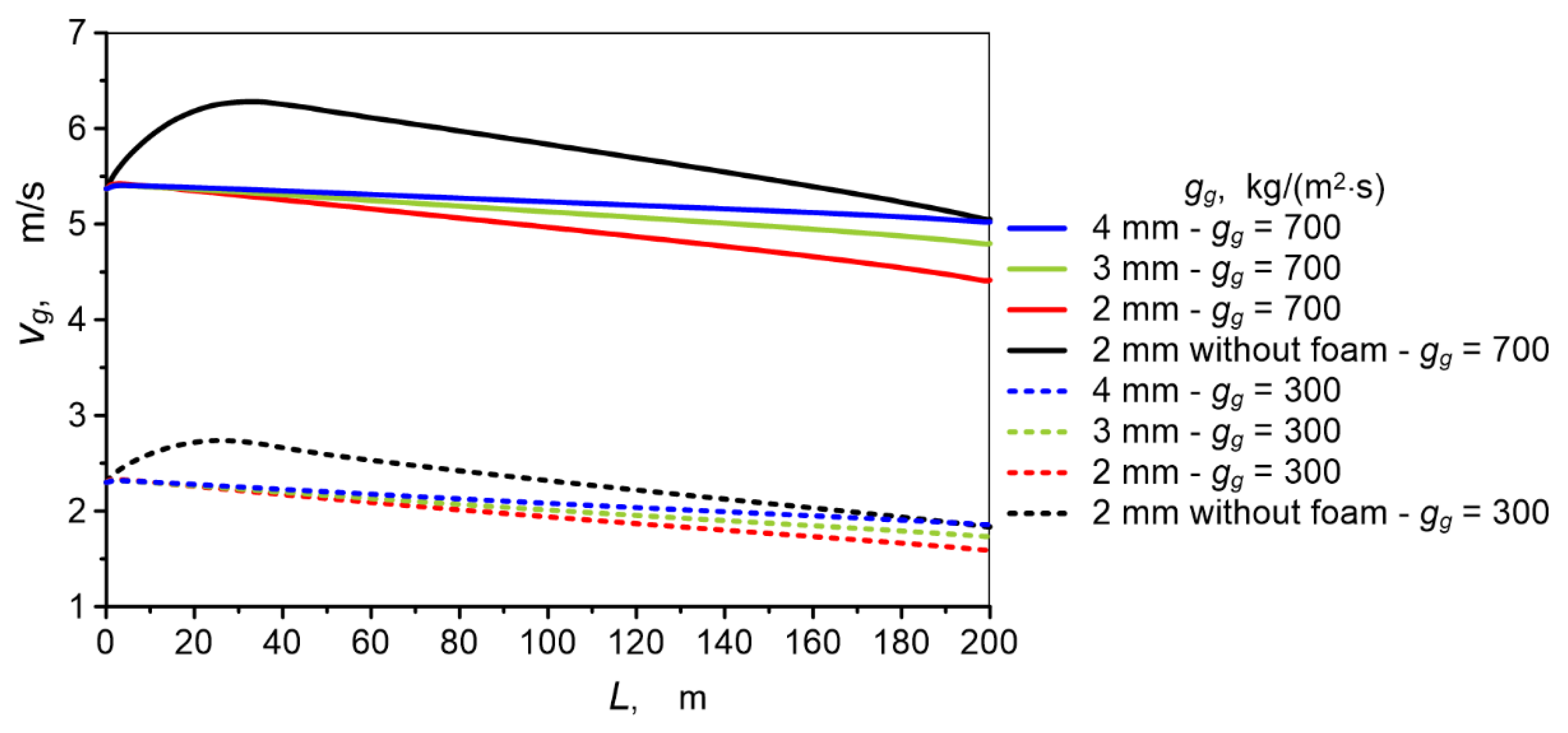
The differences in velocity field in the inlet zone are confirmed by the change in local gas velocity read on the channel axis (a straight line lying on the vertical plane of symmetry of the channel at half its height) as the distance from the channel inlet increases. As can be seen in Figure 10, in the case of a channel without copper foam, the axial gas velocity initially increases in the flow stabilization zone until it reaches its maximum value. After the flow stabilizes, the gas velocity decreases with distance from the inlet, which is caused by an increase in the density of sCO2 as the gas cools. In an empty channel, the flow stabilizes over a length of approximately 40 mm at the highest gas flow rate. In channels with metal foam, the maximum axial velocity occurs at a distance comparable to the channel diameter.
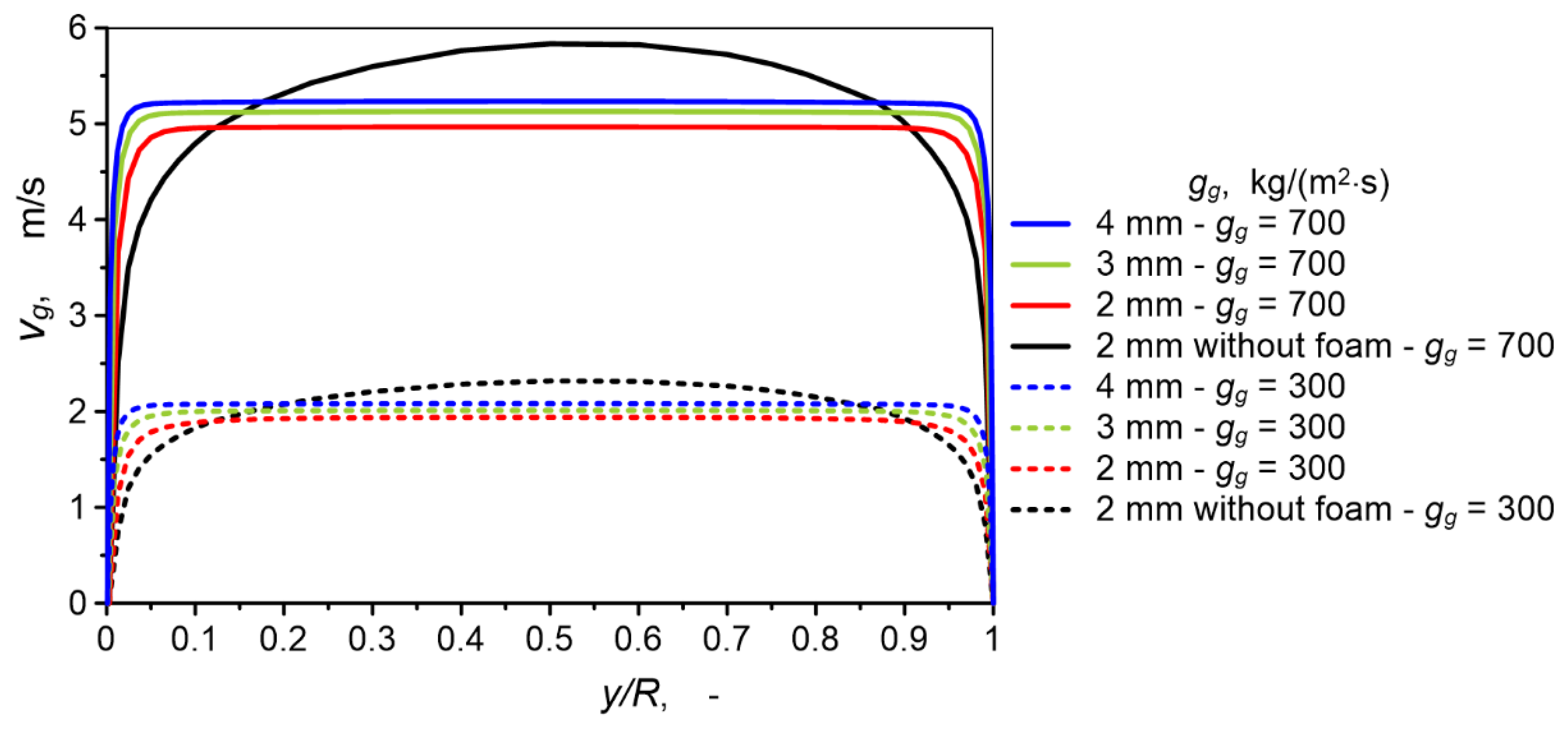
Once the flow has stabilized, the gas velocity profile in the cross-section of the empty channel has the shape of a flattened parabola, typical of turbulent flow. In channels with copper foam, the velocity profile is almost flat. In the central zone of the cross-section, the velocity is constant and decreases rapidly to zero near the channel wall. Figure 11 shows a comparison of velocity profiles for sCO2. The data in this figure were read for the vertical axis of the channel lying at the intersection of the channel’s plane of symmetry and the cross-section of the channel, located in the middle of the channel length. Figure 12 shows a comparison of the velocity field in the same cross-section.
Changes in velocity are reflected in the turbulence of the flow. The value of turbulence kinetic energy in the inlet zone of the empty channel is more variable than in the channel with metal foam under the same flow conditions (Figure 13).
The value of turbulence kinetic energy in the cross-section of channels with copper foam is constant across almost the entire cross-section and, like velocity, varies only in a very narrow area near the channel wall (Figure 14).
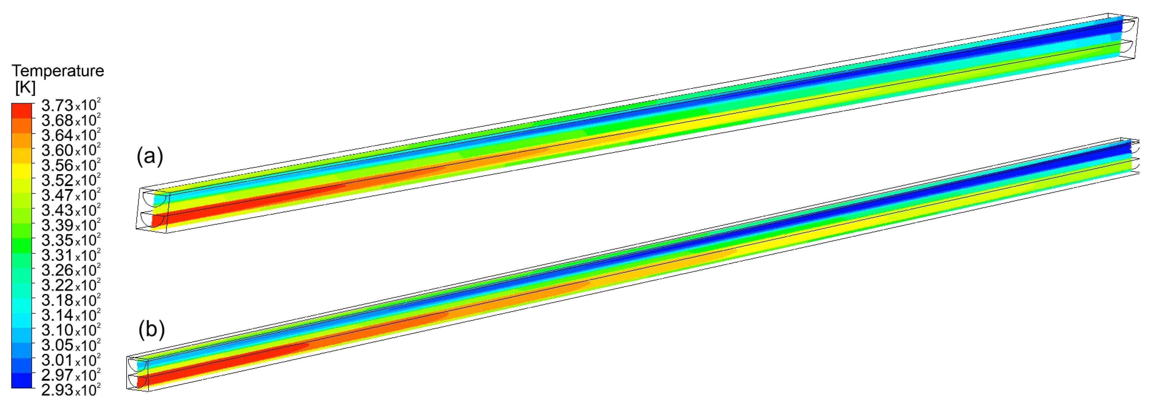
The temperature of the fluids and the heat exchanger core material changes gradually along the length of the channels in accordance with the countercurrent flow direction, as illustrated in Figure 15.
The temperature of the heat exchanger core is almost constant locally (in a specific cross-section). The high thermal conductivity of brass causes the temperature to equalize. The temperatures of points located near the hot sCO2 channel and the cold water channel differ only slightly (Figure 16). The gas temperature in channels filled with foam is more uniform than in the gas channel without metal foam and in empty water channels. This is due to heat transport through the copper skeleton of the foam, which occupies the entire cross-section of the filled channels. In a 2 mm diameter channel with metal foam, the sCO2 temperature is constant across the entire cross-section of the channel. In larger channels, gas temperature variability can be observed because the beneficial effect of foam on heat exchange weakens with increasing distance from the wall. The thin ligaments of the foam skeleton have a limited heat transport capacity.

3.3. Heat Transfer

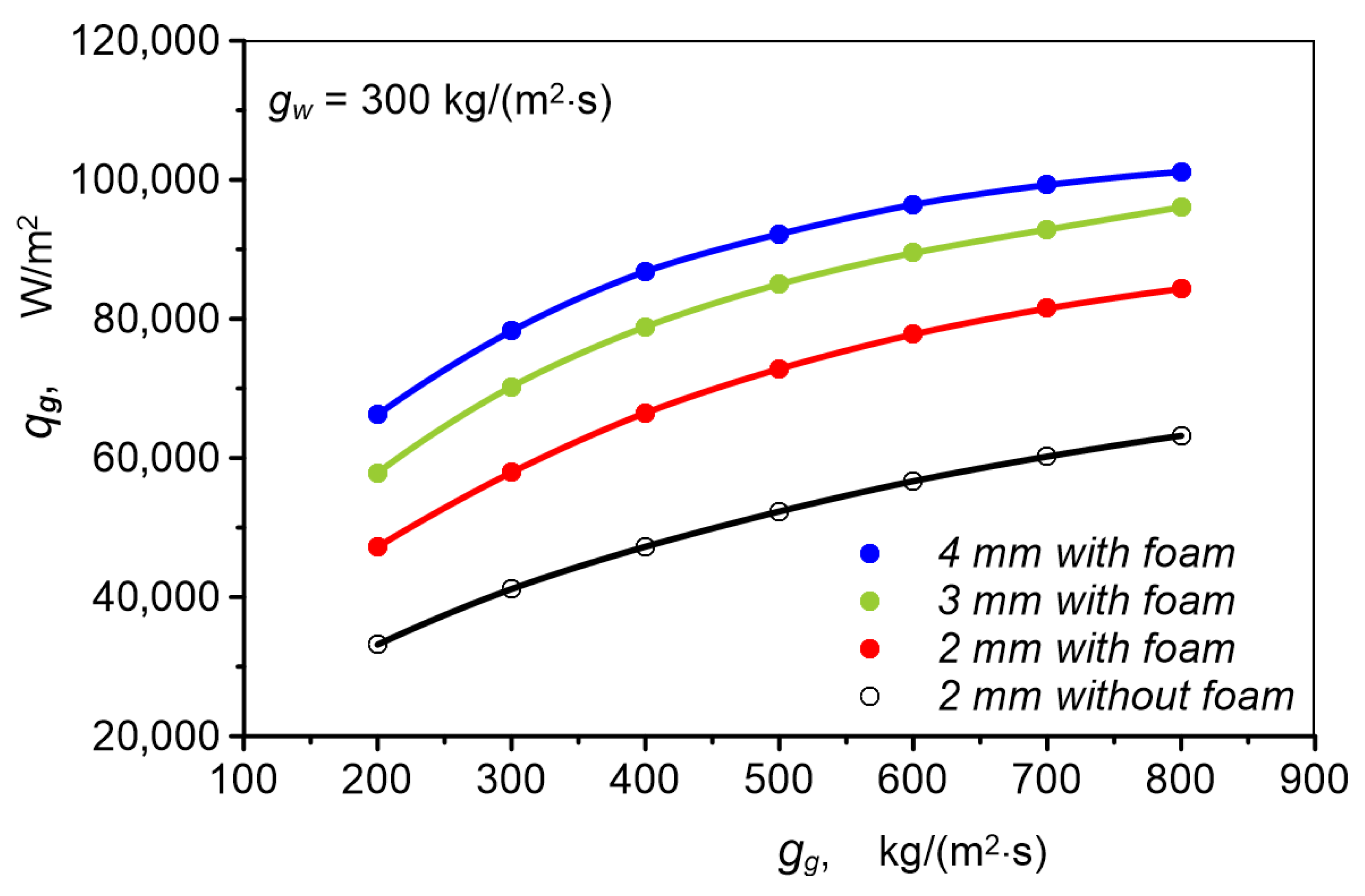
Figure 17 presents the heat flux qg released by carbon dioxide to the channel wall (value reported by Fluent) during gas cooling in an empty channel (without foam) and in channels with metal foam. In all channels with foam, heat flux is higher than in the case of an empty channel. In a 2 mm diameter channel filled with metal foam, the gas releases 33% to 63% more heat than in an empty channel of the same diameter. Heat flux increases with channel diameter. During flow through a 4 mm diameter channel, heat flux is 20% to 40% higher than in a foam-filled channel with 2 mm diameter. At the same gas mass flux in all channels, the largest gas mass flow rate flows through the 4 mm diameter channel. With increasing channel diameter, mass flow rate increases faster than heat transfer surface area, which causes heat flux to reach the highest values when flowing through channels with the largest diameter.
The influence of channel diameter is analogous when carbon dioxide cooling occurs at constant gas mass flux and variable water mass flux (Figure 18). The gas releases the most heat when flowing through a foam-filled channel with 4 mm diameter, and the least in an empty channel with 2 mm diameter.
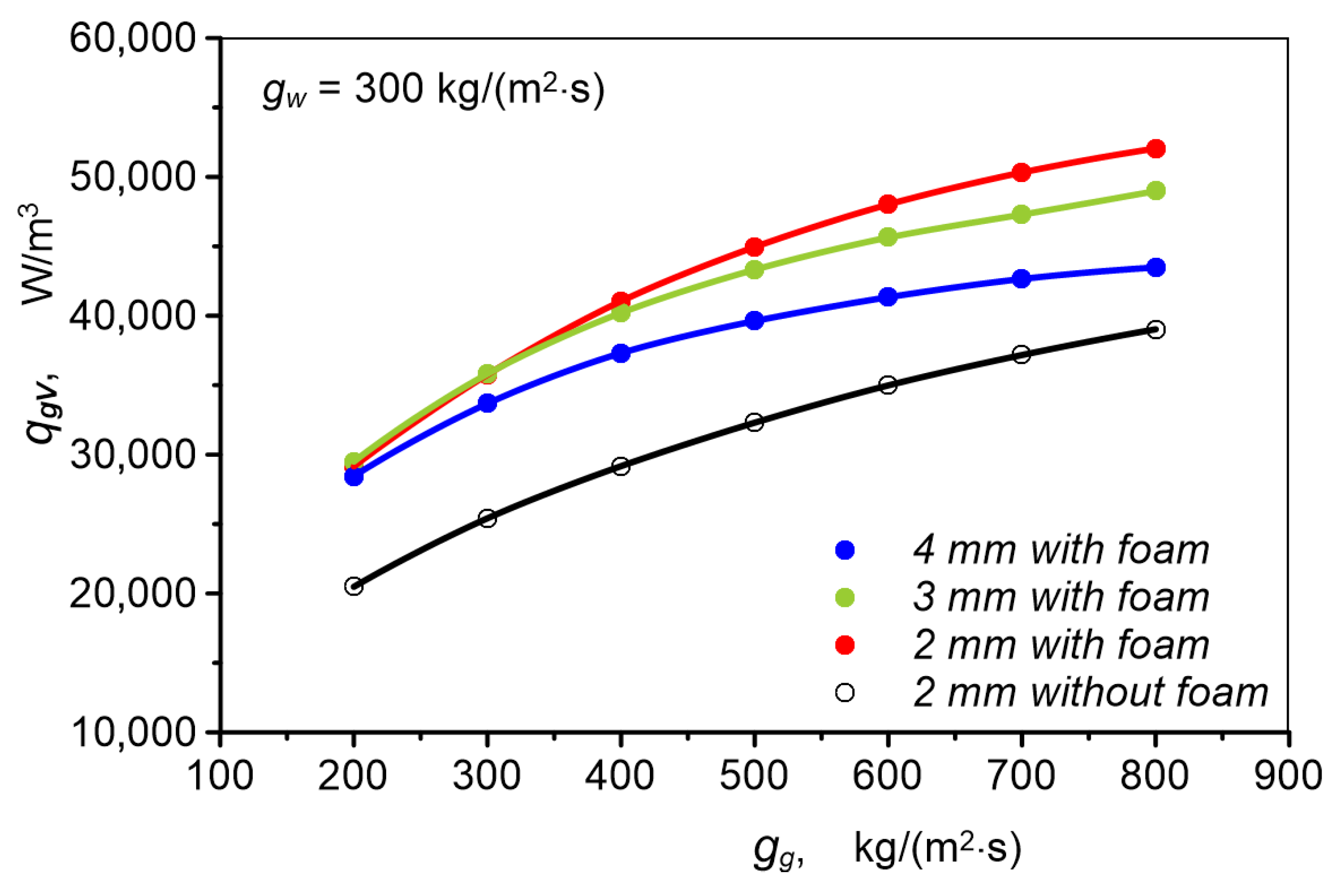
The heat exchanger core with 2 mm diameter channels is characterized by the largest unit heat transfer surface area aHEx (total heat transfer surface area per 1 m3Table 2), which causes the largest heat flux qgV (Equation (15)) to be achieved in a heat exchanger with a 2 mm diameter channel filled with metal foam, relative to the size of the heat exchanger core, despite the fact that the largest heat flux qg is transported in a unit channel with a 4 mm diameter. In the case of other channels filled with metal foam, the value of qgV is also higher than in an empty channel, as illustrated in Figure 19.
Heat flux increases with increasing fluid fluxes. With increasing carbon dioxide flux, its velocity and turbulence increase, causing more intensive heat transfer between the gas and channel wall. Higher water flow velocity intensifies heat transfer in the water channel, which is also reflected on the gas side. Due to greater intensity of heat transport to water, the gas can release a larger amount of heat. The value of the heat transfer coefficient on the gas side is presented in Figure 20. It is clearly visible that in channels filled with metal foam, the heat transfer coefficient has a higher value than in an empty channel. Changes in the heat transfer coefficient are, however, more complex than changes in heat flux. The difference between the heat transfer coefficient in an empty channel and in filled channels increases with increasing carbon dioxide flux. This is most visible in the case of a 2 mm diameter channel filled with foam. When the gas mass flux is small and does not exceed 500 kg/(m2·s), the heat transfer coefficient has a value lower than in channels with 3 and 4 mm diameter. With further increase in carbon dioxide mass flux, the heat transfer coefficient rapidly increases in an exponential manner. In a 4 mm diameter channel, the change in heat transfer coefficient value with increasing gas mass flux is least intensive and proceeds in a manner similar to linear. In a 3 mm diameter channel, a smaller dependence of the heat transfer coefficient on gas mass flux is observed than in a 2 mm channel, but greater than in the case of a 4 mm diameter channel.
A certain regularity can be observed in the dependence of the heat transfer coefficient on channel size. The highest value of the heat transfer coefficient in the channel with the smallest diameter at high carbon dioxide mass fluxes can be explained by specific heat transfer conditions in channels filled with metal foams. As shown in work [53], metal foam participates in heat transfer only in a relatively small fluid region located near the channel wall. This region encompasses a distance from the wall equivalent to the size of one cell. In a 2 mm diameter channel, the foam interaction area therefore encompasses a larger part of the channel cross-section than in channels with 3 and 4 mm diameter.

3.4. Pressure Drop

Comprehensive evaluation of a heat exchanger requires consideration of pressure drop, which reduces thermal–hydraulic performance. In the studied case, this is particularly significant because fluid flow through metal foams is associated with relatively high pressure drop. As shown in Figure 21, pressure drop of carbon dioxide flow through channels filled with metal foam is 45 to 82 times higher than pressure drop through an empty channel. The value of pressure drop through channels with metal foam depends very little on channel diameter, which is typical for flow through channels with porous filling. The share of pressure drop related to friction against the channel wall in total pressure drop is very small, due to the many times greater resistance of flow through the porous medium.
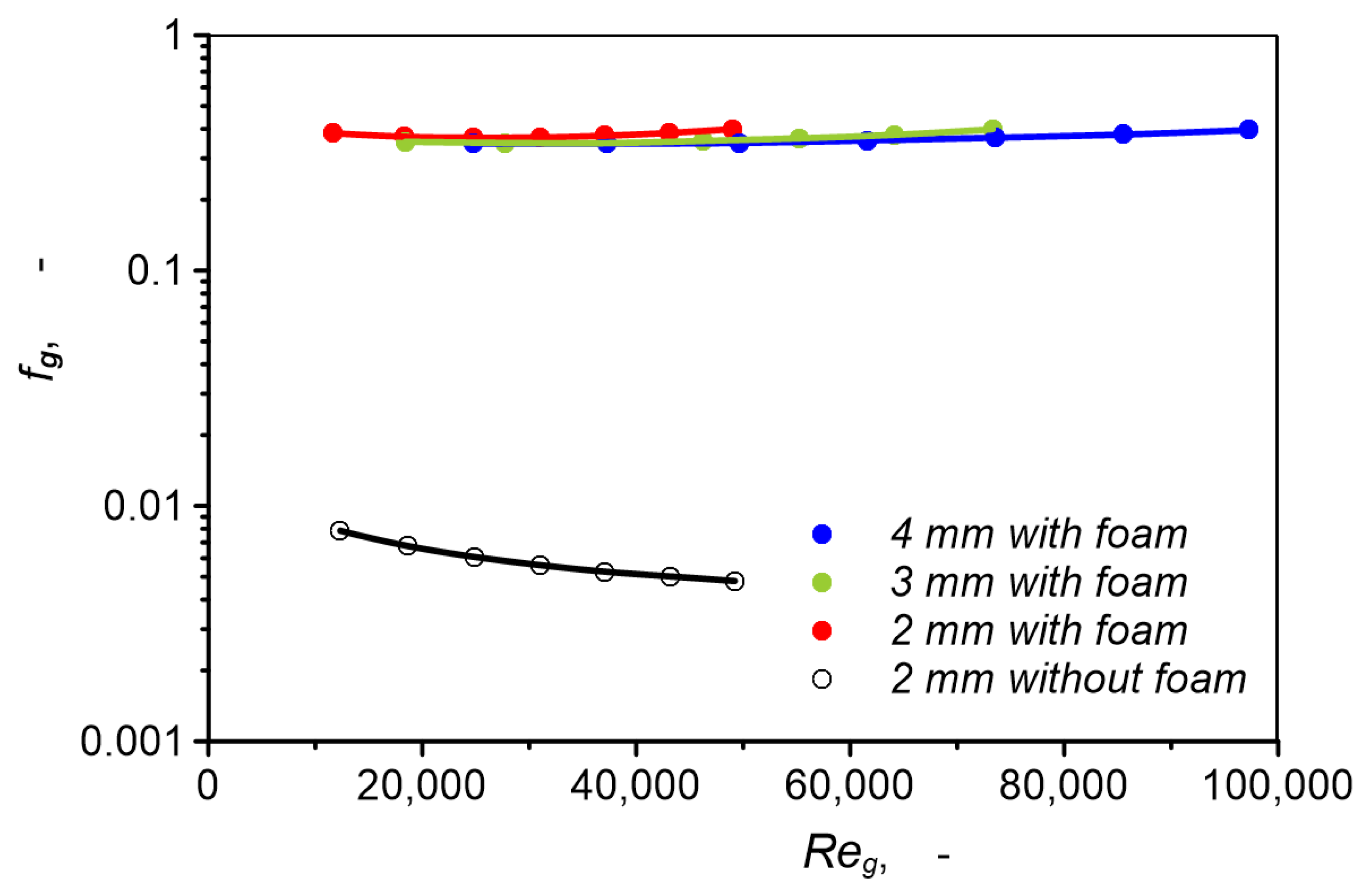
The almost identical value of the Fanning factor for all three channels and its slight dependence on the Reynolds number, presented in Figure 22, confirms that pressure drop depends mainly on structural parameters of the foam, which is identical in all channels.
Reynolds numbers in the range 11,636–97,257 and almost constant value of the Fanning factor indicate that carbon dioxide flow in foam-filled channels was turbulent throughout the entire research range, which is favorable for heat transport.

3.5. Heat Exchanger Efficiency

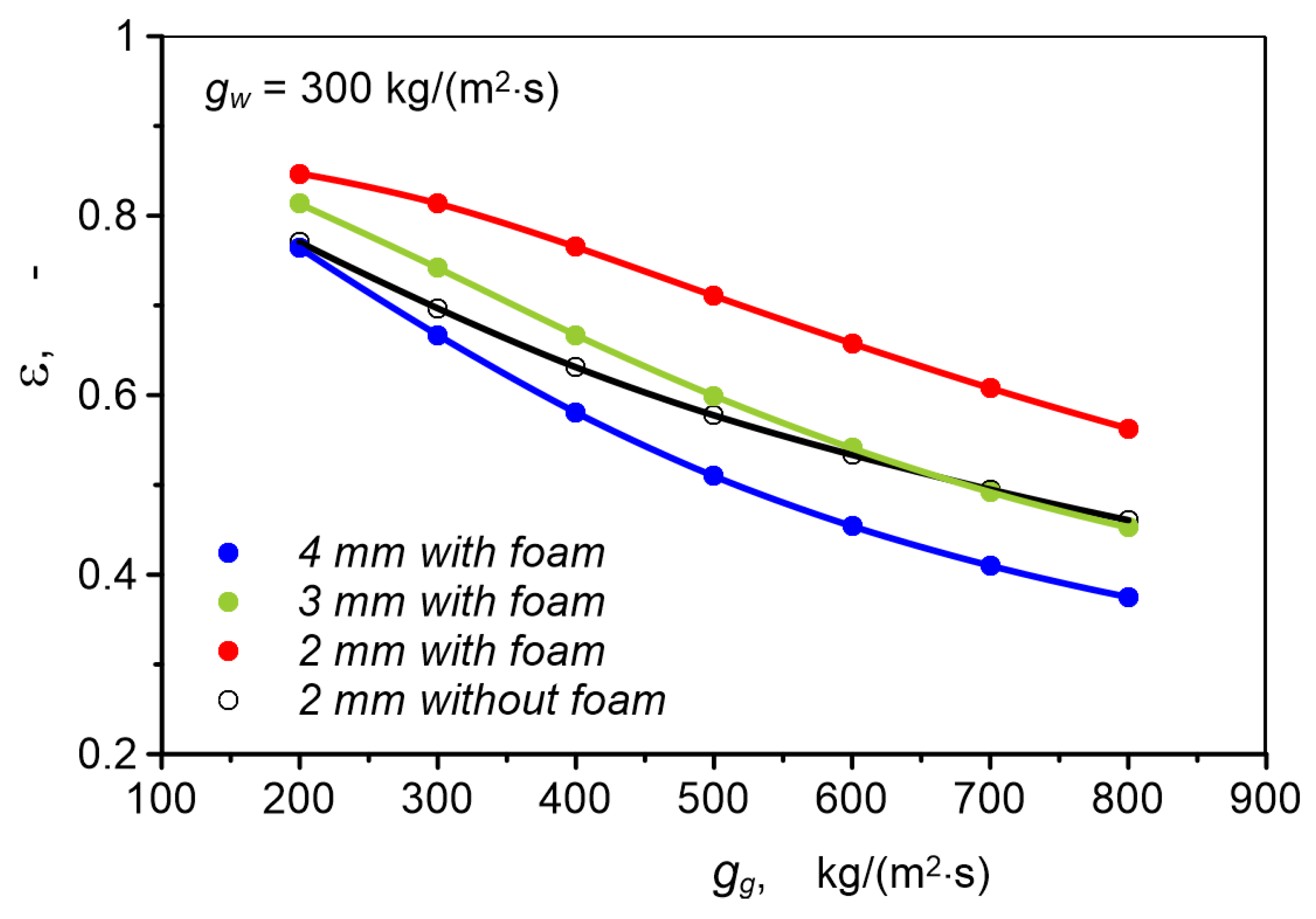
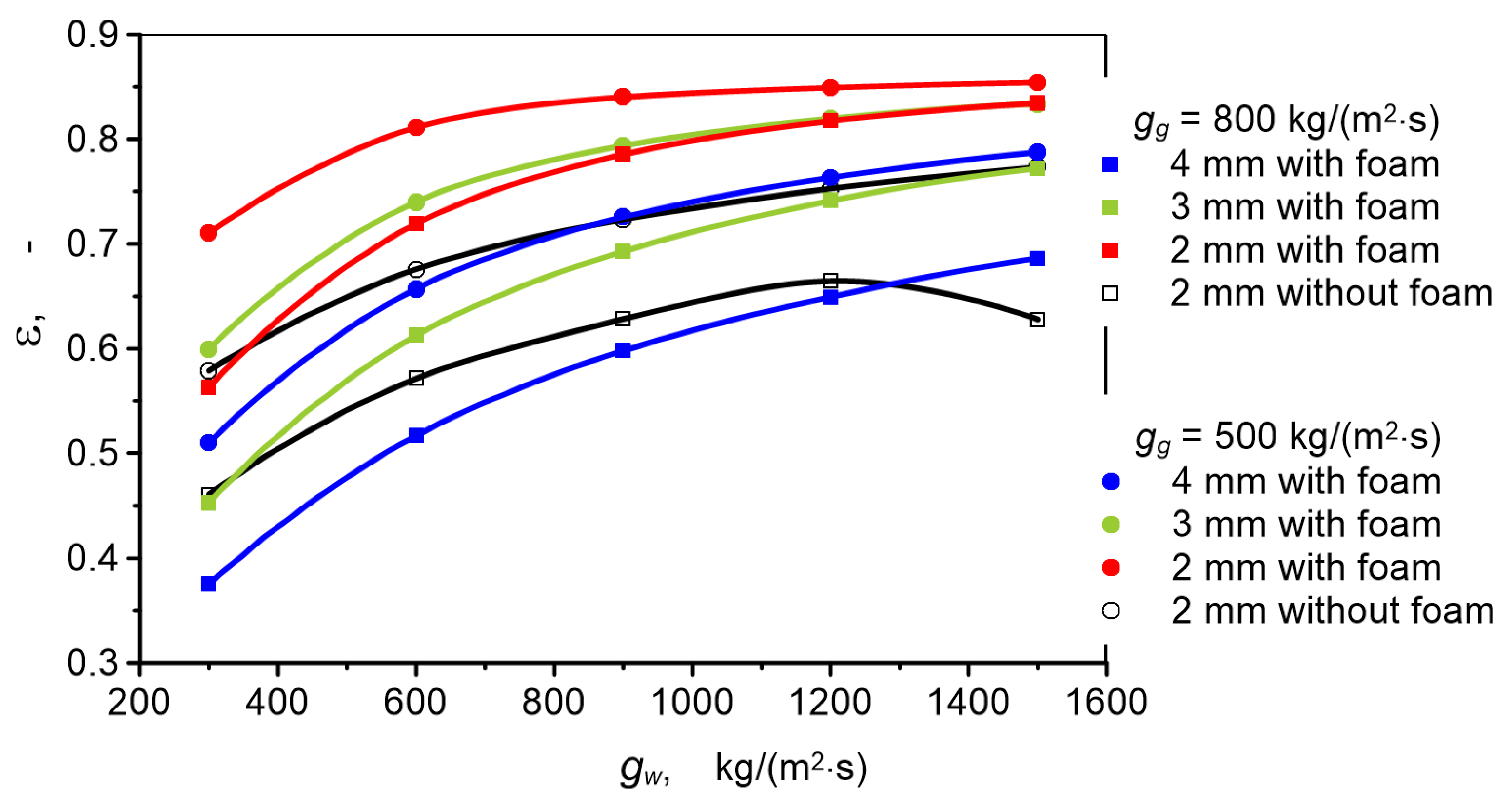
The heat exchanger with a 2 mm diameter channel with metal foam is also characterized by the highest thermal effectiveness ε among all studied cases (Figure 23). The thermal effectiveness is the actual heat transfer rate divided by the theoretical maximum heat transfer rate. As shown in Figure 23 and Figure 24, under all flow conditions, heat transfer effectiveness for a 2 mm channel with metal foam is 0.076–0.207 higher than in a 2 mm channel without foam. In the case of a 3 mm channel, this difference is smaller and amounts to 0.021–0.077 in favor of the 3 mm channel, although when gg = 500 and 800 kg/(m2·s), heat transfer effectiveness is lower than in the 2 mm channel. Heat transfer in a 4 mm diameter channel filled with foam occurs with lower effectiveness than in a 2 mm channel without foam throughout the entire research range.
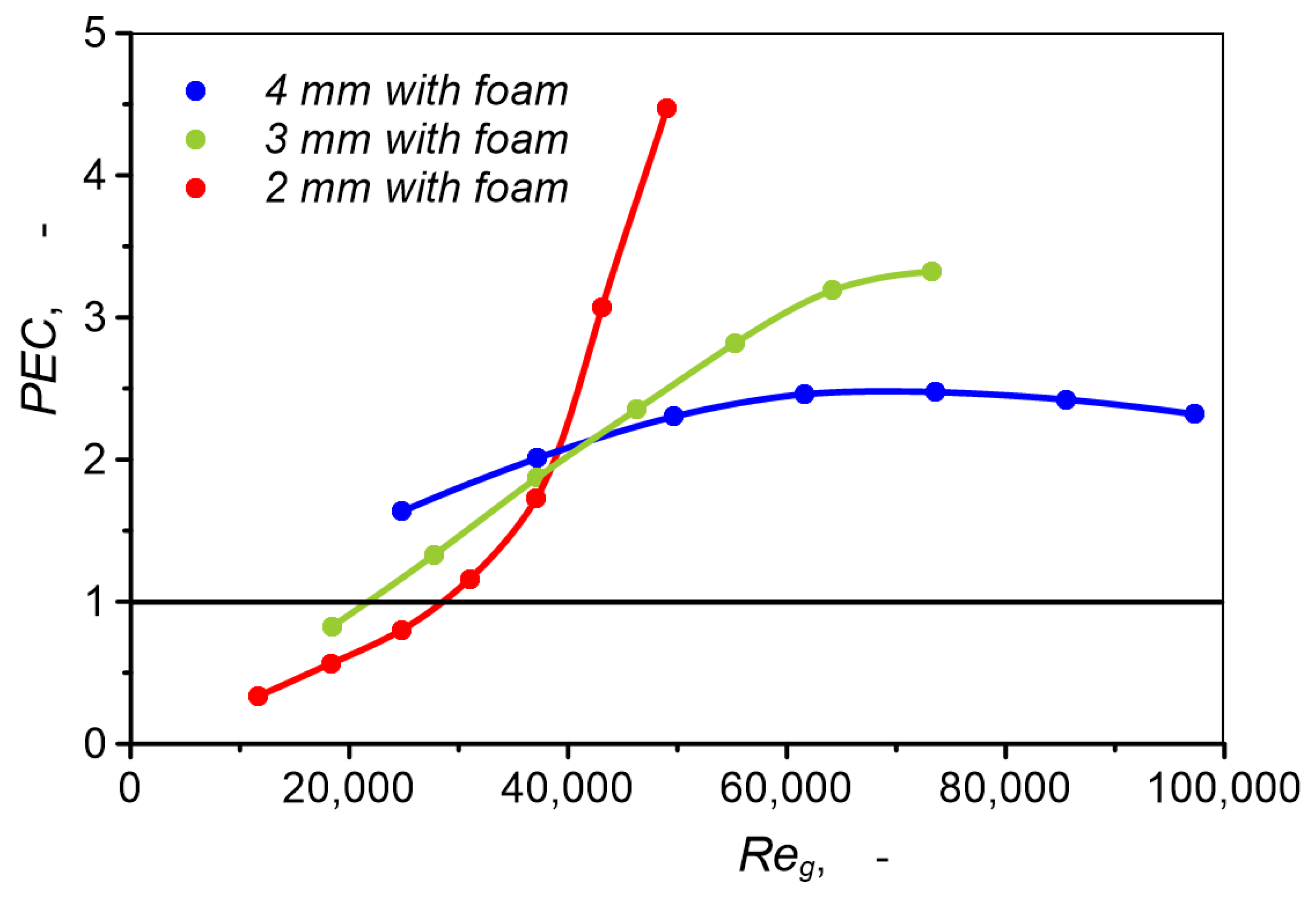
Data presented in Figure 25 indicate that carbon dioxide cooling in a heat exchanger with channels filled with metal foam is characterized by higher thermal–hydraulic performance than a heat exchanger without foam, provided that high turbulence of gas flow is required. When the Reynolds number is less than approximately 30,000, the PEC value may be less than 1, which means that the heat exchange with metal foam has worse thermal–hydraulic parameters. The PEC value depends significantly on channel diameter. Maximum value PEC = 4.47 was recorded for a 2 mm channel when the maximum gas flux was cooled. In the case of a 4 mm channel, PEC varies from 1.63 to 2.48.
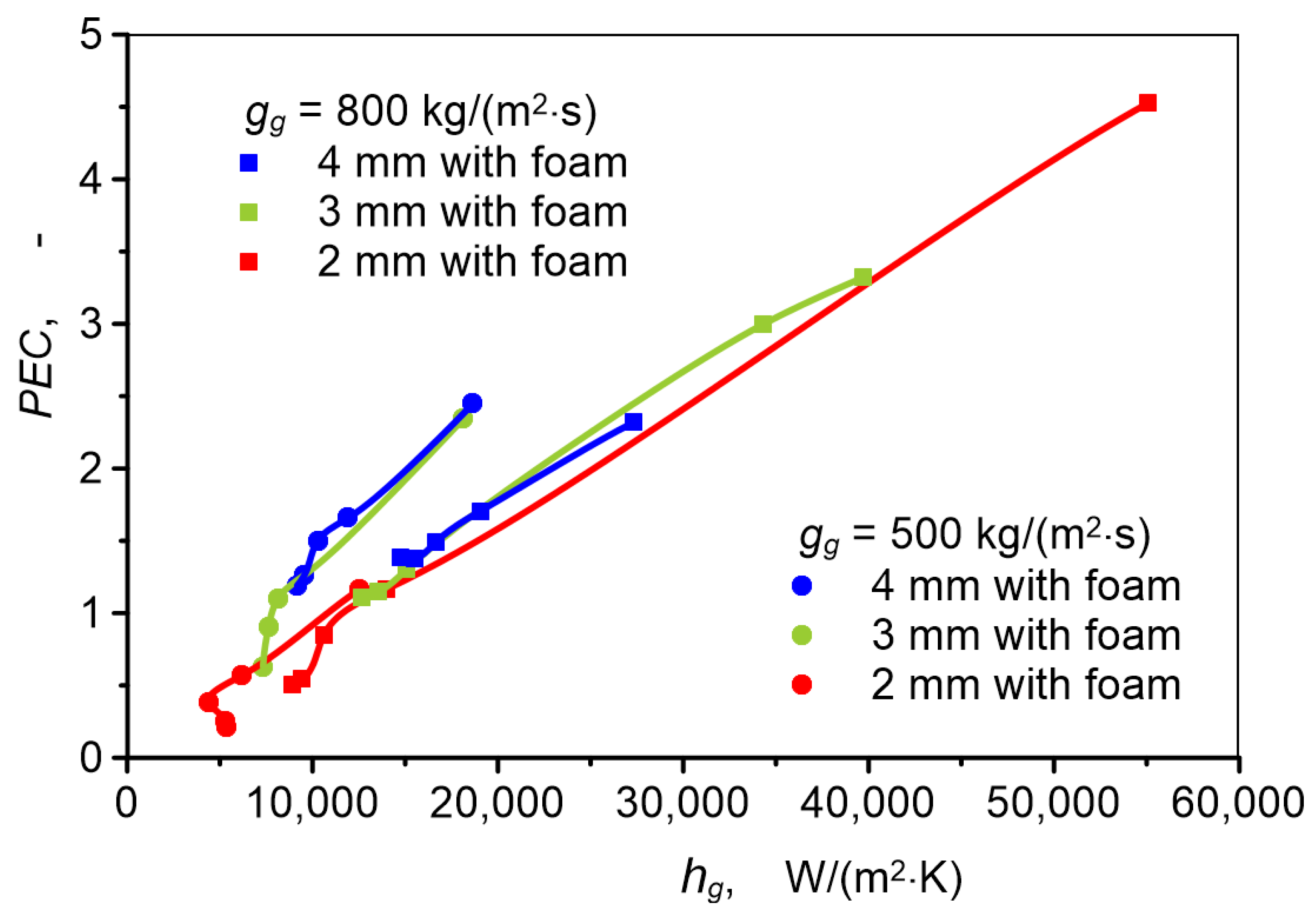
The trend of PEC changes for individual channels is quite diverse and does not allow for unambiguous interpretation of results and formulation of generalized conclusions. Based on Figure 26, however, it can be stated that regardless of channel diameter, in the range of conducted research, the PEC achieves a value greater than 1 when the heat transfer coefficient exceeds 12,000. At high heat transfer intensity, thermal–hydraulic performance increases linearly with increasing heat transfer coefficient.
Many authors of studies argue that printed circuit heat exchangers with channels other than straight channels have better operating parameters, especially exchangers with zigzag and airfoil channels. For this reason, the tested heat exchanger with channels filled with metal foam was compared with these two types of PCHE heat exchangers. The comparison was based on the Colburn j-factor (Equation (22)), the Nusselt number, and the friction factor, which were determined using the correlations listed in Table 6.
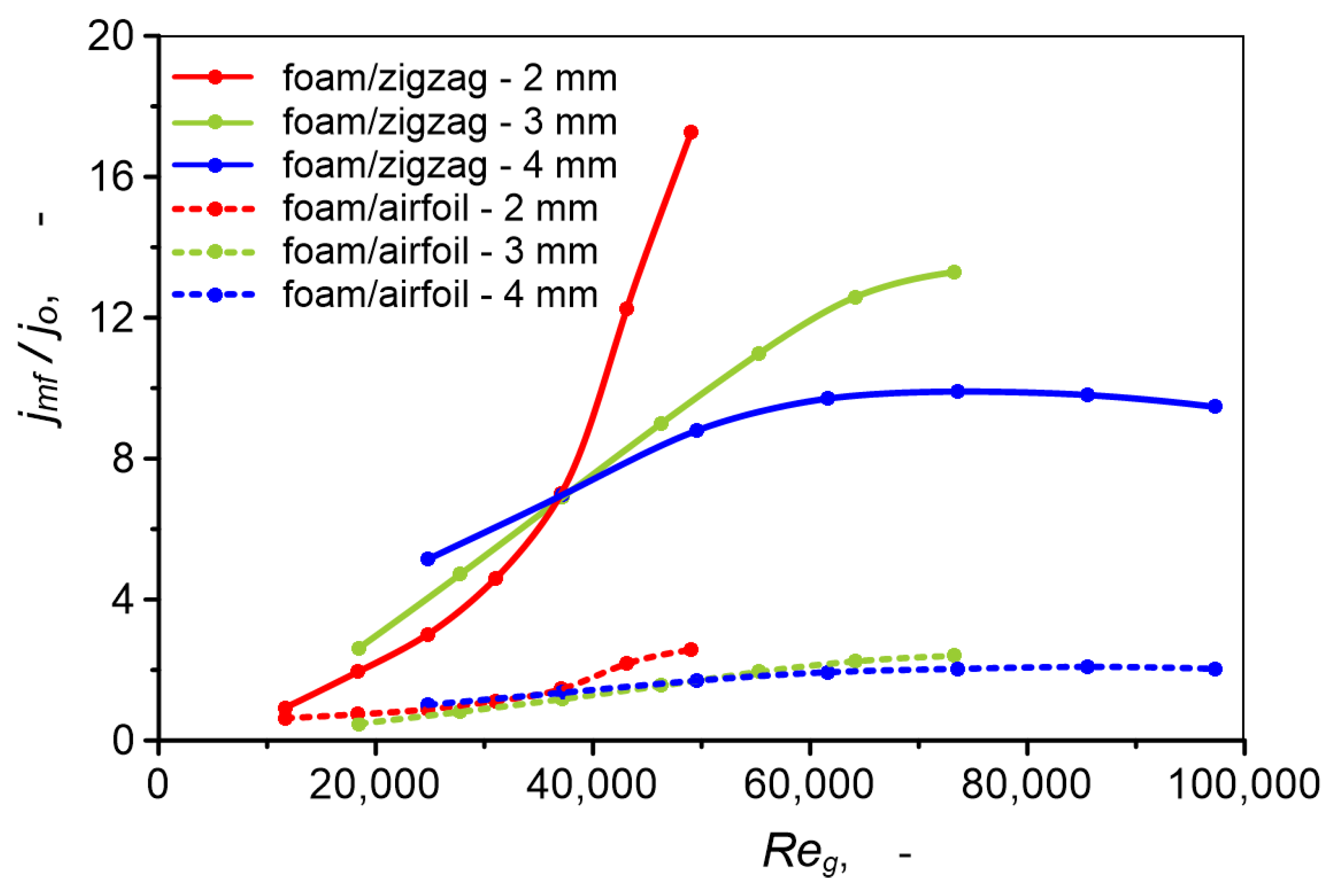
Figure 27 shows the ratio of the heat transfer performance of a metal foam heat exchanger to the heat transfer performance of a heat exchanger with zigzag channels and airfoil plates. This ratio is denoted as jmf/jo, where jo refers to exchangers with zigzag channels and airfoil plates. As can be seen, the heat transfer performance of a PCHE heat exchanger with metal foam can be up to several times greater than that of heat exchangers with zigzag channels and up to 2.6 times greater than that of a heat exchanger with airfoil plates. The advantage of a heat exchanger with metal foam increases with the Reynolds number. At the lowest Reynolds numbers, an airfoil plate heat exchanger may have a heat transfer performance greater than that of a PCHE with metal foam (jmf/jo < 1). The influence of the channel diameter is also visible. The PCHE heat exchanger with the smallest diameter channels has the highest efficiency. The very high heat transfer performance of PCHE heat exchangers with metal foam is the result of heat transport at a very small temperature difference between the gas and the channel wall. The heat transfer coefficient calculated for such conditions is very high, which is reflected in the Colburn j-factor value. Despite the high Colburn j-factor value, the heat flux in PCHE heat exchangers with metal foam is only 33% to 63% higher than in PCHE heat exchangers without foam (Figure 18).
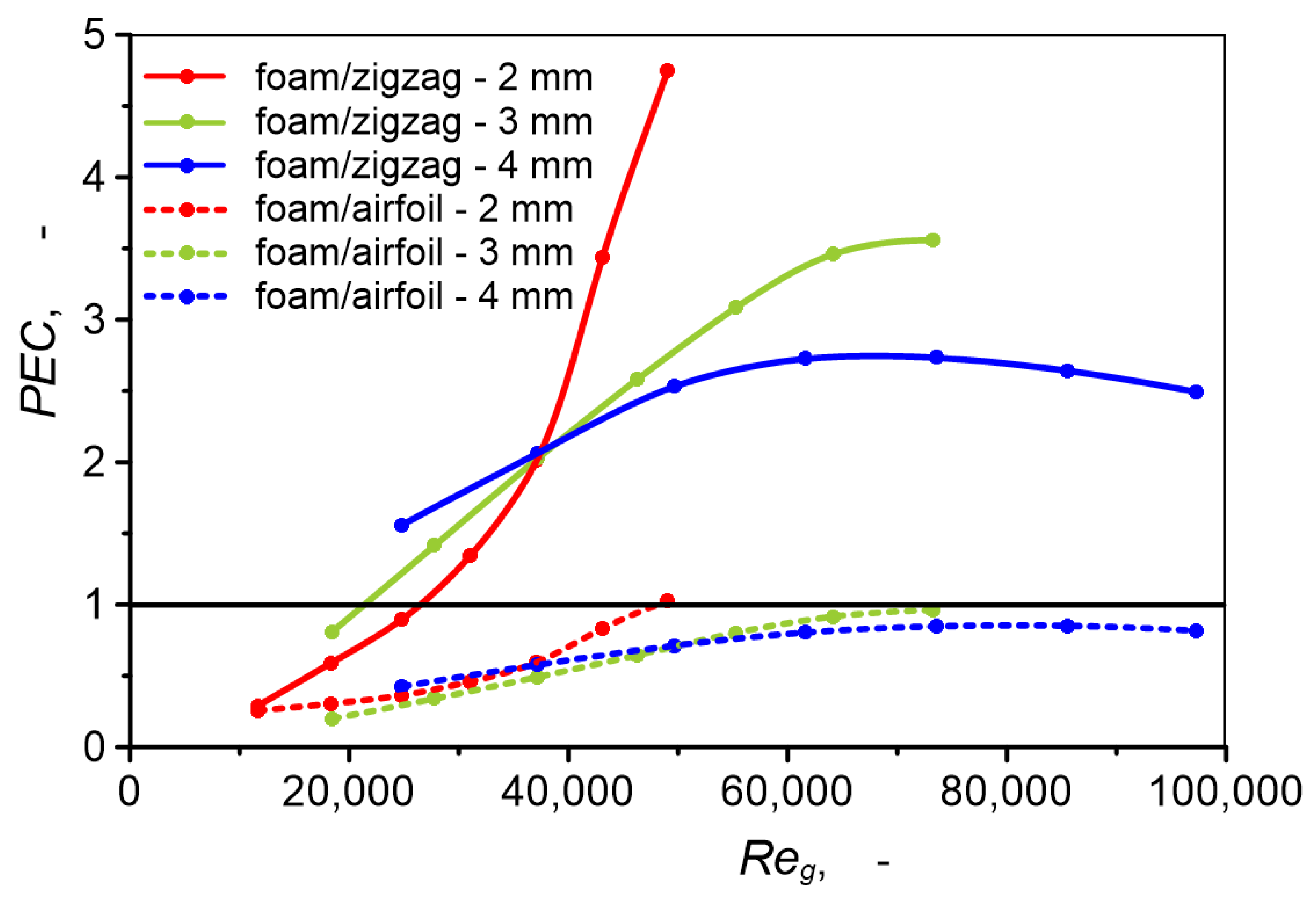
Airfoil PCHE heat exchangers are characterized by a relatively low pressure drop. The very high pressure drop in the flow through metal foams means that PCHE heat exchangers with metal foam have less positive thermal–hydraulic performance. As can be seen in Figure 28, when comparing a metal foam heat exchanger with an airfoil PCHE heat exchanger (foam/airfoil), the PEC value is less than 1 for all three channels.

4. Conclusions

Printed circuit heat exchangers are one of many types of heat exchangers used in industrial processes. Compact construction and materials used provide these heat exchangers with very high mechanical strength and thermal resistance, which predisposes them for operation under very difficult conditions, including very high pressure and extremely low or high temperatures. Moreover, printed circuit heat exchangers are characterized by very large unit heat transfer surface areas and small dimensions. These features cause growing interest in these heat exchangers as an alternative to other types of heat exchangers. A typical example of printed circuit heat exchanger application is cooling and heating of supercritical gases in the Brayton cycle. Research work aimed at improving the operational parameters of printed circuit heat exchangers is constantly being conducted. In recent years, the subject of research work most often seems to be the influence of flow channel shape on thermal–hydraulic performance of printed circuit heat exchangers.
This paper is the first report describing work on improving printed circuit heat exchangers by using open-cell metal foam in their construction. The aim of the conducted work was to determine how placing metal foam inside gas channels of printed circuit heat exchangers affects the performance of a supercritical carbon dioxide precooler cooled by water. The significance of channel diameter was also determined.
Due to the conceptual stage of work, research was conducted numerically using CFD Ansys Fluent software. Numerical simulations were conducted using a unit, repeatable geometric model of two adjacent straight channels with semicircular cross-sections. For comparative purposes, simulations of supercritical carbon dioxide cooling in an unfilled channel and in channels filled with metal foam were conducted. Studies were performed for five different cold medium mass fluxes and seven hot fluid fluxes, while maintaining their constant initial temperatures. The effect of using metal foam was evaluated based on typical parameters characterizing thermal-flow phenomena and heat exchanger performance. Analysis of the obtained results allows the formulation of the conclusions presented below.
  • Placing open-cell metal foam in the gas channel causes an increase in heat flux released by the cooled gas compared to cooling in an empty channel of the same diameter. Depending on mass flux, this difference ranges from 33 to 63% in favor of the channel with metal foam.
  • Heat flux increases with channel diameter. In the case of the presented studies, 20–40% higher heat flux was obtained in a 4 mm diameter channel with metal foam than in a 2 mm channel with metal foam and was 60–84% higher than in a 2 mm channel without foam.
  • Increasing channel diameter leads to a decrease in unit heat transfer surface area, therefore the most favorable ratio of heat transfer rate to heat exchanger volume (qgV) is characterized by a heat exchanger with 2 mm diameter channels with metal foam.
  • In all analyzed cases, the heat transfer coefficient in channels filled with metal foam achieves significantly higher values than in channels without foam. This difference increases with the mass flux of cooled carbon dioxide. Moreover, the influence of gas mass flux on the heat transfer coefficient value is stronger in a 2 mm channel than in 3 and 4 mm channels. In the case of a 2 mm channel with metal foam, the maximum heat transfer coefficient value is 54.56 kW/(m2·K). For 3 and 4 mm channels, the highest heat transfer coefficient values are 39.69 and 27.33 kW/(m2·K), respectively.
  • Heat transfer effectiveness of the studied system with metal foam in a 2 mm diameter channel is 7.6% to 20.7% higher than in the case of a channel without metal foam. For a 3 mm channel, heat transfer effectiveness is lower than for a 2 mm channel with filling. The lowest heat transfer effectiveness characterizes heat transfer in a 4 mm channel. In this case, heat transfer effectiveness in a channel with foam is several percent lower than in an empty channel.
  • Pressure drop of supercritical carbon dioxide flow through channels filled with metal foam, in the range of conducted studies, is 45–82 times higher than pressure drop in an empty channel and depends slightly on channel diameter because metal foam parameters have the decisive influence on pressure drop. Increasing channel diameter does not cause a clear decrease in pressure drop and does not contribute to improving hydraulic performance.
  • Overall thermal–hydraulic performance of the studied systems strongly depends on flow conditions, expressed by the Reynolds number, heat transfer intensity, and channel diameter. The highest thermal–hydraulic performance is characterized by a 2 mm channel with metal foam, for which the maximum PEC value is 4.47. Under the same heat transfer conditions, PEC for 3 and 4 mm channels is approximately two times lower. The course of thermal–hydraulic performance changes as a function of the Reynolds number is significantly different for individual channels.
  • PCHE heat exchangers with metal foam channels have higher heat transfer performance than PCHE heat exchangers with zigzag channels and airfoil PCHE heat exchangers. Due to high pressure drop, PCHE heat exchangers with metal foam have lower thermal–hydraulic performance than airfoil PCHE heat exchangers.
In summary, placing metal foam in gas channels of printed circuit heat exchangers causes a greater temperature change in the cooled gas than in the case of the same heat exchanger without metal foam and is fully justified when the degree of cooling or heating of the medium is a priority over heat transfer efficiency. Thermal–hydraulic performance of a heat exchanger with metal foam is higher than in the case of an analogous heat exchanger without metal foam, in a wide range of tested heat transfer conditions, despite very high gas pressure drop through foam-filled channels. In some cases, integrating foam with the gas channel results in decreased thermal–hydraulic performance (PEC < 1), especially when a relatively small gas mass flux is being cooled. The collected information does not allow formulation of sufficiently unambiguous and general conclusions in this regard. This concerns, among others, the influence of channel diameter on thermal–hydraulic performance of heat exchangers with metal foam. Depending on flow conditions, printed circuit heat exchangers with larger channels filled with metal foam may be characterized by higher or lower thermal–hydraulic performance than the corresponding heat exchanger with smaller empty channels.
The results of the research presented in this paper confirm the validity of the concept of incorporating metal foam into the gas channels of printed circuit heat exchangers in order to improve their thermal–hydraulic performance. However, due to the purely numerical nature of the work carried out, the results obtained should be treated as an indication of probable and promising possibilities for improving PCHE heat exchangers. The author of the paper, based on the current state of knowledge and the methodology of other similar numerical works presented in the literature, has made every effort to ensure that the results obtained are as reliable as possible. Nevertheless, further work is necessary, especially experimental work, which will allow for the verification of the presented results and will be aimed at optimizing heat transfer conditions and determining guidelines for using metal foams in printed circuit heat exchangers. Further work should be conducted in a broader range of heat exchanger operating condition changes, using foams with diversified structural parameters.

Funding

This research received no external funding.

Data Availability Statement

The original contributions presented in this study are included in the article. Further inquiries can be directed to the corresponding author.

Conflicts of Interest

The authors declare no conflict of interest.

Nomenclature

aHExheat exchanger specific surface area, m2/m3
asfmetal foam specific surface area, m2/m3
cspecific heat, J/(kg·K)
CFfoam inertial coefficient, m
dccell diameter, m
dchannel size, m
dhhydraulic diameter, m
dldiameter of foam ligament, m
dppore diameter, m
fFanning friction factor, –
gmass flux, kg/(m2·s)
hheat transfer coefficient, W/(m2·K)
jColburn j-factor, –
ksskeleton thermal conductivity coefficient, W/(m·K)
keffeffective thermal conductivity coefficient, W/(m·K)
Kfoam permeability, m2
Lchannel length, m
mmass flow rate, kg/s
NuNuselt number, –
PECThermal–hydraulic performance, –
PrPrandtl number, –
ReReynolds number, –
qheat flux, W/m2
qVunit heat flux (heat transfer rate per unit volume of the heat exchanger), W/m3
Qheat transfer rate, W
ttemperature, °C
vvelocity, m/s
Greek Symbols
Δp/Δlunit pressure drop, Pa/m
Δttemperature difference, K
εheat transfer effectiveness, –
ϕporosity of metal foam, –
μviscosity, Pa∙s
Δdensity, kg/m3
ωpore density, PPI
Subscripts
ffluid (water or sCO2)
ggas (sCO2)/hot fluid
ininlet condition
mfmetal foam
outoutlet condition
ssolid
swchannel wall
wwater/cold fluid

References

  1. Fu, X.; Zhang, R.; Shi, L.; Wang, Y.; Li, Q.; Cai, W. Micro Segment Analysis and Machine Learning Prediction for Thermal-Hydraulic Parameters of Propane Condensation Flow in a PCHE Straight Channel. Energy 2024, 310, 133261. [Google Scholar] [CrossRef]
  2. Ahmed, M.M.; Ehsan, M.M. Design and Off-Design Performance Analysis of a Zigzag Channeled Precooler for Indirect Cooling System of Supercritical CO2 Recompression Cycle Incorporated with a Flow-Bypass System. Appl. Therm. Eng. 2023, 226, 120321. [Google Scholar] [CrossRef]
  3. Baik, S.; Kim, S.G.; Lee, J.; Lee, J.I. Study on CO2—Water Printed Circuit Heat Exchanger Performance Operating under Various CO2 Phases for S-CO2 Power Cycle Application. Appl. Therm. Eng. 2017, 113, 1536–1546. [Google Scholar] [CrossRef]
  4. Cheng, K.; Zhou, J.; Zhang, H.; Huai, X.; Guo, J. Experimental Investigation of Thermal-Hydraulic Characteristics of a Printed Circuit Heat Exchanger Used as a Pre-Cooler for the Supercritical CO2 Brayton Cycle. Appl. Therm. Eng. 2020, 171, 115116. [Google Scholar] [CrossRef]
  5. Jin, F.; Chen, D.; Hu, L.; Huang, Y.; Zeng, H.; Wang, J. Thermo-Hydraulic Performance of Printed Circuit Heat Exchanger as Precooler in Supercritical CO2 Brayton Cycle. Appl. Therm. Eng. 2022, 210, 118341. [Google Scholar] [CrossRef]
  6. Jin, F.; Yuan, D.; Chen, D.; Hu, L.; Huang, Y.; Bu, S. Experimental Study on Cooling Heat Transfer Performance of Supercritical CO2 in Zigzag Printed Circuit Heat Exchanger. Int. J. Heat Mass Transf. 2023, 215, 124538. [Google Scholar] [CrossRef]
  7. Li, H.; Zhang, Y.; Zhang, L.; Yao, M.; Kruizenga, A.; Anderson, M. PDF-Based Modeling on the Turbulent Convection Heat Transfer of Supercritical CO2 in the Printed Circuit Heat Exchangers for the Supercritical CO2 Brayton Cycle. Int. J. Heat Mass Transf. 2016, 98, 204–218. [Google Scholar] [CrossRef]
  8. Lee, S.W.; Lee, Y.; Lee, Y.; Jo, H.J. Condensation Heat Transfer and Applicability Assessment of a Printed Circuit Heat Exchanger as a Condenser in a Cryogenic CO2 Capture and Storage System. Appl. Therm. Eng. 2025, 261, 125133. [Google Scholar] [CrossRef]
  9. Ren, Z.; Zhao, C.R.; Jiang, P.X.; Bo, H.L. Investigation on Local Convection Heat Transfer of Supercritical CO2 during Cooling in Horizontal Semicircular Channels of Printed Circuit Heat Exchanger. Appl. Therm. Eng. 2019, 157, 113697. [Google Scholar] [CrossRef]
  10. Ren, Y.; Jiang, R.; Wang, P.; Wu, W.; Yang, Y.; Yang, Q. Experimental Study of a Rectangular Microchannel Printed Circuit Heat Exchanger Using Supercritical Carbon Dioxide and Water Cooling. Appl. Therm. Eng. 2025, 262, 125230. [Google Scholar] [CrossRef]
  11. Han, Z.; Guo, J.; Huai, X. Theoretical Analysis of a Novel PCHE with Enhanced Rib Structures for High-Power Supercritical CO2 Brayton Cycle System Based on Solar Energy. Energy 2023, 270, 126928. [Google Scholar] [CrossRef]
  12. Yin, D.; Zhou, Y.; Guo, X.; Wang, D. Numerical Analysis of Wavy PCHEs in Supercritical CO2/Propane Mixture Brayton Cycle. Appl. Therm. Eng. 2023, 235, 121346. [Google Scholar] [CrossRef]
  13. Saeed, M.; Ali Awais, A.; Berrouk, A.S. CFD Aided Design and Analysis of a Precooler with Zigzag Channels for Supercritical CO2 Power Cycle. Energy Convers. Manag. 2021, 236, 114029. [Google Scholar] [CrossRef]
  14. Khoshvaght-Aliabadi, M.; Ghodrati, P.; Mortazavi, H.; Kang, Y.T. Numerical Analysis of Heat Transfer and Flow Characteristics of Supercritical CO2-Cooled Wavy Mini-Channel Heat Sinks. Appl. Therm. Eng. 2023, 226, 120307. [Google Scholar] [CrossRef]
  15. Moisseytsev, A.; Sienicki, J.J. Investigation of Alternative Layouts for the Supercritical Carbon Dioxide Brayton Cycle for a Sodium-Cooled Fast Reactor. Nucl. Eng. Des. 2009, 239, 1362–1371. [Google Scholar] [CrossRef]
  16. Zhou, Y.; Yin, D.; Guo, X.; Dong, C. Numerical Analysis of the Thermal and Hydraulic Characteristics of CO2/Propane Mixtures in Printed Circuit Heat Exchangers. Int. J. Heat Mass Transf. 2022, 185, 122434. [Google Scholar] [CrossRef]
  17. Lee, S.W.; Shin, S.M.; Chung, S.K.; Jo, H.J. Evaluation of Thermal-Hydraulic Performance and Economics of Printed Circuit Heat Exchanger (PCHE) for Recuperators of Sodium-Cooled Fast Reactors (SFRs) Using CO2 and N2 as Working Fluids. Nucl. Eng. Technol. 2022, 54, 1874–1889. [Google Scholar] [CrossRef]
  18. Ma, T.; Zhang, P.; Deng, T.; Ke, H.; Lin, Y.; Wang, Q. Thermal-Hydraulic Characteristics of Printed Circuit Heat Exchanger Used for Floating Natural Gas Liquefaction. Renew. Sustain. Energy Rev. 2021, 137, 110606. [Google Scholar] [CrossRef]
  19. Peng, Z.R.; Zheng, Q.Y.; Chen, J.; Yu, S.C.; Zhang, X.R. Numerical Investigation on Heat Transfer and Pressure Drop Characteristics of Coupling Transcritical Flow and Two-Phase Flow in a Printed Circuit Heat Exchanger. Int. J. Heat Mass Transf. 2020, 153, 119557. [Google Scholar] [CrossRef]
  20. Zhang, P.; Ma, T.; Ke, H.; Wang, W.; Lin, Y.; Wang, Q. Numerical Investigation on Local Thermal Characteristics of Printed Circuit Heat Exchanger for Natural Gas Liquefication. Energy Procedia 2019, 158, 5408–5413. [Google Scholar] [CrossRef]
  21. Li, S.; Zhao, Z.; Zhang, Y.; Xu, H.; Zeng, W. Experimental and Numerical Analysis of Condensation Heat Transfer and Pressure Drop of Refrigerant R22 in Minichannels of a Printed Circuit Heat Exchanger. Energies 2020, 13, 6589. [Google Scholar] [CrossRef]
  22. Zhao, Z.; Zhang, Y.; Chen, X.; Ma, X.; Yang, S.; Li, S. A Numerical Study on Condensation Flow and Heat Transfer of Refrigerant in Minichannels of Printed Circuit Heat Exchanger. Int. J. Refrig. 2019, 102, 96–111. [Google Scholar] [CrossRef]
  23. Yoo, J.W.; Nam, C.W.; Yoon, S.H. Experimental Study of Propane Condensation Heat Transfer and Pressure Drop in Semicircular Channel Printed Circuit Heat Exchanger. Int. J. Heat Mass Transf. 2022, 182, 121939. [Google Scholar] [CrossRef]
  24. Zhang, Z.; Chen, L.; Lv, H.; Li, S.; Hou, Y. Experimental and Numerical Investigation of a High-Effectiveness Cryogenic PCHE for Space 80 K Brayton Cryocooler. Int. J. Refrig. 2025, 176, 26–39. [Google Scholar] [CrossRef]
  25. Tian, Z.; Zhou, X.; Zhao, B.; Shen, W.; Peng, H. Comparative Analyses on Freezing Risk and Novel Anti-Freezing Structure for PCHEs as SLNG Vaporizer. Int. J. Heat Mass Transf. 2024, 229, 125719. [Google Scholar] [CrossRef]
  26. Tian, Z.; Wang, C.; Jiang, T.; Zhao, B.; Shen, W.; Peng, H. Experimental Study and Dynamic Response Analysis of Thermal–Hydraulic Characteristics in Zigzag PCHE at Ultra-Low Temperature. Appl. Therm. Eng. 2025, 268, 125897. [Google Scholar] [CrossRef]
  27. Yang, L.; Deng, C.; Li, W.; Zhao, B.; Li, Q.; Cai, W. Study on the Similarity Criterions for Trans-Critical Flow and Heat Transfer of Methane and Nitrogen in PCHE. Int. Commun. Heat Mass Transf. 2024, 159, 107993. [Google Scholar] [CrossRef]
  28. Chen, J.; Du, W.; Cheng, K.; Li, X.; Guo, J.; Lv, P.; Dong, H. Design Analysis of a Hybrid Printed Circuit Heat Exchanger for Precooling in Hydrogen Refueling Station. Int. Commun. Heat Mass Transf. 2025, 163, 108765. [Google Scholar] [CrossRef]
  29. Ding, L.; Wang, X.; Niu, M.; Li, B.; Wang, W. Numerical Investigation of Supercritical Flow and Heat Transfer Mechanism in Printed Circuit Heat Exchanger (PCHE) Channels. Int. J. Hydrogen Energy 2024, 62, 31–47. [Google Scholar] [CrossRef]
  30. Huisseune, H.; De Schampheleire, S.; Ameel, B.; De Paepe, M. Comparison of Metal Foam Heat Exchangers to a Finned Heat Exchanger for Low Reynolds Number Applications. Int. J. Heat Mass Transf. 2015, 89, 1–9. [Google Scholar] [CrossRef]
  31. Kim, D.Y.; Sung, T.H.; Kim, K.C. Application of Metal Foam Heat Exchangers for a High-Performance Liquefied Natural Gas Regasification System. Energy 2016, 105, 57–69. [Google Scholar] [CrossRef]
  32. Bamorovat Abadi, G.; Moon, C.; Kim, K.C. Experimental Study on Single-Phase Heat Transfer and Pressure Drop of Refrigerants in a Plate Heat Exchanger with Metal-Foam-Filled Channels. Appl. Therm. Eng. 2016, 102, 423–431. [Google Scholar] [CrossRef]
  33. Tamkhade, P.K.; Lande, R.D.; Gurav, R.B.; Lele, M.M. Investigations on Tube in Tube Metal Foam Heat Exchanger. Mater. Today Proc. 2023, 72, 951–957. [Google Scholar] [CrossRef]
  34. Zaib, F.; Ganesan, P.; Zaharinie, T.; Chen, Z.; Naganthran, K. Heat Transfer Performance of a Compact Heat Exchanger Based on Metal Foam and Thermal Interface Material (TIM). Int. J. Heat Mass Transf. 2024, 231, 125861. [Google Scholar] [CrossRef]
  35. Jadhav, P.H.; Gnanasekaran, N.; Mobedi, M. Analysis of Functionally Graded Metal Foams for the Accomplishment of Heat Transfer Enhancement under Partially Filled Condition in a Heat Exchanger. Energy 2023, 263, 125691. [Google Scholar] [CrossRef]
  36. Dyga, R.; Troniewski, L. Convective Heat Transfer for Fluids Passing through Aluminum Foams. Arch. Thermodyn. 2015, 36, 139–156. [Google Scholar] [CrossRef]
  37. Dyga, R.; Brol, S. Investigation of a Modular High-Pressure Heat Exchanger with Metal Foam Packing for a Pneumatic–Hydraulic Drive. Materials 2024, 17, 5557. [Google Scholar] [CrossRef]
  38. Dyga, R.; Brol, S. Pressure Drops in Two-Phase Gas–Liquid Flow through Channels Filled with Open-Cell Metal Foams. Energies 2021, 14, 2419. [Google Scholar] [CrossRef]
  39. Yu, P.; Liu, H.; Xue, J.; Zhang, Y.; Che, D. Thermo-Hydraulic Performance of a Cryogenic Printed Circuit Heat Exchanger for Liquid Air Energy Storage. Appl. Therm. Eng. 2023, 219, 119429. [Google Scholar] [CrossRef]
  40. Yang, X.; Wang, W.; Wang, Z.; Ma, F. Simulation of Pre-Cooling in a High Pressure Hydrogen Refueling Station for Operation Optimization. Int. J. Hydrogen Energy 2024, 86, 434–444. [Google Scholar] [CrossRef]
  41. Hu, H.; Li, Y.; Lei, R.; Xie, Y.; Li, J. Numerical Investigation on Flow Condensation in Zigzag Channel of Printed Circuit Heat Exchanger. Appl. Therm. Eng. 2024, 252, 123645. [Google Scholar] [CrossRef]
  42. Ansys Fluent User’s Guide v. 2024/R2. Available online: https://ansyshelp.ansys.com/account/secured?returnurl=/Views/Secured/corp/v242/en/flu_th/flu_th.html (accessed on 2 June 2025).
  43. Duan, X.; Liu, X.; Huang, X.; Wang, Y.; Ding, C. A Novel Design for Performance Enhancement in Sandwich Heat Transfer Unit with Partially Filled Metal Foam. Int. Commun. Heat Mass Transf. 2025, 165, 109086. [Google Scholar] [CrossRef]
  44. Torres-Madroñero, J.L.; Lopera-Escobar, J.; Marulanda-Zapata, L.; Fernández-Morales, P.; Nieto-Londoño, C. Numerical Analysis of Non-Regular and Regular Metal Foam Performance in Heat Transfer Enhancing Applications. Appl. Therm. Eng. 2025, 273, 126562. [Google Scholar] [CrossRef]
  45. Settar, A.; Nebbali, R.; Madani, B.; Abboudi, S. Numerical Investigation of Convective Heat Transfer in a Plane Channel Filled with Metal Foam under Local Thermal Non-Equilibrium. Mech. Ind. 2015, 16, 504. [Google Scholar] [CrossRef]
  46. Xiong, J.; Sun, J.; Chen, Y.; Nie, Z. Study on the Flow and Heat Transfer Characteristics inside High-Porosity Open-Cell Copper Foams: Experimental and Numerical Explorations. Int. J. Heat Fluid Flow. 2024, 109, 109499. [Google Scholar] [CrossRef]
  47. Si, W.; Fu, C.; Wu, X.; Deng, X.; Yuan, P.; Huang, Z.; Yang, J. Numerical Study of Flow and Heat Transfer in the Air-Side Metal Foam Partially Filled Channels of Panel-Type Radiator under Forced Convection. Open Phys. 2025, 23, 20250121. [Google Scholar] [CrossRef]
  48. Hassan, A.M.; Alwan, A.A.; Hamzah, H.K. Metallic Foam with Cross Flow Heat Exchanger: A Review of Parameters, Performance, and Challenges. Heat Transf. 2022, 52, 2618–2650. [Google Scholar] [CrossRef]
  49. Xu, H.; Gong, L.; Huang, S.; Xu, M. Flow and Heat Transfer Characteristics of Nanofluid Flowing through Metal Foams. Int. J. Heat Mass Transf. 2015, 83, 399–407. [Google Scholar] [CrossRef]
  50. Xu, H.J.; Gong, L.; Zhao, C.Y.; Yang, Y.H.; Xu, Z.G. Analytical Considerations of Local Thermal Non-Equilibrium Conditions for Thermal Transport in Metal Foams. Int. J. Therm. Sci. 2015, 95, 73–87. [Google Scholar] [CrossRef]
  51. Zukauskas, A. Convective Heat Transfer in Humans. In Handbook of Single-Phase Convective Heat Transfer; Kakac, S., Shah, R.K., Aung, W., Eds.; Wiley: New York, NY, USA, 1987. [Google Scholar]
  52. Bhattacharya, A.; Calmidi, V.V.; Mahajan, R.L. Thermophysical Properties of High Porosity Metal Foams. Int. J. Heat Mass Transf. 2002, 45, 1017–1031. [Google Scholar] [CrossRef]
  53. Dyga, R.; Płaczek, M.; Witczak, S.; Czernek, K. Analysis of Flow Through the Entry Region of a Channel with Metal Foam Packing. In Practical Aspects of Chemical Engineering: Selected Contributions from PAIC 2017; Springer: Cham, Switzerland, 2018. [Google Scholar]
  54. Kim, I.H.; NO, H.C. Thermal–Hydraulic Physical Models for a Printed Circuit Heat Exchanger Covering He, He–CO2 Mixture, and Water Fluids Using Experimental Data and CFD. Exp. Therm. Fluid Sci. 2013, 48, 213–221. [Google Scholar] [CrossRef]
  55. Pidaparti, S.R.; Anderson, M.H.; Ranjan, D. Experimental Investigation of Thermal-Hydraulic Performance of Discontinuous Fin Printed Circuit Heat Exchangers for Supercritical CO2 Power Cycles. Exp. Therm. Fluid Sci. 2019, 106, 119–129. [Google Scholar] [CrossRef]
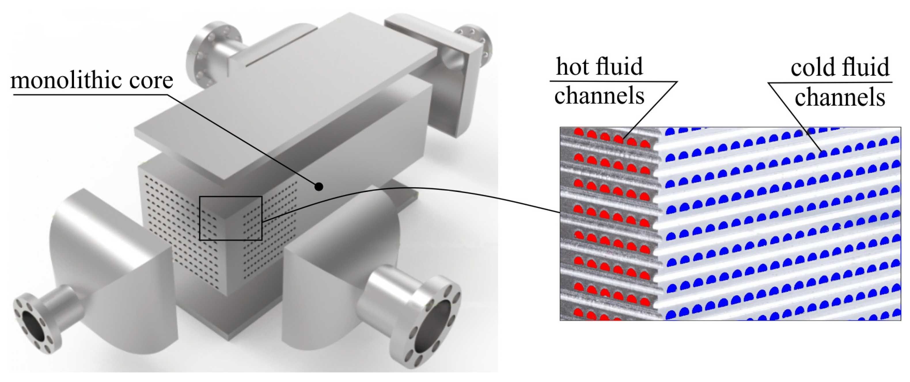
Figure 1. Standard design of printed circuit heat exchangers.
Energies 18 04736 g001
Figure 2. Channel types of PCHE: (a) straight, (b) zigzag, (c) wavy.
Energies 18 04736 g002
Figure 3. Standard way of pumping fluids in a PCHE.
Energies 18 04736 g003
Figure 4. CFD simulation model—heat exchanger core.
Energies 18 04736 g004
Figure 5. CFD simulation model—computational domain and boundary conditions.
Energies 18 04736 g005
Figure 6. (a) Mesh in the solid and fluid regions, (b) inflation layer in the fluid zone.
Energies 18 04736 g006
Figure 7. Grid independence verification.
Energies 18 04736 g007
Figure 8. Gas streamlines (gg = 700 kg/(m2·s).
Energies 18 04736 g008
Figure 9. Velocity field of sCO2 in flow through: (a) 2 mm diameter channel without copper foam, (b) and with copper foam. Gas mass flux gg = 700 kg/(m2·s).
Energies 18 04736 g009
Figure 10. Comparison of changes in local sCO2 velocity in the channel axis as a function of channel length, for channels with copper foam and an empty channel.
Energies 18 04736 g010
Figure 11. Comparison of changes in local sCO2 velocity across the cross-section for channels with copper foam and an empty channel.
Energies 18 04736 g011
Figure 12. Comparison of sCO2 velocity field in the cross-section for channels with copper foam and an empty channel. Gas mass flux gg = 300 kg/(m2·s).
Energies 18 04736 g012
Figure 13. Turbulence kinetic energy in the flow of sCO2 through: (a) channel with a diameter of 2 mm without copper foam, (b) and with copper foam. Gas mass flux gg = 700 kg/(m2·s).
Energies 18 04736 g013
Figure 14. Comparison of the turbulence kinetic energy in the cross-section for channels with copper foam and an empty channel. Gas mass flux gg = 300 kg/(m2·s).
Energies 18 04736 g014
Figure 15. Temperature of the tested system in the plane of symmetry of the system with a channel with a diameter of 2 mm. Empty channel (a), channel with metal foam (b). Mass flux: gw = 300 kg/(m2·s), gg = 700 kg/(m2·s).
Energies 18 04736 g015
Figure 16. Comparison of temperature in the cross-section for channels with copper foam and an empty channel. Gas mass flux gg = 300 kg/(m2·s).
Energies 18 04736 g016
Figure 17. Comparison of heat flux during carbon dioxide cooling in an unfilled channel and channels with metal foam, at constant water mass flux and variable CO2 mass flux.
Energies 18 04736 g017
Figure 18. Comparison of heat flux during carbon dioxide cooling in an unfilled channel and channels with metal foam, at constant CO2 mass flux and variable water mass flux.
Energies 18 04736 g018
Figure 19. Unit heat flux qgV per unit volume of heat exchanger with channels of different diameters filled with metal foam.
Energies 18 04736 g019
Figure 20. Influence of gas mass flux and channel diameter on heat transfer coefficient.
Energies 18 04736 g020
Figure 21. Comparison of sCO2 pressure drop in channels filled with metal foam with pressure drop in an unfilled channel, as a function of gas mass flux.
Energies 18 04736 g021
Figure 22. Changes in Fanning factor during sCO2 flow through channels filled with metal foam and an empty channel, as a function of the Reynolds number.
Energies 18 04736 g022
Figure 23. Influence of gas mass flux and channel diameter on heat transfer effectiveness.
Energies 18 04736 g023
Figure 24. Influence of water mass flux and channel diameter on heat transfer effectiveness.
Energies 18 04736 g024
Figure 25. Comparison of thermal–hydraulic performance of studied cases of sCO2 cooling in channels of different diameters filled with foam and an empty channel.
Energies 18 04736 g025
Figure 26. Performance evaluation criterion as a function of heat transfer coefficient for channels with diameters of 2, 3, and 4 mm.
Energies 18 04736 g026
Figure 27. Comparison of heat transfer performance of a metal foam PCHE heat exchanger with heat transfer performance of a PCHE heat exchanger with zigzag channels and airfoil plates for channels with diameters of 2, 3, and 4 mm.
Energies 18 04736 g027
Figure 28. Comparison of thermal–hydraulic performance of PCHE heat exchange with metal foam to PCHE heat exchanges with zigzag channels and airfoil plates.
Energies 18 04736 g028
Table 1. Test conditions for PCHE heat exchangers involving supercritical carbon dioxide.
SourceFluid
Hot/Cold
Fluid Temperature
Hot/Cold, [K]
Fluid Pressure
[MPa]
Hot Fluid FlowCold Fluid FlowChannel Type/
Diameter
Jin et al. [5]sCO2/Water308.15/
293.15
7.5500 kg/(m2·s)500 kg/(m2·s)zigzag, wavy, airfoil/
1.22 mm
Jin et al. [6]sCO2/Water323–363/
7.5, 8.0, 8.5300, 600 kg/(m2·s)zigzag/2 mm
Lee et al. [8]Liquid CO2/Ethyleneglycol318/1121.040, 60, 80 kg/(m2·s)1000 kg/(m2·s)straight/2, 3, 4 mm
Ren et al. [9]sCO2/Water313–373/287–3237.5, 8.1200, 300, 400, 600, 800 kg/(m2·s)2000, 2400 kg/(m2·s)semicircular straight/2.8 mm
Ren et al. [10]sCO2/Water343–371/283–2938.1–10.166.67 × 10−3 kg/s(250–416) × 10−3 kg/srectangular straight/
3 × 2.28 mm
Han et al. [11]sCO2/sCO2561, 807/400, 5487.88, 7.96506.7, 633.3, 760 kg/(m2·s)506.7, 633.3, 760 kg/(m2·s)straight/0.9 mm
Yin et al. [12]sCO2/propane630/
390–410
9.0(0.2–0.3) × 10−3 kg/s0.3 × 10−3 kg/swavy/2 mm
Ahmed et al. [2]sCO2/Water338–378/
283–318
7–10149.2 kg/szigzag/2.2 mm
Saeed et al. [13]sCO2/Water343/
305.2
8.0(0.5–1.25) × 10−3 kg/s(2–12) × 10−3 kg/szigzag/1.1 mm
Li et al. [7]sCO2/Water278–373/
7.5
8.5
160–760 kg/(m2·s)straight/1.17 mm
Cheng et al. [4]sCO2/Water363–383/
293–300
8.07–8.6(0.3–0.5) kg/s(0.69–1.24) kg/szigzag/1.5 mm
Table 2. Main dimensions of the heat exchanger.
d, mmr, mmS, mmW, mmL, mmaHex, m2/m3
2.01.02.63.2200617.79
3.01.53.64.2200509.92
4.02.04.65.2200429.77
Table 3. Foam parameters.
Pore density, [PPI]40Energies 18 04736 i001
Porosity, 0.9
Effective thermal conductivity, keff [W/(m·K)]38.9
Permeability, K [m2]1.464 × 10⁻⁷
Inertial coefficient, CF [m]534.3
Table 4. Boundary conditions.
BoundaryType of Boundary ConditionValue
Top and bottom wallPeriodic
Left, right, front and rear wallAdiabaticQ = 0 W
Water inletConstant velocity and temperatureTw = 293.15 K
vwTable 4
Water outletConstant pressurepout = 0.1013 × 10⁶ Pa
sCO2 inletConstant velocity and temperatureTw = 373.15 K
vwTable 4
sCO2 outletConstant pressurepout = 7.5 × 10⁶ Pa
Table 5. Initial conditions for sCO2 cooling.
CaseWater InletsCO2 Inlet *
Constant water mass flux,
variable sCO2 mass flux
tw = 293.15 K
gw = 300 kg/(m2·s)
vw = 0.301 m/s
tg = 373.15 K
gg = 200/300/400/500/
600/700/800 kg/(m2·s)
vg = 1.534/2.301/3.068/
3.835/4.620/5.370/6.136 m/s
Constant sCO2 mass flux,
variable water mass flux
Tw = 293.15 K
gw = 300/600/900/
1200/1500 kg/(m2·s)
vw = 0.301/0.601/0.902/
1.206/1.503 m/s
Tg = 373.15 K
gg = 500 kg/(m2·s)
vg = 3.835 m/s
Tw = 293.15 K
gw = 300/600/900/
1200/1500 kg/(m2·s)
vw = 0.301/0.601/0.902/
1.206/1.503 m/s
Tg = 373.15 K
gg = 800 kg/(m2·s)
vg = 6.136 m/s
* Mass flux and gas velocity in the channel filled with metal foam refer to the cross-section of the empty channel (without foam).
Table 6. Thermal–hydraulic correlations for zigzag and airfoil PCHE.
Literature SourceNusselt NumberFriction Factor
Zigzag channel,
Kim et al. [54]
N u = 4.089 + 0.00497 Re 0.95 Pr 0.55 f = 1 Re 15.78 + 0.0557 Re 0.82
Airfoil plate,
Pidaperti et al. [55]
N u = 0.0601 Re 0.7326 Pr 0.383 ρ b ρ w 0.4329 c b c ¯ 0.3556 c ¯ = c s w t s w c b t b t s w t b f = 0.256 Re
Disclaimer/Publisher’s Note: The statements, opinions and data contained in all publications are solely those of the individual author(s) and contributor(s) and not of MDPI and/or the editor(s). MDPI and/or the editor(s) disclaim responsibility for any injury to people or property resulting from any ideas, methods, instructions or products referred to in the content.