1. Introduction
The permanent magnet synchronous motor (PMSM) is widely used in various industrial fields such as CNC machine tools [
1], industrial robots [
2], and aerospace [
3,
4] due to its high power density, high reliability, and high efficiency. In recent years, the requirements for various aspects of PMSM drive system performance have increased in both traditional and emerging industries. The design of a high-performance PMSM speed loop requires good speed tracking performance and robustness based on ensuring that the motor performance index remains unchanged, which can track the reference speed signal quickly and accurately, and needs to have a strong anti-disturbance capability against motor disturbances. To address this problem, scholars at home and abroad have proposed a variety of control algorithms, including composite PI control [
5,
6,
7], sliding mode variable structure control [
8,
9,
10], model predictive control [
11,
12,
13], and neural network control [
14,
15]. Active disturbance rejection control (ADRC) is a high-performance disturbance control method first proposed by Professor Han [
16]. This method improves the anti-disturbance performance of the control strategy by using an extended state observer (ESO), combined with a tracking differentiator (TD) and states error feedback (SEF) for real-time estimation and compensation of disturbances. However, due to the use of nonlinear functions, the structure is complicated, and too many parameters need to be adjusted, which is not conducive to engineering applications; in order to further promote the application of ADRC, a linear active disturbance rejection control (LADRC) was designed by the author of [
17], which uses the bandwidth method to adjust the parameters, reducing the number of adjustable parameters, and the practical engineering significance of ADRC parameters was clarified. However, the development of ADRC to LADRC is only to better simplify its application and promote it to the industrial field, which does not necessarily mean that the control characteristics of LADRC are superior to those of ADRC, and currently, LADRC cannot effectively regulate large time lag systems [
18].
The goal of PMSM speed control is to ensure that the whole motor system remains stable when it suffers from load torque, system parameter mismatch, unmodeled dynamics, etc., while also maintaining good dynamic response, steady-state performance, and robustness. When the motor operates in a complex environment and faces inertia mismatch or load disturbances, the traditional LADRC controller has difficulty quickly adapting to the system’s dynamic changes, which may lead to problems such as response delay or degradation of control accuracy. In response to the above issues, many researchers have focused on two main areas to improve LADRC. The first is optimizing the observer structure to enhance disturbance rejection capability. The authors of [
19] designed a reduced-order parallel LESO by optimizing the parallel structure of the reduced-order observer. The optimized control strategy improved the parameter adjustability and robustness of the system. The authors of [
20] proposed an improved adaptive LADRC for precise position control of permanent magnet linear synchronous motors. By introducing an adaptive law into the extended state observer to enhance observation accuracy under parameter uncertainties and by designing a compensation mechanism in the controller to improve dynamic tracking performance and disturbance rejection capability, the control accuracy and robustness of the system were significantly improved. The authors of [
21] proposed a new LADRC based on a series lead correction LESO. In this controller, the range of the concentrated disturbance observation was expanded without increasing the bandwidth, thereby improving the ability to resist load disturbances. The second is improving the control law to enhance dynamic performance. The authors of [
22] used PI feedback control instead of the original LSEF, which improved the system’s ability to cope with low-frequency disturbances and enhanced robustness, while having little impact on other dynamic performance characteristics. In summary, most current work is still limited to the independent optimization of single modules such as LESO or LSEF, lacking coordinated improvements within an overall framework. The authors of [
23] proposed an improved LADRC speed controller with a compensating function observer, which enhanced the observation capability of the system against load disturbances by introducing an error-proportional feedback term in the LESO. Meanwhile, a high-pass filter was used as a speed compensator at the linear state error feedback to suppress speed fluctuations caused by periodic disturbances during low-speed operation, thereby improving the system’s performance against disturbances.
In recent years, some scholars have attempted to introduce sliding mode control into LADRC to overcome its performance bottlenecks in strongly nonlinear and highly disturbed scenarios. The authors of [
24] proposed a sensorless control strategy based on an improved super-twisting sliding mode LADRC, embedding the super-twisting sliding mode mechanism into both the observer and the feedback controller of LADRC. The experimental results verified the effectiveness of this method in improving system control performance and disturbance rejection capability. The authors of [
25] proposed an improved super-twisting sliding mode linear LADRC control strategy, which applied the super-twisting sliding mode algorithm to simultaneously optimize both LESO and LSEF. The results showed that the proposed control strategy achieved better dynamic response and disturbance rejection. At present, research on the integration of sliding mode control and LADRC is still in the exploratory stage, and results on collaborative optimization design remain limited.
Based on the above literature analysis, to improve the dynamic response performance and anti-disturbance performance in the speed control system of PMSM, a speed control strategy of PMSM based on super-twisting sliding mode corrected differential linear active disturbance rejection (STSM-CDLADRC) is designed in this paper. First, the observer of LADRC is reconstructed according to the error control principle to obtain the differential linear expanded state observer (DLESO); on this basis, a phase lead correction unit is introduced, and the corrected differential LESO (CDLESO) is designed to solve the observation hysteresis problem existing in the DLESO and to further enhance the anti-disturbance performance of the system. Second, to further improve the dynamic response performance of the system, this paper adopts the super-twisting sliding mode control algorithm to improve the LSEF in LADRC and designs the super-twisting sliding mode linear state error feedback rate (STSM-LSEF). Meanwhile, to weaken the inherent jitter carried by the sliding mode, the sigmoid function is used to replace the sign function in the super-twisting sliding mode algorithm to further improve the system stability. Finally, the effectiveness and feasibility of the designed control strategy are verified by MATLAB/Simulink simulation and experimental platform, and the results show that the strategy effectively improves the dynamic response performance and anti-disturbance performance of the system in the speed control system of PMSM.
2. Study of PMSM Speed Controller Based on DLADRC
2.1. Study of Traditional LADRC Speed Controller
In this paper, the built-in permanent magnet synchronous motor is taken as the research object. To simplify the analysis, the following assumptions are made when mathematically modeling the PMSM:
- (1)
Motor core saturation is ignored;
- (2)
Eddy current and hysteresis losses in the motor are not accounted for;
- (3)
The rotor permanent magnetic field is distributed as a sinusoidal wave in the airgap space;
- (4)
Three-phase symmetry is assumed in the stator winding distribution.
Therefore, the mathematical equations of the PMSM in the synchronous rotating coordinate system are obtained through coordinate transformation as follows [
26]:
where
id and
iq represent motor stator current d and q axis components, respectively;
ud and
uq are the stator voltage components along the d and q axes, respectively;
R is the stator winding resistance;
Ld and
Lq are the stator d and q axis self-inductances, respectively;
ѱf is the magnetic flux generated by the rotor permanent magnet;
TL and
Te are the load torque and electromagnetic torque, respectively;
J is the rotor moment of inertia;
B is the damping coefficient;
np is the number of pole pairs; and
ωm is the rotor mechanical angular velocity.
According to Equation (1) the PMSM speed mathematical model can be obtained as
where
iq is denoted as
u, so that
b = 3
npѱf/2
J, and
b0 is used as an estimate of
b, where the inaccuracies of the estimate (
b −
b0)
u and (−
TL −
Bωm)/
J are jointly denoted by
f.
f contains load torque disturbance, viscous friction coefficient disturbance, etc.
According to the equations of motion in the mathematical model of PMSM, it is known that the velocity loop controller should be controlled by the first-order LADRC. The LTD in the LADRC is used to extract the differential signals and to arrange the transition process, but the LTD only plays the role of filtering in the first-order LADRC. To reduce the difficulty of tuning parameter, this paper does not use the LTD. For a first-order single-input single-output system, which can be expressed as
, the state variables are chosen to be the system output
y =
x1 and the total perturbation
f =
x2 (including both internal and external perturbations) [
27], and then the state equation of the corresponding first-order system is
where
ξ is the differential component of the total perturbation
f.
Based on the state Equation of the system, the traditional LADRC controller is designed as [
28]
where
z1 and
z2 denote the estimated values of
x1 and
x2,
L1 and
L2 are the gains of the LESO, and
r is the system input value. According to the authors of [
23], by configuring the parameters through the bandwidth method, the relationship between the observer gains
L1 and
L2 and the observer bandwidth ω
0 is
L1 = 2ω
0 and
L2 = ω
02, and the relationship between the feedback law gain
kp and the feedback rate bandwidth
ωc is
kp =
ωc.
In summary, the PMSM speed control algorithm for traditional LADRC is
where
m and
are the estimated values of the system rotational speed
ωr and the set total perturbation
f, respectively.
ωr* is the given rotational speed of the system.
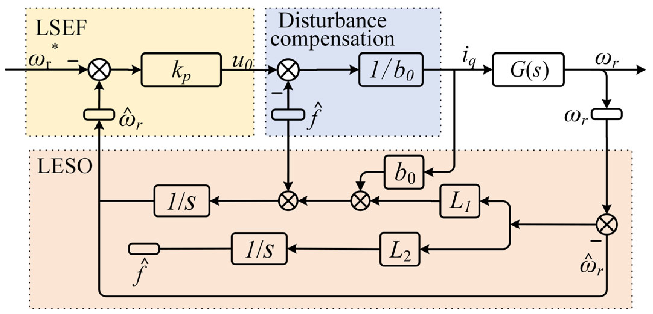
Figure 1 shows the block diagram of the traditional LADRC controller structure. The control process is to use the LESO to estimate the system aggregate disturbance in real-time observation and integrate the aggregate disturbance observation value into the feedback control law to get the final output, so that the LADRC will simplify the complex control system into a simple integral series type control system [
18].
2.2. Study of DLADRC Based on the Principle of Error Control
The principle of deviation control is a basic principle of cybernetics, the essence of which is to use the deviation between the target value and the actual value as the basis for controlling the control object to reduce the deviation between the two. Both proportional integration differentiation (PID) and LADRC use this principle. One of the reasons why LADRC has an advantage over PID is that its LESO can observe disturbance inside and outside the system in real time and compensate the control quantity according to the disturbance. The principle of operation of the traditional LESO is also an application of deviation control theory. The difference is that PID is to make the actual value of the control object follow the given value by controlling the deviation of the output of the given value from the actual value, while LESO is used to control the changes in the observed values to follow the actual values by the deviation between the observed and actual values of the state variables of the system.
According to Equation (4), the observer is regulating the derivatives of z1 and z2 by the error e (t) = z1 − x1, which in turn controls the changes of z1 and z2 so that they track the estimated true values of x1 and x2, respectively. For LESO, it is obvious that making z1 approach x1 quickly is the priority, followed by making z2 approach x2. Once this order is misplaced, the system’s regulation will fail. Of course, the system controls z1 and z2 simultaneously. Under this regulation mechanism, before z1 tracks x1 to the steady state, the control of z2 tracking x2 has little significance, while when the tracking regulation of z1 to x1 is completed, the regulation of z2 becomes difficult because currently, e (t) is already very small. To realize the regulation of z2, the traditional LESO can only be realized by selecting a larger parameter L2. In general, L2 is an order of magnitude larger than L1. Too large a parameter reduces the dynamic performance of the LESO, which cannot be completely solved by selecting a nonlinear function to obtain the characteristics of “small gain, large output, large gain, small output”.
From the above analysis, regulating the derivative of
z1 by
e (
t) in traditional LESO is in accordance with the principle of error control [
23], while regulating the derivative of
z2 by the error
e (
t) is not appropriate. Therefore, this paper uses the deviation of
e (
t) =
z2 −
x2 to regulate the derivative of
z2.
The DLESO is obtained by combining Equation (3) with the above analysis:
where
h1 and
h2 are the gains of the LESO. The same as the traditional LESO, the parameters are configured by the bandwidth method [
29], and the relationship between the observer gains
h1 and
h2 and the observer bandwidth
ω0 is
h1 =
ω0,
h2 =
ω0. The relationship between the feedback law gain
kp and the feedback rate bandwidth
ωc is
kp =
ωc.
In summary, the differential LADRC (DLADRC) controller expression is
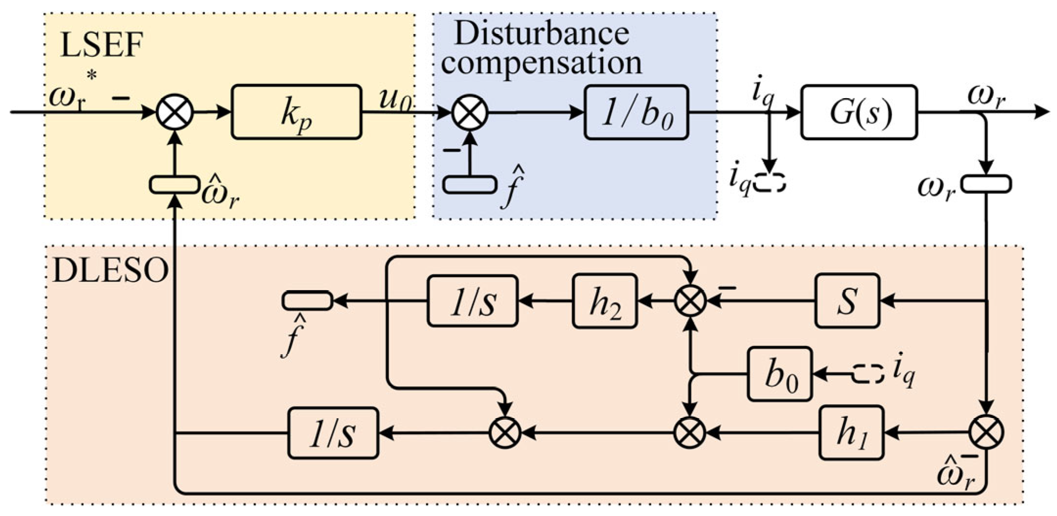
Equation (8) is the PMSM speed control algorithm of DLADRC, and its control system block diagram is shown in
Figure 2.
2.3. Frequency Domain Analysis of DLADRC
The key to DLADRC is that DLESO has the capability of real-time estimation and feed-forward compensation of unknown time-varying perturbations of the system. To analyze its perturbation observation performance, it is necessary to derive the transfer function of the perturbation estimation capability in the frequency domain, i.e., to find the frequency-domain transfer relation between
z2 and
x2. By Laplace transform, the frequency domain expression of
Z2 can be obtained according to Equation (6):
Combining Equations (3) and (9) gives the perturbation estimation capacity transfer function as
From Equation (10), the perturbation estimation transfer function
HD (
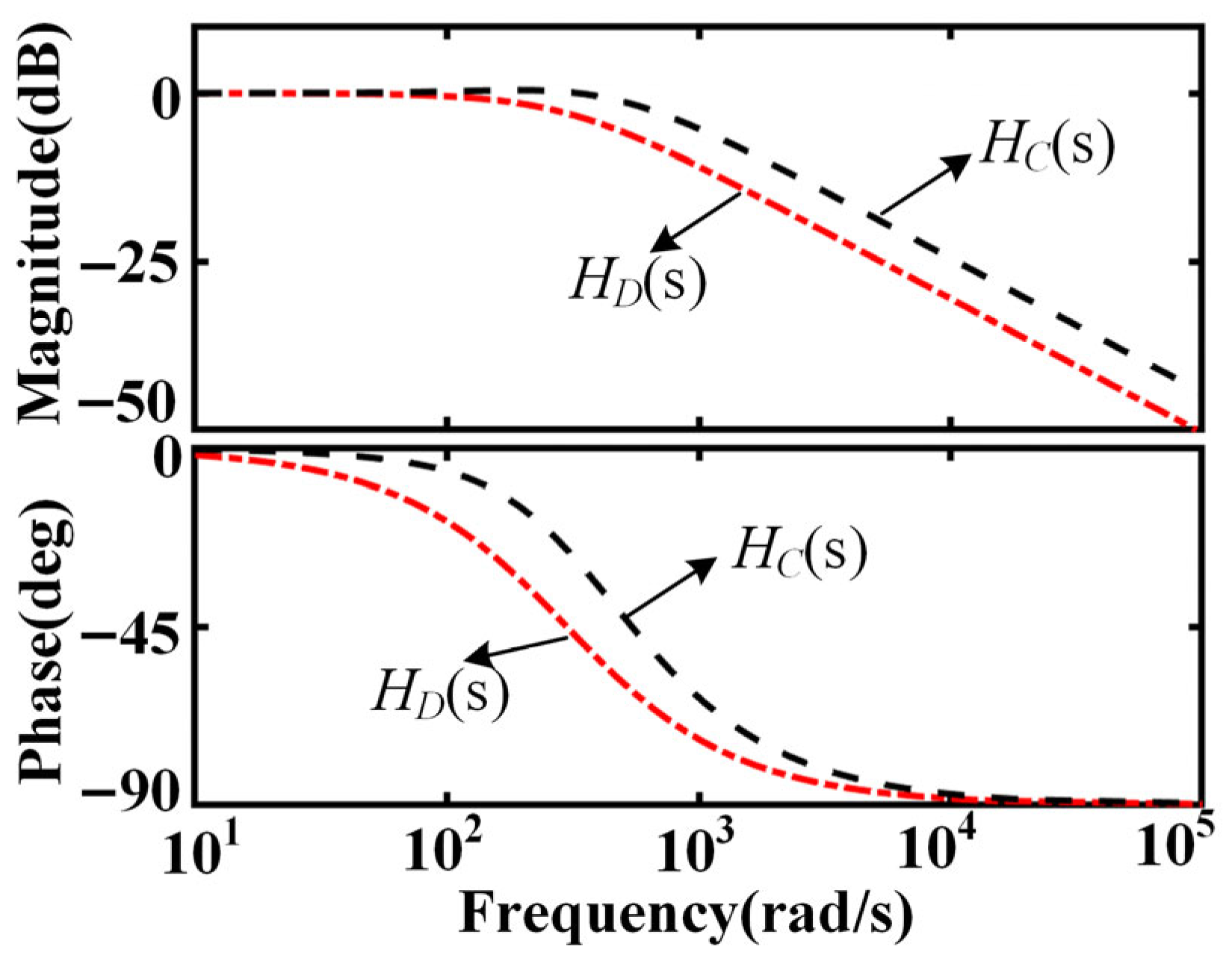
s) is in the form of a standard low-pass filter, and its frequency response is shown in
Figure 3. The results show that the system has a significant phase lag in the mid-frequency band, leading to a time lag in the perturbation observation, which in turn affects the dynamic compensation performance. Increasing the bandwidth can alleviate the phase lag and enhance the perturbation observation performance, but the high bandwidth will amplify the high-frequency noise, which is prone to cause oscillations and reduce the stability of the system.
3. Study of PMSM Speed Controller of STSM-CDLADRC
3.1. Study and Performance Analysis of CDLESO
To solve the above problems, this paper introduces the phase lead correction unit to improve the observer. First, the frequency domain expression of the phase lead correction unit is
where
T is the overcorrection time constant,
ε is the adjustment factor, and
εϵ [0, 1]. The design of reasonable
ε and
T can effectively improve the phase margin of the corresponding frequency band of the system. Specifically, this is obtained by bringing s =
jω into Equation (11):
The phase-frequency characteristic equation
j (
ω) is obtained by taking the partial derivative of
ω and making it equal to 0. The frequency
ωM at the maximum phase shift is obtained as
Bringing Equation (13) into the phase frequency characteristic equation
j (
ω) gives the maximum phase shift
jM as
Connect the phase lead correction unit in series with the disturbance transfer function of the DLESO:
where
Z3 is the Laplace transformed value of the corrected total perturbation observation
z3.
Figure 4 shows the
HC (s) and
HD (s) domain characteristic plots. As can be seen from
Figure 4, compared with DLESO, the system not only improves the phase lag problem after the correction unit but also expands the estimation range of the observer for the total perturbation, improves the observation accuracy of the observer, and further enhances the anti-disturbance performance of the system.
In summary, the expression for the corrected CDLESO is
3.2. Stability Performance Analysis of CDLESO
Let the error
e = [
e1,
e2,
e3]
T, where
e1 =
z1 −
y,
e2 =
z2 −
f,
e3 =
z3 −
z2. The error state equation can be obtained from Equation (14) as
where
η is a finite value of the differential of the total system perturbation
f.
The error state matrix λ is
The characteristic equation of the system can be obtained from the matrix λ:
The table of the corresponding Routh–Hurwitz stability criterion based on the characteristic equations of the system is
The sufficient condition for the Routh–Hurwitz criterion to determine the stability of the system is that all the coefficients of the closed-loop characteristic equation of the system are positive, and the elements of the first column of the Routh–Hurwitz table are positive. It is known that ω0, ε, and T are constants greater than 0. Then the coefficients of the corresponding characteristic equations are all positive, and the elements of the first column of the table are all positive, so it is known that all the characteristic roots of the system lie in the left half of the root plane. Therefore, from the Routh–Hurwitz criterion, CDLESO is asymptotically stable.
3.3. Study of the STSM-LSEF
After the observation estimation of the disturbance by CDLESO and feed-forward compensation of the disturbance, the control system at this time can be equated to an integrator, and the LSEF is like the proportional control of proportional-integral controllers. In the case of the fast dynamic response of the system, if the deviation of the design of the LSEF is too large, it may lead to the generation of the system with overshoots and oscillations, which results in the reduction in the stability and robustness. To solve this problem, the super-twisting sliding mode algorithm is introduced into the LSEF to improve the system stability and robustness by taking advantage of the characteristics of the super-twisting sliding mode’s fast response and its insensitivity to parameter changes and disturbance.
The super-twisting sliding mode algorithm is a second-order sliding mode control algorithm [
30], which adopts the idea of super-twisting control and only needs to know the information of the sliding mode variable s without knowing the value of the first-order derivative of s. In super-twisting sliding mode control, different control modes are used depending on the error value. When the error is small, the controller adopts the traditional sliding mode control; when the error is large, the controller improves the control accuracy by adjusting the super-twisting sliding mode. Compared with the traditional sliding mode control, the super-twisting sliding mode control algorithm uses integrals to obtain the actual control quantity, which has faster response speed and stronger robustness.
For a single-input nonlinear system, the following relationship exists:
where
x is the system state variable,
u is the input variable,
O is the output quantity,
a (
t,
x) and
b (
t,
x) are the unknown continuous sliding mode variable structure functions, and
s (
t,
x) is the unknown sliding mode surface function.
Setting the sliding mode variable
s, the super-twisting sliding mode control algorithm takes the form
where
n1 and
n2 are the parameters to be designed. From the above equation, the super-twisting sliding mode control has two main components. The first component is the nonlinear discontinuous function of the sliding mode variables. The nonlinear variable can be changed by varying the exponent
γ. The second part is the integral value. This causes the second-order sliding mode control to be unaffected by parameter variations, and the system inherent jitter vibration is reduced to enhance the system robustness, where γ is generally taken as
γ = 0.5.
Since the traditional super-twisting sliding mode algorithm uses the sign function, which is discontinuous, it will cause sudden changes in the control input when the system is switched, resulting in the system jittering phenomenon. To minimize the jitter problem of the system, it is considered to replace the sign function sign with a continuous and smooth
sigmoid function, whose expression is
Define the sliding mode surface function of the feedback law error signal as
where
σ1 is the speed tracking error signal, and
σ2 is the derivative of
σ1.
Combining Equations (22)–(24), the improved super-twisting sliding mode control algorithm can be obtained:
Combining Equation (7) yields the STSM-LSEF as
3.4. Stability Analysis of the STSM-LSEF
To analyze the stability of the super-twisting sliding mode LSEF designed in this paper, the following positive definite function is established as the Lyapunov function:
After the sliding mode variable is defined as
s =
z1 −
r according to Equation (26), the following is obtained:
Derivation of Equation (27) is as follows:
Clearly, the following inequality is satisfied for any given s in the sigmoid function:
Therefore, when
n1 and
n2 are both greater than zero, the following is obtained:
From the above analysis, the super-twisting sliding mode LSEF designed in this paper satisfies the Lyapunov stability theory. When n1 and n2 are greater than zero, the system is stable.
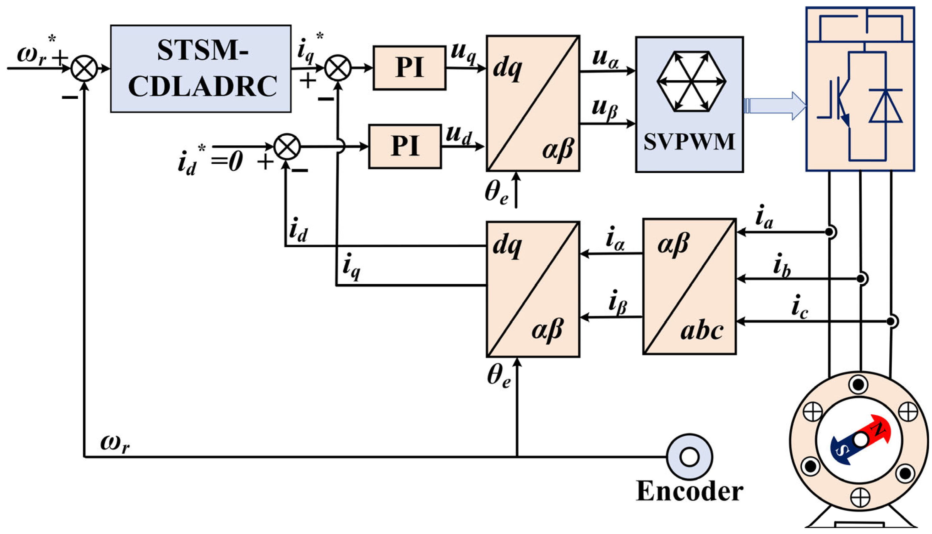
In summary, the control algorithm of STSM-CDLADRC is expressed as Equation (32), and its structure block diagram is shown in
Figure 5.
4. STSM-CDLADRC Controller Parameter Configuration Method
From the above analysis, it can be obtained that the deployment parameters of the controller designed in this paper are system parameters b0, observer bandwidth ω0 (h1 = h2 = ω0), correction parameters ε and T, and control law parameters n1 and n2, and the order of configuration is to first deploy the DLADRC parameters; then, through the frequency domain analysis, determine the system correction parameters; and finally replace the kp (ωc) in the control law with the super-twisting sliding mode algorithm to determine the control law parameters n1 and n2. The specific configuration principles are as follows.
First, the system parameter b0 is deployed: the theoretical value of b0 can be determined from Equation (2) (b0 = 3 npѱf/2 J), and b0 is gradually increased from the theoretical value to ensure that the system is stable enough. In the actual mediation process, b0 cannot be too large; otherwise, it will make the control signal weaker and lead to slower system response. Therefore, a trade-off between stability and response speed is required.
Second, the observer bandwidth
ω0 is deployed: the parameter
ω0 is determined by the single-parameter rectification method [
31], and the observer bandwidth
ω0 is initially determined by the object’s known regulation time
ts based on the bandwidth method. When determining the theoretical value of
ω0, the test is first started from the theoretical value, and then the
ω0 is gradually increased until the influence of the noise is difficult to satisfy the requirements of the system. Next,
ω0 is gradually reduced until the optimal parameter values are obtained to meet the system dynamic requirements for adjustment. The bandwidth ω
c of the control law is determined by the
ω0 = (3–5)
ωc rule.
Then the calibration parameters
ε and
T are deployed: according to steps 1 and 2, after
b0,
ω0, and
ωc are determined, the values of
ε and
T parameters are determined by frequency domain analysis. The theoretical values of
ε and
T are determined by combining Equations (12)–(14) according to the indicators of system steady state error and phase margin [
32]. In the actual parameterization, since the adjustment of
ε affects the gain of the system for high-frequency bands,
ε is adjusted first to ensure that the system is stable enough, and
T is finally adjusted so that the system achieves the expected control effect.
Finally, the control law parameters n1 and n2 are deployed: after determining the above parameters, kp in the control law is replaced by the super-twisting sliding mode algorithm to improve the dynamic response performance of the system. n1 determines the response speed of the system, and the larger n1 is, the faster the system response speed is, but it is too large and leads to overshooting of the system, so the smaller n1 should be selected to satisfy the control performance. n2 determines the steady-state error of the system; in the actual regulation process, the increase in n2 will cause the system jitter amplitude to increase, that is, to meet the requirements of the steady-state error, as far as possible to reduce the value of the n2 parameter.
The above configuration principle is the initial configuration principle; in the actual adjustment process, the system tuning parameter will be coupled with each other and only need to be fine-tuned on the initial value obtained from the above principle.
5. Simulation and Experimental Analysis Results
To verify the feasibility of the STSM-CDLADRC control strategy proposed in this paper, a 5.5 KW PMSM is taken as the control object to build the corresponding double closed-loop vector control model in MATLAB/Simulink 2024a simulation software. The system block diagram of the STSM-CDLADRC control strategy for the PMSM investigated in this paper is shown in
Figure 5. The specific driving parameters of the PMSM system are shown in
Table 1.
For detailed comparative analysis, three control strategies, LADRC, DLADRC, and STSM-CDLADRC proposed in this paper, are selected for the study. The current loop of the three control strategies adopts the PI controller with the same parameters (kp.id = 200, ki.id = 12,000; kp.iq = 600, ki.iq = 8000). The speed loop controller is configured with the same parameters according to the principle of parameter adjustment proposed in this paper, and the parameters b0 = 670, bandwidth ω0 = 530, correction parameter ε = 0.3, T = 0.001, control law parameter n1 = 1500, and n2 = 10 are finally selected after adjustment in this paper.
5.1. No-Load Speed Change Experiment
To test the dynamic response performance of the designed control strategies under variable-speed motion, a speed change experiment is carried out on a PMSM under no-load condition. The simulation time is 1 s. The initial rotational speed of the PMSM system is set to 750 rpm, and the rotational speed is commanded to rise to 1500 rpm in 0.3 s.
Figure 6 shows the rotational speed waveforms of the three control strategies under variable-speed motion. From
Figure 6, the STSM-CDLADRC has stronger stability than the traditional LADRC and DLADRC. The designed STSM-CDLADRC can reach the target speed faster under the sudden change in operating speed and has faster dynamic response capability.
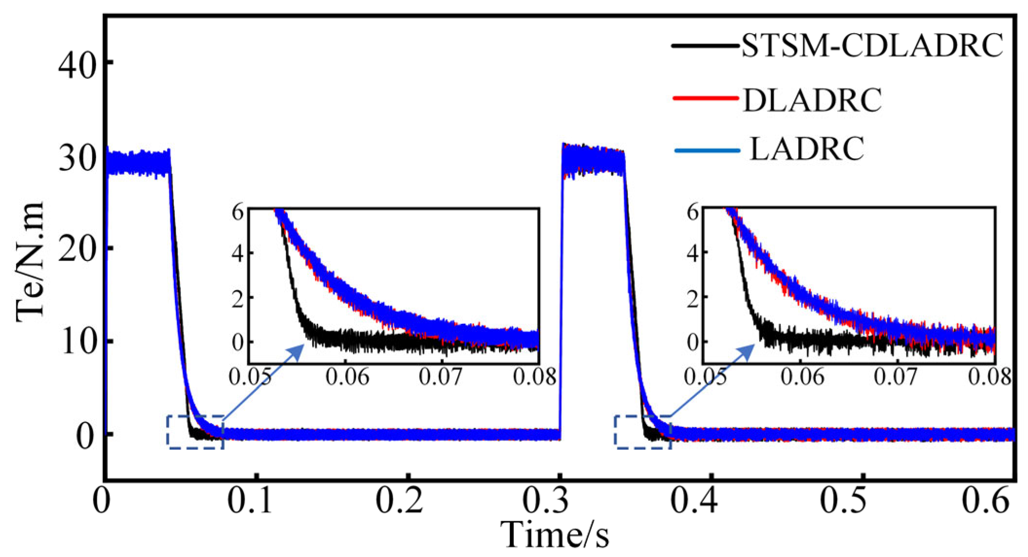
The no-load electromagnetic torque waveforms of the three control strategies in the case of variable-speed motion are shown in
Figure 7. Through
Figure 7, the STSM-CDLADRC designed in this paper can be adjusted more quickly than the other two control strategies in the case of a sudden change in speed, with a smaller adjustment time and a faster dynamic response speed. The simulation analysis of the PMSM system under variable-speed motion in
Figure 6 and
Figure 7 proves that the STSM-CDLADRC proposed in this paper has superior dynamic response performance and control performance.
5.2. Sudden Change Load Experiment
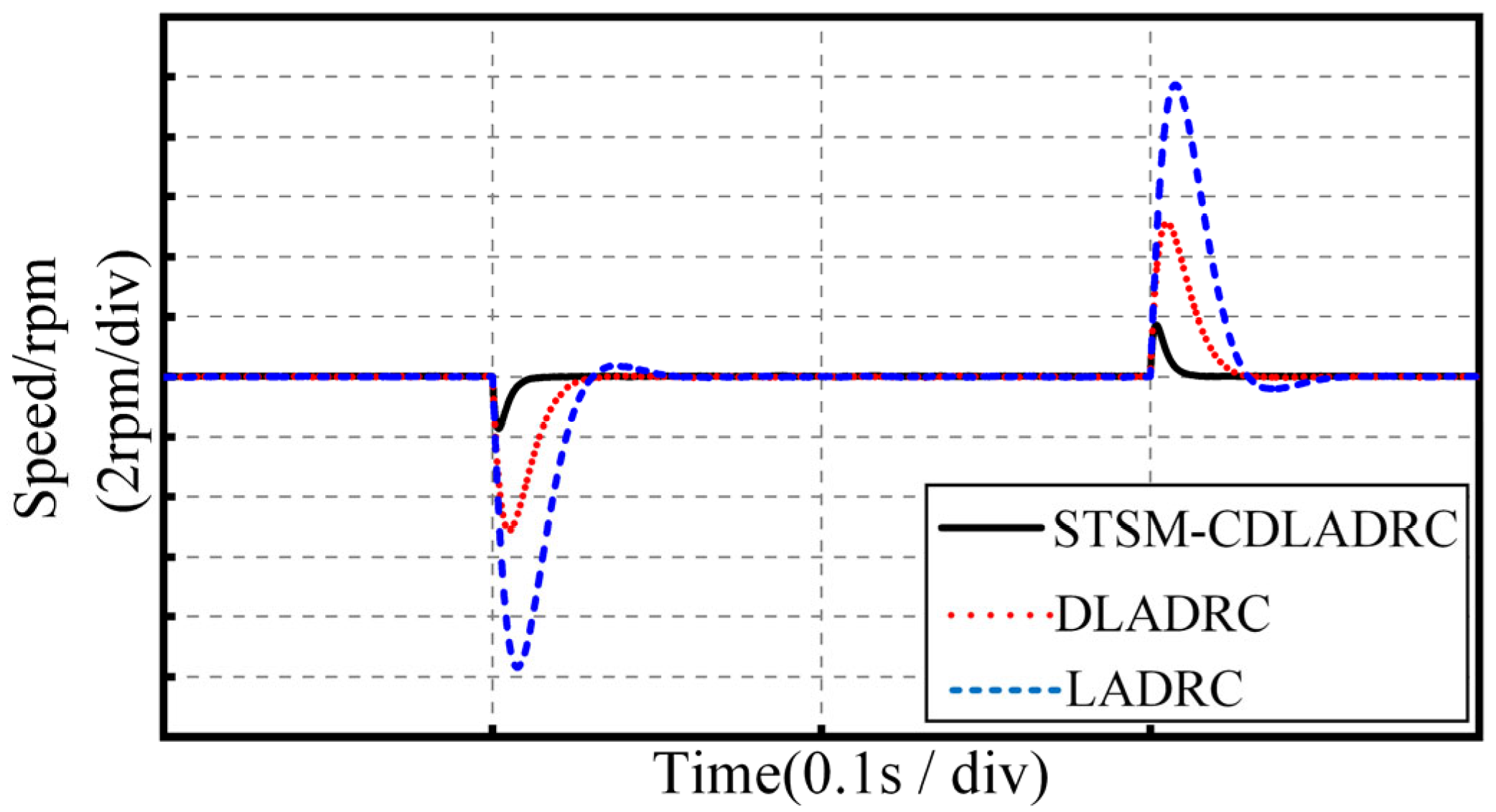
To test the anti-disturbance ability of the three control strategies in the PMSM system under sudden load change, the PMSM is subjected to sudden load change experiments at a given operating speed of 1500 rpm. With the motor operating stably at the rated speed of 1500 rpm, a sudden load was applied at 0.3 s and suddenly removed at 0.5 s.
Figure 8 shows the speed waveforms of the three control strategies in the case of sudden load addition and removal in the system. From the figure, after 0.3 s sudden load addition of 10 N m, the three control strategies of STSM-CDLADRC, DLADRC, and LADRC have speed disturbances of 2 rpm, 6 rpm, and 12 rpm, respectively, and the adjustment time required for the three control strategies to be adjusted to a stable state is 0.02 s, 0.045 s, and 0.055 s, respectively. After sudden load removal, the speed disturbances of STSM-CDLADRC, DLADRC, and LADRC are 1.9 rpm, 5.8 rpm, and 11.8 rpm, respectively, and the regulation times required for the three control strategies to be adjusted to a steady state are 0.02 s, 0.04 s, and 0.05 s, respectively.
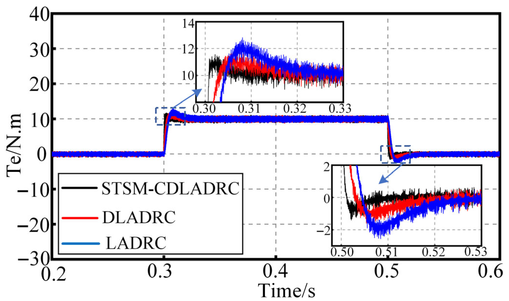
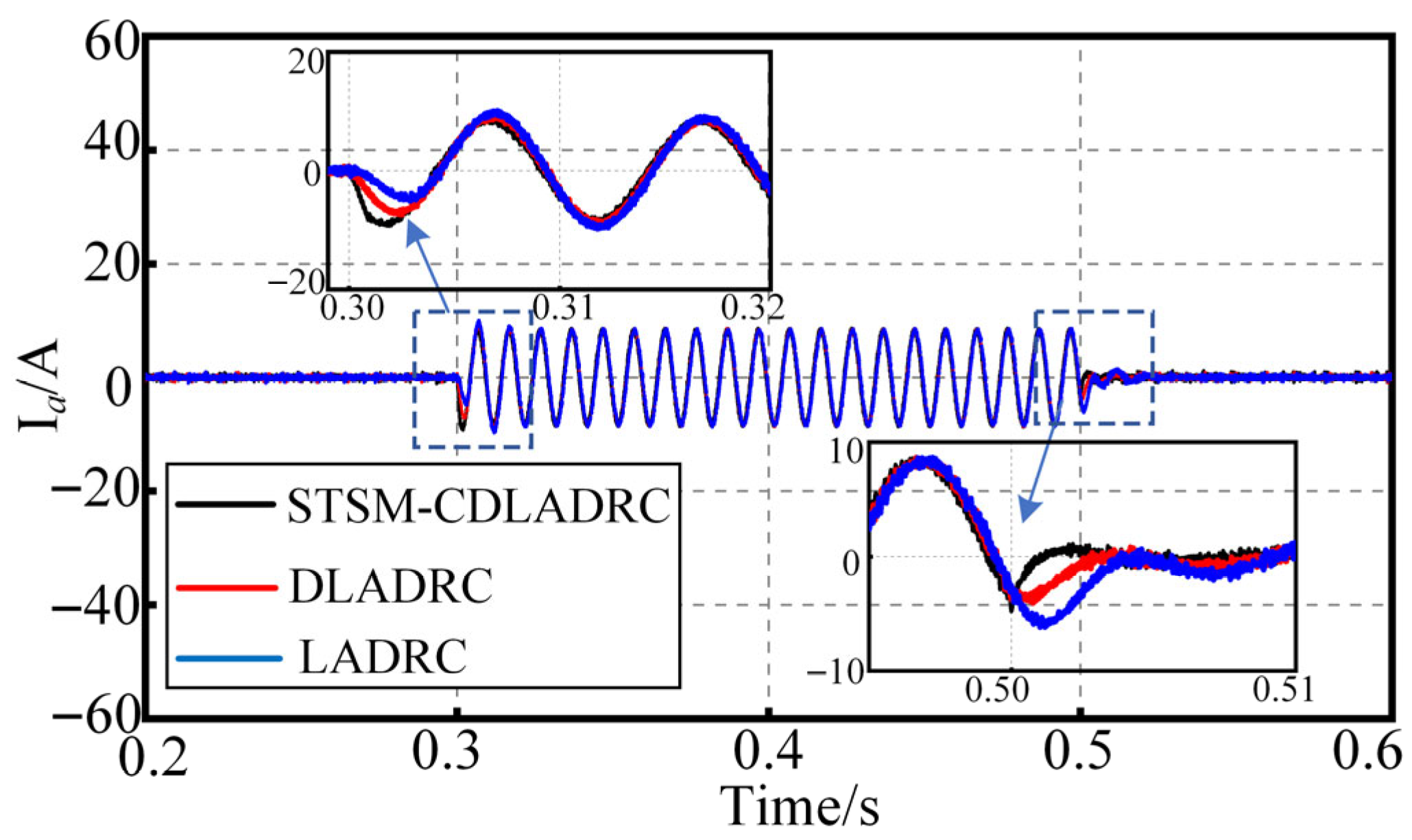
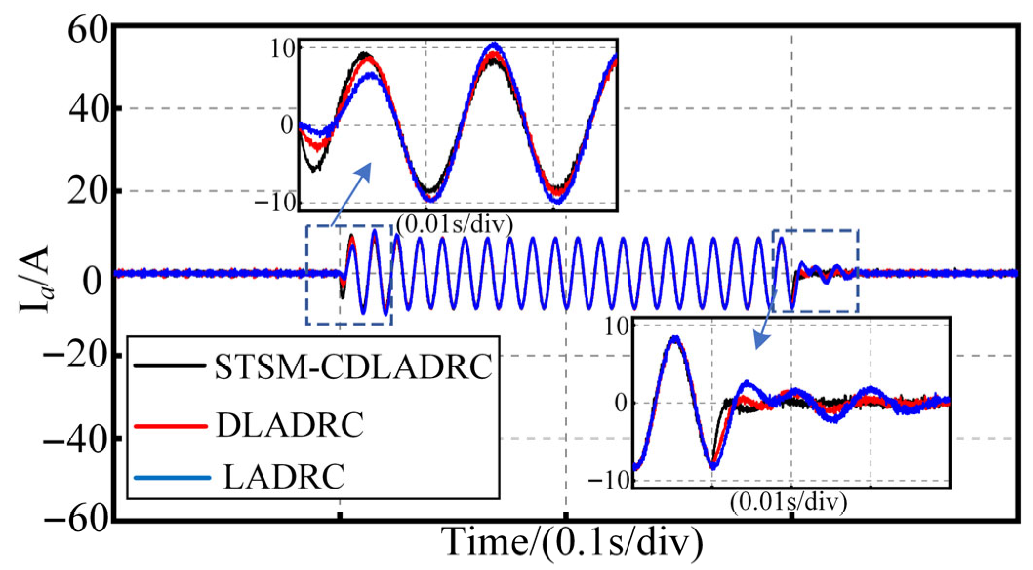
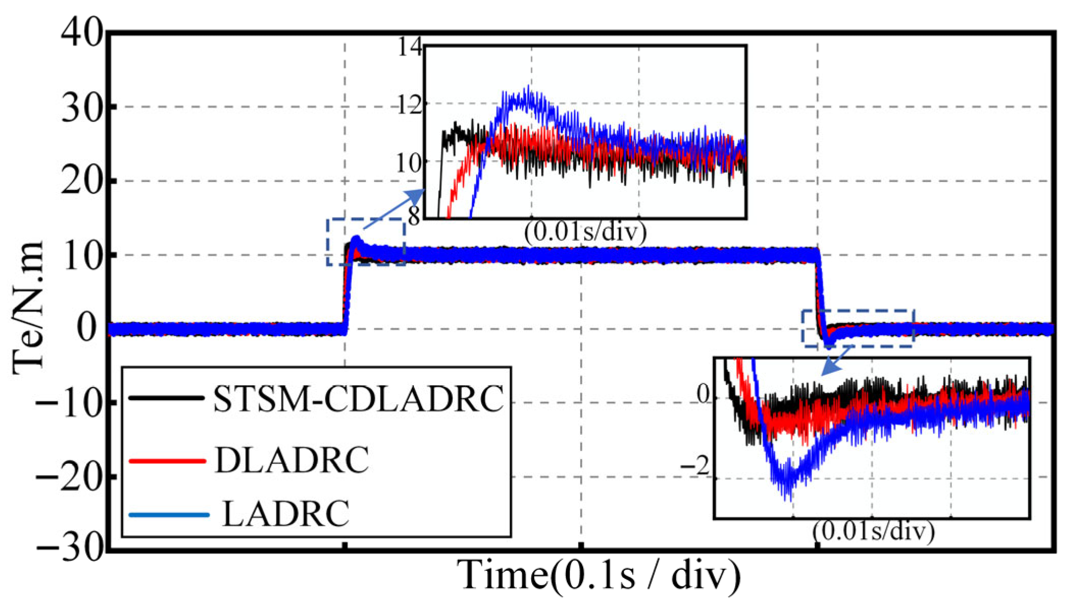
The waveforms of torque and current
Ia are shown in
Figure 9 and
Figure 10, respectively, for the three control strategies in the case of sudden load addition and removal of the system. From
Figure 9 and
Figure 10 compared with LADRC and DLADRC, the STSM-CDLADRC studied in this paper has smaller disturbance and faster regulation speeds for both electromagnetic torque and current
Ia in the case of sudden loading and unloading. Through the above analyses, the STSM-CDLADRC in this paper has smaller disturbance and shorter regulation time than the other two control strategies, which reflects that the STSM-CDLADRC has strong perturbation resistance and control performance.
5.3. Parameter Mismatch Experiment
Figure 11,
Figure 12 and
Figure 13 show the waveforms of speed, torque, and A-phase current
Ia of the motor at rated speed under sudden load addition and unloading condition when the parameter of rotational inertia J is mismatched and increased to 2 J, respectively. As can be seen from
Figure 11, when the inertia parameter J is increased to 2 J, the speed perturbation of the three control strategies STSM-CDLADRC, DLADRC, and LADRC after the sudden addition of a 10 N m load are 1.7 rpm, 5 rpm, and 9.8 rpm, respectively, and the adjustment times required for the three control strategies to adjust to the steady state are 0.02 s, 0.04 s, and 0.06 s. In the case of the sudden unloading of the motor at the rated speed, the speeds of the three control strategies are 0.02 s, 0.04 s, and 0.06 s, respectively. Under the sudden load unloading condition, the speed perturbations of the three control strategies are 1.7 rpm, 5.1 rpm, and 9.8 rpm, and the regulation times required for the three control strategies to be adjusted to the steady state are 0.016 s, 0.034 s, and 0.08 s. From
Figure 12 and
Figure 13, when the inertia parameter
J is increased to 2
J, the STSM-CDLADRC has lower perturbation of electromagnetic torque
Te and A-phase current
Ia and shorter regulation time compared with the DLADRC and LADRC under the sudden change load condition.
Figure 14,
Figure 15 and
Figure 16 show the waveforms of speed, torque, and A-phase current I
a of the motor under sudden load addition and unloading condition when the mismatch of rotational moment of the inertia J parameter is reduced to 0.5 J, respectively. As can be seen from
Figure 14, when the inertia parameter J is reduced to 0.5 J, the speed perturbation of STSM-CDLADRC is reduced by 1.6 rpm and 10 rpm, and the regulation time is reduced by 0.01 s and 0.04 s, compared with those of DLADRC and LADRC, respectively, in the sudden load addition condition; in the sudden load removal condition, the speed perturbation is reduced by 4.2 rpm and 12.6 rpm, and the regulation time is reduced by 0.02 s and 0.03 s.
From
Figure 15 and
Figure 16, when the inertia parameter J mismatch is reduced to 0.5 J, the electromagnetic torque
Te and the A-phase current
Ia of the STSM-CDLADRC under the sudden load change condition have a smaller amount of perturbation and a faster regulation speed.
In summary, STSM-CDLADRC exhibits stronger parameter robustness under inertial parameter mismatch and significantly outperforms DLADRC and LADRC control strategies.
5.4. Analysis of Experimental Results
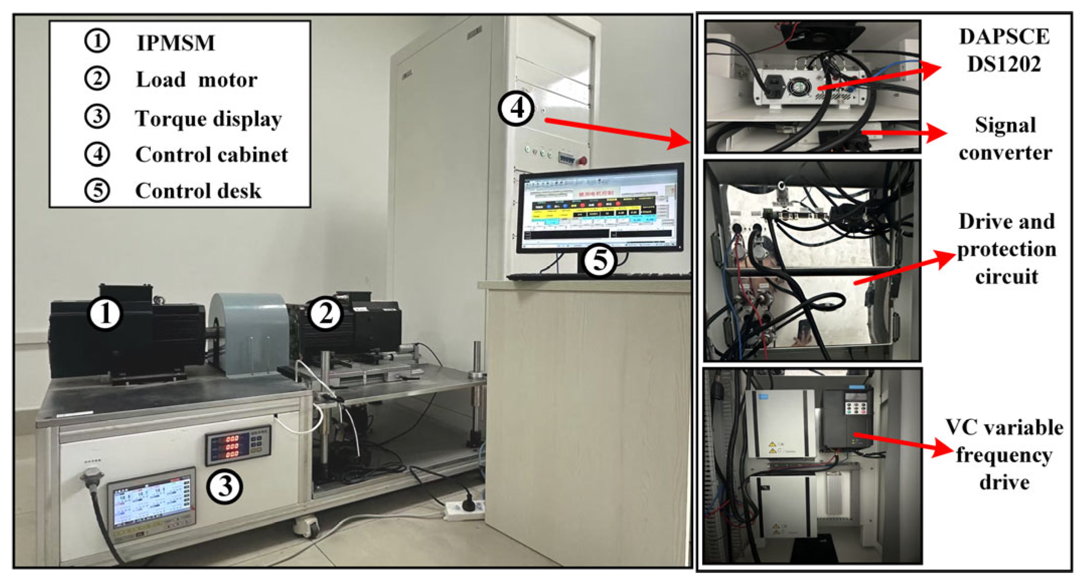
Based on the simulation analysis, load step experiments were further conducted on a DSPACE semi-physical platform to verify the feasibility and effectiveness of the proposed STSM-CDLADRC. The platform consists of a PMSM, a load motor, a control cabinet, and a host computer. The control cabinet integrates a DSPACE DS1202, an inverter, and drive circuits, while the host computer is used for waveform display and data storage. A photograph of the experimental platform is shown in
Figure 17. The motor parameters employed in the experimental platform are consistent with those used in the simulation analysis, thereby ensuring a reliable comparison between simulation and experimental results. In the experiments, the motor speed was set to the rated value of 1500 rpm with a data acquisition period of 6 s. The motor speed and electromagnetic torque responses under variable load conditions were comparatively analyzed.
Figure 18 shows the experimental waveforms of the speed of the three control strategies in the case of sudden loading and unloading of the system. From the figure after the sudden addition of 10 N m load, the three control strategies of STSM-CDLADRC, DLADRC, and LADRC have speed perturbations of 22 rpm, 31 rpm, and 43 rpm, respectively, and the adjustment times required for the three control strategies to adjust to the stable state are 0.8 s, 1.2 s, and 1.4 s, respectively. After the sudden removal of the load, for CDLADRC, DLADRC, and LADRC, the speed perturbations of the three control strategies are 20 rpm, 30 rpm, and 41 rpm, respectively, and the adjustment times required to adjust the three control strategies to the steady state are 0.75 s, 0.85 s, and 1.2 s. The results show that the STSM-CDLADRC in this paper has a faster response speed and a smaller amount of disturbance than the other two control strategies, and the regulation time is shorter, which reflects that the STSM-CDLADRC has a strong anti-disturbance performance and control performance.
Figure 19 shows the experimental waveforms of the torque of the three control strategies in the case of sudden loading and unloading of the system. From
Figure 19, the electromagnetic torque of the STSM-CDLADRC designed in this paper can be quickly restored to a stable state when the load is changed, and the electromagnetic torque of the STSM-CDLADRC studied in this paper has a smaller amount of perturbation and a faster regulation speed under sudden load and unloading conditions compared with the LADRC and the DLADRC.
Based on the above analysis, under variable-load conditions, the proposed STSM-CDLADRC exhibits smaller speed and torque fluctuations and shorter settling times compared with the other two control strategies. The experimental results are highly consistent with the simulation outcomes in terms of overall trends and control performance, fully demonstrating that STSM-CDLADRC achieves fast dynamic response and strong disturbance rejection capability.
6. Conclusions
To improve the dynamic response performance and anti-disturbance performance in PMSM speed control system, this paper designs a super-twisting sliding mode based corrected differential linear active disturbance rejection control strategy for permanent magnet synchronous motor speed control (STSM-CDLADRC). The specific conclusions are as follows:
In the theoretical analysis, regarding the control law, the STSM algorithm is incorporated into the LSEF by leveraging its characteristics of fast response and insensitivity to parameter variations and disturbances, thereby further enhancing the dynamic response capability of the system. In terms of observer optimization, frequency-domain analysis shows that with the introduction of a correction unit, the CDLESO not only improves the phase lag problem but also expands the estimation range of the total disturbance compared with the DLESO, thus improving the observation accuracy of the observer and further strengthening the system’s disturbance rejection capability.
In the simulation validation, the proposed STSM-CDLADRC achieves faster dynamic response in variable-speed experiments and smaller disturbance and shorter settling times in variable-load and parameter-mismatch experiments. In the experimental validation, under sudden load conditions, the speed drop of STSM-CDLADRC is reduced by 9 rpm and 21 rpm compared with LADRC and DLADRC, respectively, while the settling time is shortened by 0.4 s and 0.6 s. Moreover, after load changes, the electromagnetic torque can quickly recover to a stable state, fully demonstrating the superior robustness of the proposed control strategy.
In summary, under various operating conditions, the proposed STSM-CDLADRC demonstrates smaller speed and torque fluctuations, as well as shorter settling times, compared with LADRC and DLADRC, indicating faster response and stronger disturbance rejection capability. These results are consistent with the theoretical analysis: the incorporation of STSM-LSEF significantly enhances the system’s dynamic response, while the design of CDLESO improves the observer accuracy and overall robustness. The combination of these two elements leads to superior overall controller performance, thereby validating the effectiveness and rationality of the proposed method. The present study still has several limitations: it has been validated only over a limited range of tested operating points, and the long-term stability and durability of the proposed control strategy have not been assessed, which will be addressed in future work.
