1. Introduction
Buoyancy-assisted flow and thermal transport in an enclosed finite-shaped space with differently heated side walls and adiabatic horizontal boundaries has been a classical geometry investigated for several decades due to its relevance in many important industrial applications. In particular, an upright annular geometry constructed by two co-axial cylinders has many potential applications, such as nuclear reactors, dry-type transformers, and cryogenic engines. Further, to cater to the high demands of modern cooling equipment, for enhanced thermal transport, the traditional fluids are replaced by nanofluids (NF), a combination of different nanoparticles (NP) and a choice of base fluids (BF) [
1]. Nanofluids, representing an innovative and alternative heat transfer fluid, have garnered considerable research interest due to their enhanced thermophysical properties that enable exceptional performance across diverse engineering applications. Researchers have thoroughly investigated and reported that the incorporation of NPs profoundly modifies thermal conductivity, viscosity, and enhances the overall heat transfer efficiency of conventional base fluids, documenting substantial performance enhancements in various thermal systems [
2,
3,
4]. Hybrid nanofluids (HNFs) comprise carefully engineered combinations of two different NP dispersed in base fluids, demonstrating superior thermal characteristics as compared with conventional single-particle nanofluids [
5,
6].
Buoyant as well as conjugate convection of NF in an annular domain with partial heating and cooling has been investigated in detail, examining various BFs and NP combinations. These studies also proposed thermal rate correlations and identified optimal positions for source–sink combinations to enhance thermal transport rates [
7,
8,
9]. By adopting a combined numerical and artificial neural network approach, Shilpa et al. [
10] analyzed magentothermosolutal convection in a tilted annular space by considering magnetic force and radiation impacts. Kanimozhi et al. [
11] reported the multicellular thermocapillary convective flow structure in nanofluid-saturated porous annular geometry due to a non-uniform sinusoidal thermal profile along the cylindrical surfaces. Swamy et al. [
12] analyzed conjugate magnetohydrodynamic heat transfer in an HNF-filled annular space, and their findings revealed that an optimized heat transfer occurred with minimum wall thickness, maximum thermal conductivity ratio, equal proportions of MWCNT and Ag nanoparticles, and uniform heating. Keerthi et al. [
13] made an attempt to study the impacts of physical and geometrical parameters on NF flow and thermal dissipative mechanisms in an inclined porous annular domain and reported that the inclination angle is a crucial parameter in altering the thermal dissipation rate. Benkherbache et al. [
14] examined BDC within an HNF-filled annular cavity under MF influence by considering four different NP combinations and fin variations. They reported that optimizing the interplay between NPs, the number of fins, and MF strength is crucial to enhancing the thermal efficiency in annular systems. Foukhari et al. [
15] examined MHD thermal transport and entropy production in an HNF-filled annular space with a partially packed porous structure, and they predicted that enhancement in the Rayleigh number and NP concentration increases thermal transport, while the entropy production showed varying responses to changes in different parameter regimes. Magnetothermo-convection of Casson fluid in the annular geometry between two co-axial tubes under the influence of porosity and thermal radiation identified the situations to minimize the entropy production for efficient energy utilization in non-Newtonian fluid flow applications [
16]. Recently, buoyant-assisted convective cooling in an open-ended cylindrical annulus with discrete heat sources reveals that the radius ratio is the most influential parameter rather than the thermal source dimension and position [
17]. Acharya [
18] examined the impacts of curved fins on entropy and hydrothermal behavior of buoyancy-driven MWCNT-Fe
3O
4-H
2O HNF within an annular enclosure, and reported that curved fins maximized heat transport by
and significantly reduced system irreversibility as compared with the no-fin case. A detailed investigation of buoyancy-assisted thermal transport in different annular geometries with various NFs and constraints has been reported and discussed in [
19]. It is worth mentioning that the above-stated investigations in an annular domain mainly focus on the NF (or traditional fluid) flow and thermal transport processes having a partially heated segment with or without a porous medium, but they do not focus on the inclined magnetic force.
Extensive theoretical analyses and laboratory experiments were conducted on buoyancy-assisted fluid flow and thermal transport processes within square and rectangular conduits by employing a diverse range of working fluids. These geometrical configurations portray a wide range of applications, including heat exchangers, electronic cooling systems, HVAC equipment, and solar thermal collectors. Tayebi and Chamkha [
20] numerically analyzed buoyancy-assisted convection in a hybrid nanofluid-filled square conduit with a sinusoidally hot wall, and reported that hybrid NF consistently outperformed conventional NF. In their analysis, Loenko et al. [
21] examined conjugate thermo-gravitational convection of non-Newtonian fluids inside a square conduit with a thermal source, and addressed the critical need for advanced cooling solutions in microelectronics and power engineering applications to enhance system performance and reliability. Samadder and Ray [
22] examined buoyancy-driven convection and entropy production in a hybrid NF-filled corrugated geometry with discrete heaters. Their study revealed that increasing the heater aspect ratio decreased both thermal transport and entropy production, and reported optimal cooling parameters. More recently, An et al. [
23] applied LB technique to study the various impact of thermal source on BDC in a square as well as cubic geometries and proposed novel strategies about the thermal source distributions for specific industrial and practical needs. The impacts of porosity and periodic MF on BDC in square domains containing diverse NFs could be found in the recent investigations [
24,
25,
26].
Numerous computational and experimental investigations were conducted on magnetohydrodynamic (MHD) buoyancy-driven convection of NFs across diverse geometric configurations. Though the pioneering study of MHD was developed for addressing astrophysical and geophysical challenges, a substantial amount of research was focused on leveraging magnetic fields as an effective mechanism to regulate convective NF flow and heat transfer characteristics in different geometries [
27,
28]. In a hybrid NF-filled square conduit, Reddy and Sreedevi [
29] investigated entropy production and thermal transport under the influence of uniform MF and thermal radiation. Munawar et al. [
30] investigated mixed convection in a HNF-filled squared geometry with a circular thermal source under the influence of an oblique MF, and reported recommendations for heat transfer optimization. The positional influences of discrete heaters and coolers on buoyant thermal processes have been investigated by Chatterjee et al. [
31] in a cylindrical thermal setup containing hybrid nanofluid under magnetic force influence. Their predictions determined that diagonally positioned heater–cooler arrangements yield the optimal thermal performance. Magneto-convective motions and thermal transport improvement in a HNF-filled square porous conduits with isolated heating–cooling can also be optimized by utilizing different nanoparticle shapes [
32]. Rahaman et al. [
33] examined the heater positional effects on MHD convection in a NF-filled grooved channel under an inclined MF by considering six heater configurations, and identified optimal positioning of heater and MF orientation to achieve improved thermal transport.
The advantage of choosing an oblique MF as compared with a constant MF lies in its ability to provide more accurate control over convective flow patterns and thermal transport rates. The oblique MF generates asymmetric Lorentz forces that could selectively suppress or enhance the fluid movements in particular directions. Furthermore, the orientation of MF admits the design engineers to optimize the thermal performance for specific applications by adjusting the MF angle rather than its strength [
34,
35,
36]. By considering dual thermal source–sink combinations and an oblique magnetic force, Ameer [
37] analyzed the thermodynamic performance of buoyancy-assisted convective thermal transport in a porous-square geometry with two different hybrid nanofluids. Their predictions reveal a particular combination of NP leads to maximizing the thermal transport with minimized entropy production, and the presence of a magnetic force delays the thermal transport rates. The synergistic interaction between MHD forces and porosity characteristics within different bounded domains saturated with NF or HNF subjected to non-uniform thermal conditions has also garnered considerable attention [
38,
39,
40]. The strategic placement of isolated thermal segments on the boundaries of complex geometries offers enhanced control over convective patterns as well as thermal distributions, in particular, optimizing thermal management strategies for specialized engineering solutions [
41,
42,
43,
44].
A comprehensive review of literature examining NF-based heat transfer in discretely heated–cooled geometries reveals a critical research gap in the field, particularly with the geometrical impacts on flow dynamics. Though extensive studies exist on mono and hybrid NP-filled configurations, the specific domain of buoyancy-driven convection (BDC) in an annular geometry with discrete heating and cooling zones remains underexplored. This gap is particularly evident in the context of integrating advanced machine learning approaches with traditional computational fluid dynamics. The industrial significance of annular domain, coupled with the enhanced thermal performance potential of HNFs, makes this knowledge gap particularly noteworthy. This novel integration offers a more nuanced understanding of heat transfer phenomena in a discretely heated–cooled annular system containing hybrid NFs. The current analysis is organized as follows: The problem formulation and numerical approach, including validation studies, are, respectively, structured in
Section 2 and
Section 3, followed by the machine learning methodology in
Section 4. Results and discussions are detailed in
Section 5. Finally, the conclusions are presented in
Section 6.
2. Mathematical Formulation and Model Equations
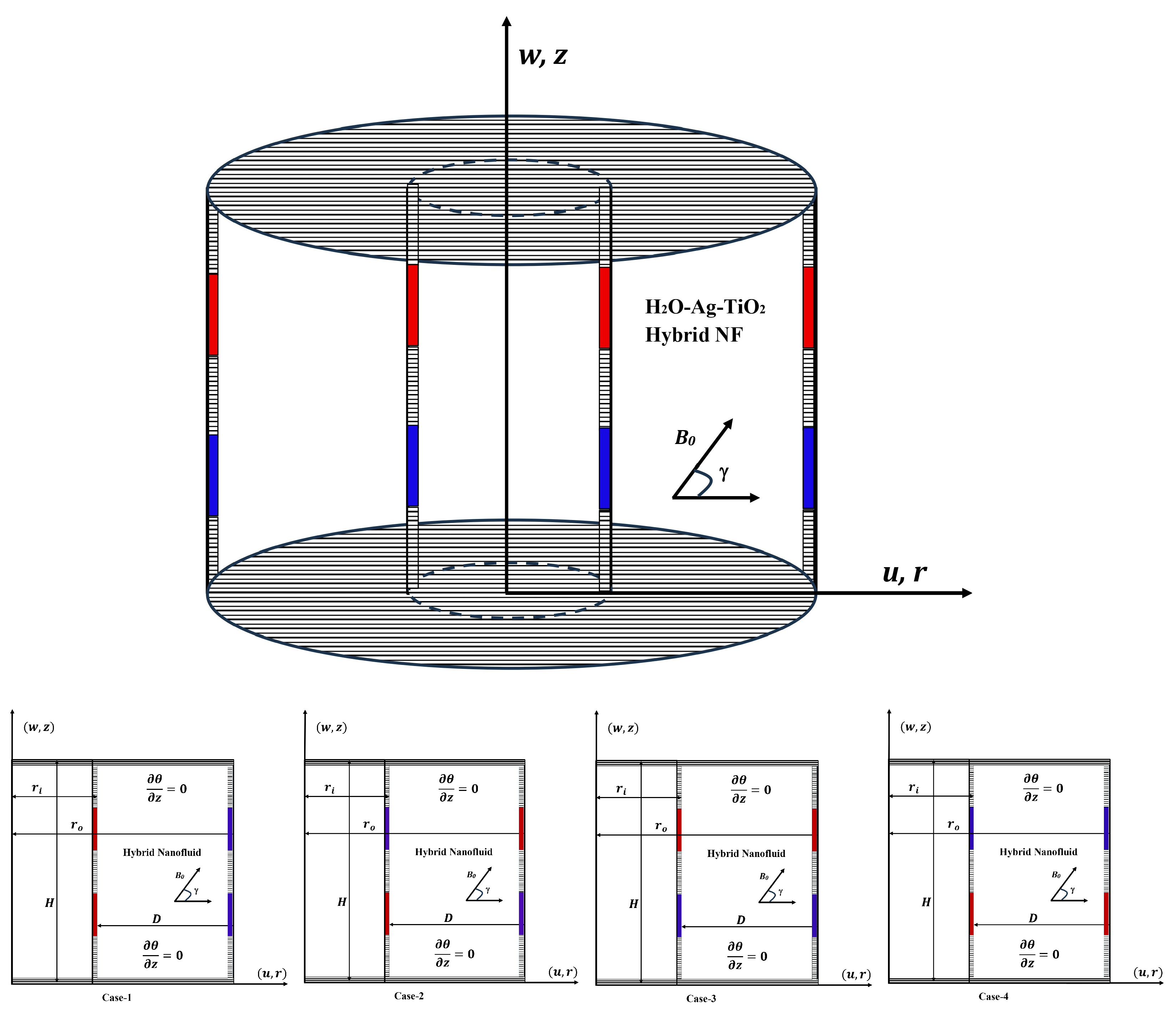
This analysis investigates buoyant-assisted flow and thermal behavior within an upright annular geometry formed by two co-axial cylindrical tubes as depicted in
Figure 1. The annular space, characterized by a width
D and height
H, is bounded by inner and outer cylindrical walls of radii
and
, respectively. The inner and outer cylindrical surfaces are placed with thermal sources (red segment with higher thermal conditions) and sinks (blue segment having lower thermal conditions) and placed at different locations. The dimensions (lengths) of sources/sinks are fixed at
and their bottom and top locations along the inner and outer cylinders are, respectively, fixed at
and
units from the bottom surfaces. In particular, we examine four distinct thermal boundary configurations:
Side heating–side cooling (Case-1): Here, the sources and sinks are, respectively, placed along interior and exterior cylinders.
Cross heating–cross cooling (Case-2): Placing a thermal source at the bottom position of the inner cylinder and another source at the upper location of the outer cylinder, thus creating diagonal thermal gradients;
Upper heating–lower cooling (Case-3): Here, the sources and sinks are, respectively, placed at the upper and lower portions of the interior and exterior cylinders;
Upper cooling–lower heating (Case-4): The sinks and sources are placed, respectively, at upper and lower locations of inner and outer cylinders.
Further, the top and bottom boundaries of the annular space remain thermally insulated throughout all cases. The enclosure contains a water-based hybrid nanofluid, specifically H
2O carrying a suspension of both silver (Ag) and titanium dioxide (TiO
2) NPs. Although the current model works for any combination of NPs, the selection of Ag + TiO
2 hybrid nanofluid was based on their complementary properties. Ag provides high thermal conductivity, while TiO
2 might help with stability, and the combination might provide better dispersion stability. Combining the antimicrobial properties of Ag with the photocatalytic properties of TiO
2 would extend the operational life and maintain the efficiency of the thermal systems.
Table 1 documents the required thermophysical characteristics of these constituent materials. Our analysis incorporates an external magnetic field (MF) of uniform strength B
0, applied at various inclination angles
measured relative to the
r-axis. The theoretical models used to calculate effective properties of the hybrid nanofluid mixture are presented in
Table 2, accounting for the complex interactions between the base fluid and dual NP types. The models presented in
Table 2 were chosen based on their demonstrated accuracy across diverse theoretical analysis and their widespread adoption in HNF research. Furthermore, we consider five distinct NP shapes in our parametric investigation, with the corresponding shape factors and relevant parameters detailed in
Table 3. This comprehensive approach allows us to examine the combined effects of MF orientation, thermal boundary configurations, and nanoparticle morphology on heat transfer performance. In addition, we model the working medium as a Newtonian fluid, with the flow characteristics considered time-dependent (unsteady); however, maintaining axial symmetry and laminar behavior. In our mathematical formulation, to account for buoyancy effects while simplifying the governing equations, we implement the Boussinesq approximation, which treats density as constant except in the body force terms.
2.1. Governing Model Equations
Using the above foundational assumptions within the magnetized hybrid nanofluid system, the complex buoyancy-assisted flow and heat transfer phenomena is characterized by the following mathematical expressions [
12,
13].
To facilitate further mathematical analysis, the pressure gradient terms
have been eliminated from the axial and radial momentum equations as detailed in [
12,
13]. For this, we introduced the stream function
and reformulated the governing equations in terms of vorticity
. The resulting dimensionless vorticity-stream function form of the transformed equations can be expressed as:
where
The following dimensionless transformations are utilized to recast the above set of equations:
In the above table, the parameter
m is known as the shape factor for different-shaped NPs that assumes different values and is based on the shape of the NP. The magnitudes of
m for different shaped NPs are given in
Table 3.
2.2. Boundary Conditions
The auxiliary conditions for the governing model are given as follows. Initially, it has been assumed that the fluid is motionless and has a uniform temperature. This indicates
. The hydrodynamic and thermal boundary conditions utilized in the present analysis are provided in
Table 4.
2.3. Thermal Transport Rate
In thermal transport phenomena analysis, the principal quantitative parameter of interest for all practical engineering applications is the global thermal transport rate across the thermal boundaries. This quantity, characterized by the average Nusselt number, serves as a critical metric for evaluating thermal exchange efficiency between thermal sources and the adjacent hybrid NF. The
effectively quantifies the ratio of convective to conductive thermal transfer and provides fundamental insight into the enhancement of thermal transport mechanisms. For comprehensive thermal analysis, this essential parameter is mathematically estimated as follows:
In the above equation, , are the dimensionless location of thermal sources, placed on either cylinders, and are measured as the distance between the middle of the source and the lower boundary. Also, is the dimensionless length of the source, which is kept fixed at throughout the analysis.
4. Artificial Neural Network (ANN) Performance Analysis
In the present investigation, the incorporation of an artificial neural network (ANN) framework serves two critical roles. Primarily, it offers an efficient, data-driven alternative to the computationally intensive finite difference simulations, thereby substantially reducing the time and resources required to estimate the average Nusselt number under varying physical conditions. This predictive capability becomes particularly valuable in scenarios involving extensive parametric analysis, online control systems, or multi-criteria optimization—contexts where repeated high-fidelity simulations are impractical due to their prohibitive computational demand. Additionally, the ANN architecture is adept at capturing intricate, nonlinear interdependencies among key governing parameters such as the Rayleigh number (Ra), Hartmann number (Ha), magnetic field inclination (), nanoparticle concentration (), and the imposed thermal boundary regimes. These multidimensional interactions, often convoluted in their physical coupling, pose significant analytical and numerical challenges. By leveraging the ANN’s learning capability from representative simulation data, the model furnishes a resilient and scalable surrogate that approximates thermal transport behavior with notable precision, while maintaining computational efficiency suitable for real-time or iterative use.
Although computational fluid dynamics (CFD) offers highly resolved, physics-based predictions rooted in the fundamental laws of thermofluid science, its application becomes computationally prohibitive in scenarios demanding extensive parametric exploration, real-time control feedback, or iterative optimization cycles. To circumvent this limitation, the present work employs an artificial neural network (ANN) model trained on data obtained from rigorously validated CFD simulations. This strategic integration enables the ANN to internalize the essential physical relationships embedded in the numerical results, while furnishing instantaneous estimations of thermal performance indicators such as the average Nusselt number. In doing so, the ANN effectively bridges the gap between high-fidelity simulation and computational tractability—supporting rapid, large-scale evaluations across diverse operational regimes. The hybrid CFD–ANN paradigm thus capitalizes on the complementary strengths of deterministic modeling and data-driven inference, yielding a versatile and efficient surrogate modeling approach tailored for advanced thermal system analysis.
The dataset employed for training the ANN model was curated from a suite of high-fidelity finite difference simulations that explored a broad spectrum of thermophysical and geometrical parameters central to hybrid nanofluid convection. The input feature space was defined by four key dimensionless groups: the Rayleigh number (Ra), Hartmann number (Ha), Magnetic field angle (), and NP concentration (). These parameters were systematically varied within rigorously selected bounds informed by authoritative literature to ensure physical relevance and practical applicability. The simulation outputs were compiled into structured Excel sheets and subjected to random shuffling via MATLAB (Version: 2025) randperm utility, thereby eliminating any potential sequencing artifacts. For reproducibility across experiments, the stochastic process was anchored with a fixed random seed using rng(42). The compiled dataset was partitioned into training and validation subsets using a 70:30 split ratio. Depending on the configuration under consideration, either 41 or 79 unique samples were generated—each satisfying the representativeness and variance requirements for robust supervised learning. This strategy preserved the underlying physical consistency of the simulation cases while ensuring statistical robustness and generalization capability in the trained neural network.
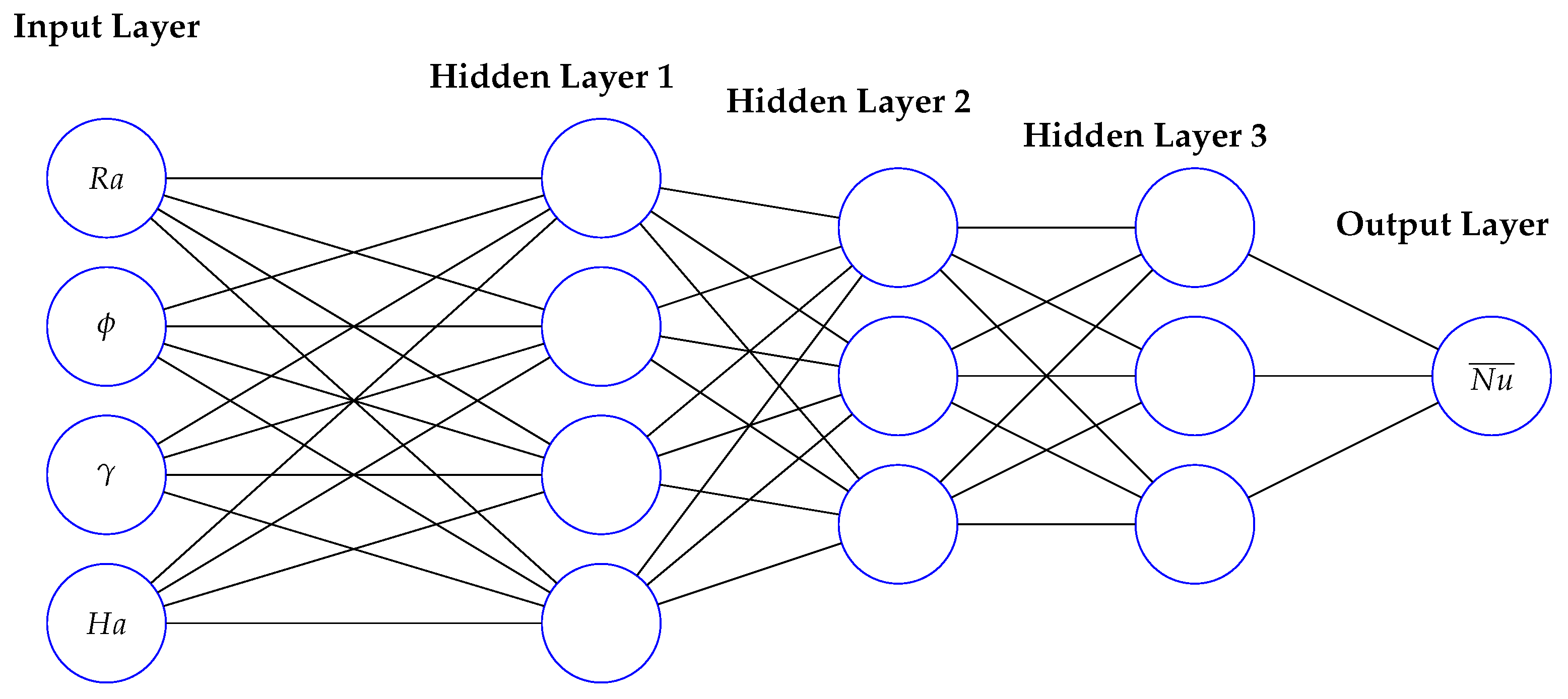
The performance of an artificial neural network (ANN) was examined for predicting the average Nusselt number
based on simulation data. The network architecture, as shown in
Figure 3, featured three hidden layers composed of 25, 20, and 10 neurons, respectively. Training was carried out using the Scaled Conjugate Gradient method, with log-sigmoid functions applied in the hidden layers and a hyperbolic tangent sigmoid function in the output layer. The dataset included 41 samples, of which 29 were used for training and 12 for testing. The learning rate was set to 0.008, and a regularization factor of 0.1 was applied to reduce overfitting.
The architecture of the ANN was carefully tailored to balance learning capacity and generalization. A three-layer configuration with 25, 20, and 10 neurons, respectively, was adopted after performing preliminary hyperparameter sweeps. The choice was motivated by observing diminishing returns in prediction accuracy when additional layers or neurons were introduced, especially given the limited size of the dataset. Activation functions were selected based on the nonlinear nature of the underlying physical phenomena: logsig was employed in the hidden layers to accommodate complex mappings, while tansig was used in the output layer to ensure smooth convergence. To prevent overfitting, a regularization parameter of 0.1 was introduced into the cost function, and this value was empirically adjusted to strike an optimal trade-off between bias and variance. The training process utilized Scaled Conjugate Gradient backpropagation, chosen for its superior convergence speed in moderate-sized networks. This structured optimization ensures that the ANN remains computationally efficient while retaining the fidelity of the original simulation data.
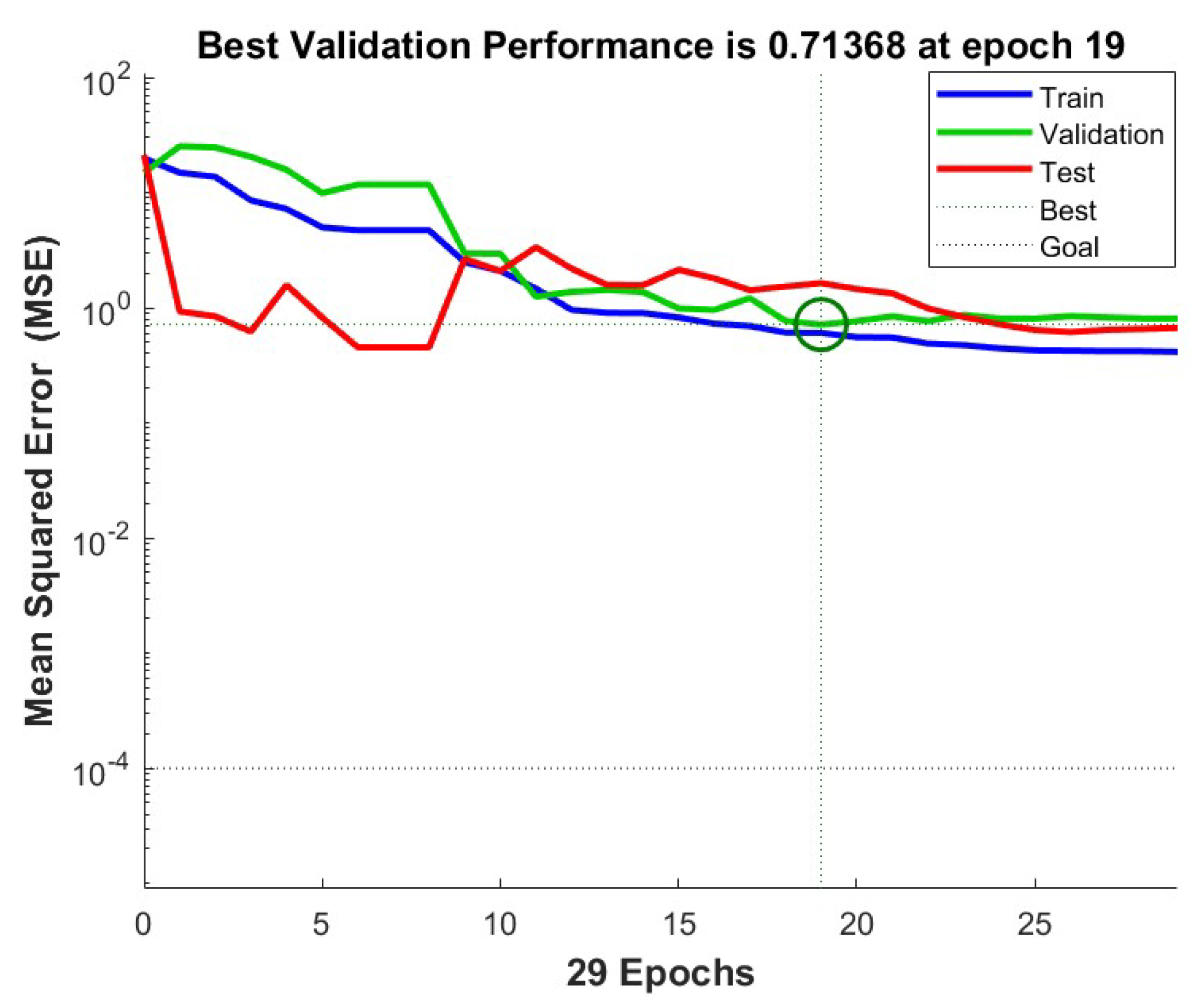
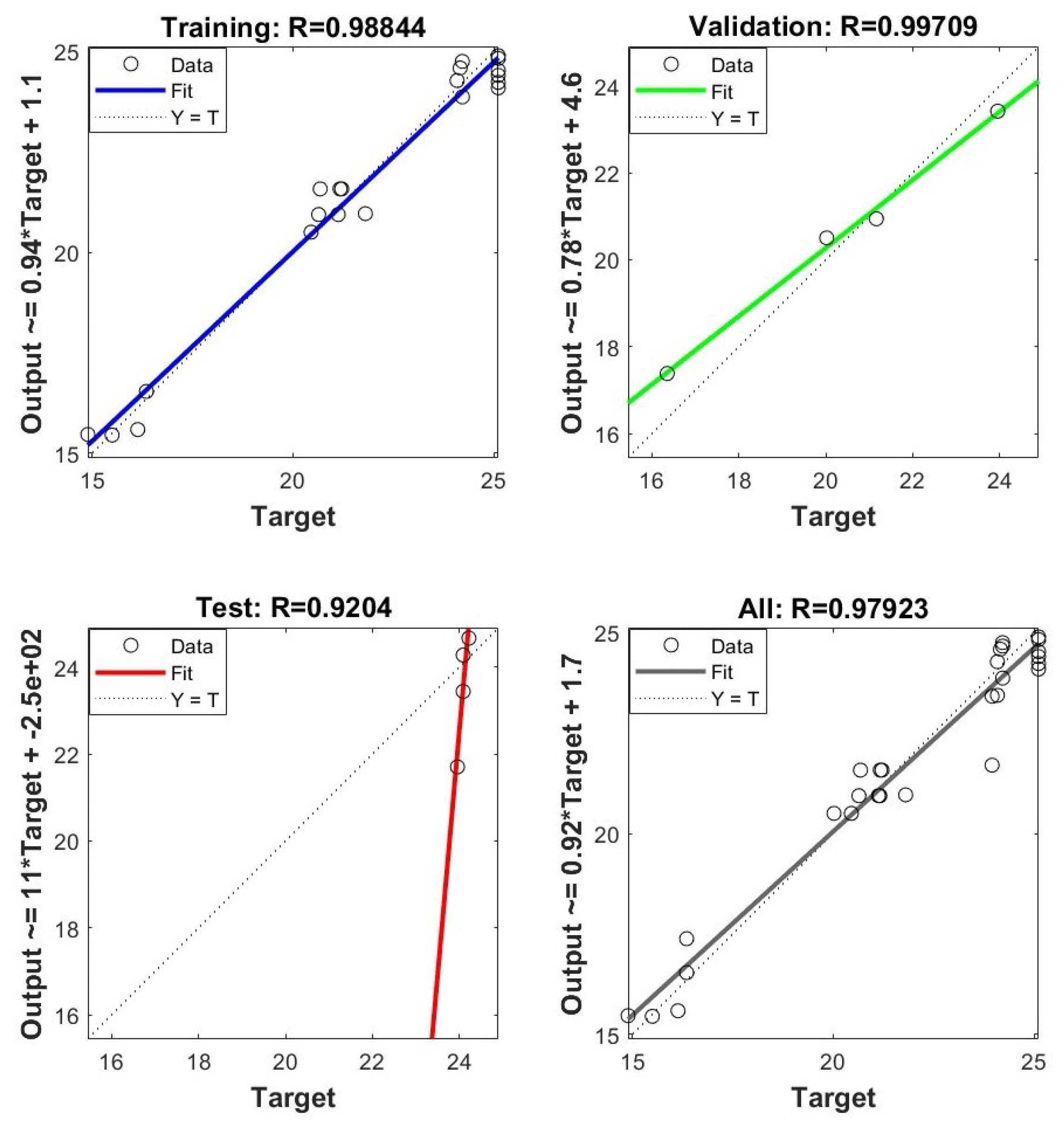
The model was trained for over 2000 epochs and was terminated when the minimum gradient reached or when no improvement was observed in the validation loss for 10 consecutive epochs. The lowest validation error occurred at epoch 19, yielding a mean squared error (MSE) of 0.71368. Regression results reflected strong alignment between the network predictions and the simulation targets, with correlation coefficients of 0.98844 (training), 0.99709 (validation), and 0.9204 (testing), resulting in a combined R-value of 0.97923.
4.1. Performance Evaluation
The accuracy of the ANN model was evaluated using the mean squared error (MSE), which measures the average squared difference between predicted and actual outputs. For the test dataset, the MSE was computed as 1.833811, indicating minimal deviation between the network’s estimates and the reference values. The metric was calculated using the standard expression:
The test result reflects a reliable mapping between the model inputs and the target output, suggesting that the network captures the underlying trends in the dataset effectively. Predicted values closely followed the actual outputs in the testing phase, confirming the ANN’s consistency in handling unseen data within the defined parameter space.
A comparison of actual and predicted
values from the test dataset is presented in the
Table 7:
A scatter plot is used to visualize the correlation between actual and predicted values, as shown in
Figure 4. This plot provides a clear representation of the model’s predictive performance, allowing us to assess the accuracy of the trained neural network model. By comparing predicted outcomes with actual results, we can evaluate how well the model captures the underlying relationships in the data.
The artificial neural network (ANN) produced reliable predictions for the target variable
, with a test set mean squared error (MSE) of 1.833811. The best validation outcome was recorded at epoch 19, where the MSE reached a minimum of 0.71368.
Figure 5 shows the ANN optimal validation performance. The model architecture, which includes three hidden layers with 25, 20, and 10 neurons, was able to identify underlying patterns in the data. The choice of activation functions and the use of the Scaled Conjugate Gradient optimization method contributed to the model’s accuracy. Regression analysis yielded high correlation values across all phases:
for training,
for validation, and
for testing, resulting in an overall correlation coefficient of
.
Figure 6 depicts the relationship between actual and predicted values. A visual analysis of actual versus predicted values reveals a clear relationship, supporting these findings. These values indicate a consistent linear relationship between predicted and actual Nusselt numbers.
4.2. Alternative Input Consideration and Updated ANN Performance
The ANN model was revised by substituting the Rayleigh number () with categorical indices representing Cases I through IV, each corresponding to a distinct thermal boundary configuration. This adjustment led to improved predictive behavior. The revised network architecture included three hidden layers with 30, 20, and 10 neurons. A total of 79 data samples were used, with 55 for training and 24 for testing. The model achieved a mean squared error (MSE) of 9.198536, with the best validation result recorded at epoch 46, where the MSE reached 1.7212. Introducing geometric case identifiers as inputs enabled the network to better capture variations in boundary-driven heat transfer. Correlation coefficients from regression analysis were for training, for validation, and for testing. These results indicate that the case-based input structure supports more accurate predictions of compared with models relying on as an input parameter.
4.3. Regression Analysis for Prediction
A multiple linear regression model was formulated to estimate the Nusselt number based on the Rayleigh number (), Hartmann number (), and thermophysical variables and . Separate regression equations were developed for four thermal boundary configurations, as well as for a unified model incorporating all cases. The resulting expressions are given below:
Statistical Diagnostics of Regression Model: To evaluate the robustness and interpretability of the linear regression model developed for predicting the average Nusselt number (
), a detailed statistical assessment was conducted. This includes estimation of 95% confidence intervals, hypothesis testing using
p-values, and examination of multicollinearity using Variance Inflation Factors (VIFs). The results are summarized in
Table 8 and
Table 9.
Interpretation of Regression Findings: The linear regression model for the Nusselt number exhibits physically consistent and statistically supported trends. The Hartmann number () demonstrates a highly significant negative coefficient (), indicating that increased magnetic field strength suppresses convective heat transfer—an effect attributable to the Lorentz force. The Rayleigh number () shows a significant positive relationship, confirming its role as the primary driver of buoyancy-induced flow, though its numerical impact is small due to scaling. The nanoparticle volume fraction () also significantly enhances heat transfer (), consistent with established findings in nanofluid literature. On the other hand, the inclination angle () is statistically insignificant within the linear framework (), suggesting that its influence may be nonlinear or coupled with other effects. Additionally, all predictors exhibit VIF values below 1.1, confirming minimal multicollinearity and thus ensuring the interpretability and reliability of the regression coefficients. Despite these strengths, the moderate value implies that a purely linear model cannot fully capture the system’s complexity. This motivates the use of ANN-based models in the subsequent section, which are better suited for representing higher-order interactions and nonlinear dynamics.
The coefficients in these expressions reflect the relative influence of each parameter across different configurations. The variable plays a prominent role, with its contribution switching sign depending on the thermal arrangement. The term contributes positively across all cases, while consistently appears with a negative coefficient, suggesting a dampening effect on convective transport. For the general model, the mean squared error (MSE) was calculated to be 0.9763. The coefficient of determination, , suggests that a substantial portion of the variation in is captured by the regression framework. These values reflect a reasonable degree of alignment between predicted outcomes and observed simulation data.
To further assess the model’s generalization performance and mitigate concerns related to overfitting—especially given the limited dataset size—a 5-fold cross-validation procedure was conducted. In this approach, the dataset was randomly partitioned into five equal-sized subsets. The network was trained on four subsets and tested on the remaining one, iteratively rotating the test fold. The resulting mean squared error (MSE) values for each fold are listed in
Table 10. The relatively consistent MSE values across folds indicate that the ANN exhibits stable predictive performance and does not overfit the training data.
Cross-validation applied to the regression model yielded an average mean squared error (MSE) of 0.6611, which is notably lower than the MSE observed in the initial train/test partition. This outcome reflects consistent predictive behavior across different subsets of the dataset. To support the evaluation, an artificial neural network (ANN) was also trained using the same input-output pairs. The comparison of model performance is summarized in
Table 11.
The ANN model produced an MSE of 1.198, whereas the regression model yielded a lower cross-validated MSE of 0.6611. This reduction indicates greater consistency and error resilience in the linear model under repeated sampling. All folds in the cross-validation procedure resulted in MSE values below 1, demonstrating stable behavior across partitions. Based on these metrics, the linear regression model provides better alignment with the dataset’s underlying patterns compared with the ANN under the same experimental conditions.
4.4. Sensitivity Analysis of Hyperparameters
To verify the robustness of the ANN model, a series of sensitivity tests were conducted by systematically varying key hyperparameters. Specifically, the number of neurons per hidden layer was adjusted in the range of 10–40, and alternative activation functions such as
tansig and
purelin were explored. Similarly, the regularization coefficient was varied from 0.01 to 0.2 in increments of 0.05. For each setting, the model was trained using consistent training-testing splits, and the resulting mean squared error (MSE) and R
2 values were recorded. The tabulated outcomes of this analysis are provided in
Table 12, which demonstrate the ANN’s consistent performance across configurations. The model exhibited only marginal variations in performance (less than 5% deviation in MSE), indicating that the network’s predictive accuracy is not highly sensitive to small architectural perturbations. This confirms that the final configuration adopted in this study represents a locally stable and generalizable solution for the problem under investigation.
5. Results and Discussion
This section is devoted to the detailed discussion of simulations predicting the impacts of different pertinent parameters on the flow and thermal distributions, as well as the thermal transport rates, a quantity of paramount interest to the design engineers. In particular, in this analysis, the impact of dual thermal source–sink positioning on the flow and thermal distributions, as well as thermal transport rates, is examined. In addition to the source–sink positioning impacts, MF inclination and NP shape have significant impacts on the hydrodynamic and thermal characteristics of H2O-Ag-TiO2 hybrid NF. The range of parameters considered in this analysis is , , . Further, to elucidate the influence of NP shapes, five different shapes, such as cylinder, platelet, sphere, brick, and blade, have been considered. Throughout the current parametric analysis, the following quantities are maintained at constant magnitude: Prandtl number , aspect ratio , radius ratio , source–sink length , and source–sink positions . Throughout this investigation, all simulations correspond to the Case-1 heating configuration and spherical shape NP as the baseline scenario, except where explicitly indicated otherwise.
5.1. Flow and Thermal Contours
This section depicts a comprehensive analysis of different parametric influences on hydrodynamic flow patterns and thermal distributions for four heating configurations and five NP morphologies.
5.1.1. Impact of Different Heating Conditions on Flow and Thermal Contours
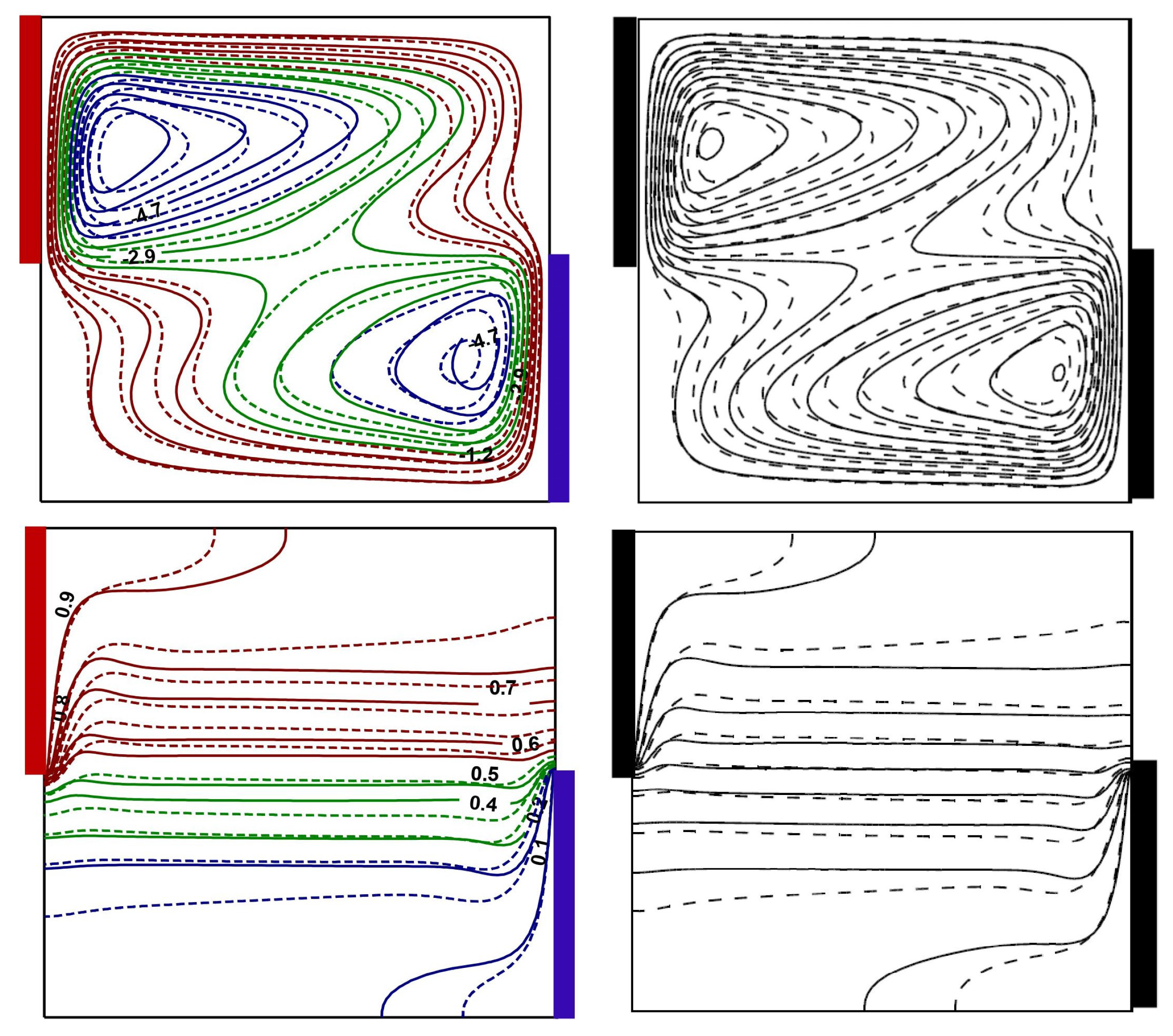
Figure 7 illustrates the profound influence of thermal source–sink positioning on the flow and thermal distributions in both water and Ag-TiO
2 hybrid NF under identical operating conditions (
,
,
). In Case-1, a singular dominant vortex has appeared, characterized by high-intensity vortical motion with the extreme streamline magnitude of
), and a vivid thermal stratification pattern from heated to cooled regions. The transition to Case-2 reveals the bifurcation of flow into dual counter-rotating cells, significantly altering the thermal transport mechanism as evidenced by the modified thermal contours. Cases 3 and 4 demonstrate a different flow mechanism with the formation of quadrant-structured multicellular convective patterns. This kind of vortex restructuring fundamentally changes the heat transfer pathways through the domain. Notably, the hybrid NF (dotted lines) consistently exhibits modified flow patterns and thermal contours compared with pure water (solid lines), with generally enhanced thermal transport capacity as indicated by the isotherm clustering near the sources. The MF (
) exerts a stabilizing impact on the flow, specifically visible in the symmetrical arrangement of circulation cells in Cases 3 and 4.
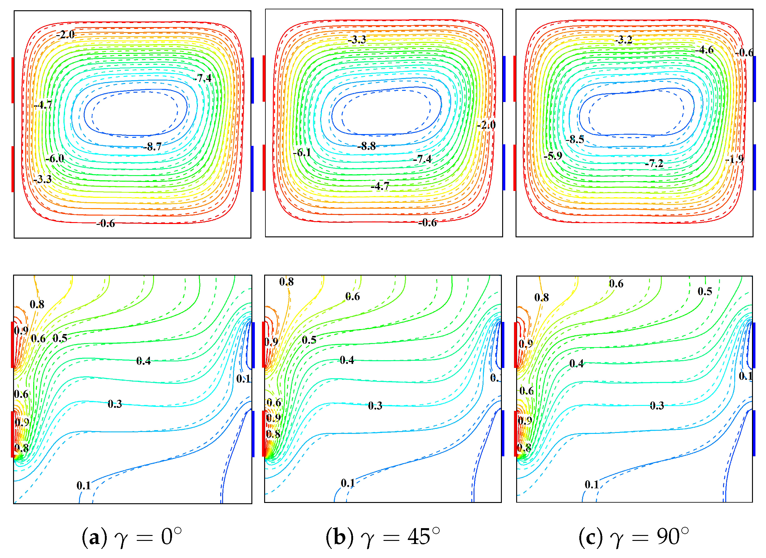
5.1.2. Impact of Magnetic Field Inclination Angle on Flow and Thermal Contours
The significant influence of magnetic tilting angle
on flow and thermal patterns with two different NPs, namely cylindrical and brick-shaped NPs at
and
, is demonstrated in
Figure 8. As
increases from
to
, a progressive reduction in the primary circulation cell strength has been observed, as evidenced by the decrement in streamline magnitude
. This flow weakening may be expected due to the progressive alignment of MF orientation with the direction of buoyancy-driven flow, thereby enhancing the retardation effect by the Lorentz force. In addition, the thermal boundary layers adjacent to the active walls exhibit subtle restructuring at higher inclination angles, indicating a lowered thermal transport. The comparison between cylindrical (solid lines) and brick-shaped NPs (dotted lines) reveals that particle morphology moderately modulates both flow and thermal distribution patterns, with brick-shaped NPs causing slightly modified flow structures due to their anisotropic thermal conductivity characteristics.
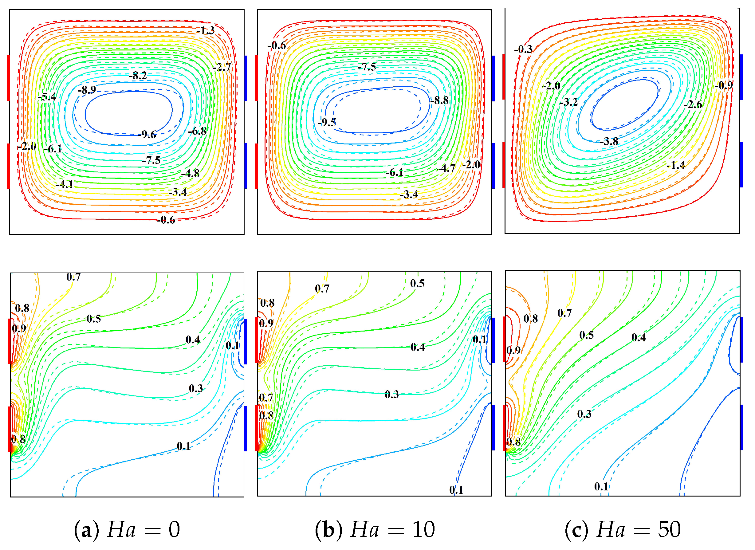
5.1.3. Combined Impacts of Magnetic Field Strength and NP Shape on Flow and Thermal Contours
The profound influence of MF strength, characterized by
, on the hybrid NF buoyant flow and thermal distributions containing cylindrical and brick-shaped NPs has been illustrated in
Figure 9 at
and
. In the absence of MF
, a robust single-vortex circulation structure has been observed with a maximum streamline magnitude
of
, driven solely by buoyancy forces. As
increases to 10, the Lorentz force begins to counter the buoyancy-driven motion, evidenced by the suppression in circulation intensity (
) and exerts subtle modification on isotherm patterns. At
, the magnetic damping effect becomes dominant, considerably suppressing the convective motion (
) and substantially restructuring the flow field. Concurrently, the isotherms progressively transform from the convection-dominated pattern at
to a more conduction-like structure at
, particularly visible near the thermal sources. The comparison between cylindrical (solid lines) and brick-shaped nanoparticles (dotted lines) reveals modest but visible differences in both flow and thermal structures, indicating that nanoparticle morphology also plays a role in modulating the magnetohydrodynamic behavior of the system.
5.1.4. Influence of NP Shape on Flow and Thermal Contours
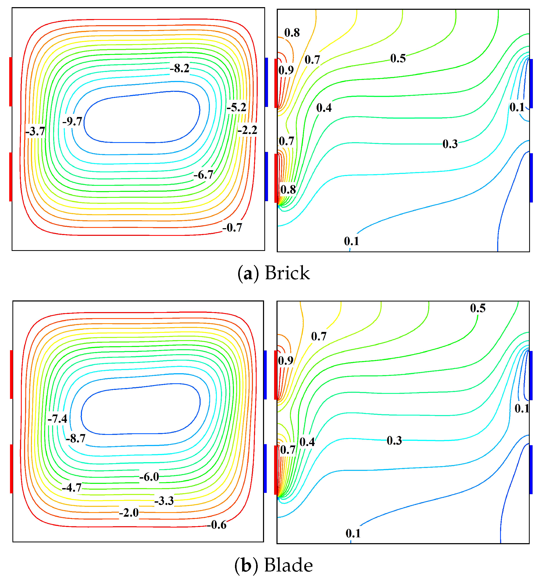
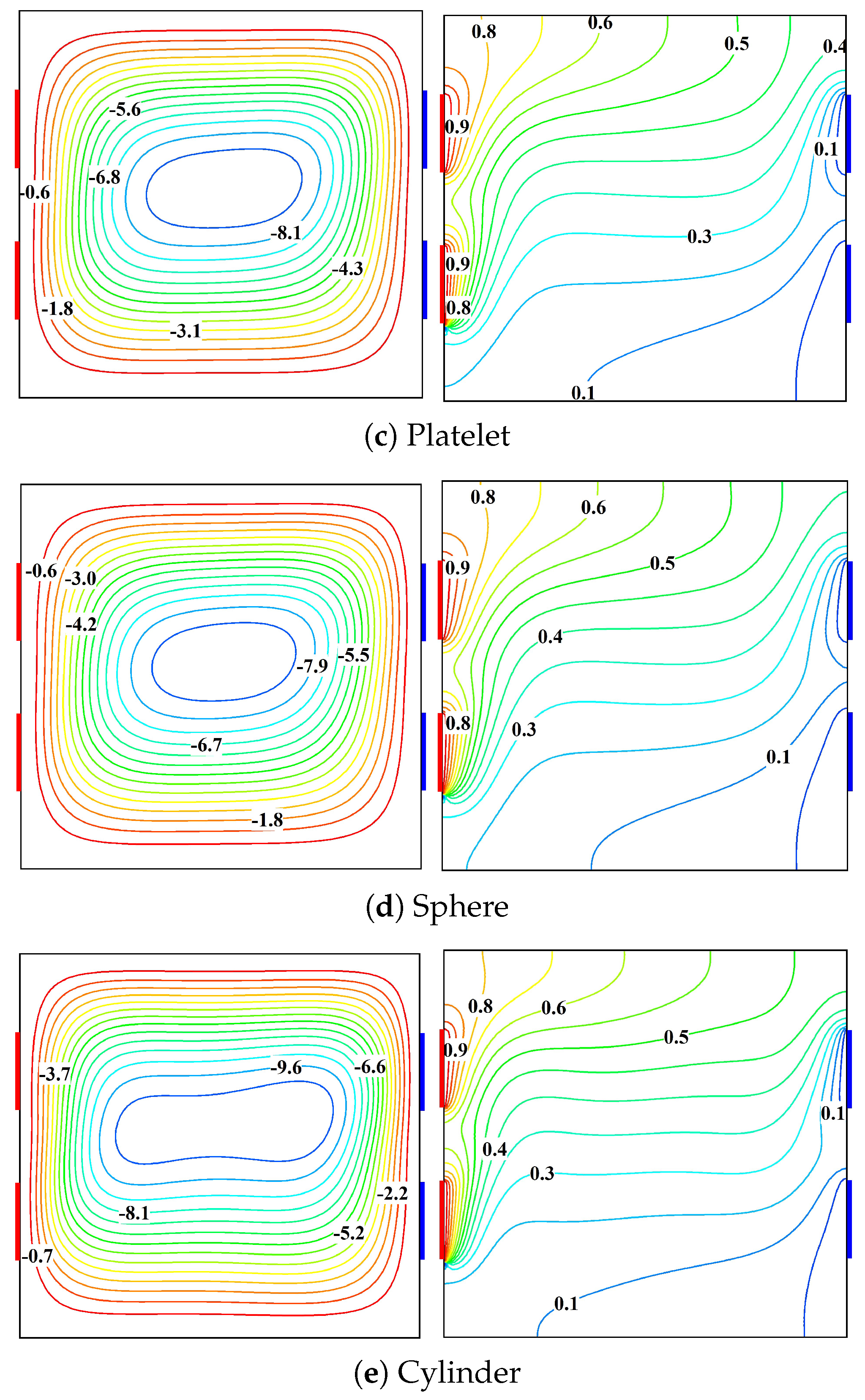
Figure 10 illustrates a comprehensive visualization of nanoparticle morphology influences on the thermo-hydrodynamic characteristics under identical operating conditions at
,
,
,
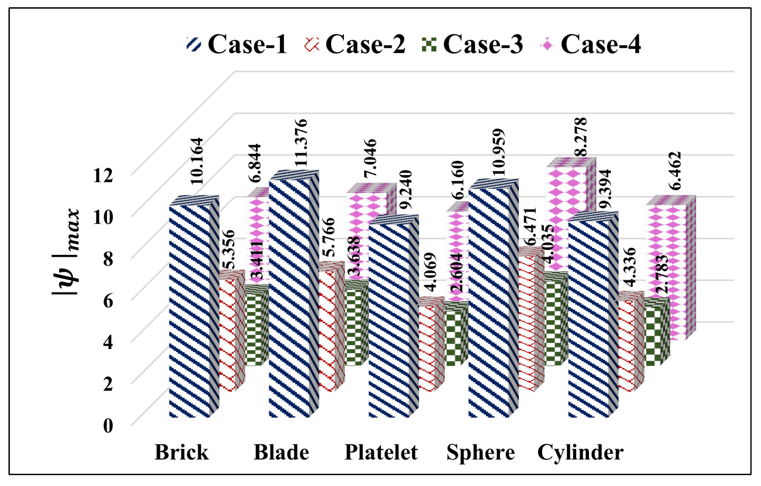
. The most striking observation is the substantial variation in flow intensity across different NP shapes, with brick-shaped particles generating the strongest circulation (
of
) and spherical particles causing the weakest flow circulation (
). Generally, the flow circulation strength often serves as a useful predictor of thermal transport enhancement. However, the relationship should be quantitatively established for each specific nanoparticle type and heating configuration through the estimation of
. This has been performed in a later section by considering wide parameter ranges. This hierarchy of flow intensification could be correlated with the effective thermal conductivity enhancement provided by the NP shape, where non-spherical particles generally offer superior thermal transport characteristics due to their higher surface area-to-volume ratios. The isotherm structure further elucidates these effects, with subtle but important differences in thermal boundary layer thickness and isotherm clustering near the thermally active regions. The variation in isotherm patterns across different NP shapes reflects the complex interplay between particle shape and resulting convective transport phenomena. In particular, non-spherical NPs generally offer superior thermal transport enhancement due to their unique thermophysical characteristics and flow-structure interaction mechanisms.
5.2. Thermal Transport Characteristics
This section mainly aims to illustrate the variation in the quantitative measure of thermal transport under the influence of diverse parameters of the chosen analysis.
5.2.1. Impact of Different Heating Conditions on Thermal Dissipation Rate
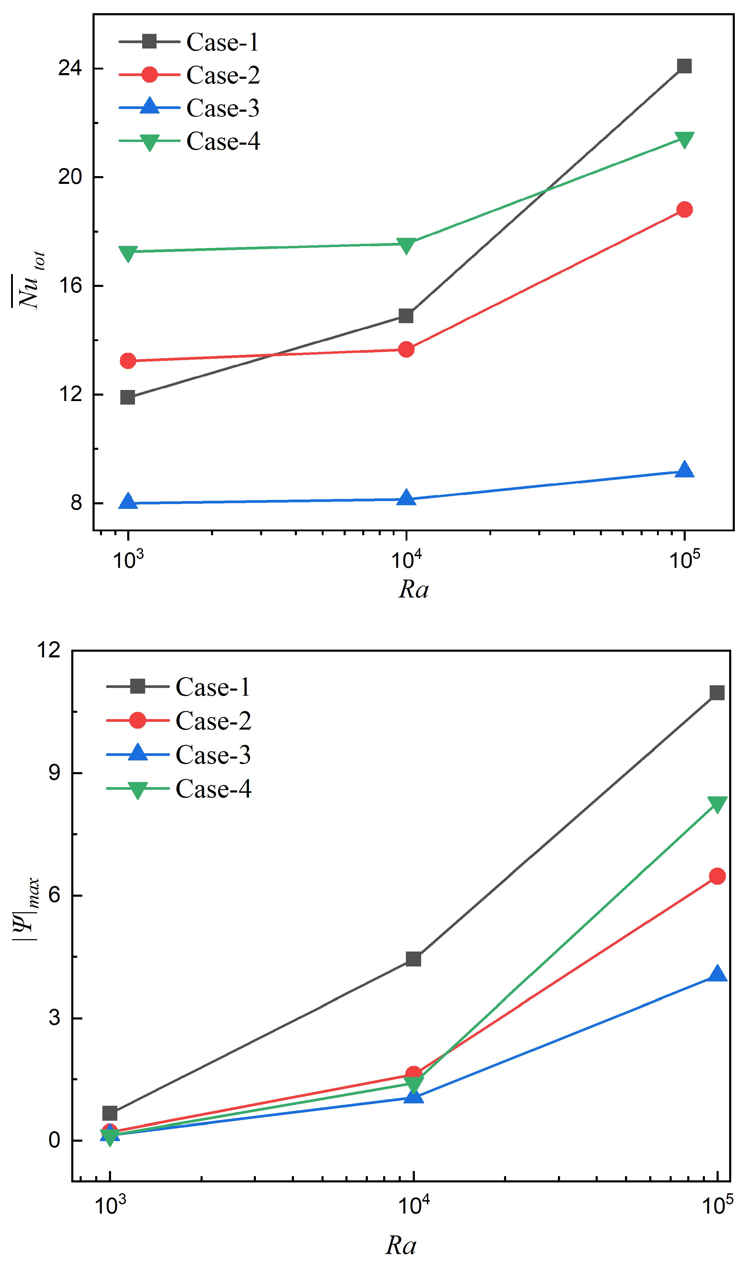
The predictions in
Figure 11 reveal distinctive thermal-hydraulic responses to four different heating configurations across varying buoyancy intensities. In the side heating–cooling positioning (Case-1), thermal transfer performance demonstrates remarkable
sensitivity, transitioning from the lowest
(≈12) at
to the highest (≈24) at
. This configuration generates the strongest circulation patterns at higher
values (
), indicating optimal alignment of temperature gradients with buoyancy-assisted currents in the annular space. Conversely, the upper cooling–lower heating arrangement (Case-4) exhibits superior performance at lower
numbers with minimal
-dependency until
, suggesting its impact in conduction-dominated transport regimes where stratification enhances thermal exchange. The cross heating–cooling configuration (Case-2), establishing the diagonal thermal differences, maintains moderate performance across all
magnitudes, offering more consistent, however, less optimized thermal transfer characteristics. In particular, the upper heating–lower cooling arrangement (Case-3) consistently underperforms at all Rayleigh numbers, with
values approximately
lower than Case-1 at
, indicating that this configuration creates thermally stratified conditions that significantly inhibit buoyancy-driven flows.
5.2.2. Collective Impacts of Different Heating Conditions and on Thermal Dissipation Rate
Figure 12 reveals distinctive responses of thermal transport and flow circulation rate to MF inclinations for the different heating cases. For side heating–side cooling (Case-1), both
(≈24) and flow intensity (
) demonstrate remarkable resilience to MF orientations, maintaining superior thermal performance across all angles. This source–sink arrangement generates robust convective-driven cells aligned favorably with the primary flow direction, making it less prone to magnetic dampening effects. Conversely, upper cooling–lower heating (Case-4) exhibits non-monotonic thermal behavior with peak performance at
(
), followed by gradual decline as
approaches
, accompanied by consistent reduction in flow intensity. Cross heating-cross cooling (Case-2) shows moderate but steady performance deterioration with an increase in
, while upper heating–lower cooling (Case-3) remains consistently ineffective (
) regardless of MF tilting due to thermally unstable stratification that fundamentally suppresses convective motion. These results demonstrate that MF orientation primarily impacts asymmetric heating configurations (Cases 2 and 4) by significantly influencing the balance between Lorentz forces and buoyancy-assisted flows, while symmetric arrangements (Cases 1 and 3) maintain consistent performance characteristics regardless of the MF orientation.
5.2.3. Collective Impacts of Different Heating Conditions and on Thermal Dissipation Rate
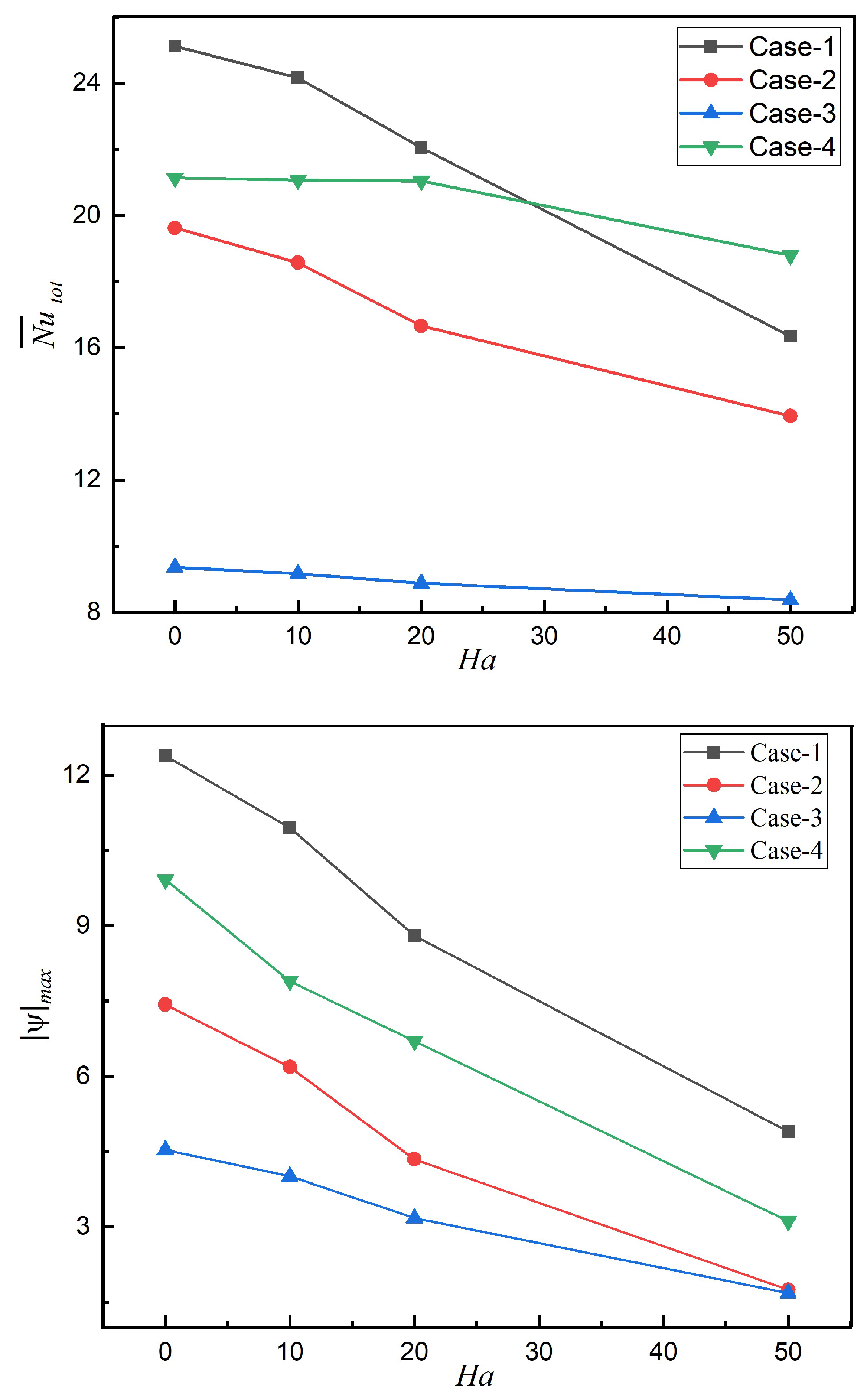
The profound MF impacts on heat transport and flow circulation rates across the different heating arrangements are demonstrated in
Figure 13. Side heating–side cooling (Case-1) exhibits the maximum thermal dissipation rate (
) for
but experiences the most dramatic deterioration (∼36% reduction) as Hartmann number increases to 50. This significant reduction stems from the perpendicular alignment between the induced MF and the primary flow direction, creating higher flow resistance. On the other hand, upper cooling–lower heating (Case-4) depicts remarkable resilience to magnetic drag due to the thermally unstable stratification (cold fluid over hot), and maintains strong buoyancy forces despite substantial MF dampening, and thus becomes a superior configuration beyond
. In general, thermal transport augmentation in all heating cases fundamentally depends on the competition between two forces, namely buoyancy (promoting circulation) and magnetic forces (suppressing motion). Flow intensity uniformly decreases with an increasing
across all arrangements, with magnetohydrodynamic dampening most effective in the arrangements with strong initial circulation. The upper heating–lower cooling arrangement (Case-3) remains consistently lower flow circulation rate regardless of MF strength due to inherently stable thermal stratification that fundamentally suppresses convective motion. These predictions reveal that the MF strength not only suppresses convective heat transfer through Lorentz-force-induced flow deceleration but also reorganizes the competitive hierarchy among different thermal source–sink arrangements.
5.2.4. Collective Impacts of Different Heating Conditions and NP Shape on Thermal Dissipation Rate
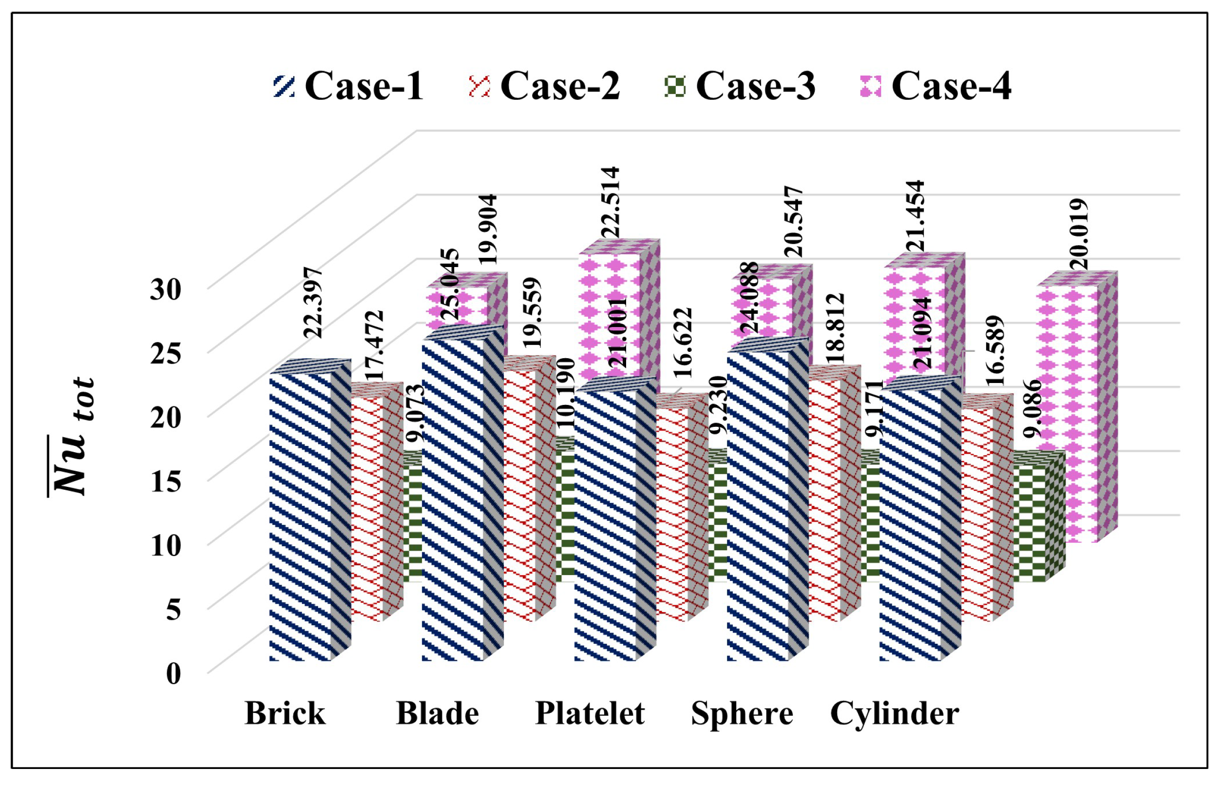
The predictions in
Figure 14 reveal the distinct thermal-hydraulic responses to the shape of NP in four combinations of heating–cooling in
,
,
and
. Among the different NP shapes considered in this analysis, blade-shaped NPs demonstrate superior thermal transfer enhancement (
) for Case-1 (side heating–side cooling), followed by Case-4 arrangements (upper cooling–lower heating) with
, which is attributable to their high aspect ratio for promoting thermal conductivity enhancement. Notably, platelet-shaped particles also exhibit excellent performance in Case-4 (
), while consistently underperforming in other arrangements. Further, flow intensity correlates strongly with the thermal transfer performance, with blade particles generating the strongest circulation in Case-1 (
) and sphere particles producing robust flows in Case-4 (
). Among the different heating–cooling arrangements, the thermally unstable stratification in Case-4 (cold over hot) maintains strong convective performance across all NP shapes, while Case-3 (upper heating–lower cooling) consistently demonstrates the poorest thermal-hydraulic performance due to its inherently stable thermal stratification suppressing buoyancy-driven flows. These outcomes highlight an important conclusion that an optimal NP selection depends critically on the source–sink arrangements, with non-spherical particles offering significant advantages in configurations that promote strong convective currents. The enhanced thermal conductivity of NPs is recognized as the prominent factor driving the thermal performance improvements of NFs over conventional fluids. Our comparative analysis of thermal conductivity across five distinct NP shapes reveals that blade-shaped NPs demonstrate notably superior thermal conductivity magnitudes. This enhanced performance can be attributed to the extended surface area characteristic of blade-shaped NPs, which facilitates improved fluid mobility and heat transfer efficiency. Consequently, the blade-shaped NP emerges as the most effective configuration among the chosen five different NP morphologies for thermal enhancement applications.
5.2.5. Combined Influences of and on Thermal Dissipation Rate
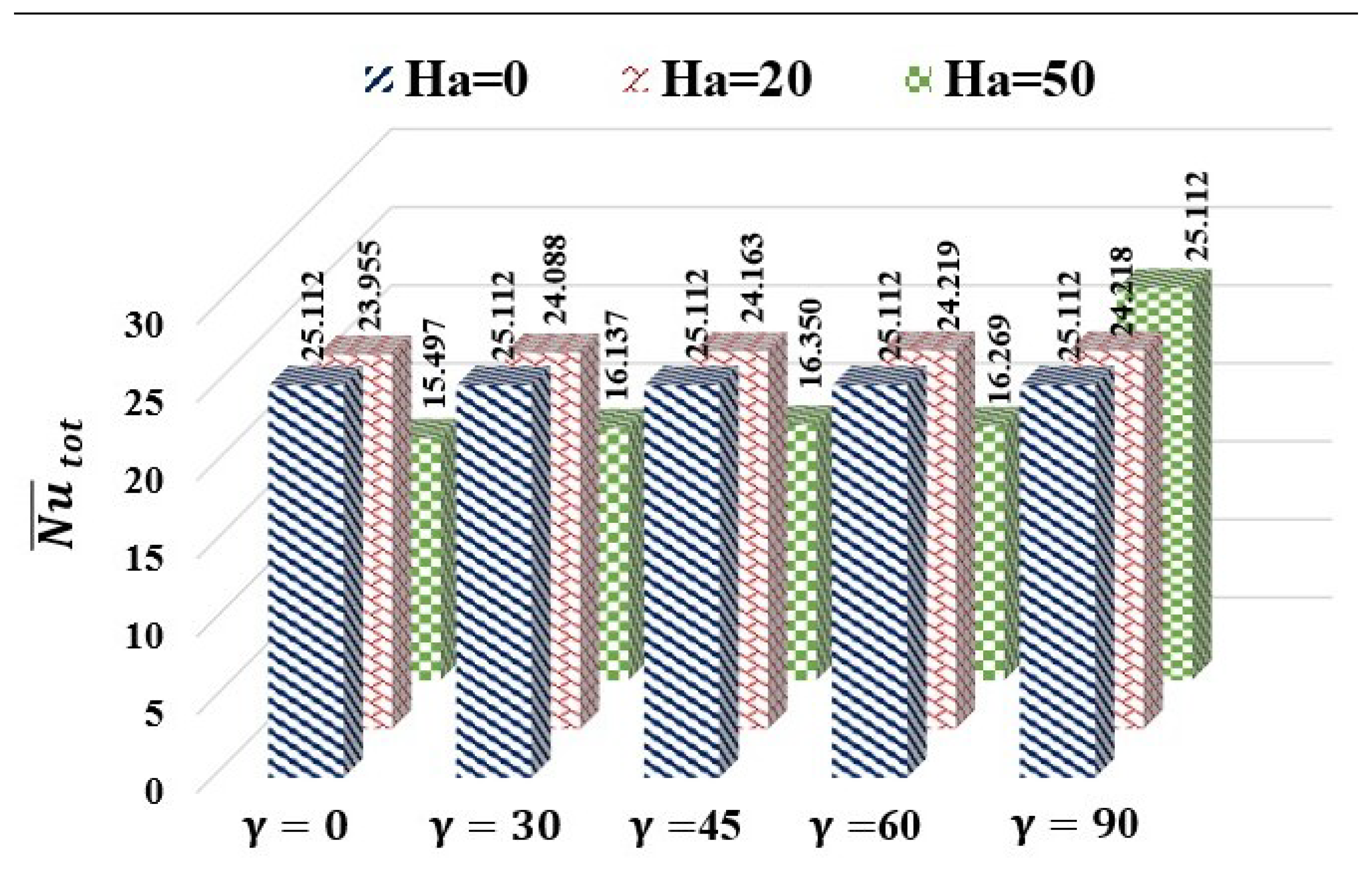
The collective impacts of the MF strength and tilting angle on thermal transport characteristics are shown in
Figure 15 for
and
. These predictions reveal remarkable interactions between MF strength and orientation on thermal transfer for side heating–side cooling arrangements and hybrid NF with spherical-shaped NP. In the absence of MF (
), both the
(
) and flow intensity (
) remain constant across all inclination angles, establishing the baseline performance. At moderate MF strength (
), heat transport declines marginally (∼6%) with minimal angular dependency, demonstrating uniform magnetic suppression. The most striking phenomenon occurs at high MF strength (
), where thermal transport is significantly reduced (∼38%) for inclination angles
, but completely recovers to the baseline values at
. This perpendicular MF orientation creates a unique scenario in which MF lines align parallel to the primary fluid movements established between the discretely heated and cooled boundaries, effectively suppressing the Lorentz-force damping of the main flow. The flow intensity variations precisely mirror the thermal transfer trends, confirming that convective transport remains the dominant thermal transport mechanism.
5.2.6. Impacts of Different NP Compositions on Thermal Dissipation Rate for Various and Heating Conditions
Figure 16a reveals the significant interplay between MF orientation and hybrid NP compositions on thermal transfer performance. Perpendicular MF orientation (
) consistently enhances thermal transfer across all NP combinations, with maximum thermal dissipation rate (
) achieved for pure silver NF. This orientation makes the MF lines align parallel to primary convective currents, thus minimizing Lorentz-force suppression on convective currents. A clear compositional trend emerges wherein increasing silver NP concentration progressively enhances thermal performance, with pure Ag NF outperforming pure TiO
2 NF by approximately
at
. This superiority stems from the substantially higher thermal conductivity of silver NP as compared with titanium oxide NP. The hybrid NP compositions demonstrate intermediate performance, with higher silver NPs yielding better results. Most notably, the performance gap between different MF orientations reduces as silver NP density increases.
Figure 16b reveals that thermal source–sink positioning has a greater influence on thermal dissipation performance than NP composition in hybrid NFs. The predictions clearly illustrate that side heating–side cooling arrangement (Case-1) consistently demonstrates superior performance (
–
) across all compositions, benefiting from strong horizontal thermal gradients driving effective convective movements. Upper heating–lower cooling (Case-3) arrangement persistently exhibits meager thermal dissipation rates (
–
) due to a stable thermal stratification structure that substantially suppresses the buoyancy-assisted flows. Regarding NP composition impacts, increasing silver concentration marginally enhances heat transfer across all configurations (2–3% improvement from pure TiO
2 to pure Ag), attributable to silver’s superior thermal conductivity. This modest improvement suggests that at
and
, convective thermal transport remains dominant, with source–sink arrangement primarily determining thermal performance than NP composition.
