1. Introduction
The oil well casing, a critical structural component in oil and gas well drilling engineering, is composed of hundreds of individual pipe sections or casing strings, primarily serving to support the wellbore walls and ensure the stability and integrity of the wellbore [
1,
2,
3,
4]. The stability of the casing is of critical importance to the smooth drilling process and long-term, stable production of oil and gas wells. However, fluctuations in the bottomhole pressure during drilling and completion operations, coupled with complex external loading conditions, pose significant challenges to the stability of the casing strings [
5]. Especially at the connection points of the casing strings, the abrupt changes in geometric configurations can easily lead to stress concentration under external loading conditions, making these areas the weakest links in the entire casing system and significantly increasing the risk of failure at the connections [
6]. According to statistical data, approximately 60% of oil casing instability incidents involve failure points located at the connections. Therefore, optimizing connection performance and enhancing connection stability are of utmost importance in reducing the risk of casing string failure and ensuring the smooth implementation of oil and gas production engineering projects.
Threaded connections serve as the primary method for connecting oil well casings, and their performance optimization is of vital importance [
7,
8,
9]. The connection strength, gas tightness [
10], and anti-galling reliability of the connection sections are all critical determinants of the overall performance of the casing system. Currently, API connections represent the primary form of threaded connections, offering high structural strength to withstand conventional pressure conditions. However, the inferior gas tightness of API connections necessitates their dependence on thread grease to achieve gas tightness [
11,
12]. Within oil and gas well environments, prolonged exposure to chemical erosion, temperature fluctuations, and pressure variations can gradually diminish the sealing efficacy of these thread compounds. As a result, the sealing and connection performance of the API connection are no longer sufficient to meet the operational demands of oil well tubular systems, making them prone to connection failure, leakage, and other risks [
13].
In recent years, China has significantly increased investments in the development of complex oil and gas wells [
14,
15], including high-temperature and high-pressure (HTHP) wells and deepwater/ultra-deepwater environments, while continuously raising technical requirements for extraction operations.
These advancements have led to heightened demands for enhanced performance in threaded oil well casing connections. Conventional connections struggle to adapt to the complex downhole conditions, leading to the emergence of specialized threaded connections characterized by high gas tightness and superior torsional resistance [
8,
16,
17].
Since the early 20th century, specialized gas-tight threaded connections for oil well casings have gradually gained prominence in petroleum engineering fields across Western countries [
4,
13,
18,
19,
20,
21,
22]. Pioneering companies such as ATLAS BRANDFORD and HYDRIL in the United States had already developed and patented over a dozen products as early as the 1960s. With continuous technological advancements, major global oil casing manufacturers have successively produced various types of gas-tight threaded connections, which are renowned for their exceptional performance and reliability, and are now widely applied in major oilfields worldwide. Currently, gas-tight threaded connection products from companies such as VAM (Vallourec) in Europe, Hunting and Hydril in the U.S., and Tenaris in Argentina dominate the global market, achieving exceptionally high levels of service life and operational stability [
23]. These advanced products have been extensively adopted and utilized in numerous domestic oil fields.
Table 1 lists several representative international gas-tight threaded connection products and their manufacturers. Despite advancements in premium connections, critical gaps persist in understanding synergistic temperature–pressure effects on sealing performance evolution. Current studies predominantly focus on single-factor analysis, while actual downhole conditions present coupled thermo-mechanical loading cycles that accelerate sealing degradation through synergistic mechanisms not yet quantified.
China’s research and development of gas-tight threaded connections started relatively late, with most such connections used in major oil and gas fields since 1981 sourced from Western countries. However, as China’s oil production technologies matured, its numerous unique hydrocarbon reservoirs became distinct from those in other nations. For instance, in its four major maritime regions (East China Sea, South China Sea, Bohai Sea, and Yellow Sea), China has identified increasing numbers of in situ pyrolysis wells [
24] for organic-rich shale conversion [
18,
25,
26,
27], high-temperature/high-pressure deepwater wells [
28,
29,
30], heavy oil thermal recovery wells [
31,
32,
33,
34], and challenging wells operating in corrosive environments with H
2S and CO
2. This has driven a growing demand for high-performance, high-strength gas-tight threaded connections [
9,
35,
36,
37,
38,
39]. Existing models fail to predict multi-cycle gas-tightness decay patterns under combined thermal cycling and pressure fluctuation conditions. This knowledge gap directly impacts connection design optimization for extreme service conditions, particularly in China’s unique reservoirs (e.g., thermal recovery wells with 450 °C steam injection and ultra-deep HPHT wells exceeding 200 MPa).
In recent years, China has initiated independent R&D efforts for gas-tight threaded connection products [
22,
40]. Companies such as Baoshan Iron & Steel [
41,
42], Tianjin Pipe, Wuxi Simles, and CNOOC Energy Equipment & Technology have achieved significant advancements in this field, successfully developing high-standard special threaded connection products.
Table 2 lists domestic manufacturers and their special threaded connection products in China.
Complex downhole environmental conditions pose significant challenges to the gas tightness and strength of threaded connections. High-seal-performance special threaded connections, possess unique sealing structures and torque shoulders, enabling them to maintain high sealing integrity and mechanical strength under high-temperature and high-pressure conditions without degradation of connection engagement or sealing failure during long-term service. Limited research exists on the design and application technologies of gas-tight threaded casing connections, making performance evaluations of their sealing capabilities critical for theoretical and engineering advancements in connection design optimization.
Several emerging technologies show potential for enhancing threaded connection performance in extreme environments. For novel thread geometries, bio-inspired asymmetric profiles (mimicking conch shell microstructures) with variable flank angles (25–40°) are being developed to optimize load distribution under thermal cycling conditions. In terms of materials, shape memory alloy (SMA) seals that self-adjust interference fit via temperature-induced phase transitions (e.g., NiTi-based alloys with 5–8% strain recovery) could mitigate leakage from thermal stress. Advanced ceramic coatings (e.g., Al2O3-TiO2 composites) with thicknesses of 50–100 μm also offer improved wear and corrosion resistance, extending seal lifespan in H2S/CO2 environments.
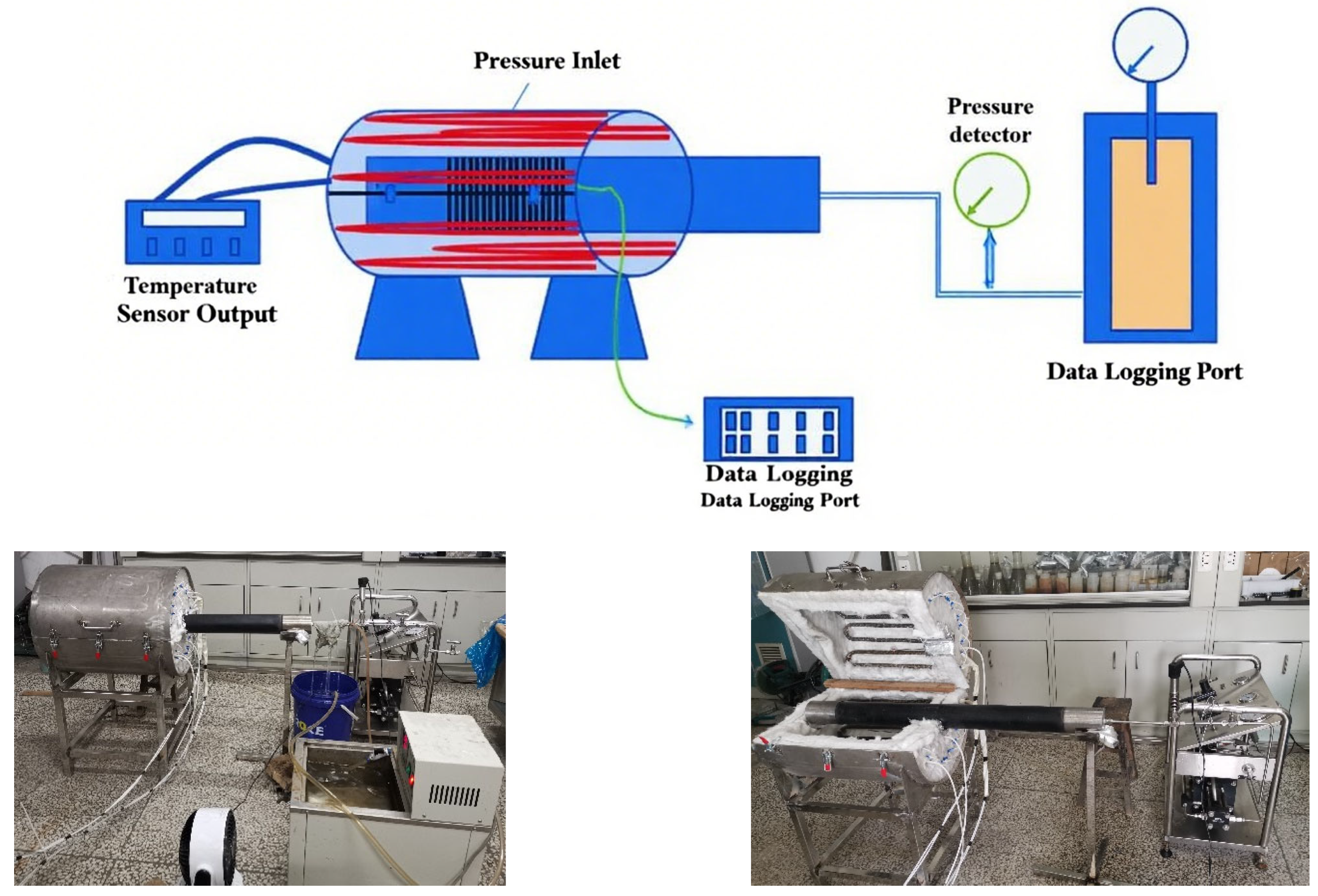
In summary, experimental setups and evaluation methodologies were designed in this study based on three representative temperature–pressure conditions (50 °C/21 MPa, 350 °C/21 MPa, and 450 °C/7 MPa) to simulate extreme downhole environments encountered during oil and gas drilling and production. These parameters were determined based on statistical analysis of field data from domestic key oil and gas fields (such as Sichuan Basin ultra-deep wells and Bohai Bay heavy oil fields) and references to industry standard test conditions (API RP 5C5). The 50 °C/21 MPa condition represents shallow or conventional well sections, assessing sealing stability under baseline loads. The 350 °C/21 MPa scenario mimics deep high-temperature and high-pressure reservoirs (e.g., shale gas or ultra-deepwater wells), where coupled thermal and pressure stresses induce stress concentration and sealing failure, critical for evaluating connection performance under extreme conditions. The 450 °C/7 MPa condition targets high-temperature scenarios with fluctuating pressures, such as heavy oil thermal recovery or geothermal wells, simulating material degradation caused by chemical corrosion and thermal cycling. This combination spans a continuous spectrum from ambient to extreme temperatures (450 °C) and pressures (21 MPa to low-pressure conditions), with cyclic testing replicating the cumulative effects of alternating temperature–pressure regimes and long-term operational exposure. The experimental framework ensures direct applicability to complex reservoir development strategies.
While existing studies have established baseline sealing performance metrics for casing connections, they predominantly focus on static conditions or single factor loading scenarios (e.g., high pressure or high temperature alone). This creates a critical research gap in understanding the synergistic degradation mechanisms under combined thermal cycling and pressure fluctuation conditions—a condition prevalent in ultra-deep and thermal recovery wells. Our study addresses this gap through three innovations: (1) a novel multi-cycle testing protocol simulating realistic downhole thermo-mechanical coupling; (2) quantitative leakage analysis using ideal gas-law-based modeling. These advancements provide actionable insights for optimizing sealing designs in complex reservoirs, which aim to provide critical data support for China’s oil and gas field development, particularly for the efficient exploitation of complex reservoirs.
3. Results and Discussion
3.1. High-Temperature Gas-Tightness Analysis of 511 Direct Threaded Connection
The 511 direct-connect thread, as a special threaded connection method, achieves secure fixation of connected components through the resistance between threaded connections (
Figure 2). It possesses high strength and reliability, offering advantages in ease of disassembly and replacement, which facilitates maintenance and repair. The connection method of the 511 direct threaded connection is particularly suitable for mechanical connection applications that are required to withstand high pressure or vibration. Additionally, its installation process does not require specialized equipment or skills, being relatively simple and quick. Its specification parameters include thread diameter, pitch, thread form angle, and others, which can be selected based on specific application scenarios and connection requirements. Thanks to these characteristics, the 511 direct-connect thread is widely applied in the connection of critical components such as tubing and casing, ensuring the smooth progress of drilling operations.
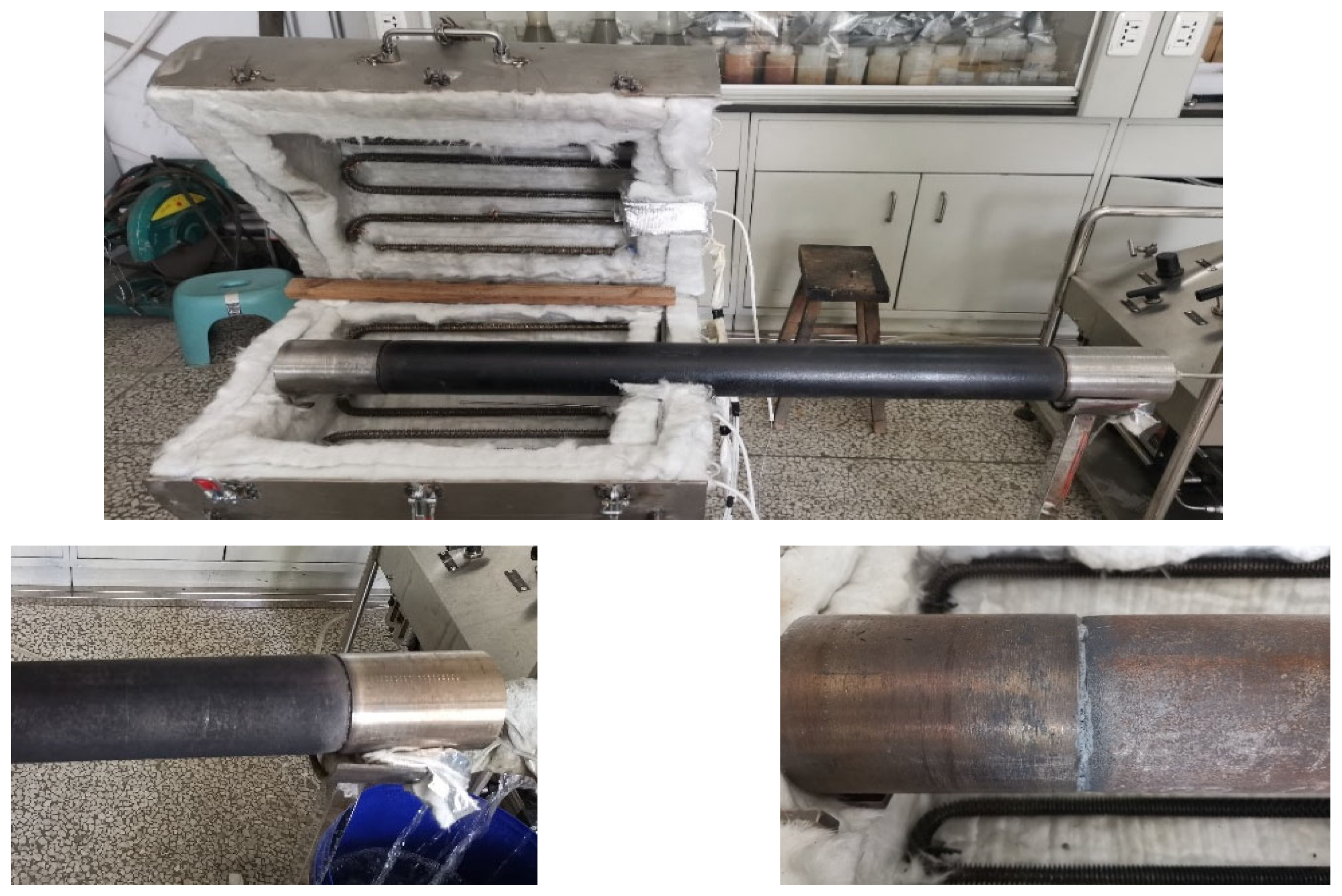
The photographs of the 511 straight-through threaded connection specimens before and after testing are shown in
Figure 3. The comparison reveals that prolonged high-temperature exposure caused the formation of black carbon residues on the surface of the tubular components, while the sealant at the connection areas underwent carbonization at elevated temperatures. The following sections provide a detailed analysis of the gas-tightness performance of the specimens under various temperature–pressure conditions.
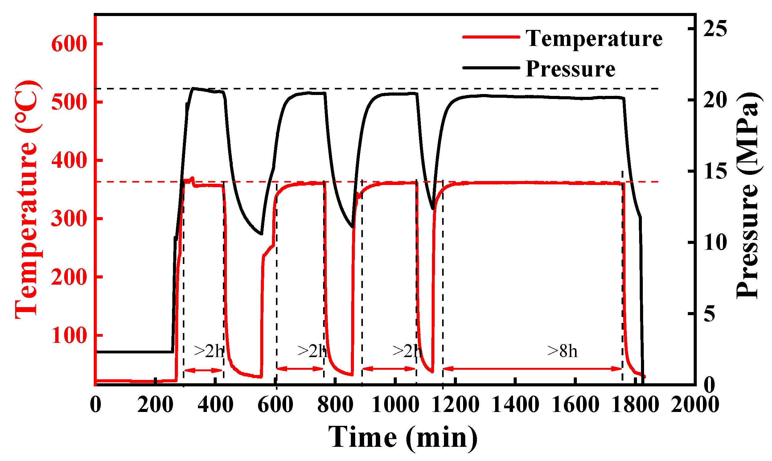
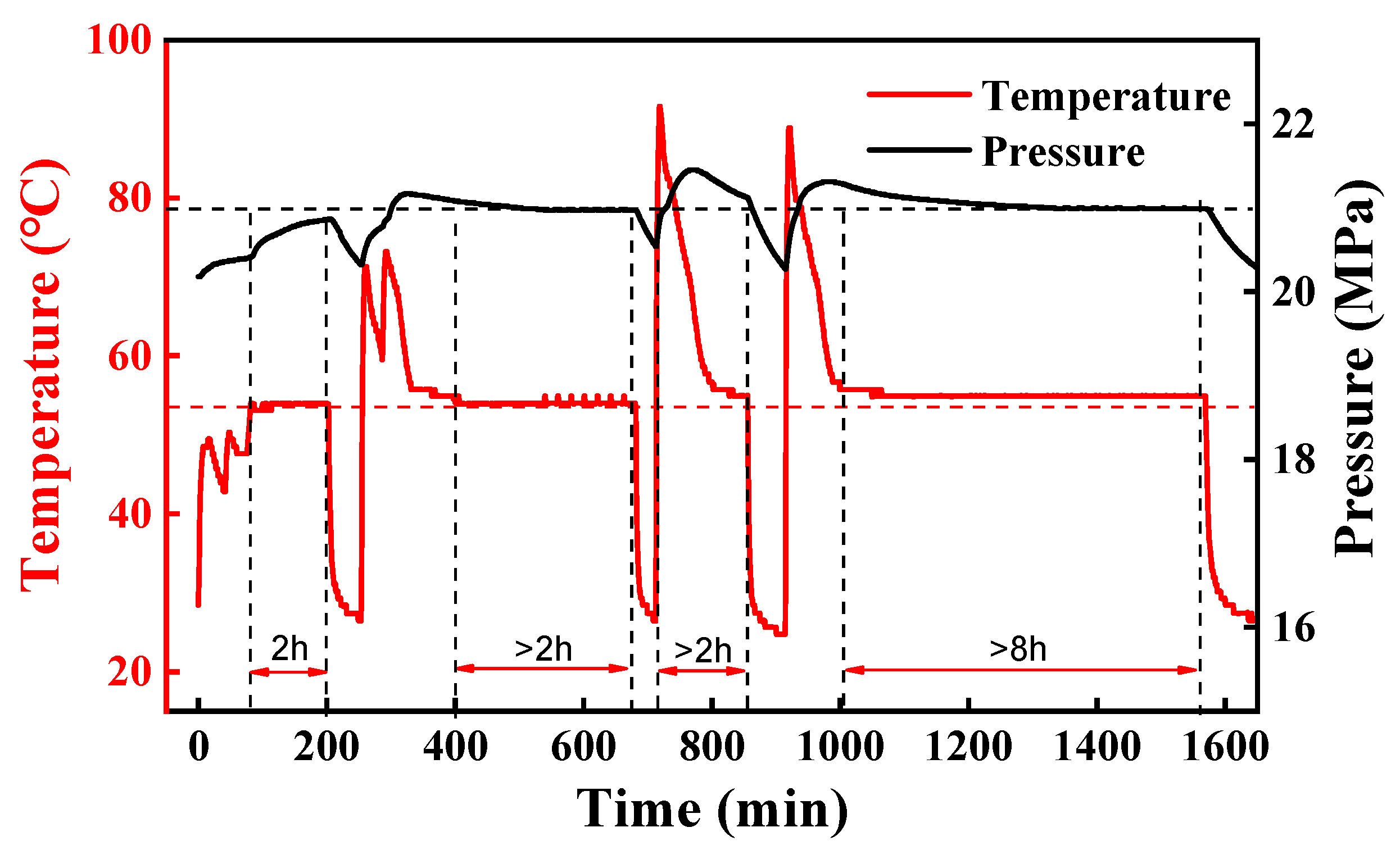
The dynamic curves of temperature and pressure changes for the 511 direct-connect threaded connection under 50 °C and 21 MPa test conditions (three cycles of heating and 8 h of stabilization) are shown in
Figure 4. Due to the relatively low temperature of 50 °C, the heating process with the temperature controller exhibited significant fluctuations, particularly during initial heating when instantaneous temperature spikes reached 80 °C. The temperature gradually stabilized as heating continued. As illustrated in
Figure 4, the internal tubing pressure correlated directly with temperature changes: pressure increased as temperature rose and stabilized once temperature equilibrium was reached. However, the temperature and pressure curves alone do not clearly indicate any leakage occurrences in the test specimens.
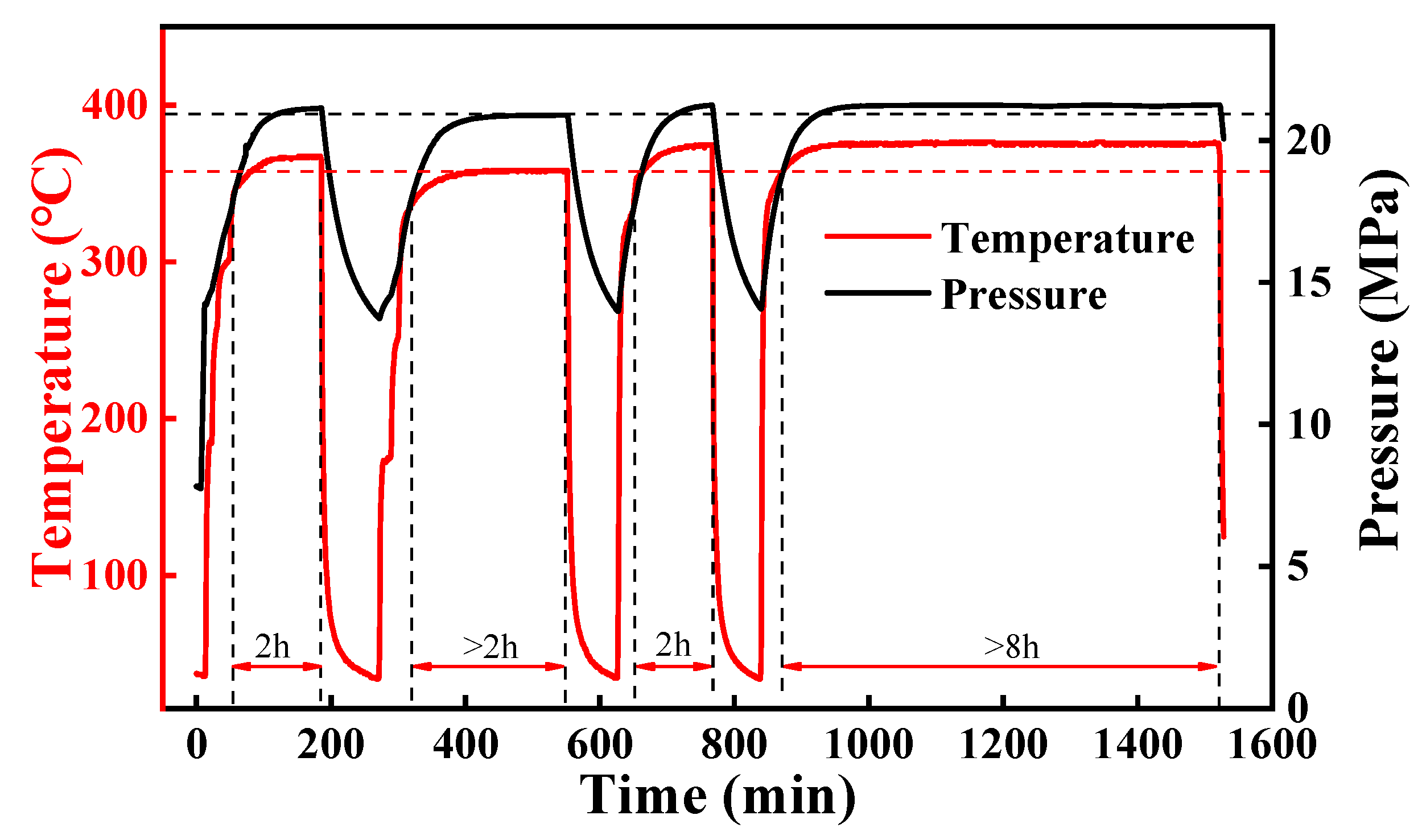
The pressure variation of the 511 direct-connect threaded connection under high-temperature and high-pressure cyclic testing conditions is demonstrated in
Figure 5. During the initial and secondary heating stages, the internal tubing pressure exhibited a slight decrease of less than 2%, gradually stabilizing during the stabilization phase with no significant pressure loss observed. However, after three cycles of thermal cycling, the internal pressure of the test specimens showed a persistent decline trend during stabilization phases, with a total decrease exceeding 5%, indicating gradual degradation of gas tightness with the increase in thermal cycles. Under 350 °C/21 MPa conditions, the synergistic effects of thermal stress and pressure fluctuations not only induced microscopic plastic deformation in the threaded connection areas but also caused gradual degradation of the serrated thread structure. The repeated expansion and contraction during thermal cycling led to reduced contact pressure between the inner and outer sealing surfaces, while high-temperature carbonization of the sealant further weakened the auxiliary sealing effect, collectively resulting in increased leakage rates. Compared to the relatively stable pressure state observed under 50 °C/21 MPa conditions, the pressure decrease at 350 °C was significantly more pronounced, demonstrating that thermal stress has a more pronounced impact on the gas tightness of the 511 direct-connect threaded connections.
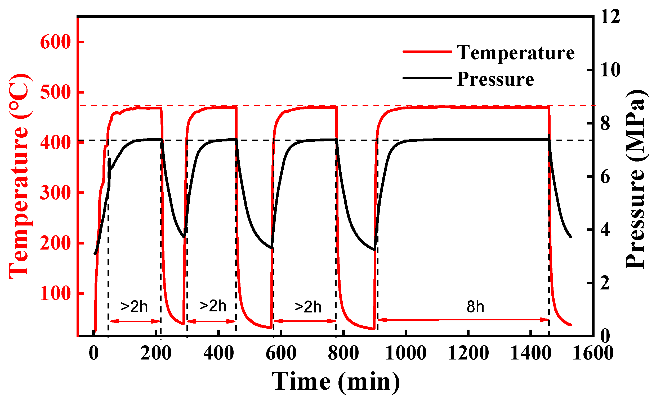
Figure 6 illustrates the dynamic temperature and pressure change curves of the 511 direct-connect threaded connection under high-temperature, low-pressure testing conditions. The pressure fluctuations observed before 400 min in the curve were due to gas injection into the casing prior to the experiment for leak integrity verification. The specific low-pressure condition in this experiment was set to 2.8 MPa. As shown in
Figure 6, during the first two heating cycles, the temperature and pressure states within the casing remained stable with no significant pressure drop. However, during the third heating cycle and subsequent stabilization phase, a malfunction of the temperature sensor probe caused the internal device temperature to reach approximately 575 °C, with the pressure rising to a peak exceeding 5.8 MPa compared to the first and second experiments. Despite this, calculations based on the leakage rate
S indicated that the 511 direct-connect threaded connections maintained good gas-tight performance under high-temperature, low-pressure conditions.
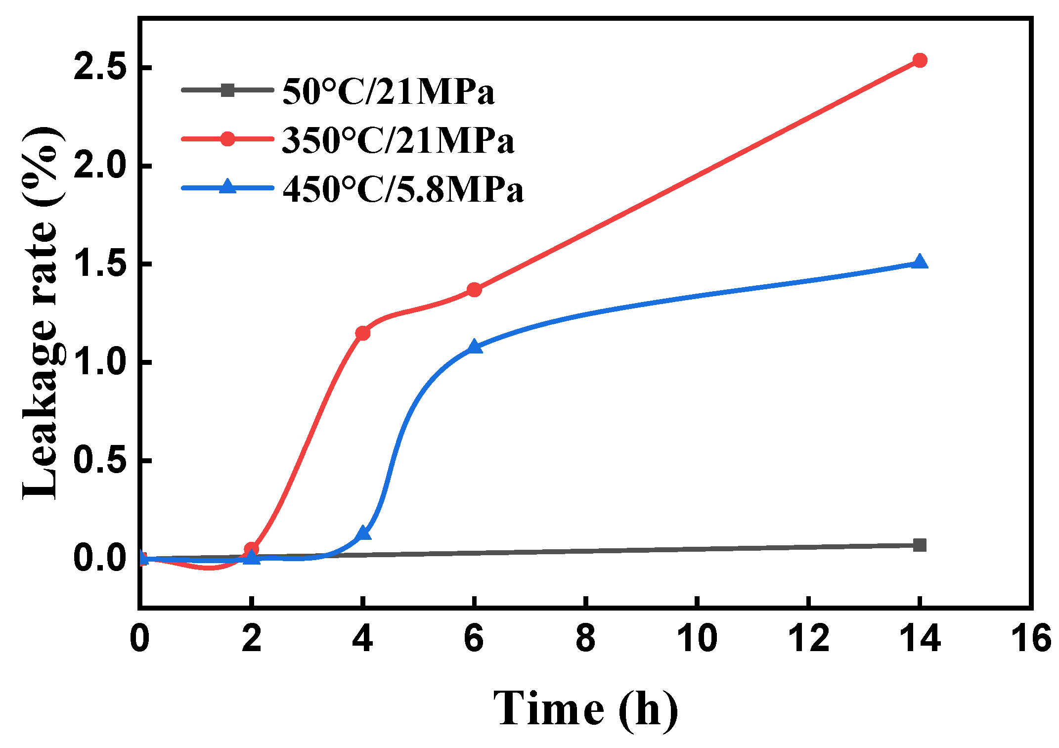
Figure 7 presents the gas-tightness leakage rate results of the 511 direct-connect threaded connection under three temperature–pressure conditions, with the
x-axis representing cumulative testing time. Under the 50 °C/21 MPa condition, the leakage rate showed negative values during the first two cycles (2 h and 4 h), reaching 0.42% at the third cycle (6 h), before decreasing to 0.07% after an 8 h stabilization period. This fluctuation originated from temperature instability caused by insufficient precision of heating equipment at lower temperatures, leading to incomplete thermal equilibrium. Thus, the 2 h cycle data was deemed unreliable, and the final 0.07% result after 8 h was adopted.
For oil casing connections under downhole conditions, the industry generally accepts a leakage rate limit of less than 1 × 10⁻³ cm3/s as specified in API RP 5C5/ISO 13679 standards, which serves as a critical benchmark for judging sealing validity in this study.
At this benchmark, the 511 direct-connect threaded connection showed varying performance across different temperature–pressure conditions: under the 350 °C/21 MPa (high-temperature/high-pressure) and 450 °C/7 MPa (high-temperature/low-pressure) conditions, the leakage rate of the 511 direct-connect threaded connection increased progressively with testing time, with higher leakage rates observed under high-temperature/high-pressure conditions compared to high-temperature/low-pressure. After an 8 h stabilization period, the leakage rates were 0.07% (50 °C/21 MPa), 2.54% (350 °C/21 MPa), and 1.51% (450 °C/7 MPa). These results indicate that the 511 direct-connect threaded connection maintains acceptable gas tightness under single extreme conditions (high-temperature or pressure) but exhibits reduced stability under combined high-temperature/high-pressure conditions.
3.2. High-Temperature Gas-Tightness Analysis of TPG2 Thread
The TP-G2 premium connection was developed by Vallourec, a French company, and is designed to meet high demands for connection strength and gas tightness under harsh well conditions.
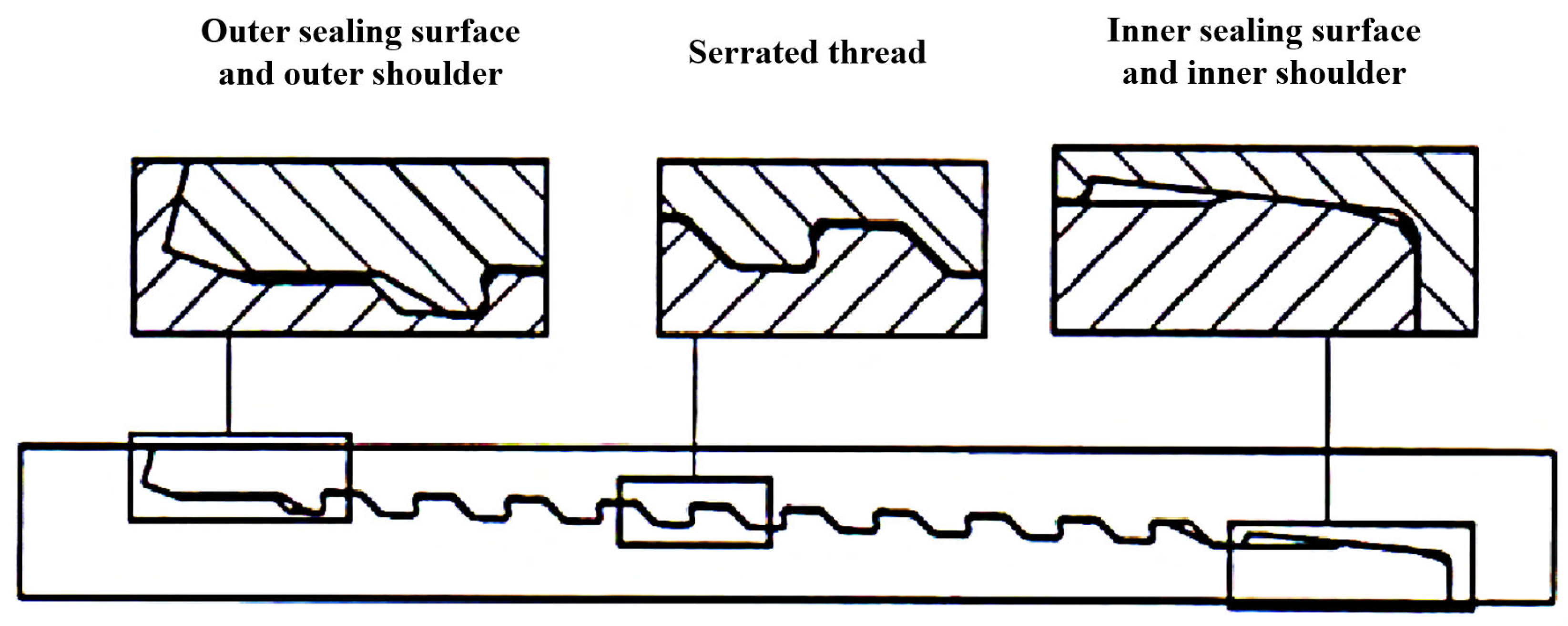
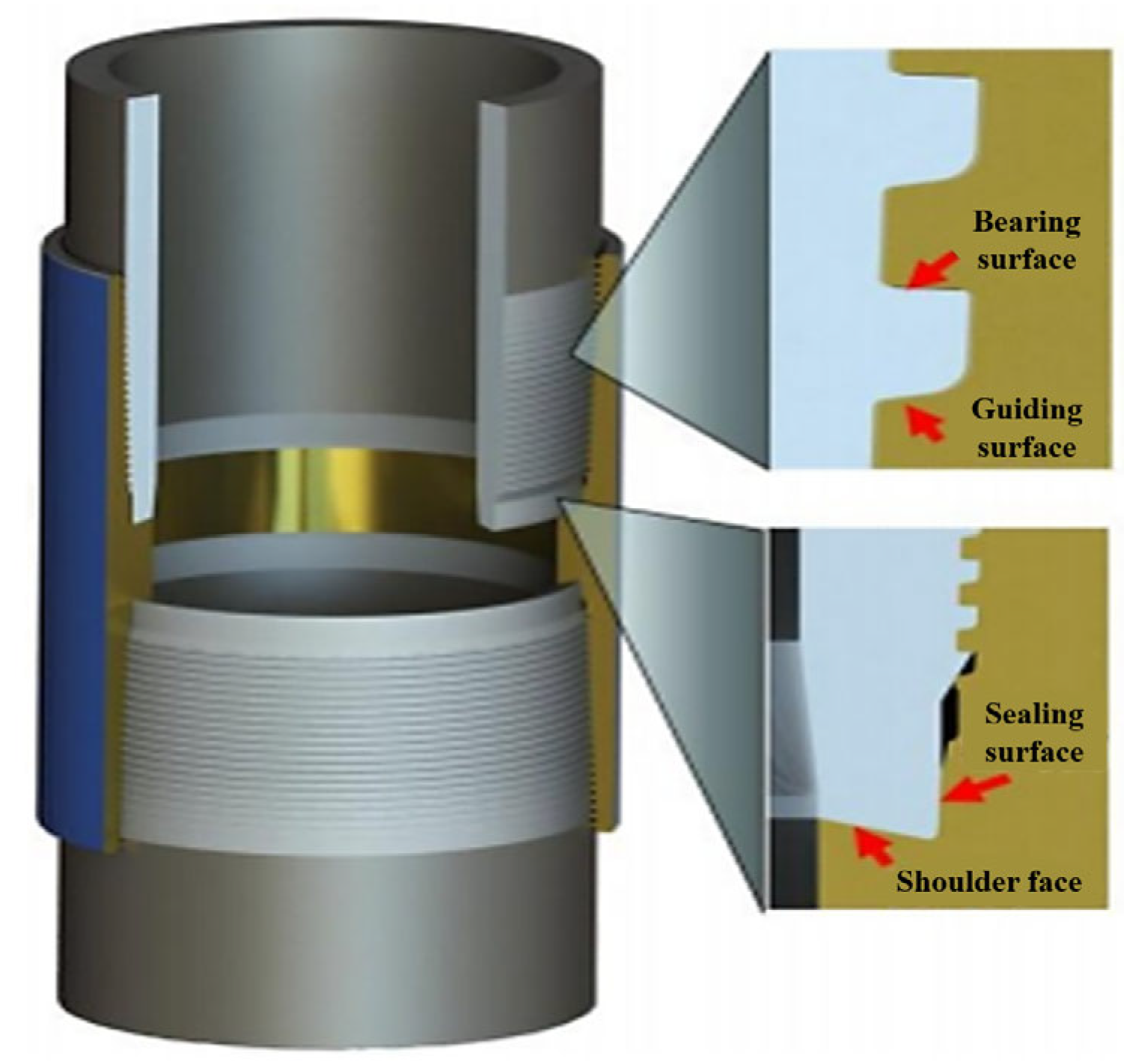
Figure 8 illustrates the schematic diagram and cross-sectional view of the TP-G2 gas-tight threaded connection.
TP-G2 connection is a high-performance threaded connection, featuring key characteristics: a barbed thread design that significantly enhances tensile strength and resistance to internal and external pressure, effectively preventing casing thread loosening and ensuring connection stability and reliability; a sealing area utilizing a metal-to-metal seal structure that achieves precise sealing through elastic interference fit, maintaining stable sealing effects under harsh well conditions and improving sealing reliability and safety; a −15° torque shoulder design that increases torque capacity, adapting to high-torque drilling environments; and an internal flush bore design facilitates installation and disassembly, reduces fluid flow resistance, and enhances transmission efficiency. This study selected the TP-G2 threaded connection due to its unique designs, such as the barbed thread design, multi-stage sealing structure, and negative angle torque shoulder, enabling it to demonstrate high connection strength, excellent gas tightness, galling resistance, and high torque capacity in complex downhole environments, providing reliable assurance for the safe and efficient extraction of oil and gas wells.
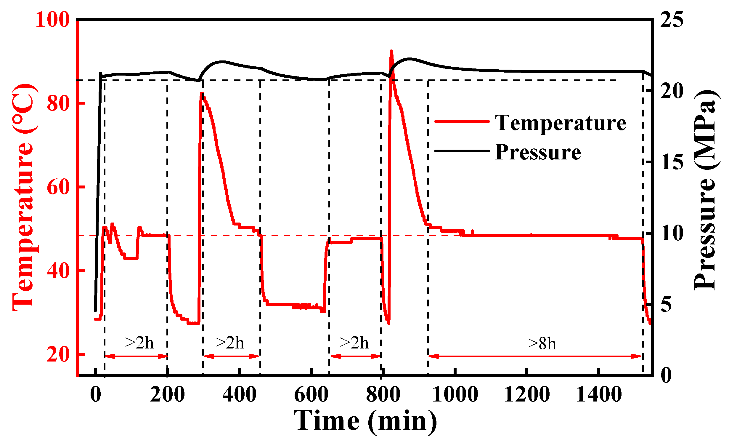
Figure 9 shows the dynamic variation curves of temperature and pressure for the TP-G2 threaded connection under low-temperature and high-pressure test conditions of 50 °C and 21 MPa. The temperature curve indicates significant fluctuations during the heating phase, with instantaneous peaks exceeding 80 °C. As the heating time increases, the temperature gradually stabilizes at 50 °C, and the internal pressure of the casing stabilizes simultaneously with no significant fluctuations. In multiple cycle experiments, the pressure values tend to be consistent, indicating that the TP-G2 threaded connection has good gas tightness in low-temperature and high-pressure environments.
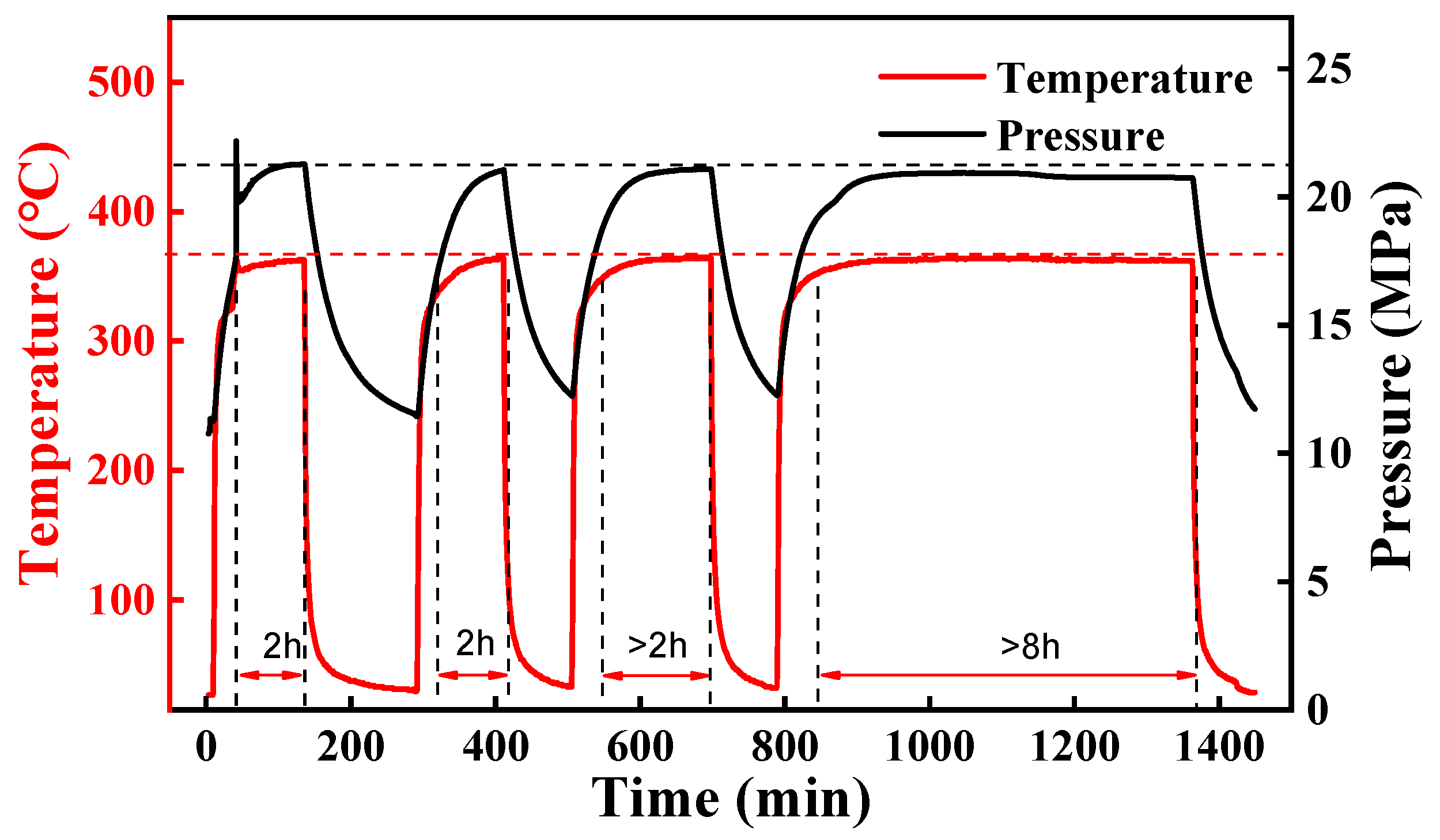
Figure 10 shows the dynamic variation curves of temperature and pressure for the TP-G2 threaded connection under test conditions of 350 °C and 21 MPa. As can be seen from
Figure 10, under high-temperature and high-pressure conditions, the internal pressure of the casing responds well to temperature changes, and during the temperature-stable holding period, the pressure did not show a significant downward trend. This indicates that the TP-G2 threaded connection exhibits good stability in high-temperature and high-pressure environments.
Figure 11 shows the temperature and pressure variations of the TP-G2 threaded connection under test conditions of 450 °C and 7.4 MPa. From
Figure 11, it can be observed that during three heating cycles, the temperature stably reached and remained at 450 °C, indicating that the heating system operated stably and accurately simulated the high-temperature environment. Meanwhile, the pressure curve shows that during each heating process, the pressure gradually increased and stabilized, with no significant fluctuations or anomalies, demonstrating that the TP-G2 threaded connection has good gas tightness and stability in high-temperature environments.
The barb-thread design of TPG2 enhances mechanical interlock through its asymmetric thread profile (30° load flank and 15° stab flank). During thermal cycling, as temperature rises, the casing material expands, and the barb structure generates radial clamping force that resists thread loosening caused by thermal expansion. When cooled, the barb’s undercut geometry prevents axial retraction between male and female threads, minimizing micro-gaps at the thread interface.
Under the high-temperature condition of 450 °C, even after multiple cycles of heating and holding, the pressure did not show a significant downward trend, indicating that the gas tightness did not degrade significantly due to high-temperature thermal cycling. Specifically, during the three heating cycles, the pressure variation curve consistently synchronized with the temperature changes, with no obvious leakage phenomena. This indicates that the sealing structure of the TP-G2 threaded connection can effectively resist the effects of thermal stress under high-temperature and low-pressure conditions, maintaining good sealing effectiveness. This demonstrates the excellent sealing and stability of the TP-G2 threaded connection in high-temperature and low-pressure environments.
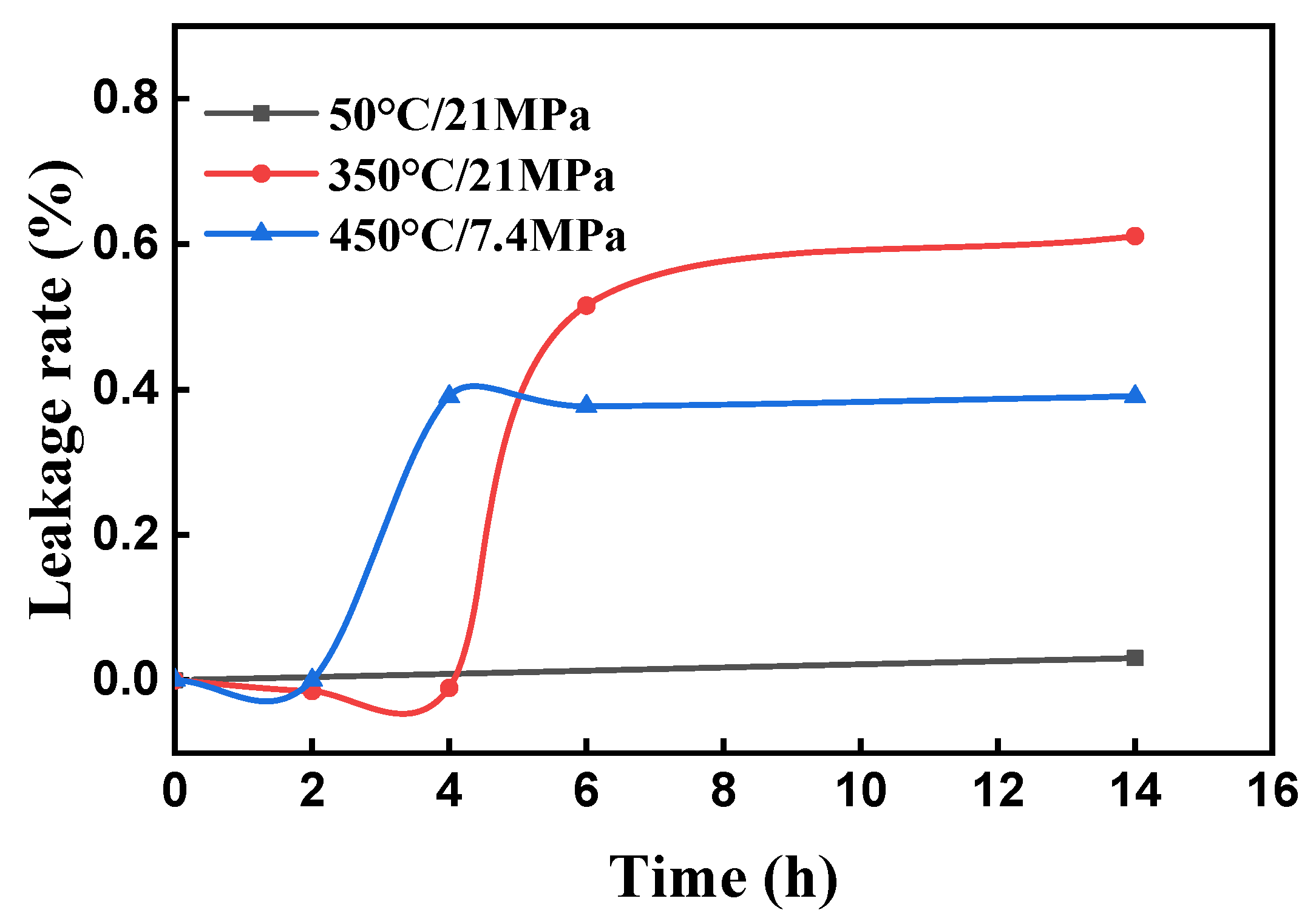
Figure 12 shows the leakage rate results from three sets of gas-tightness tests for the TP-G2 threaded connection, with the horizontal axis representing cumulative test time. It can be seen that at 50 °C and 21 MPa, the leakage rates of the specimens all exhibited negative values, which is related to significant temperature fluctuations during the test, causing the system not to reach equilibrium during the test period. After an 8 h holding period, the leakage rate of the connection remained negative (−0.43%). In the two sets of tests at 350 °C/21 MPa and 450 °C/7.4 MPa, the leakage rates showed an increase with the increase in test time, with significant increases observed at 6 h and 4 h, respectively, and then stabilized. After an 8 h holding period, the leakage rate for the 350 °C/21 MPa test was 0.61%, and that for the 450 °C/7.4 MPa test was 0.39%.
3.3. High-Temperature Gas-Tightness Analysis of BGT2 Thread
BGT2 special coupling (
Figure 13), as a domestically produced special gas-sealing thread for oil casing developed by China’s Baosteel, employs a modified buttress thread design, optimizing the load flank angle and stab flank angle to enhance connection efficiency, ensuring the connection tensile strength exceeds the pipe body strength, and improving thread integrity through interference control. Its core sealing structure is a radial metal-to-metal interference seal, achieving superior gas tightness and leak resistance, reaching the pipe body yield pressure, while incorporating a torque shoulder design for precise control of make-up torque, overcoming API connection limitations, providing auxiliary sealing to enhance anti-galling property and over-torque resistance The internal flush design enables smooth transition, eliminating oil and gas turbulence, increasing corrosion resistance, and widely adapting to deep wells, ultra-deep wells, high-pressure oil and gas wells, and environments with corrosive media such as CO
2 and H
2S. This study utilizes the BGT2 thread to assess its gas-tightness performance as a domestic representative under high-temperature and high-pressure conditions through multi-temperature and pressure cycling tests, comparing it with the 511 straight connection thread and TPG2 thread and quantifying sealing stability to provide empirical data for optimization design of domestic special threads (e.g., strengthening of sealing mechanisms).
Figure 14 shows a photo of the BGT2 threaded connection specimen after testing. After prolonged high-temperature treatment, the surface of the outer pipe component of the heater formed black coke residue, and the sealant at the connection underwent carbonization at high-temperature. During the 350 °C test process of this specimen, the sealant at the connection melted.
The following details the experimental results of the gas tightness of the BGT2 threaded connection under various temperature and pressure conditions.
Figure 15 shows the temperature and pressure variations of the BGT2 threaded connection under the test conditions of 50 °C and 21 MPa. From the figure, it can be observed that, similar to the previous two sets of low-temperature and high-pressure tests, under the 50 °C temperature condition, the temperature controller fluctuates significantly during the heating process, and the pressure gradually increases and stabilizes during each heating cycle, indicating that the system operates stably under low-temperature and high-pressure conditions. The pressure curve shows that the pressure variation curve is highly synchronized with the temperature variation curve during the three heating cycles, indicating that the BGT2 threaded connection has good gas tightness under low-temperature and high-pressure conditions, with no significant leakage observed. During the holding stage, there is no obvious downward trend in pressure, indicating that the gas tightness can maintain stability for a longer period under low-temperature conditions. This demonstrates that under the operating conditions of 50 °C and 21 MPa, the BGT2 threaded connection can provide reliable gas tightness, meeting the requirements for use in low-temperature and high-pressure environments.
Figure 16 shows the temperature and pressure changes of the BGT2 threaded connection under the test conditions of 350 °C and 21 MPa. During three heating cycles, the specimen temperature stably reached and remained at 350 °C, and the pressure synchronously increased and stabilized during each heating process without significant fluctuations or anomalies. However, after multiple cycles of heating and holding, during the holding stage, the pressure showed a significant downward trend, indicating that the gas tightness significantly degraded due to high-temperature thermal cycling. The temperature–pressure curve indicates that the sealing structure of the BGT2 threaded connection cannot effectively resist the effects of thermal stress under high-temperature and high-pressure conditions, demonstrating that the BGT2 threaded connection has insufficient stability under dual extreme conditions of high-temperature and high pressure.
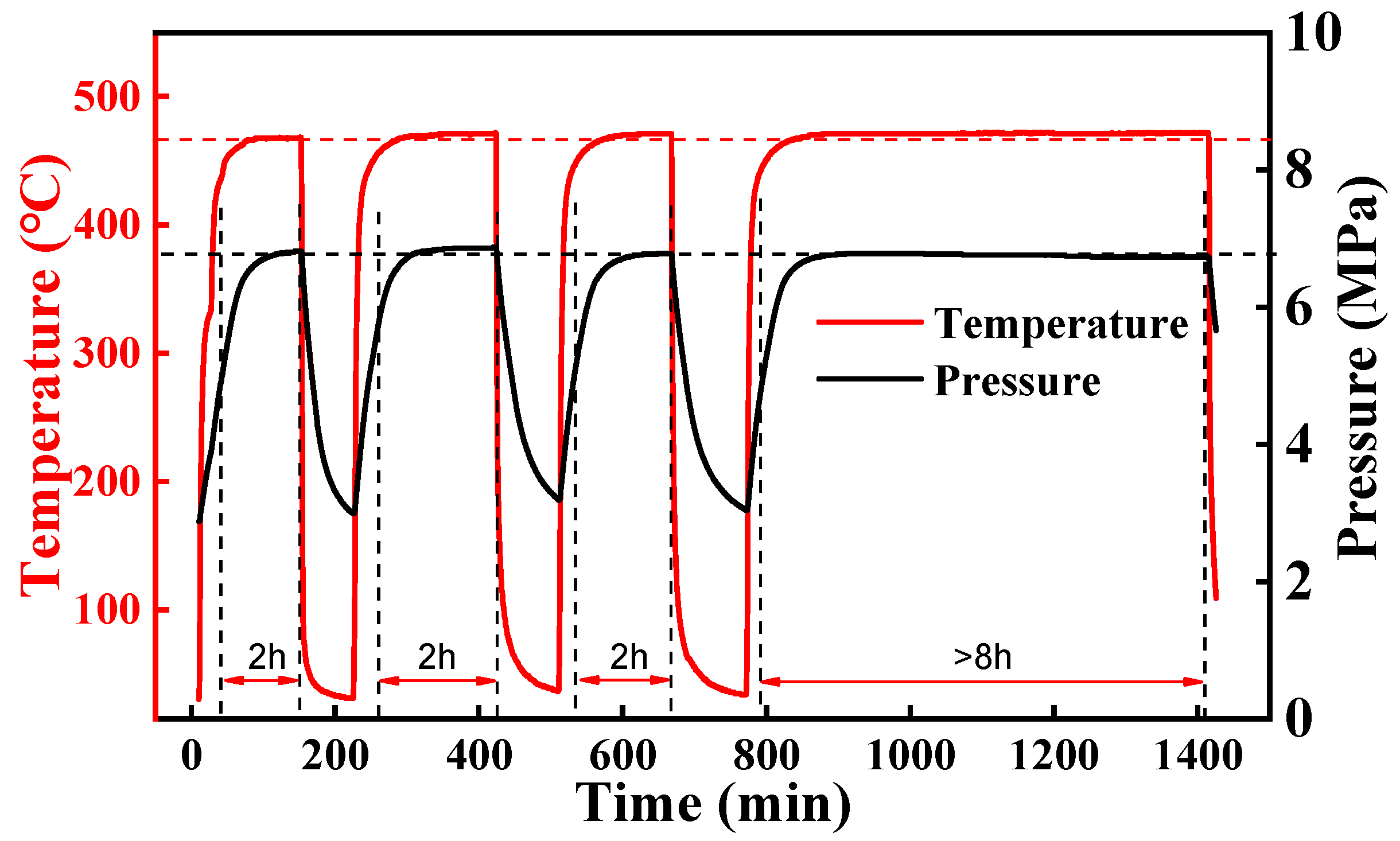
Figure 17 illustrates the temperature and pressure variations of the BGT2 threaded connection under test conditions of 450 °C and 6.8 MPa. It can be observed from the figure that during three heating cycles, the temperature stably reached and remained at 450 °C, and the pressure gradually increased and stabilized during each heating process without significant fluctuations or anomalies. Under the high-temperature condition of 450 °C, after multiple cycles of heating and insulation, the pressure did not show a significant downward trend, indicating that the gas tightness did not significantly degrade due to high-temperature thermal cycling. Specifically, in the three heating cycles, the pressure change curve consistently synchronized with the temperature change, with no apparent leakage phenomena. This demonstrates that the sealing structure of the BGT2 threaded connection can effectively resist the influence of thermal stress under high-temperature and low-pressure conditions, maintaining good sealing effectiveness. The synchronous changes in temperature and pressure further verify the structural integrity and reliability of the connection in high-temperature environments. Even at 450 °C, the connection can maintain stable gas tightness with no significant leakage risk, demonstrating the excellent sealing and stability of the BGT2 threaded connection in high-temperature and low-pressure environments.
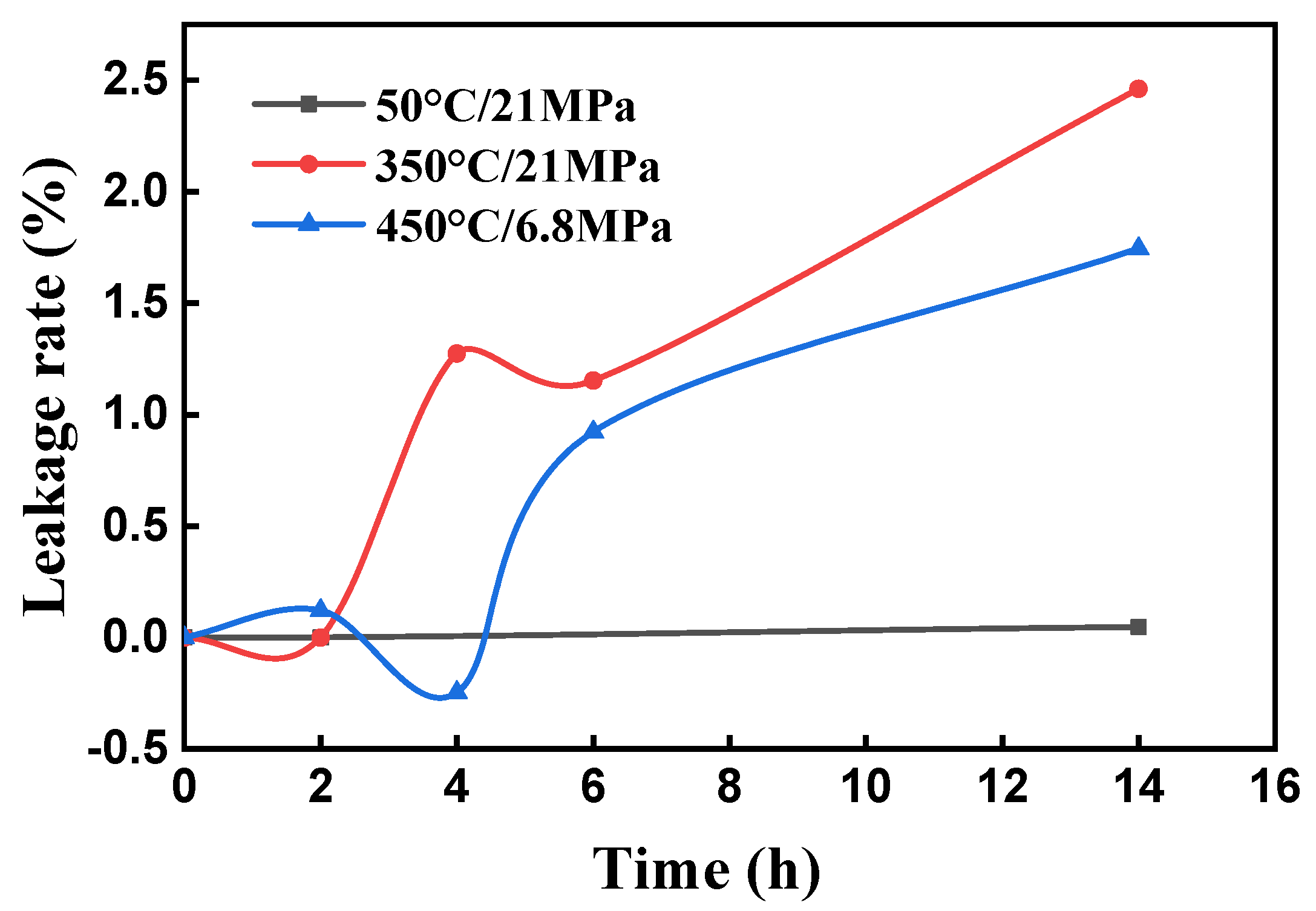
Figure 18 shows the leakage rate variation of the BGT2 threaded connection under different test conditions. From the figure, it can be seen that in the low-temperature test, the leakage rate exhibited negative values. This corresponds to the fluctuations in the temperature curve during the second cycle and at 8 h of holding in
Figure 18, indicating that temperature instability affected the test results. This verifies that during low-temperature testing, temperature fluctuations may lead to unstable test results; therefore, in subsequent low-temperature tests, it is necessary to extend the test time to ensure system stability. Under both high-temperature conditions, the leakage rate showed fluctuations with the increase in test time and ultimately exhibited an increasing trend. The leakage rate under 350 °C/21 MPa conditions was significantly higher than that under 450 °C/6.8 MPa conditions at all stages, which is mainly due to insufficient resistance of its modified buttress thread to thermal stress. Additionally, the torque shoulder design cannot fully offset the stress concentration caused by temperature–pressure synergy, leading to gradual sealing degradation. After 8 h of holding, the leakage rate for the 350 °C/21 MPa test was 2.46%, while for the 450 °C/6.8 MPa test it was 1.74%. This indicates that the BGT2 threaded connection has poor gas tightness in high-temperature and high-pressure environments.
The stable leakage rate at low temperature and high pressure (50 °C/21 MPa) is attributed to minimal thermal deformation of the connections. At 50 °C, the material (L80-13Cr) remains in the elastic range, and the 21 MPa pressure maintains tight contact between sealing surfaces, preventing the formation of new micro-gaps—thus, leakage rate fluctuations are within 0.2%/h. In contrast, at high temperature and high pressure (350 °C/21 MPa) and high temperature and low pressure (450 °C/6.8 MPa), the initial rapid increase in leakage rate is caused by thermal expansion-induced micro-gap formation at thread roots and seal interfaces. As the experiment proceeds, the materials reach thermal equilibrium, and the micro-gaps stabilize, leading to a constant leakage rate.
4. Conclusions
This study comprehensively analyzed the gas tightness of the 511 integral connection thread, TPG2 thread, and BGT2 thread in multi-temperature–pressure cycles (50 °C/21 MPa, 350 °C/21 MPa, 450 °C/low pressure). Using leakage rate calculations, it revealed the variation in regularity of connection gas tightness and assessed the stability and durability of each connection. The results show that high-temperature and high-pressure conditions most significantly impact gas tightness. Key conclusions are as follows:
- (1)
At 50 °C/21 MPa (low temperature and high pressure), all connections showed good sealing. But temperature fluctuations destabilized test data, causing negative leakage rates. So, longer testing is needed to ensure system equilibrium.
- (2)
Under the 350 °C/21 MPa high-temperature and high-pressure conditions, the leakage rate reached the highest level (TPG2: 0.61%, 511: 2.54%, BGT2: 2.46%), indicating that the synergistic effect of high-temperature and high pressure exerts the most significant adverse impact on gas tightness, potentially leading to seal failure.
- (3)
Under high-temperature and high-pressure conditions, TPG2 threads performed best, with the lowest leakage rate (0.61%) and a trend toward equilibrium. This shows excellent stability and durability, attributed to the hook-shaped threads and multi-stage sealing structure.
- (4)
Under high-temperature/high-pressure conditions, the leakage rates of the 511 direct-connect threaded and BGT2 threaded connections are comparable (approximately 2.5%). However, these leakage rates increase over testing time, indicating inferior performance compared to the TP-G2 and highlighting risks of sealing degradation.
- (5)
At 450 °C/low pressure (high-temperature and low-pressure conditions), TPG2 and BGT2 connections had good sealing (leakage rates of 0.39% and 1.74%, respectively), while 511 integral threads performed poorly (leakage rate of 1.51%). This indicates TPG2 has advantages in extremely high-temperature working conditions.
Based on the findings, the following practical recommendations are proposed:
- (1)
Thread geometry design: Prioritize barb-type thread profiles (e.g., TPG2′s 30° load flank and 15° stab flank) and multi-stage sealing structures in high-temperature/high-pressure environments, as they effectively resist thermal expansion-induced loosening and maintain contact pressure.
- (2)
Torque settings: Optimize torque shoulder angles (e.g., TPG2′s −15° design) to absorb thermal stress and calibrate make-up torque for BGT2 to enhance stability under HTHP synergy conditions.
- (3)
Application scenarios: TPG2 is recommended for ultra-deep HTHP wells and heavy oil thermal recovery wells, while BGT2 can be used in high-temperature, low-pressure environments with modified sealants.
Our findings on temperature–pressure impacts on casing thread gas tightness align with broader industry research trends, where high-stress thermal–hydraulic environments are consistently shown to challenge seal integrity. Many prior studies highlight that special threaded connections outperform conventional designs in extreme conditions, consistent with our TPG2-favorable results. However, unlike general assessments in the existing literature, our multi-cycle testing (50 °C/21 MPa → 350 °C/21 MPa → 450 °C/7 MPa) quantifies degradation rates across connection types, providing finer-grained insights into performance decay under cyclic loading. Where most research focuses on single-variable effects (e.g., pure temperature or pressure), our work captures their synergistic influence, reinforcing the need for integrated design considerations in complex reservoirs.
