Article

Enhanced Interior PMSM Design for Electric Vehicles Using Ship-Shaped Notching and Advanced Optimization Algorithms

1
Department of Electrical Engineering, Iran University of Science & Technology, Tehran 16846-13114, Iran
2
Department of Electrical Engineering, Shahid Beheshti University, Tehran 19839-69411, Iran
3
School of Engineering, Newcastle University, Newcastle Upon Tyne NE1 7RU, UK
*
Author to whom correspondence should be addressed.
Energies 2025, 18(17), 4527; https://doi.org/10.3390/en18174527
Submission received: 23 July 2025 / Revised: 18 August 2025 / Accepted: 22 August 2025 / Published: 26 August 2025

Abstract

This paper compares two types of interior permanent magnet synchronous motors (IPMSMs) to determine the most effective arrangement for electric vehicle (EV) applications. The comparison is based on torque ripple, power, efficiency, and mechanical objectives. The study introduces a novel technique that optimizes notching parameters in a selected motor topology by inserting a ship-shaped notch into the bridge area between double U-shaped layers. In addition, this study presents two comprehensive approaches of robust combinatorial optimization that are used in machines for the first time. In the first approach, modeling is performed to identify important variables using Pearson Correlation and the mathematical model of the Anisotropic Kriging model from the Surrogate model. Then, in the second approach, the proposed algorithm, Multi-Objective Genetics Algorithm (MOGA), and Surrogate Quadratic Programming (SQP) are combined and implemented on the Anisotropic Kriging model to choose a robust model with minimum error. The algorithm is then verified with FEM results and compared with other conventional optimization algorithms, such as the Genetics Algorithm (GA) and the Particle Swarm Optimization algorithm (PSO). The motor characteristics are analyzed using the Finite Element Method (FEM) and global map analysis to optimize the performance of the IPMSM for EV applications. A comparative study shows that the enhanced PMSM developed through the optimization process demonstrates superior performance indices for EVs.

1. Introduction

The growing demand for transportation and concern about the environmental impact of fossil fuel combustion have led to a surge in EV production. Electric motors (EMs) in these vehicles offer advantages over internal combustion engines, such as higher efficiency and a longer, consistent power range [1,2]. To meet the needs of EVs, EMs must have specific characteristics, including high power and torque density, low torque ripple, and a wide power range. Reliability and fault tolerance are also crucial for ensuring passenger safety in EVs [3,4,5].
In recent years, there has been a lot of research focused on developing and designing EMs for EVs to improve their overall performance. Permanent magnet synchronous motors (PMSPMs) are the preferred choice for EV applications [6,7,8]. Among PMSMs, IPMSMs are favored because they offer a wide constant power range, superior high-speed performance, and reluctance torque compared to surface-mounted permanent magnet synchronous motors (SMPMSMs) [9,10].
Some studies have presented methods for optimizing the design of IPMSMs to improve torque output, mechanical characteristics, and reliability. The placement of the flux barrier is crucial in optimizing IPMSMs, as presented in a study where optimizing the flux barrier angle within the motor design resulted in improved electrical and mechanical behavior [11]. The growing importance of IPMSMs in EVs has led to improvements in various rotor designs. While there have been few comprehensive studies on various types of IPMSM rotors, it has been suggested that V-shaped, U-shaped, and double-layer PM rotors provide optimal torque output [12].
Reference [13] presents a method for obtaining the optimal design of a V-shaped IPMSM using continuum-sensitivity. This method significantly reduces computation time, especially with numerous design variables. The standard parameters were optimized using the orthogonal experimental method (OEM), while the significant parameters were optimized using a combination of multi-island genetic algorithm (MIGA) and radial basis function neural networks (RBF-NNs) to reduce torque ripple of the IPMSM [14]. To improve the torque performance of high-speed IPMSM electromagnetics, a Surrogate model is used for optimization [15].
First, a design of experiment (DOE) is conducted, followed by fitting multiple Surrogate models. The models with the lowest error are selected using error evaluation indexes for optimization. The non-dominated sorting genetic algorithm (NSGA) is then used to obtain the optimal solution [16,17]. The NSGA is a popular optimization method that uses the elitist strategy with the crowding distance operator to preserve diversity and the non-dominated sorting operator to select the Pareto dominant solutions. In [18], the IPMSM is optimized for multiple objectives and multi-load points using a global response surface method (GRSM) to minimize torque ripple and maximize average torque. Hybrid optimization algorithms, such as DOE, Sensitivity Analysis (SA), Response Surface Method (RSM), and PSO, are utilized to determine the rotor design parameters that maximize the output torque of the PMSM across three different load conditions [11]
Proposal [19] introduces a multi-objective layered optimization method based on parameter hierarchical design combined with the Taguchi method and RSM. An improved iterative Taguchi method has been proposed in [20], involving narrowing optimization ranges to find optimal structural parameters efficiently. Its superiority is verified by comparing it with the conventional Taguchi method.
The review of the research performed on multi-objective optimization techniques is listed in Table 1. In this paper, a novel technique that optimizes two comprehensive approaches of robust combinatorial optimization is used in a U-shaped IPMSM. According to Table 1, the novelties of this paper are the following:
  • Most of the combined optimization methods are on V-shaped PMs. Therefore, compound optimization on U-shaped magnets is necessary for new studies;
  • From the Surrogate model with the approval of the NSGA, only one case has been implemented on the V-shaped PM. Also, this method is performed on a ship-shaped notch into the bridge area between double U-shaped layers for the first time in this study;
  • In this study, we used an optimization approach with a parameter optimization hierarchy, implementing DOE, Optimal Latin Hypercube Sampling Designs (OLHSD), and Pearson Correlation for a ship-shaped notch double U-shaped layers machine. Then, we used the Surrogate model’s SA and Anisotropic Kriging model to finalize the mathematical model of the parameters;
  • The combined GA and SQP algorithm is used to validate the accuracy of the final model extracted;
  • The hybrid model optimized with common algorithms such as GA and PSO is compared, and its superiority compared to other methods is determined.
Table 1. Review of multi-objective optimization techniques.
Ref.Type of MachineType of PMOptimization TechniquesFEM/Experimental
[13]IPMSMV-shapedContinuum-Sensitivity✓/✗
[14]OEM/MIGA/RBF-NN
[15]Surrogate models/NSGA✓/✓
[18]GRSM
[11,21]DOE/SA/RSM/PSO✓/✗
[22,23]Taguchi Method✓/✓
[19]Taguchi method/RSM✓/✓
[16]C-shapedNSGA
[20]U-shapedTaguchi method
To achieve the desired torque, U-shaped and V-shaped structures were designed and then compared. A notched ship-shaped is subsequently created on the rotor surface of the chosen structure to minimize torque variation. The primary objective of this research is to utilize a new optimization approach that is both precise and resilient in optimizing the selected structure. This methodology is then compared to traditional optimization methods. Furthermore, the electromagnetic performance and mechanical analysis of this optimized structure are examined. Lastly, the EM is evaluated under load under EV standards to ascertain its suitability.

2. Topologies and Features

The electromagnetic and mechanical results of the two designs under investigation are presented in Table 2. It can be inferred that the mechanical properties, such as the safety factor, performed better in the V-shaped design compared to the U-shaped design. Conversely, the electromagnetic characteristics, including the produced torque and efficiency, were better in the U-shaped design compared to the V-shaped design.
The U-shaped design is used to continue the design. IPMSMs are often designed with multiple layers to reduce higher-order spatial flux harmonics [24], reduce torque ripple [25,26], and increase salience [27]. In [28], a lot of research is presented on the performance of different layers on the behavior of the IPMSM.

A Ship-Shaped Notch Rotor for Multiple-Layered U-Shaped PMSM

Torque ripple is the result of the interaction between MMF harmonics and air-gap flux density. To minimize this, reduce or eliminate high-order harmonics by using the appropriate winding type, altering the shape of the PM pole, or enhancing the flux reluctance path. Conversely, in structures with a prominent rotor, torque ripple arises from the interaction between the stator current’s magnetic flux and the rotor permeability harmonics. In internal permanent magnet rotor topologies, the PMs are positioned in the core of the rotor. Modifying the shape of the PM pole and adjusting the direction of the flux between the poles can impact the reluctance component of the rotor.
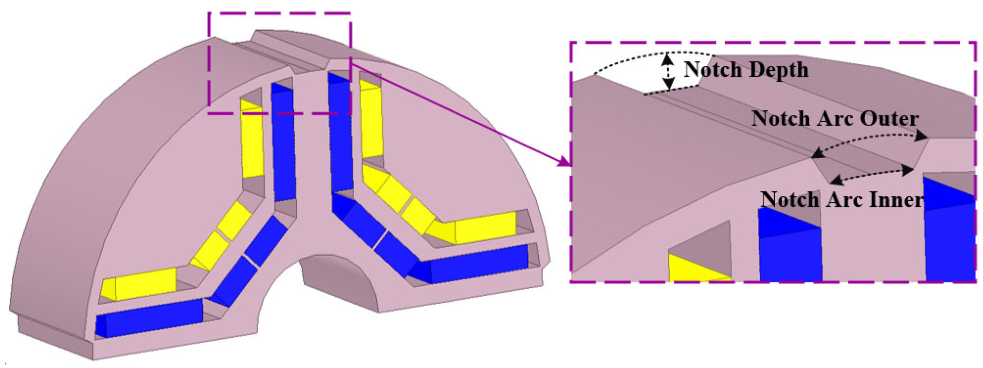
To avoid disturbing air-gap harmonics, a ship-shaped notch can be added to the rotor surface. This notch has varying indentation point radii and is positioned between the two poles, in the magnet’s bridge area. This area experiences saturated flux in the rotor. By adding an optimal notch in this location, disruptive harmonics in the air gap can be eliminated, and the reluctance path between the stator and the rotor can be modified.
This irregularly ship-shaped notch cut consists of three variables, as depicted in Figure 1. By adjusting the internal and external angles, the shape and appearance of the cut can be altered, making it easier and more precise to achieve an optimal design. The notch is not constrained by a fixed radius. Variables of the ship-shaped notch rotor are presented in Figure 2. Figure 3 displays the impact of these three variables on reducing torque ripple through one time sensitivity analysis. The external angle and notch depth have a more significant effect on torque fluctuations compared to the internal angle. Utilizing the external angle and notch depth allows for the design of various notch types. The torque ripple was calculated using the Maxwell stress method within the FEM.
This paper discusses the optimization design of a 168 kW, 4500 r/min ship-shaped notch U-shaped IPMSM and proposes a robust optimization design method in Section 3. The motor specifications are illustrated in Table 3.

3. Robust Optimization Technique

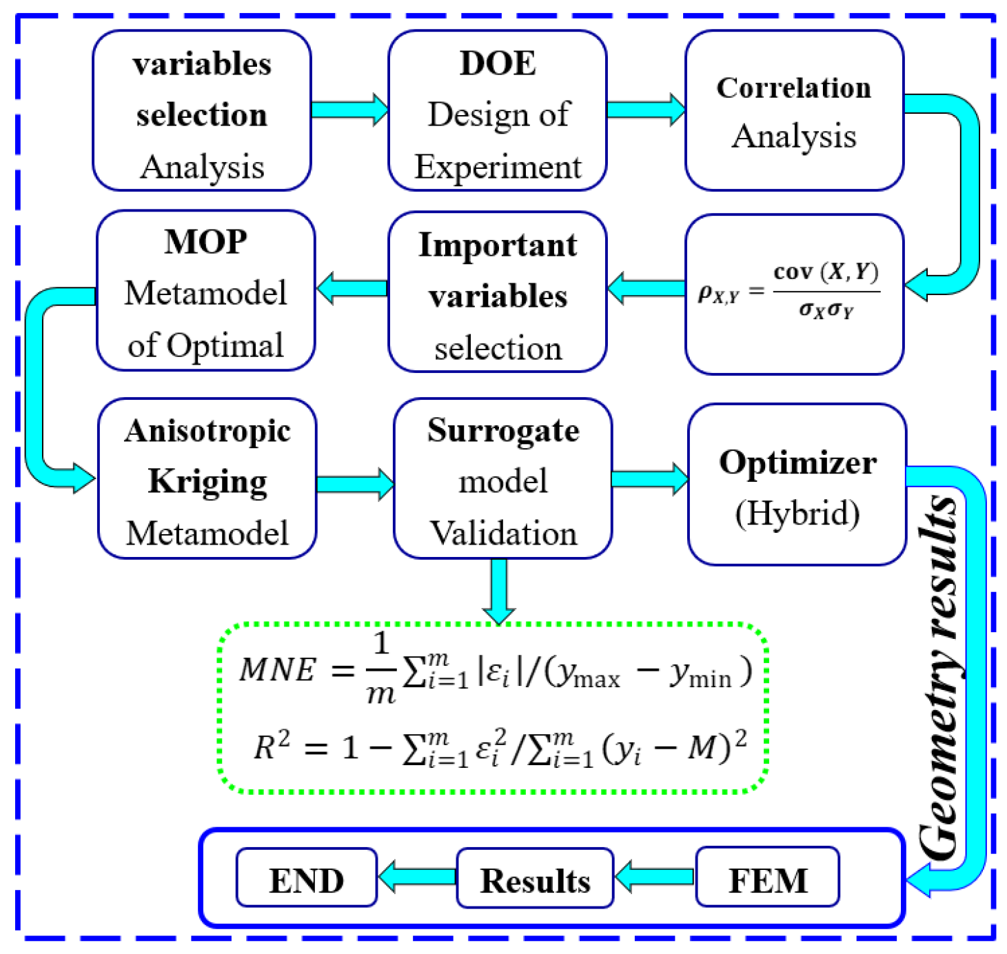
The study utilizes a robust hybrid optimization method, which is illustrated in Figure 4. The proposed hybrid optimization entails two approaches to identify important variables and select a robust model with minimal error. The provided flowchart will guide you through nine steps for finding and achieving the objectives.
i: The first approach entails identifying important variables:
  • Step 1: optimizing the selection of the design DOE using the OLHSD;
  • Step 2: along with Correlation analysis, the Pearson Correlation method is selected among its types, including Spearman Correlation, Pearson and Partial Correlation, and Partial Correlation;
  • Step 3: the optimization objectives are evaluated through sensitivity analysis. To streamline the optimization process and reduce the number of equations involving two geometric variables, we remove all correlation coefficients that have low values with the objective functions;
  • Step 4: geometric variables are implemented on the machine with a notch;
  • Step 5: selecting two methods from the Surrogate model includes the Anisotropic Kriging model, kriging model, response surface, and Artificial neural network;
  • Step 6: investigating two methods of the Surrogate model: Anisotropic Kriging and Kriging on MEN and R2, then confirming Anisotropic Kriging with FEM.
ii: The second approach aims to select a strong model with minimum error:
  • Step 7: the final structure is optimized using a combination of GA and SQP algorithms for multi-objective optimization;
  • Step 8: comparison of the proposed algorithm with GA and PSO algorithms;
  • Step 9: validation of the proposed algorithm with FEM results.

3.1. DOE and Correlation Analysis

The DOE is created using OLHSD designs to gain maximum design insight with minimal FEA simulation. It can efficiently and optimally cover the design space. In the next step, the optimization is analyzed with correlation analysis. Correlation is a measure of the linear relationship between two variables, with a value between −1 and 1. If the correlation is 1, the two variables are strongly positively correlated, and all values lie on a straight line with a positive slope. If the correlation is 0, the variables are uncorrelated, meaning they are linearly unrelated. If the correlation is −1, the two variables are completely negatively correlated and all values lie on a straight line with a negative slope. The following equation shows the correlation equation between x and y, as follows:
r = N x y ( x ) ( y ) N x 2 ( x ) 2 N y 2 ( y ) 2
where the N is the number of pairs of values. x y , x , y , x 2 , and y 2 are the sum of the products of paired values, Sum of x values, sum of rakes, sum of squared x values, and sum of squared y values, respectively.
The Pearson Correlation analysis method is used in this optimization process. It is implemented as
ρ X , Y = c o v ( X , Y ) σ X σ Y
where c o v stands for covariance, σ X represents the standard deviation of X, and σ Y represents the standard deviation of Y. (2) can be expanded as
c o v ( X , Y ) = E X μ X Y μ Y
ρ X , Y = E X μ X Y μ Y σ X σ Y
where E stands for the expected value, and μ X , and μ Y represent the mean of X and Y, respectively.
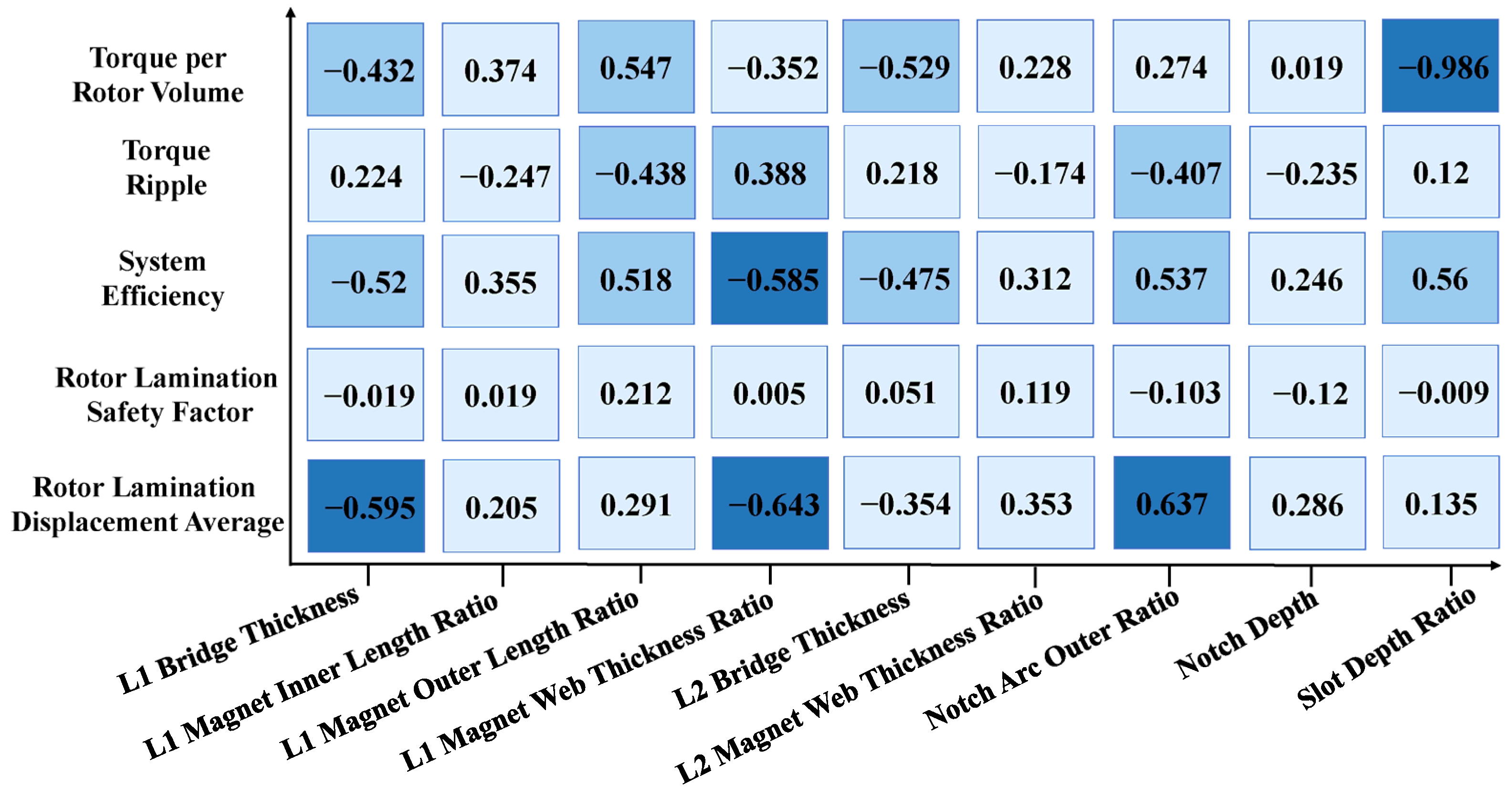
The DOE has been used to examine the correlation between the variables of the optimization objective functions. These functions include torque per rotor volume ( T v ), torque ripple ( T r i ), efficiency ( η ), and rotor lamination safety factor ( L s f ) with a rotor lamination displacement average ( L d a v ). To check the correlation, the influential geometrical variables, which were already checked to some extent through sensitivity analysis, have been used in the U-shaped IPMSM along with the dimensions of the cut ship-shape design.
The correlation results between variables and functions are displayed in Figure 5. For this study, a correlation coefficient ranging from 0 to 0.4 indicates low correlation, 0.4 to 0.6 suggests a medium correlation, and anything from 0.6 to 1 represents a high correlation. To streamline the optimization process and minimize the number of equations for two geometric variables, any correlation coefficients falling within the low range are disregarded. Additionally, to enhance the model’s reliability and address geometric errors, most variables susceptible to geometric errors are redefined as
L 1   M a g n e t   O u t e r   L e n g t h M i n i m u m M a x i m u m M i n i m u m
L 1   M a g n e t   W e b   T h i c k n e s s M i n i m u m M a x i m u m M i n i m u m
S l o t   D e p t h S t a t o r   L a m i n a t i o n   T h i c k n e s s

3.2. The Surrogate Model

The Surrogate model is a functional relationship between the design variable and the response and guarantees low computational cost, good accuracy, and highly reliable performance. At this stage, Anisotropic Kriging modeling is utilized due to its superior accuracy compared to the RSM and Kriging method and its lower complexity compared to the artificial neural network [25].
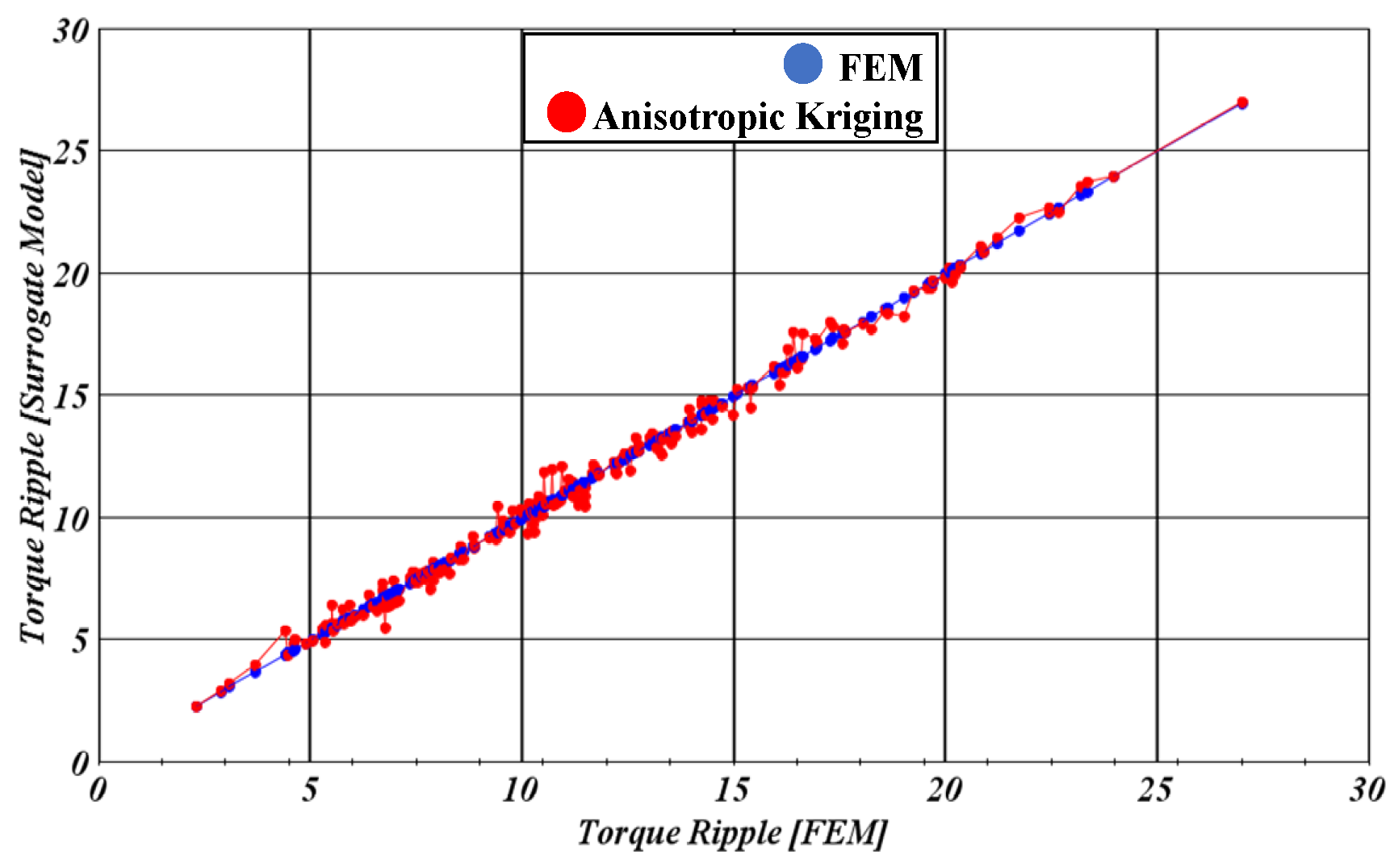
The DOE dataset, consisting of 1152 data points, was split into training and testing sets using an 80–20% ratio. The main modeling method employed in the paper is the Anisotropic Kriging model, along with the simple kriging method to demonstrate the accuracy of Anisotropic Kriging. The results are presented as a Surrogate model. In evaluating the model, two parameters, mean normalized error (MNE) and R 2 , are used. Additionally, the mean relative error (MRE) parameter is also utilized, but the evaluation primarily focuses on MNE and R 2 . The mathematical definitions of these two parameters are defined as
M N E = 1 m i = 1 m ε i 1 y m a x y m i n
R 2 = 1 i = 1 m ε i 2 1 i = 1 m y i M 2
where m represents the number of data to be evaluated, ε i is the difference between the predicted value and the actual value of the function, y i is the value of the ith design function, and y m i n , M, and y m a x are the minimum, average, and maximum values of the output values, respectively. The higher the accuracy of the system, the closer the R 2 value is to one and the MNE value is closer to zero.
Table 4 compares the performance of Anisotropic Kriging and standard Kriging Surrogate models across five optimization objectives. For torque per rotor volume, Anisotropic Kriging achieves an MNE of 0.000842 with R2 = 1, while standard Kriging achieves MNE = 0.000773 and R2 = 1, indicating highly accurate predictions for both models. Torque ripple predictions show slightly higher errors, with Anisotropic Kriging MNE = 0.018 and R2 = 0.993, compared to Kriging MNE = 0.018 and R2 = 0.984. Efficiency is predicted almost perfectly by both models (MNE = 0.0022 and 0.0024, R2 = 1). For the rotor lamination safety factor, Anisotropic Kriging shows lower error (MNE = 0.0224, R2 = 0.975) than Kriging (MNE = 0.0667, R2 = 0.862), while for maximum rotor lamination displacement, Anisotropic Kriging achieves MNE = 0.0024 and R2 = 1 versus Kriging MNE = 0.0067 and R2 = 0.999. Overall, these results indicate that both models are highly accurate, with Anisotropic Kriging performing slightly better for structural parameters.
Figure 6 displays the evaluation of the accuracy of the created model for torque ripple and safety factor, which is considered the most important optimization factor.

3.3. Hybrid Algorithms

The optimization problem for EMs is non-linear, which leads to many local optima due to its geometric nature. If we use a deterministic optimization method like SQP, we can quickly obtain a solution if the initial value is sufficiently good. However, deterministic methods are prone to becoming stuck in local optima. On the other hand, stochastic optimization methods like GA converge slowly, especially toward the end of the optimization when the objective function is close to optimal. This slowness is more noticeable in EM analysis due to the challenging multi-physical nature of finding the best points. This process is very important but also quite complex.
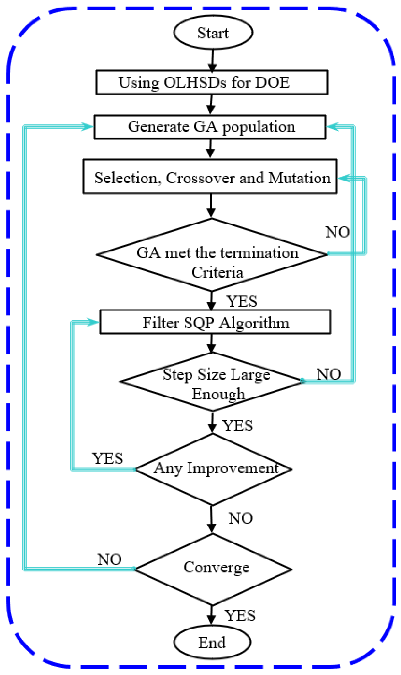
This paper discusses the use of a hybrid GA-SQP algorithm to optimize electric motors for electric vehicles. The algorithm begins with a GA to establish an initial point since the SQP method is sensitive to this. The GA runs until a certain objective function value or a specific number of generations is reached. During this time, the objective function becomes closer to the local or global optimum. Then, the SQP method is employed due to its high efficiency. If the step size becomes too small to continue, the algorithm switches back to GA to prevent becoming stuck in local optima. Alternatively, if SQP does not lead to any improvement in target performance, the algorithm switches back to GA. This process may repeat until the optimal solution is found.
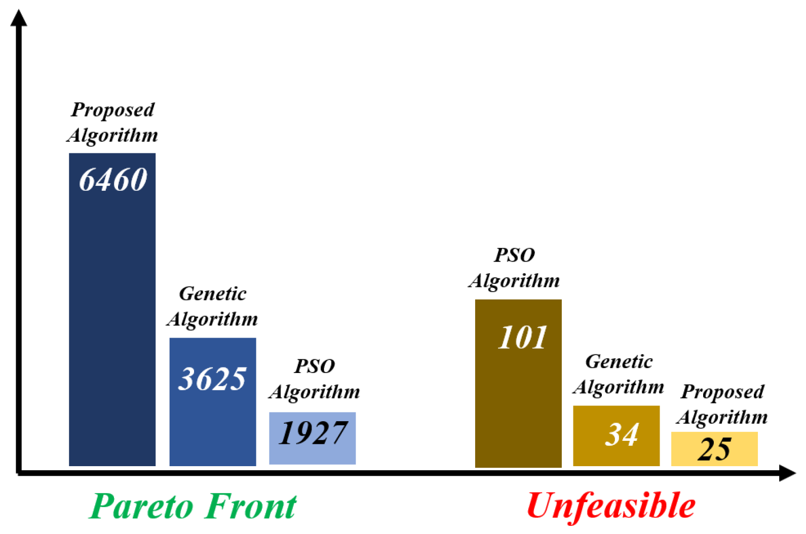
The flowchart of the algorithm used is displayed in Figure 7. As mentioned earlier, the combination of two genetic algorithms and SQP for geometric optimization of the EM has proven to be very effective due to its ability to handle local points and a variety of functions. To validate this assertion, 10,000 designs were created using the proposed hybrid algorithm and compared with two powerful and popular algorithms. The geometric optimization results for the EM are illustrated in Figure 8. As is evident from the comparison, the proposed algorithm outperforms the two GAs as well as the PSO algorithm, obtaining more points closer to the optimal point and reducing the search range.

3.4. Validation of the Proposed Algorithm with FEM

In this section, to simplify the optimization process, multi-objective optimization to single-objective optimization is set out. As a result, the objective in this part is to minimize the following objective function.
F m i n = c 1 × T v i T v + c 2 × L d a v L d a v i + c 3 × L s f i L s f + c 4 × η i η + c 5 × T r i T r i i
Here, T v i , T r i i , η i , L s f i , and L d a v i represent the initial values of torque per rotor volume, torque ripple, efficiency, rotor lamination safety factor, and rotor lamination displacement average, respectively. The denominator terms T v , T r i , η , L s f , and L d a v correspond to their updated or optimized values during the iterative process.
In the objective function mentioned (6), the maximum weight is assigned to reducing ripple torque. In the subsequent section, the most important mechanical objective function is the safety factor. The proposed method has been used to find the optimal point of the minimum objective function.
The algorithm’s results should be compared with the FEM results to ensure the accuracy of the proposed optimization process. The comparison is presented in Table 5, showing very close results. This demonstrates the effectiveness of the optimization process and the accurate selection of geometric variable ranges.

4. Fem Analysis and Discussions

In this section, the two ship-shaped U-shaped initial and optimized IPMSMs results are compared under the same environmental conditions and stimulation at both electromagnetic and mechanical levels. The objective function and associated performance improvements for initial and optimized IPMSMs are listed in Table 6.

4.1. The Investigation of the On-Load Magnetic Flux Density Distribution

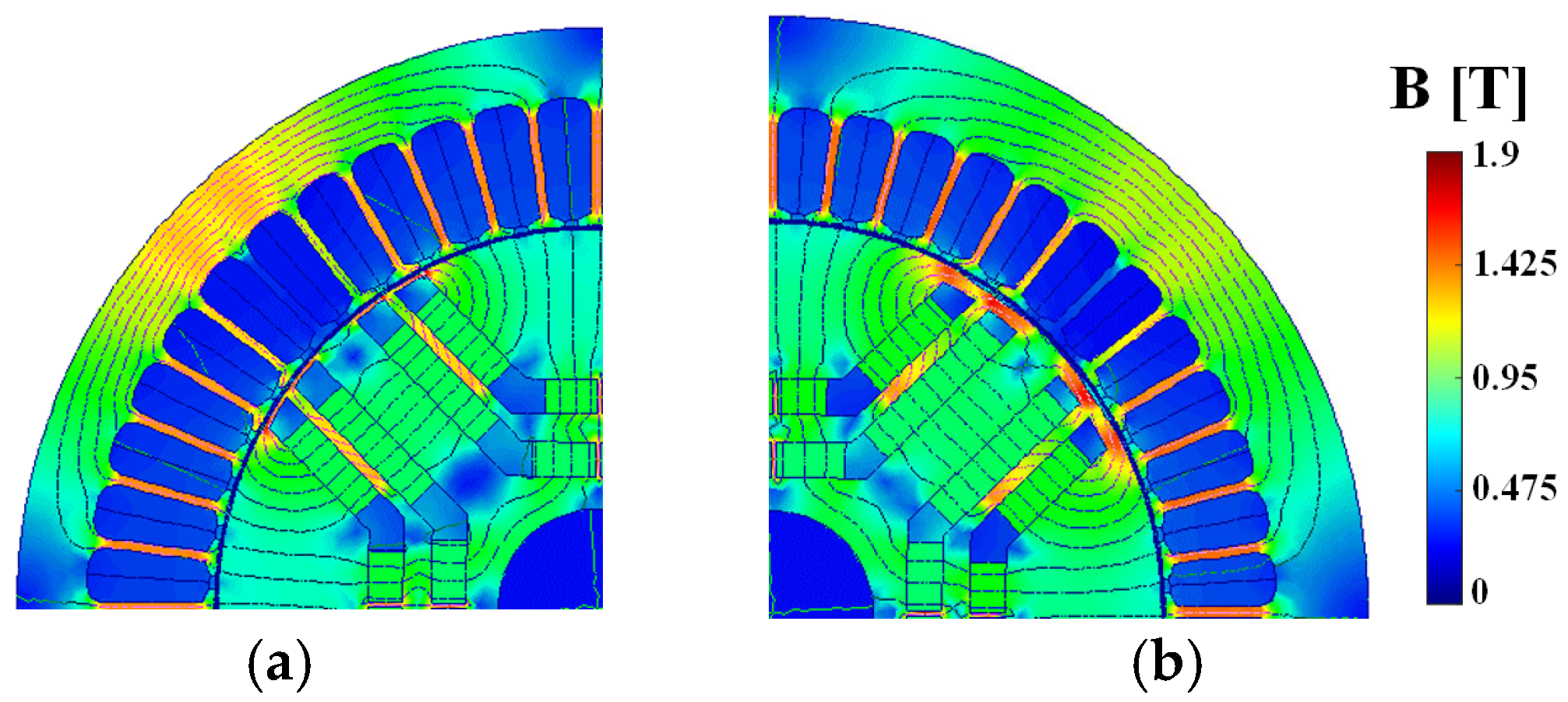
This section investigates the magnetic field density distribution in the stator and rotor cores at a speed of 4500 rpm. The investigation of the flux density distribution is a crucial aspect of the motor’s overall behavior. There are two ship-shaped U-shaped initial and optimized IPMSMs. The distribution of the flux density in these IPMSMs varies in these two types of EMs because of variations in the PM’s location and leakage PM flux. The flux density pattern in both IPMSMs is displayed in Figure 9. The optimized air-gap flux density is 0.58 T, while the average flux density in the initial IPMSMs’ air-gap is equivalent to 0.53 T.

4.2. The Investigation of the On-Load Magnetic Field Distribution

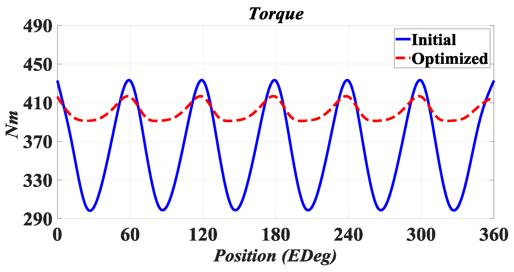
The behavior of the torque characteristics greatly affects the optimal performance of the engine for electric vehicle applications. The torque diagram of the initial and optimized IPMSMs is shown in Figure 10. According to Figure 10 and Table 6, it can be seen that the average torque of the improved optimized IPMSM has increased by 10.41% compared to the average torque of the initial IPMSMs. Therefore, the torque per rotor volume has increased in the improved design; also, the torque ripple in the optimized IPMSMs has decreased by 82.84% compared to initial IPMSMs and reached 6.2%.

4.3. The CPSR

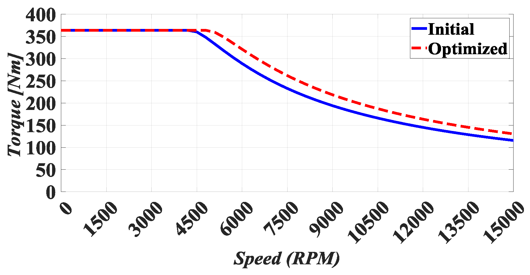
One of the key features of the motor utilized in the EV application is its maximum performance at high speeds. Figure 11 compares the maximum torque per ampere (MTPA) control method’s torque capabilities at various speeds between the ideal design and the first IPMSM. It has been demonstrated that the optimized IPMSM has a larger torque output at 15,000 rpm than the initial IPMSM and that the constant torque area’s maximum speed has increased. This demonstrates that the constant power speed range (CPSR) may be enhanced by choosing the right optimization functions and variables and by implementing a novel optimization technique.

4.4. Mechanical Characteristics

Mechanical problems are crucial in moving objects that transport people or loads since mechanical analysis is crucial in EMs, particularly in EVs. This section checks and compares important mechanical properties such as tension, rotor displacement, safety factor, noise and vibration, and more. Since there is always a small percentage of eccentricity in the rotor due to the uncertainty in the construction of the EMs, as a result, it is possible to perform the analysis of force, stress, and vibrations for the electric machine in a healthy state. In this article, to check the stresses on the electric motors under investigation, a characteristic called the safety factor, which is the ratio of the stress on the rotor to the YIELD STRESS of the lamination material, has been used. According to the results obtained in Table 6, the lowest stress at 4500 rpm revolutions per minute is related to the proposed structure and by its nature, the maximum safety factor is related to the final structure. This is due to the difference in the mass of the rotor and also the difference in the amount of torque fluctuations resulting from it.
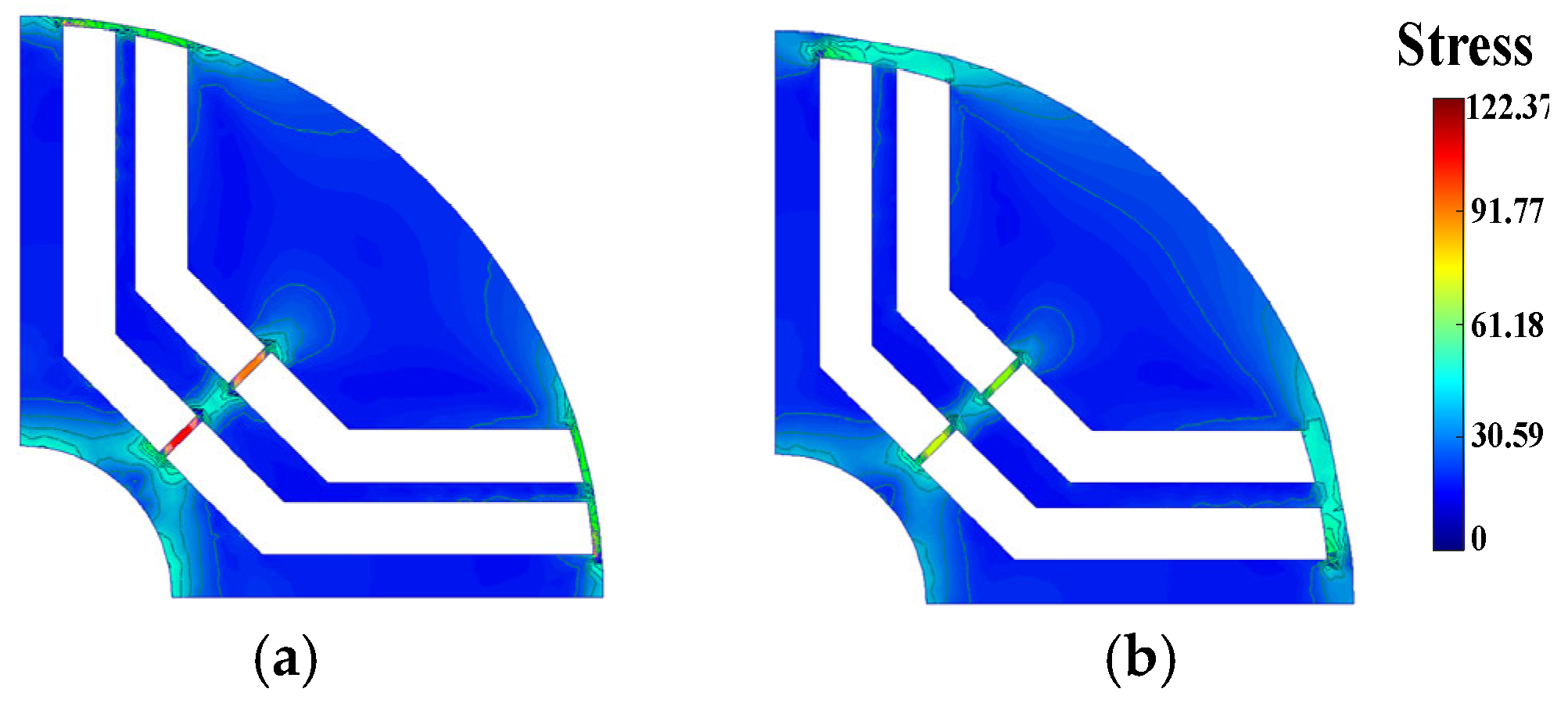
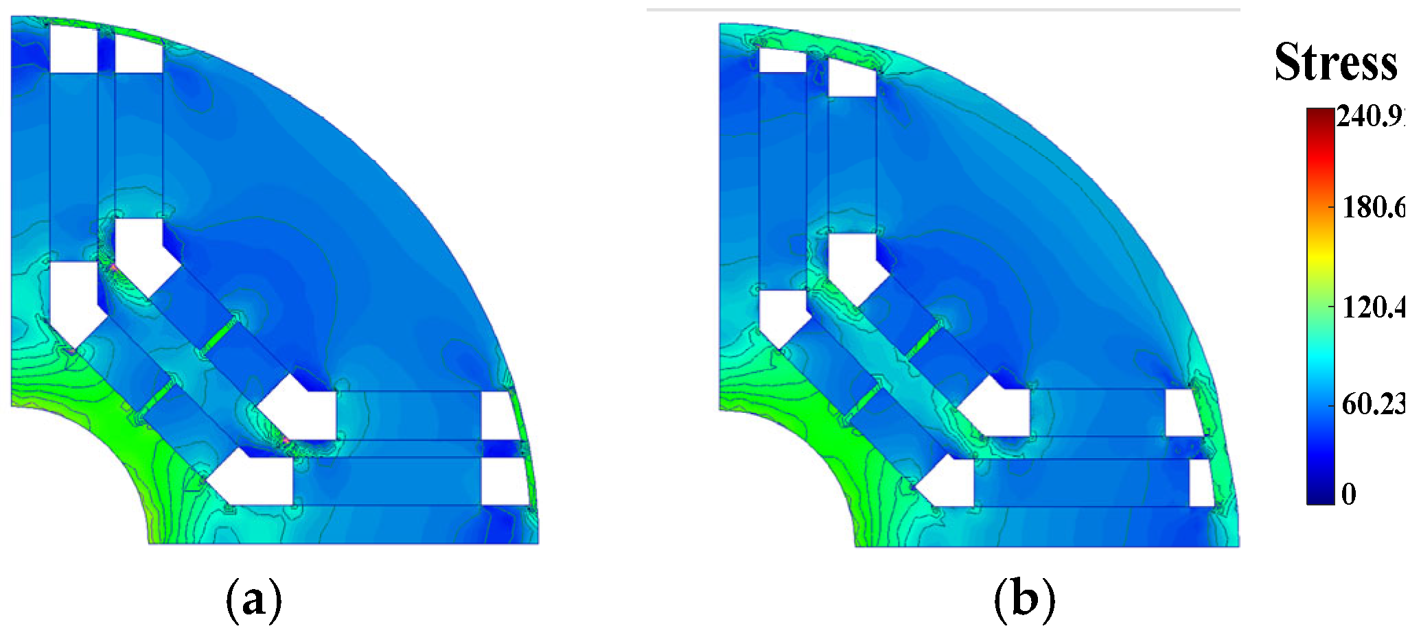
In Figure 12, the stress on the rotor at a speed of 4500 rpm is shown in the initial design and the proposed design without considering the effect of the magnet (not considering the fact that the PM is the worst condition and the stress should be reduced by considering the PM). Figure 13 also shows the stress on the two structures at 14,000 rpm, considering the magnet. As shown, the motor of the final design has less stress than the initial IPMSM; also, the maximum stress on the optimized IPMSM at a high speed of the tolerable stress of the used lamination (455 MPa) is much lower, and as a result, the proposed motor does not have a problem with stress at high speeds.
Displacement values resulting from transverse rotor vibrations are different under the same operating conditions and with different physical structures. As shown in Table 6, the displacement in the radial direction in the final structure is a significantly optimized version of IPMSM compared to the initial IPMSM.
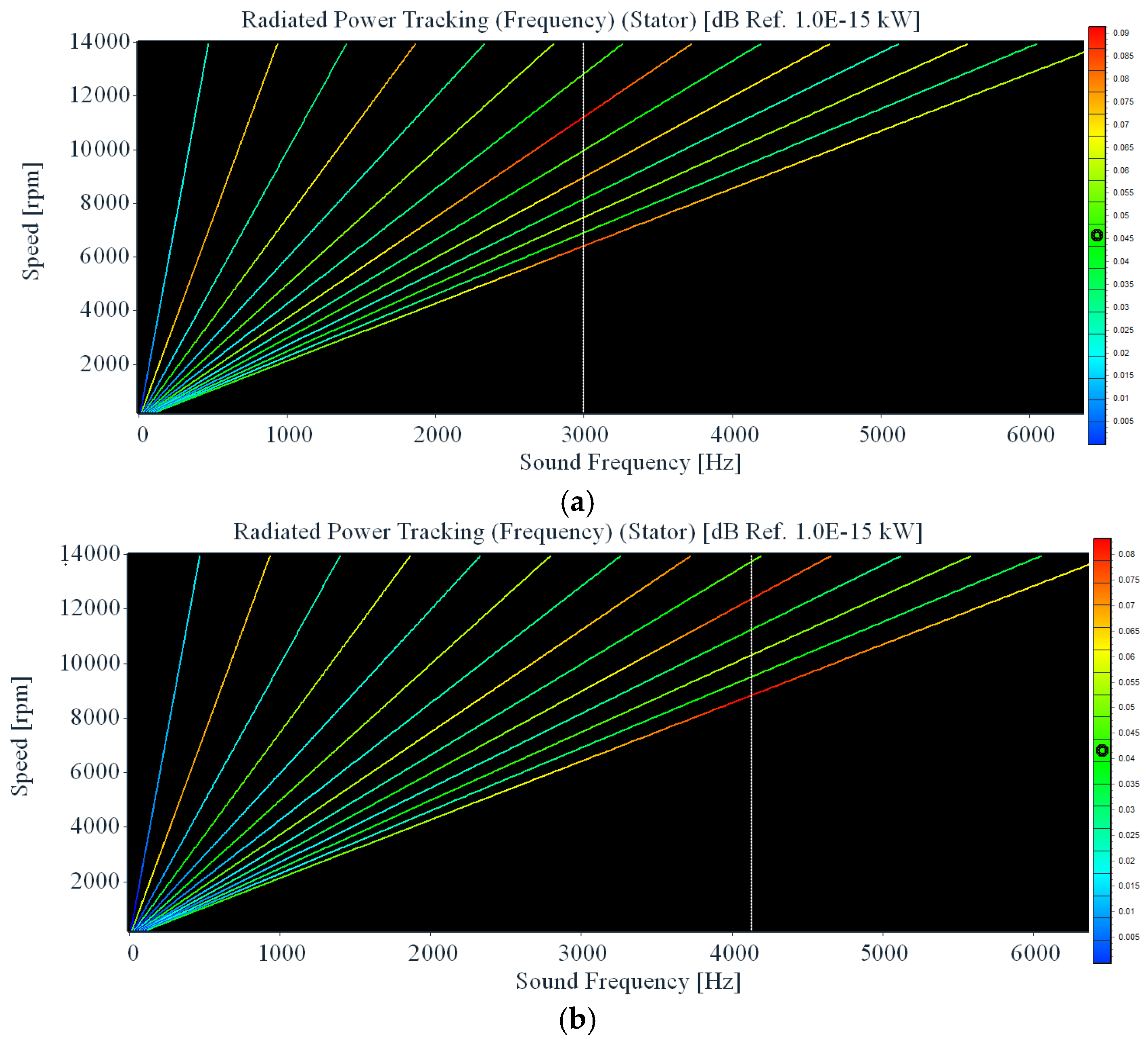
Figure 14a shows the sound response diagram according to the stimulation frequency and speed of the initial IPMSM, and Figure 14b shows the optimized IPMSM. According to this figure, at every point where the harmonic order of the frequency of the whole system has collided with the natural frequency of the system in the zero mode, at that speed, the most noise is generated from the motor. It can be seen that the natural frequency of the zero mode of the optimized IPMSM is more than the initial IPMSM, which is an important advantage. In (7), in general the values, the natural frequency is defined as
f n K / M
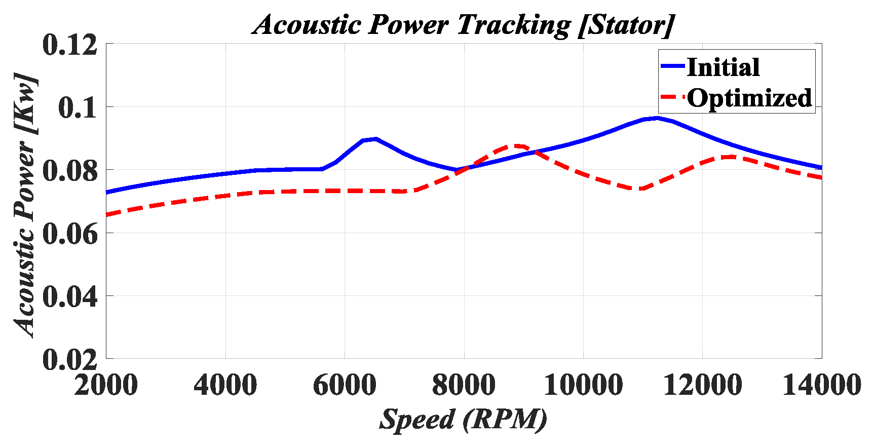
where K and M are the stiffness and mass of matter, respectively. An increase in the natural frequency leads to an increase in the stiffness of the motor, so it is expected that the stiffness of the optimized IPMSM in each mode is higher than the initial IPMSM. A large increase in hardness in different modes improves the mechanical behavior, and it is expected that the motor noise will be significantly reduced, and the engine will have maximum noise at higher speeds. Therefore, in Figure 15, the sound diagram of both initial and optimized IPMSMs is shown in terms of speed. According to Figure 15, it can be concluded that, in general, the noise of the optimized IPMSM has been greatly reduced and also that the maximum sound production by the EM has been created at a higher speed, which is a very important point. After mechanical analysis and the obtainment of the natural frequency and hardness of the motor, it should be checked at what speeds the designed electric motor should not work based on mechanical considerations.

5. Results Under Load EV

This section uses the Artemis Urban Duty cycle to model the load torque and the longitudinal dynamics model to determine the forces operating on the EV. Lastly, the MPTA control technique and load are used to simulate the optimized IPMSM’s efficiency map.

5.1. Longitudinal Dynamics Model

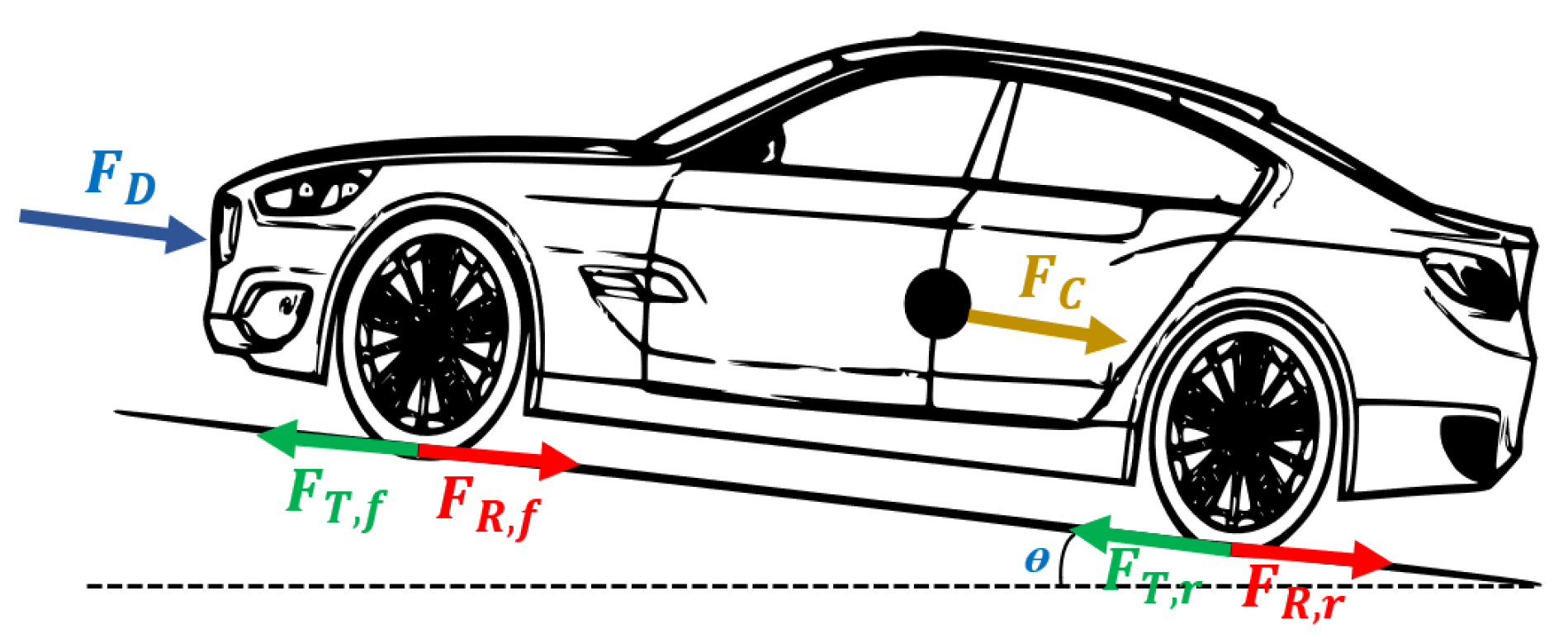
The motor is designed and the structure for EV application presented; the forces acting on the EV are calculated with the help of a longitudinal dynamics model. The total force resulting in longitudinal motion is the result of the following forces acting on the vehicle. Figure 16 shows the forces on the longitudinal dynamics of the vehicle.
Rolling force and climbing force are the forces of resistance to movement created by tires and the weight of the vehicle on the longitudinal axis and are defined as
F R = C r M v g c o s   θ
F c = M v g s i n   θ
where M v and g are defined as the product of inertial mass and the average gravitational pull of the earth, respectively. Tires on rolled gravel have a set rolling resistance coefficient ( C r ) of 0.02 that is affected by various parameters, including tire composition, structure, temperature, air pressure, tread geometry, road roughness, and substance.
Aerodynamic force is the force created by the wind that slows down the vehicle. It can be written as
F D = 1 2 ρ v l 2 C d A
where ρ is the air density, C d . A is the coefficient of drag times active area for an EV, and v l is the maximum speed. Traction force is the force responsible for creating movement through dry friction between the tires and the road surface, defined as
F T = F T , f + F T , r
Rolling resistance of the tires (represented by rolling resistance torque F T , f and F T , r in Figure 16). The total longitudinal force is equal to the sum of the effective forces as a result in
F a = F R + F D + F c + F T

5.2. Load Torque Modeling Under Artemis Urban Duty Cycle

The inertial torque needed to accelerate the rotor ( I rotor ), shaft ( I shaft ), and wheels ( I wheels ) is calculated as
T inertia = α r I rotor + I shaft + I wheels n d
where α r is the angular acceleration and n d is the gear ratio.
Finally, the torque of the EM required with a tire radius ( r w ) for the use of the EV is expressed as
T motor = F a r w n d + T inertia
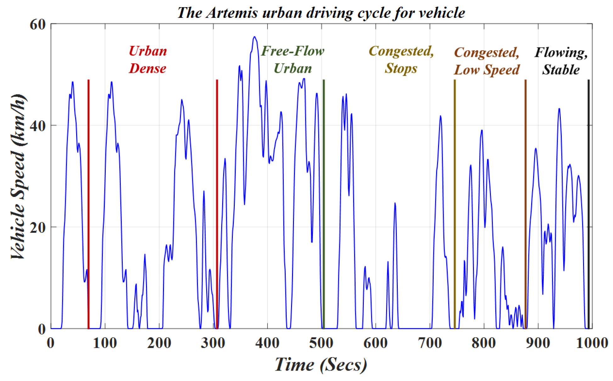
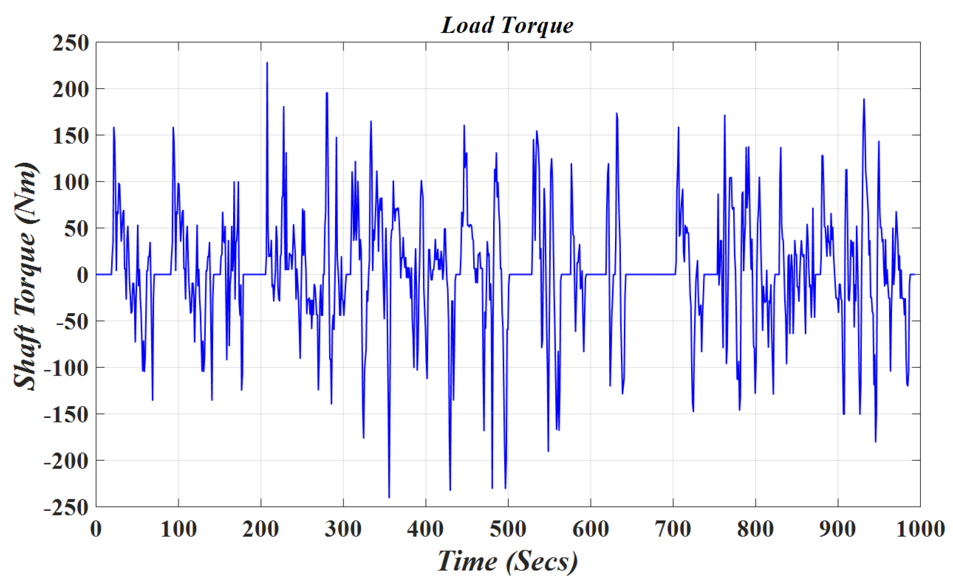
After modeling the torque necessary to accurately analyze the behavior of the EM under the load of the EV, the motor is developed in the average speed range because it is intended for urban applications. The Artemis Urban standard is the benchmark used to assess the behavior of the suggested motor. The average speed and distance traveled, according to these criteria, are 17.7 km/h and 4.87 km, respectively, across the European region. Figure 17 depicts the Artemis urban driving cycle for automobiles. The load torque according to the physical characteristics of the Tesla Model S vehicle is then modeled for this application in Figure 17, Equation (13), and this torque is displayed in Figure 18.

5.3. Efficiency Map

Before making the efficiency map, it is important to consider the factors because the load is connected to the proposed electric motor’s shaft. Different techniques are used by electric motors to produce torque. The interplay between the stator current distribution and the air gap flux distribution produces torque in synchronous motors. The two distributions must partially overlap for torque to be generated by these interacting forces. To achieve optimal performance, control systems ought to take these attributes into account and run the motor at its maximum torque point. MTPA control refers to methods of operating motors that maximize torque while taking into account both PM and reluctance torque. When the lowest stator current is used to accomplish a certain maximum torque-speed, this condition arises.
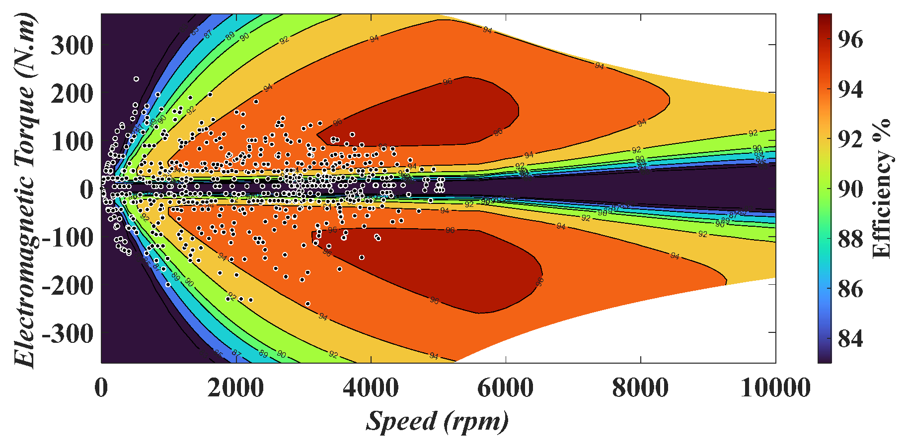
Figure 19 shows the efficiency map of the optimized IPMSM under the MTPA control approach, coupled with the EV’s modeled load. The blue points on the map indicate the locations of the coupled load. As demonstrated, the optimized IPMSM successfully handled the modeled load based on European driving standards while maintaining high efficiency throughout the cycle, achieving an average efficiency of 93.28%. Furthermore, a direct performance comparison with a benchmark motor (Tesla Model S) revealed that, under the same driving cycle, the optimized motor achieved 0.5% higher efficiency (93.28% vs. 92.78%).

6. Conclusions

This study compared V-shaped and U-shaped IPMSM designs to identify the optimal configuration for EV applications, focusing on torque ripple, power, and efficiency. A ship-shaped notch was introduced in the bridge area between the double U-shaped layers to further reduce torque ripple. Key design variables were identified, and a robust optimization framework combining Pearson Correlation, Anisotropic Kriging-based Surrogate modeling, MOGA, and SQP was applied for the first time to these machines.
Validation using FEM, GA, and PSO confirmed that the optimized PMSM outperforms alternative designs in EV performance indices. The proposed motor efficiently handles European driving loads, achieves high average efficiency, and exhibits reduced torque ripple, leading to lower vibration and noise. These results demonstrate the potential of the optimized PMSM as a high-performance, low-noise solution for electric vehicles.
Author Contributions

Conceptualization, A.A.; methodology, A.A.; writing—original draft preparation, A.A. and F.F.; writing—review and editing, F.M.; supervision, A.V. and N.J.B.; funding acquisition, N.J.B. All authors have read and agreed to the published version of the manuscript.

Funding

This research received no external funding.

Data Availability Statement

The raw data supporting the conclusions of this article will be made available by the authors on request.

Conflicts of Interest

The authors declare no conflicts of interest.

Abbreviations

IPMSMInterior permanent magnet synchronous motors
EVElectric vehicle
MOGAMulti-Objective Genetics Algorithm
SQPSurrogate Quadratic Programming
PSOParticle Swarm Optimization algorithm
GAGenetics Algorithm
FEMFinite Element Method
EMsElectric motors
PMSMsPermanent magnet synchronous motors
SMPMSMsSurface-mounted permanent magnet synchronous motors
OEMOrthogonal experimental method
MIGAMulti-island genetic algorithm
RBF-NNsRadial basis function neural networks
DOEDesign of experiment
NSGANon-dominated sorting genetic algorithm
GRSMGlobal response surface method
SASensitivity analysis
RSMResponse surface method
OLHSDOptimal Latin hypercube sampling designs
MNEMean normalized error
MREMean relative error
MTPAMaximum torque per ampere
CPSRConstant power speed range

References

  1. Yang, Y.; Liu, C.; Lai, S.-K.; Chen, Z.; Chen, L. Frequency-dependent equivalent impedance analysis for optimizing vehicle inertial suspensions. Nonlinear Dyn. 2025, 113, 9373–9398. [Google Scholar] [CrossRef]
  2. Farrokh, F.; Torkaman, H.; Vahedi, A.; Banejad, M. Design of Dual-Rotor Dual-Stator Axial-Field Flux-Switching PM Motor with Low-Cogging Torque and Low-Torque Ripple. In Proceedings of the 2023 3rd International Conference on Electrical Machines and Drives (ICEMD), Tehran, Iran, 20–21 December 2023; pp. 1–5. [Google Scholar] [CrossRef]
  3. Balasubramanian, L.; Bhuiyan, N.A.; Javied, A.; Fahmy, A.A.; Belblidia, F.; Sienz, J. Design and Optimization of Interior Permanent Magnet (IPM) Motor for Electric Vehicle Applications. CES Trans. Electr. Mach. Syst. 2023, 7, 202–209. [Google Scholar] [CrossRef]
  4. Farrokh, F.; Vahedi, A.; Torkaman, H.; Banejad, M. Design and Comparison of Dual-Stator Axial-Field Flux-Switching Permanent Magnet Motors for Electric Vehicle Application. IET Electr. Syst. Transp. 2023, 13, e12074. [Google Scholar] [CrossRef]
  5. Li, S.; Tong, W.; Wu, S.; Tang, R. General Analytical Model for Electromagnetic-Thermal Bi-Directional Coupling of IPM Motors in Electric Vehicles Considering Different Rotor Structures. IEEE Trans. Veh. Technol. 2024, 73, 16470–16480. [Google Scholar] [CrossRef]
  6. Lin, X.; Liu, J.; Liu, Z.; Gao, Y.; Peretti, L.; Wu, L. Model-Free Current Predictive Control for PMSMs with Ultralocal Model Employing Fixed-Time Observer and Extremum-Seeking Method. IEEE Trans. Power Electron. 2025, 40, 10682–10693. [Google Scholar] [CrossRef]
  7. Xu, R.; Shen, X.; Lin, X.; Liu, Z.; Xu, D.; Liu, J. Robust Model Predictive Control of Position Sensorless-Driven IPMSM Based on Cascaded EKF-LESO. IEEE Trans. Transp. Electrif. 2025, 11, 8824–8832. [Google Scholar] [CrossRef]
  8. Lin, X.; Xu, R.; Yao, W.; Gao, Y.; Sun, G.; Liu, J.; Peretti, L.; Wu, L. Observer-Based Prescribed Performance Speed Control for PMSMs: A Data-Driven RBF Neural Network Approach. IEEE Trans. Ind. Inform. 2024, 20, 7502–7512. [Google Scholar] [CrossRef]
  9. Du, G.; Li, N.; Zhou, Q.; Gao, W.; Wang, L.; Pu, T. Multi-Physics Comparison of Surface-Mounted and Interior Permanent Magnet Synchronous Motor for High-Speed Applications. Machines 2022, 10, 700. [Google Scholar] [CrossRef]
  10. Takarli, R.; Amini, A.; Khajueezadeh, M.; Zarbil, M.S.; Vahedi, A.; Kiyoumarsi, A.; Tarzamni, H.; Kyyra, J. A Comprehensive Review on Flywheel Energy Storage Systems: Survey on Electrical Machines, Power Electronics Converters, and Control Systems. IEEE Access 2023, 11, 81224–81255. [Google Scholar] [CrossRef]
  11. Wang, S.C.; Nien, Y.C.; Huang, S.M. Multi-Objective Optimization Design and Analysis of V-Shape Permanent Magnet Synchronous Motor. Energies 2022, 15, 3496. [Google Scholar] [CrossRef]
  12. Hwang, M.H.; Han, J.H.; Kim, D.H.; Cha, H.R. Design and Analysis of Rotor Shapes for IPM Motors in EV Power Traction Platforms. Energies 2018, 11, 2601. [Google Scholar] [CrossRef]
  13. Hong, S.G.; Park, I.H. Continuum-Sensitivity-Based Optimization of Interior Permanent Magnet Synchronous Motor with Shape Constraint for Permanent Magnet. IEEE Trans. Magn. 2020, 56, 1–4. [Google Scholar] [CrossRef]
  14. Hao, J.; Suo, S.; Yang, Y.; Wang, Y.; Wang, W.; Chen, X. Optimization of Torque Ripples in an Interior Permanent Magnet Synchronous Motor Based on the Orthogonal Experimental Method and MIGA and RBF Neural Networks. IEEE Access 2020, 8, 27202–27209. [Google Scholar] [CrossRef]
  15. Wu, S.; Sun, X.; Tong, W. Optimization Design of High-Speed Interior Permanent Magnet Motor with High Torque Performance Based on Multiple Surrogate Models. CES Trans. Electr. Mach. Syst. 2022, 6, 235–241. [Google Scholar] [CrossRef]
  16. Zhu, X.; Yang, J.; Xiang, Z.; Jiang, M.; Zheng, S.; Quan, L. Robust-Oriented Optimization Design for Permanent Magnet Motors Considering Parameter Fluctuation. IEEE Trans. Energy Convers. 2020, 35, 2066–2075. [Google Scholar] [CrossRef]
  17. Orosz, T.; Rassõlkin, A.; Kallaste, A.; Arsénio, P.; Pánek, D.; Kaska, J.; Karban, P. Robust Design Optimization and Emerging Technologies for Electrical Machines: Challenges and Open Problems. Appl. Sci. 2020, 10, 6653. [Google Scholar] [CrossRef]
  18. Islam, M.S.; Chowdhury, M.; Shrestha, A.; Islam, M.; Husain, I. Multiload Point Optimization of Interior Permanent Magnet Synchronous Machines for High-Performance Variable-Speed Drives. IEEE Trans. Ind. Appl. 2021, 57, 427–436. [Google Scholar] [CrossRef]
  19. Xu, R.; Tong, W. Multi-Objective Hierarchical Optimization of Interior Permanent Magnet Synchronous Machines Based on Rotor Surface Modification. CES Trans. Electr. Mach. Syst. 2022, 6, 352–358. [Google Scholar] [CrossRef]
  20. Xing, Z.; Wang, X.; Zhao, W.; Li, X.; Xiong, L.; Zhang, X. Optimization Design of Interior Permanent Magnet Synchronous Motor with U-Shaped Rotor for Low-Level Torque Ripple and Electromagnetic Vibration. IEEE Trans. Transp. Electrif. 2024, 10, 1995–2007. [Google Scholar] [CrossRef]
  21. Amini, A.; Khajueezadeh, M.S.; Vahedi, A. A Multi-Objective and Multi Level Optimization of IPMSM Case Study Dynamometer. In Proceedings of the 2023 3rd International Conference on Electrical Machines and Drives, ICEMD 2023, Tehran, Iran, 20–21 December 2023. [Google Scholar] [CrossRef]
  22. Mahmouditabar, F.; Vahedi, A.; Takorabet, N. Design and Analysis of Interior Permanent Magnet Motor for Electric Vehicle Application Considering Irreversible Demagnetization. IEEE Trans. Ind. Appl. 2022, 58, 284–293. [Google Scholar] [CrossRef]
  23. Mahmouditabar, F.; Vahedi, A.; Takorabet, N. Robust Design of BLDC Motor Considering Driving Cycle. IEEE Trans. Transp. Electrif. 2023, 10, 1414–1424. [Google Scholar] [CrossRef]
  24. Zheng, J.; Zhao, W.; Lee, C.H.T.; Ji, J.; Xu, G. Improvement Torque Performances of Interior Permanent-Magnet Machines. CES Trans. Electr. Mach. Syst. 2019, 3, 12–18. [Google Scholar] [CrossRef]
  25. Lim, D.K.; Yi, K.P.; Woo, D.K.; Yeo, H.K.; Ro, J.S.; Lee, C.G.; Jung, H.K. Analysis and Design of a Multi-Layered and Multi-Segmented Interior Permanent Magnet Motor by Using an Analytic Method. IEEE Trans. Magn. 2014, 50, 1–8. [Google Scholar] [CrossRef]
  26. Huynh, T.A.; Hsieh, M.F. Irreversible Demagnetization Analysis for Multilayer Magnets of Permanent Magnet-Assisted Synchronous Reluctance Machines Considering Current Phase Angle. IEEE Trans. Magn. 2019, 55, 1–9. [Google Scholar] [CrossRef]
  27. Huynh, T.A.; Hsieh, M.F.; Shih, K.J.; Kuo, H.F. An Investigation into the Effect of PM Arrangements on PMa-SynRM Performance. IEEE Trans. Ind. Appl. 2018, 54, 5856–5868. [Google Scholar] [CrossRef]
  28. Amini, A.; KhajueeZadeh, M.; Vahedi, A. Reliability and Lifetime Analysis on Permanent Magnet Motors in Elevator: Case Study PMA-SynRM & IPMSM. In Proceedings of the 2023 3rd International Conference on Electrical Machines and Drives (ICEMD), Tehran, Iran, 20–21 December 2023; pp. 1–6. [Google Scholar] [CrossRef]
Figure 1. Three variables of the ship-shaped notch rotor.
Energies 18 04527 g001
Figure 2. Variables of the ship-shaped notch rotor.
Energies 18 04527 g002
Figure 3. Three variables on reducing torque ripple with SA. (a) Notch depth. (b) Notch arc.
Energies 18 04527 g003
Figure 4. Flowchart of the optimization design process.
Energies 18 04527 g004
Figure 5. Correlation analysis results.
Energies 18 04527 g005
Figure 6. Validation of a Surrogate model for torque ripple and safety factor with FEM.
Energies 18 04527 g006
Figure 7. Flowchart of the hybrid algorithm.
Energies 18 04527 g007
Figure 8. Comparison of the proposed hybrid algorithm with the GA and PSO algorithms.
Energies 18 04527 g008
Figure 9. The distribution of the flux density in ship-shaped U-shaped IPMSMs. (a) Initial. (b) Optimized.
Energies 18 04527 g009
Figure 10. The output torque for the rotor mechanical position in the initial and optimized IPMSMs.
Energies 18 04527 g010
Figure 11. The torque curves vs. speeds in initial and optimized IPMSMs.
Energies 18 04527 g011
Figure 12. Von Mises stress of the rotor without PMs IPMSMs. (a) Initial. (b) Optimized.
Energies 18 04527 g012
Figure 13. Von Mises stress of the rotor with PMs IPMSMs. (a) Initial. (b) Optimized.
Energies 18 04527 g013
Figure 14. The sound response with frequency and speed of IPMSMs. (a) Initial. (b) Optimized.
Energies 18 04527 g014
Figure 15. The sound and noise of IPMSMs.
Energies 18 04527 g015
Figure 16. Schematic representation of the forces acting on an EV.
Energies 18 04527 g016
Figure 17. The Artemis urban driving cycle for vehicles.
Energies 18 04527 g017
Figure 18. Load torque under the Artemis urban driving cycle.
Energies 18 04527 g018
Figure 19. The efficiency map and torque-speed curves of the optimized IPMSM.
Energies 18 04527 g019
Table 2. Comparison of the performance for IPMSMs.
ObjectiveUnitV-ShapedU-Shaped
Maximum torqueNm160.2161.3
Efficiency%9595.1
Torque ripple%7.275.29
Rotor Lamination displacementmm0.002530.00345
Rotor Lamination safety factorRatio%6.335.32
Table 3. Specifications of the U-shaped IPMSM.
ParameterDiscerptionUnitValue
Rated P n Rated powerKW168
n n Rated speedr/min4500
T n Rated torqueNm356
I p e a k Line peak currentA777
Stator R o / R i Outer/inner radiusmm253/155
N s Slot Numbermm48
h s Slot depthmm26
w t Tooth widthmm2
b o Slot opening heightmm1.2
w o Slot opening widthmm2.8
LStack lengthmm170
Rotor L 1 / L 2 L1 Dia/L2 Diamm53/78.61
l g Air gapmm0.7
l P M 1 PM outer length layer 1mm27.3
l P M 2 PM outer length layer 2mm21.05
w B g 1 Bridge thickness layer 1mm1.5
w B g 2 Bridge thickness layer 2mm1.5
w w b 1 PM web thickness layer 1mm11.22
l w b 2 PM web thickness layer 2mm30.3
β o Notch arc outermm0
β i Notch arc innermm0
β d Notch depthmm0
Table 4. The Surrogate model results.
Optimization ObjectiveAnisotropic KrigingKriging
MNE R 2 MNE R 2
Torque per Rotor Volume0.00084210.0007731
Torque Ripple0.0189.93 × 10−10.0189.84 × 10−1
Efficiency0.002210.00241
Rotor Lamination Safety Factor0.02249.75 × 10−10.06678.62 × 10−1
Rotor Lamination Displacement Maximum0.002410.00679.99 × 10−1
Table 5. Validation of the proposed algorithm with FEM.
Optimization ObjectiveUnitValue
Proposed Hybrid AlgorithmFEM
Torque per Rotor Volume KNm / m 3 127.14127.27
Torque Ripple%93.7093.75
Efficiency%6.36.2
Rotor Lamination Safety FactorRatio5.115.28
Rotor Lamination Displacement Maximummm0.00560.0057
Table 6. Electromagnetic and mechanical performance comparison of initial and optimized ship-shaped U-shaped IPMSMs.
Optimization ObjectiveUnitValue
InitialOptimized
Torque per Rotor Volume KNm / m 3 115.26127.27
Efficiency%94.2493.75
Torque ripple%36.146.2
Rotor Lamination Safety FactorRatio3.7185.28
Rotor Lamination Displacement Averagemm0.008430.0057
Rotor Lamination Displacement Maxmm0.014640.01025
Disclaimer/Publisher’s Note: The statements, opinions and data contained in all publications are solely those of the individual author(s) and contributor(s) and not of MDPI and/or the editor(s). MDPI and/or the editor(s) disclaim responsibility for any injury to people or property resulting from any ideas, methods, instructions or products referred to in the content.