Article

Novel Single-Core Phase-Shifting Transformer: Configuration, Analysis and Application in Loop Closing

1
State Grid Yangzhou Power Supply Company, Yangzhou 225009, China
2
State Grid Yizheng Power Supply Branch Company, Yangzhou 211400, China
3
School of Electrical Engineering, Southeast University, Nanjing 210096, China
*
Author to whom correspondence should be addressed.
Energies 2025, 18(17), 4500; https://doi.org/10.3390/en18174500
Submission received: 12 July 2025 / Revised: 21 August 2025 / Accepted: 22 August 2025 / Published: 24 August 2025
(This article belongs to the Special Issue Advances in Permanent Magnet Motor and Motor Control)

Abstract

Phase-shifting transformers (PST) are widely used to control power flows. However, conventional designs can vary only the phase angle, leaving the voltage magnitude unaffected or requiring structurally complex devices. This study proposes a compact PST topology that realizes simultaneous, decoupled control of both voltage magnitude and phase angle through two coordinated sets of windings. Closed-form equations are derived to link the phase-shifting and voltage regulation windings turn ratios to any target magnitude ratio and phase-shift angle, providing a unified design framework that guarantees the full practical operating range. Steady-state tests verify that the device can change the phase or adjust the magnitude independently without cross-coupling. Dynamic tests demonstrate that, when a tap command is issued, the line currents and active power converge to new set-points within a few fundamental periods and with minimal oscillation. Furthermore, the PST’s application to loop closing operations in 220 kV networks is investigated, where simulation results show it can suppress loop closing currents by over 90% under adverse voltage mismatch conditions. These results confirm that the proposed PST offers a fast, economical alternative to Flexible AC Transmission Systems (FACTS) equipment for real-time power flow balancing, renewable integration and inter-area exchange in modern transmission networks.

1. Introduction

The rapid rise of variable renewable generation and the intensification of cross-border power exchanges are pushing conventional AC grids to their stability and capacity limits. Because the active-power flow is passively governed by line impedances, operators often face bottlenecks, congestion and curtailment of renewables [1,2]. FACTS were introduced to give grids the missing controllability.
Within FACTS, the Unified Power Flow Controller (UPFC) offers full, independent regulation of voltage magnitude, phase angle and line impedance [3]. Yet its high capital, operation, and maintenance costs hinder large-scale adoption [4]. PST is therefore an attractive, field-proven alternative: using only electromagnetic components, it steers power flow by injecting a controllable phase angle across the line at a fraction of the UPFC’s cost [5,6].
Recent work seeks to extend PST capability beyond pure phase shifting. Two-core asymmetric PSTs (APST) raise transfer limits [2], while the asymmetrical controllable PST (ACPST) adds simultaneous control of longitudinal and quadrature voltages. These efforts expose the central design question: single-core versus dual-core construction. Dual-core PSTs, with separate series and exciter units, dominate high-voltage systems because they can deliver wider phase-shift ranges and independently tune voltage magnitude and phase. Single-core designs merge both functions onto one magnetic core, gaining simpler construction, lower cost, smaller footprint, and higher efficiency—advantages compelling for networks of 110 kV and below. Achieving dual-core controllability within an economical single-core design remains a primary research goal.
Multiple topologies try to bridge this gap, but each sacrifices at least one key attribute. Asymmetrical PSTs (APSTs), for instance, suffer from an inherent voltage rise; in a 230 V nominal system, studies show that the output voltage can exceed 270 V—a rise of over 17%. Conversely, symmetrical PSTs (SPSTs) provide voltage stability, with typical variations as low as a 2.6 V drop, but this comes at the cost of having no independent voltage magnitude control capability [7]. Furthermore, the regulation accuracy of conventional designs is limited, with some topologies exhibiting regulation errors as high as 18.1% in network simulations. Even the “independent” fast PST, expressly simplified for industry use, still shows limited voltage and phase-shift ranges of only ±4.2% and ±12°, respectively—considerably narrower than the wide ranges achievable by dual-core systems [8].
Loop closing operations in distribution networks often trigger severe loop closing currents, endangering equipment and occasionally causing protection mis-operations. As distributed generation penetrates deeper into feeders, the pre-closing disparities in voltage magnitude and phase become harder to predict, further complicating secure loop-closing procedures [9]. Conventional remedies—unsynchronized tie-switch closing or series pre-insertion resistors—either fail when residual flux or load conditions change or impose extra losses and cost. PST offers a more advanced approach: by injecting a composite voltage that simultaneously aligns amplitude and phase, it brings the two feeder voltages into near synchronism just before contact, thereby suppressing the loop closing current [10]. However, existing PST implementations still couple voltage-magnitude and phase-angle control, thereby restricting their viable deployment locations and overall effectiveness [11].
A clear research gap therefore exists: devising a PST that breaks the entrenched trade-off among performance, complexity and cost. The sought-after device must deliver truly decoupled, wide-range control of voltage amplitude and phase angle—capabilities now associated with costly dual-core systems or UPFCs—while preserving the compactness and efficiency of a single-core transformer.
This paper proposes a novel single-core phase-shifting transformer topology engineered to address these long-standing limitations. The key to its differentiated performance is the specific series connection of these windings: each output phase voltage is synthesized by combining a voltage regulation winding from its own core limb with a phase-shifting winding from an adjacent limb. This is accomplished while retaining the intrinsic structural simplicity and high efficiency of a single-core architecture. By independently regulating the turns ratios of the voltage regulation winding (nE1) and the phase-shifting winding (nE2) in the analytical control equations, the design achieves fully decoupled adjustment of voltage magnitude and phase angle, enabling a complete ±180° phase-shifting range. Additionally, this work develops a fast, analytical control method that enables the proposed PST to suppress loop closing currents by over 90% in distribution networks with significant voltage mismatches. Furthermore, its theoretical advantages are confirmed through a thorough simulation of the proposed concept using the PLECS simulation environment.
The remainder of this paper is organized as follows: Section 2 presents the basic principle of PSTs. Section 3 describes the topology. Section 4 derives the mathematical relationships for its phase-shifting and voltage regulation capabilities. Section 5 presents a loop closing current control method with the proposed PST’s control capability. Section 6 provides detailed simulation and experiment results, and Section 7 concludes the paper.

2. Basic Principle of PST

The phase-shifting transformer is a specialized power transformer designed to control active power flow in transmission networks by introducing a controllable phase shift between input and output voltages. The fundamental principle relies on the phasor addition of voltages to achieve the desired phase displacement.

2.1. Power Flow Control Mechanism

As shown in Figure 1, the active-power transfer over a lossless transmission line of reactance XL is governed by
P = U S U R X L sin ( θ S θ R )
where USθS and URθR are the sending-end and receiving-end voltage phasors. Inserting a PST introduces an adjustable phase-shift δ, so that the effective angle difference becomes θSθR + δ. The transferable power is therefore
P PST = U S U R X L sin ( θ S θ R + δ ) .
By tuning δ, system operators can redistribute active power among parallel paths or relieve overloaded lines, without altering busbar voltage magnitudes.

2.2. Voltage-Phasor Relationships

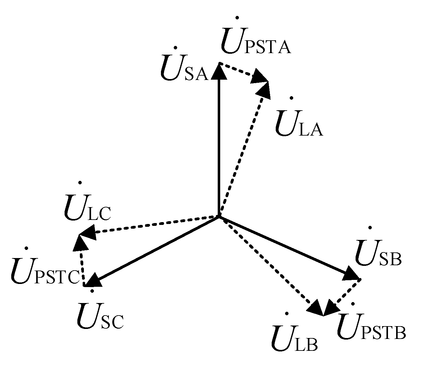
The PST achieves the desired phase shift by phasor addition: it injects a series compensation phasor ΔUPST,x in series with each phase. Figure 2 illustrates the phasor diagram for a three-phase system, showing how the phase-shifting transformer modifies each phase voltage by injecting a controllable series phasor. For phases A, B and C:
U ˙ L A = U ˙ S A + Δ U ˙ P S T , A U ˙ L B = U ˙ S B + Δ U ˙ P S T , B U ˙ L C = U ˙ S C + Δ U ˙ P S T , C
Because the magnitude of ΔUPST,x controllable (via tap-changer steps and/or winding reversal), the PST provides a fast, flexible tool for regulating line power flow while maintaining voltage support.

3. Topology Structure of the Novel Single-Core PST

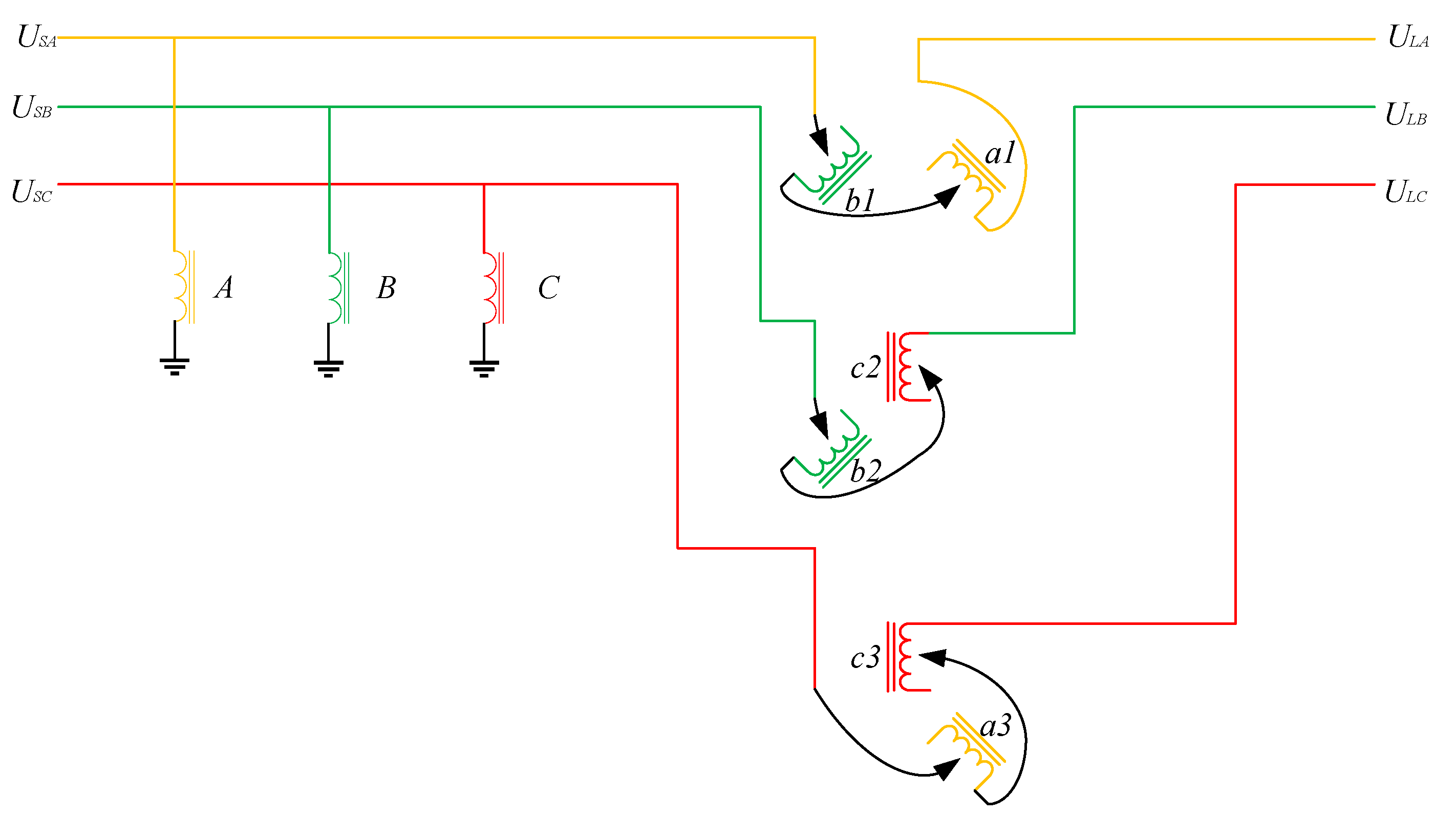
As shown in Figure 3, the proposed single-core phase-shifting transformer employs a unique winding arrangement on a three-phase core. The primary side consists of three windings (A, B, C) connected to ground and energized by the grid source voltages USA, USB and USC.
The secondary side features six windings distributed as follows:
  • Phase A core limb: windings a1 and a3
  • Phase B core limb: windings b1 and b2
  • Phase C core limb: windings c2 and c3
The secondary windings are connected in series pairs to generate the required compensation voltages:
  • For phase A output: windings a1 and b1 in series
  • For phase B output: windings b2 and c2 in series
  • For phase C output: windings c3 and a3 in series
This configuration guarantees that each output phase receives voltage contributions from two different core limbs, enabling both magnitude and phase angle control.
The windings serve two distinct functions:
  • Voltage regulation windings (a1, b2, c3): Provide voltage components in phase with their respective excitation voltages
  • Phase-shifting windings (b1, c2, a3): Contribute voltage components from adjacent phases

4. Phase-Shifting and Voltage Regulation Capability Analysis

4.1. Analytical Derivation of Turns Ratios

Let the turns ratio between the regulating winding and the excitation winding be denoted by nE1, and the turns ratio between the phase-shifting winding and the excitation winding be denoted by nE2.
Because the regulating winding is placed on the same core limb as the excitation winding of its own phase, whereas the phase-shifting winding is placed on the core limb of the adjacent phase, the phasor voltages of the auxiliary windings are related to the excitation voltages by
U ˙ a 1 = n E 1 U ˙ S A U ˙ b 2 = n E 1 U ˙ S B U ˙ c 3 = n E 1 U ˙ S C U ˙ b 1 = n E 2 U ˙ S B U ˙ c 2 = n E 2 U ˙ S C U ˙ a 3 = n E 2 U ˙ S A
In a balanced three-phase system, U ˙ B = U ˙ A 120 ° ,   U ˙ C = U ˙ A 120 ° .
Accordingly, the line-side voltage of any phase can be written as
U ˙ L = U ˙ S × ( 1 + n E 1 + n E 2 e j 2 3 π )
Separating this expression into real and imaginary parts yields
U ˙ L U ˙ S = ( 1 + n E 1 1 2 n E 2 ) + j ( 3 2 n E 2 )
Hence, the phase-shift angle φ introduced by the transformer is
φ = arctan ( 3 2 n E 2 1 + n E 1 1 2 n E 2 ) = arctan ( 3 n E 2 2 ( n E 1 + 1 ) n E 2 )
and the magnitude ratio between the line-side and source voltages becomes
| U ˙ L U ˙ S | = ( 1 + n E 1 1 2 n E 2 ) 2 + ( 3 2 n E 2 ) 2 = 1 2 [ 2 ( n E 1 + 1 ) n E 2 ] 2 + 3 n E 2 2
Define
k = | U ˙ L U ˙ S |
Then
k cos φ = 1 + n E 1 1 2 n E 2 k sin φ = 3 2 n E 2
Solving the two simultaneous equations gives the required turns ratios:
n E 1 = k cos φ + 1 2 n E 2 1 = k cos φ + 1 2 ( 2 k 3 sin φ ) 1 = k ( cos φ + 1 3 sin φ ) 1 n E 2 = 2 k 3 sin φ
These formulas provide explicit design expressions for nE1 and nE2 in terms of the desired voltage magnitude ratio k and phase-shift angle φ.

4.2. Boundary Conditions on nE1 and nE2 for Total Phase Coverage

Because n E 1 = k ( cos φ + 1 3 sin φ ) 1 = 2 k 3 cos ( φ π 6 ) 1 , n E 2 = 2 k 3 sin φ and cos φ [ 1 , 1 ] ,   sin φ [ 1 , 1 ] , the extreme values of the two turns ratios are
n E 1 , max = 1 + 2 k 3 ( + 1 ) = 1 + 2 3 3 k n E 1 , min = 1 + 2 k 3 ( 1 ) = 1 2 3 3 k n E 2 , max = + 2 3 3 k n E 2 , min = 2 3 3 k
After the allowable range of the voltage-magnitude ratio k is fixed, the phase-shifting transformer can cover the entire ±180° span provided that nE1 and nE2 satisfy
{ n E 1 min 1 k 2 3 3 n E 1 max 1 + k 2 3 3
{ n E 2 min k 2 3 3 n E 2 max + k 2 3 3
Accordingly, the maximum permissible voltage-magnitude ratio is:
k k max ( ± 180 ° ) = 3 2 min { n E 2 , min , n E 2 , max , 1 + n E 1 , max , 1 n E 1 , min }
Furthermore, according to (11), for a given k, the feasible range of φ can be expressed as
sin φ [ 3 2 k n E 2 , min , 3 2 k n E 2 , max ] [ 1 , 1 ] , cos ( φ π 6 ) [ 3 2 k ( n E 1 , min + 1 ) , 3 2 k ( n E 1 , max + 1 ) ] [ 1 , 1 ] ,
thus
φ S 1 ( k ) S 2 ( k )
where
S 1 ( k ) = { φ : φ [ arcsin ( α 1 ) , arcsin ( α 2 ) ] } , α 1 , 2 = 3 2 k n E 2 , min / max
S 2 ( k ) = { φ : φ [ π 6 + arccos ( β 2 ) , π 6 + arccos ( β 1 ) ] } , β 1 , 2 = 3 2 k ( n E 1 , min / max + 1 )
with arccos being a decreasing function.
Similarly, for a given φ the feasible range of k is
{ k T 1 ( φ ) T 2 ( φ ) k 0
where
T 1 ( φ ) = { [ 3 n E 2 , min 2 sin φ , 3 n E 2 , max 2 sin φ ] 0 ° < φ < 180 ° [ 3 n E 2 , max 2 sin φ , 3 n E 2 , min 2 sin φ ] 180 ° < φ < 0 ° feasible   only   if 0 [ n E 2 , min , n E 2 , max ] φ = 0 °   or   180 °
T 2 ( φ ) = { [ 3 2 n E 1 , min + 1 cos ( φ 30 ° ) , 3 2 n E 1 , max + 1 cos ( φ 30 ° ) ] , 60 ° < φ < 120 ° , [ 3 2 n E 1 , max + 1 cos ( φ 30 ° ) , 3 2 n E 1 , min + 1 cos ( φ 30 ° ) ] , 120 ° < φ < 300 ° , feasible   only   if   0 [ n E 1 , min + 1 , n E 1 , max + 1 ] , φ = 60 °   or   120 ° ,
Under the above constraints, the resulting feasible ranges of k and φ remain sufficiently wide for practical operation, ensuring that both voltage magnitude and phase angle can be independently regulated within the desired limits.

5. Loop Closing Current Control Method Based on the Single-Core Phase-Shifting Transformer

5.1. Loop Closing Challenges in Distribution Networks

Loop closing is widely used to transfer load, restore service after faults or re-configure active distribution networks. When the two feeders to be connected are not perfectly synchronized, even a moderate voltage-magnitude or phase mismatch can produce a large loop closing current according to
I lc ( U a U b ) / Z eq
where Zeq is the equivalent impedance seen between the two buses.
Field and laboratory tests report peak currents of 6–8 p.u. and transient over-voltages exceeding insulation limits, jeopardizing cables, switchgear and sensitive loads. Various analytical and probabilistic studies confirm that the risk grows with higher penetration of distributed generators whose stochastic output makes the pre-closing state less predictable.
Early mitigation relied on “blind” measures—closing at the predicted voltage zero or inserting series resistors—but these approaches either fail when the residual flux or load changes, or cause extra losses. Recent research, therefore, focuses on active compensation: injecting a pre-calculated complex voltage that aligns the two bus voltages just before the switch makes contact. Among the candidate devices, the phase-shifting transformer (PST) has received growing attention.

5.2. Mechanism of Loop Closing Current and Control Objective

Before the tie-switch is closed, the voltages at bus a and bus b may differ in both magnitude and phase.
The voltage-magnitude deviation:
| Δ U | = | U a | | U b |
The phase-angle deviation:
Δ φ = φ a φ b
Immediately after the tie-switch is closed, the resulting loop closing current can be approximated by (19). To suppress Ilc, the PST injects a three-phase voltage Uinj into bus a, producing a compensated voltage Ua’ that closely matches Ub in both magnitude and phase.
For each phase (taking phase A as an example), the injected voltage is formed by two components:
U A inj = k 1 U aA + k 2 U aB
Writing the relationship for all three phases in matrix form gives
[ U 4 U 5 U 6 ] = [ 1 + k 1 k 2 0 0 1 + k 1 k 2 k 2 0 1 + k 1 ] [ U 1 U 2 U 3 ]
where [U1 U2 U3]ᵀ and [U4 U5 U6]ᵀ are the three-phase phasors before and after PST compensation, respectively.
The control objective is therefore to find (k1, k2) such that
[ U 4 U 5 U 6 ] T = U b
thereby minimizing the loop closing current given by (19).
Equation (24) can seldom be satisfied exactly, but it can be cast as a two-parameter complex least-squares problem. Let
U a = [ U a A U a B U a C ] T U b = [ U b A U b B U b C ] T
Define the complex 3 × 2 coefficient matrix
A = [ U a , U a 1 ]
whereUa−1 = [UaB UaC UaA]ᵀ
Equation (23) can then be rewritten as
A [ k 1 k 2 ] T = U b U a
Splitting real and imaginary parts converts (27) into a 6 × 2 real system
A r [ k 1 k 2 ] T = d r
whose minimum-norm solution is obtained analytically by
[ k 1 k 2 ] T = ( A r T A r ) 1 A r T d r
No iteration is required, and the computation involves only a 2 × 2 matrix inversion. Thus, the PST tap ratios can be updated in one control cycle to minimize the Euclidean norm ‖Ua’ − Ub2, and consequently the loop closing current in (19).

6. Simulation and Experiment

6.1. Simulation

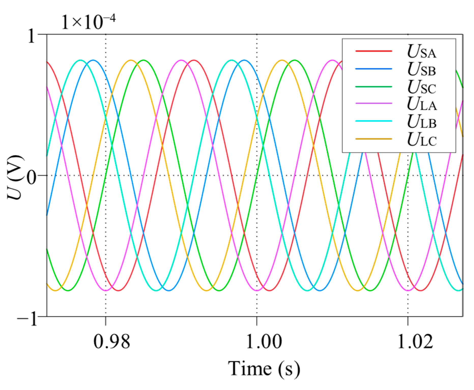
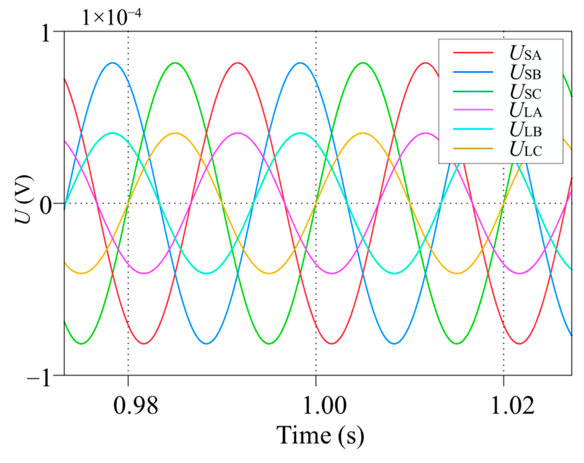
The proposed phase-shifting transformer (PST) was implemented in PLECS and evaluated on a 10 kV transmission link whose series inductance and resistance are 3 mH and 0.1 Ω, respectively. The corresponding tap-changer commands are summarized in Table 1. Figure 4 and Figure 5 highlight steady-state phase-angle and voltage-magnitude regulation, whereas Figure 6, Figure 7 and Figure 8 document dynamic power-flow adjustment following a tap change at t = 1 s.
Figure 4 illustrates the voltage waveforms obtained when the proposed phase-shifting transformer achieves a 30° phase-shift adjustment. In the plot, U ˙ S A ,   U ˙ S B ,   U ˙ S C denote the three-phase voltages before compensation, whereas U ˙ L A ,   U ˙ L B ,   U ˙ L C represent the voltages after phase-shift compensation. It can be clearly observed that the compensated voltages lead the original voltages by 30°, while their magnitudes remain stable.
Figure 5 presents the voltage waveforms corresponding to a 50% voltage-reduction adjustment achieved by the new phase-shifting transformer. By setting the turns-ratio parameters to nE1 = −0.5 and nE2 = 0, the magnitudes of the compensated three-phase voltages are equal to 50% of the original values, while the phase angles remain unchanged. This confirms the proposed topology’s ability to regulate voltage magnitude independently. The simulation shows that all three phases are uniformly regulated and that the waveform quality is preserved without noticeable distortion.
Figure 6a depicts the balanced phase voltages and highlights the instant at which the tap setting is modified; a clear phase advance is observed across all three phases. Figure 6b shows that the line currents experience a short, well-damped transient and reach a new steady state within roughly 3–5 fundamental cycles. Figure 6c traces the active-power response, revealing a smooth transition to a lower power level with minimal oscillatory behaviour, thereby confirming the effectiveness of the proposed transformer for real-time power-flow control.
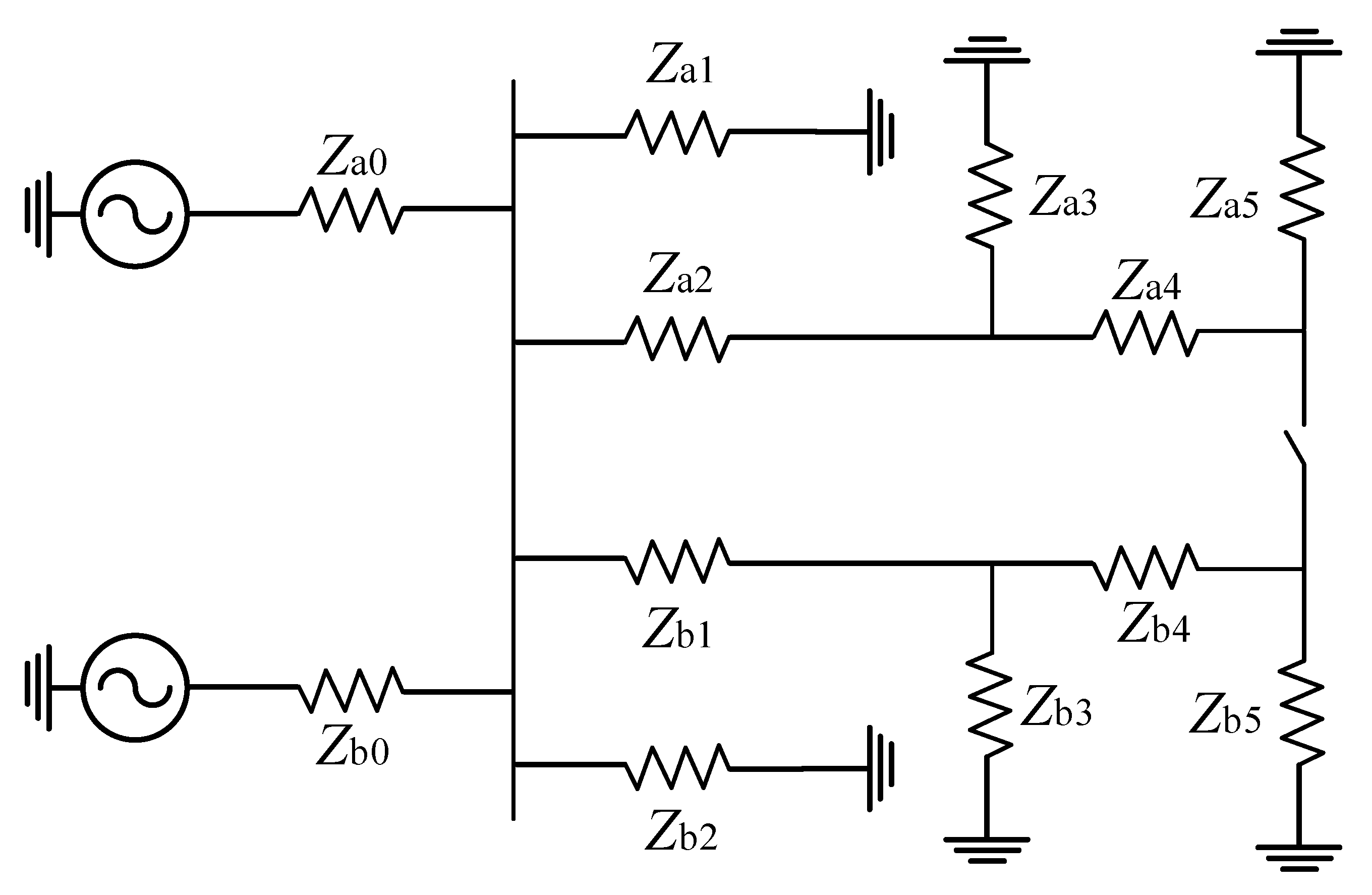
To further validate the proposed topology’s ability to suppress loop closing currents, its performance was investigated in a 220 kV transmission system model, the structure and parameters of which are based on [12], as depicted in Figure 7 and Figure 8. To simulate an adverse operating condition, a significant voltage disparity was intentionally introduced between the two subsystems: the source voltage on the ‘a’ side was set to 198 kV, while the ‘b’ side was maintained at the nominal 220 kV. The detailed equivalent impedance parameters for the feeder lines on both sides, corresponding to the model, are listed in Table 2. The parameters of PST are listed in Table 3.
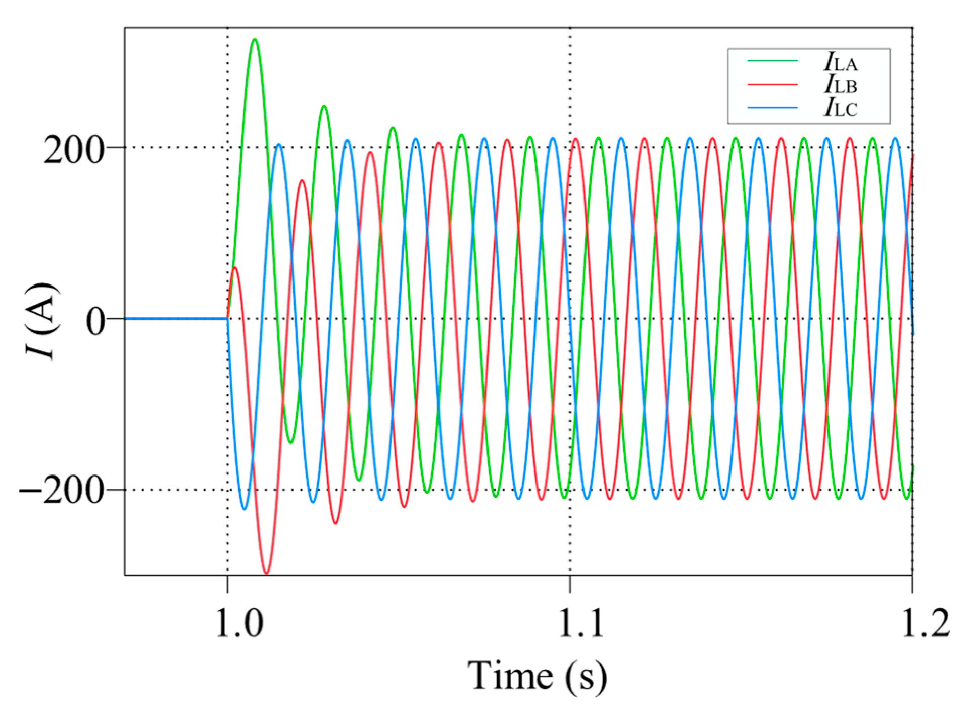
Figure 9 shows the simulation results for a direct loop closing operation at t = 1.0 s without the PST. Due to the significant pre-existing difference in voltage magnitude and phase angle between the two buses, a large loop closing current is generated, with an amplitude of approximately 200 A. Such a large loop closing current can endanger connected equipment and compromise system stability.
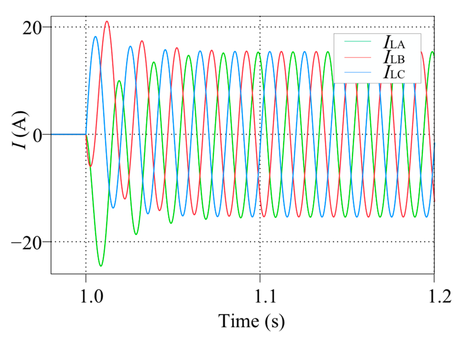
In contrast, Figure 10 illustrates the effectiveness of the proposed single-core PST. By implementing the control strategy detailed in Section 5.2, the PST pre-emptively injects a precise compensation voltage to align the phasors at both sides of the tie-switch. When the switch closes at t = 1.0 s, the loop closing current is successfully reduced to an amplitude of approximately 15 A. This represents a reduction of over 90% compared to the uncompensated case, confirming the device’s ability to ensure a secure. These findings validate the PST as a highly effective solution for managing loop closing operations, even under adverse grid conditions.
To demonstrate the robustness of the proposed method, Figure 11 presents the peak loop closing current across the entire range of possible closing phase angles. The simulation results show that the current remains consistently low, regardless of the closing instant. Even in the worst-case scenario, which occurs at a phase angle of 180°, the peak current is only approximately 24 A. This confirms that the proposed PST and its loop closing strategy effectively constrain the transient current to an acceptable range across all conditions, ensuring a secure and reliable loop closing operation.
To evaluate the impact of measurement errors in the compensation target voltage, Figure 12 presents a sensitivity analysis of the loop closing current with respect to the estimation errors in this voltage’s phase and amplitude. The results indicate that within a typical instrumentation error range (e.g., a phase error of ±5° or an amplitude error of ±2%), the loop closing current is consistently maintained below 22 A. Even under larger deviations, such as a ±15° phase error or a ±10% amplitude error, the loop closing current remains below 45 A and 32 A, respectively, showing a still-significant suppression effect compared to the uncompensated case. This demonstrates that the proposed method exhibits strong robustness and can ensure the safety of loop closing operations under practical conditions with measurement errors.

6.2. Experiment

To further verify the preceding simulation results for the loop-closing scenario, a hardware-in-loop experimental platform based on the RT-BOX and a TMS320F28379D was established, as shown in Figure 13. The experimental results corroborate the simulation findings. The oscilloscope waveform for loop-closing without the PST reveals that after the switch closes, the circuit settles to a large loop-closing current. Conversely, when the proposed PST control strategy is engaged, this loop-closing current is substantially reduced to a minimal level, as illustrated in Figure 14. These hardware-in -loop tests confirm that the proposed PST topology and its loop-closing method provide an effective and robust solution for managing loop currents in practical applications.

7. Conclusions

This study proposes a novel PST that can regulate voltage magnitude and phase angle with full decoupling, and based on this unique capability, it further designs a high-performance current suppression strategy for grid loop closing operations. Conventional SPSTs do not provide independent magnitude control, and APSTs often introduce undesired magnitude variations during phase adjustment. The proposed PST maintains decoupling, with phase changes having minimal impact on magnitude and magnitude adjustments producing negligible changes in phase angle.
Steady-state simulations confirmed that the device can adjust either variable without disturbing the other, while dynamic tests showed that line currents and active power converge rapidly whenever a tap command is issued. Furthermore, the proposed PST demonstrated exceptional performance in loop closing applications, reducing loop-closing currents by over 90% in a 220 kV network with significant voltage mismatches. The sensitivity analysis indicates that the method retains effective performance under realistic measurement and parameter uncertainties. With phasor estimation errors within ±5° for angle and ±2% for magnitude, the loop closing current remains low, and even with errors as large as ±15° or ±10%, the suppression effect remains significantly better than the uncompensated baseline.
Owing to its simple winding structure, dual-variable control capability and fast response, the proposed topology offers a cost-effective alternative to conventional FACTS equipment for applications such as power-flow balancing, renewable-energy integration, and inter-area exchanges. These results demonstrate that the new PST is a promising and economical solution for real-time power-flow control in modern transmission networks.

Author Contributions

Methodology, Y.X.; Validation, F.H.; Conceptualization, Resources, Y.D.; Writing—original draft preparation, C.B.; Writing—review and editing, X.J.; Supervision, Writing—review and editing, J.W. All authors have read and agreed to the published version of the manuscript.

Funding

This study is supported by the science and technology project of State Grid Jiangsu Electric Power Co., Ltd. (Nanjing, China), under grant J2024135.

Data Availability Statement

The original contributions presented in the study are included in the article, further inquiries can be directed to the corresponding author.

Conflicts of Interest

Author Yong Xu is employed by the company State Grid Yangzhou Power Supply Company. Authors Fangchen Huang and Yu Diao are employed by the company State Grid Yizheng Power Supply Branch Company. The remaining authors declare that the research was conducted in the absence of any commercial or financial relationships that could be construed as a potential conflict of interest. The funders had no role in the design of the study; in the collection, analyses, or interpretation of data; in the writing of the manuscript; or in the decision to publish the results.

References

  1. Jin, W.; Liu, H.; Zhang, W.; Yuan, J. Power Flow Regulation Effect and Parameter Design Method of Phase-Shifting Transformer. Energies 2024, 17, 1622. [Google Scholar] [CrossRef]
  2. Sakallıoğlu, B.; Esenboğa, B.; Demirdelen, T.; Tümay, M. Performance Evaluation of Phase-shifting Transformer for Integration of Renewable Energy Sources. Electr. Eng. 2020, 102, 2025–2039. [Google Scholar] [CrossRef]
  3. Jagtap, P.; Chandrakar, V.K. Advanced UPFC Controllers to Improve Transient and Dynamic Stability of Power System. In Proceedings of the International Conference on “Advances in Mechanical Engineering” 2023 (ICAME-2023), Nagpur, India, 22–23 December 2023. [Google Scholar]
  4. Ammr, S.M.; Asghar, M.S.; Ashraf, I.; Meraj, M. A Comprehensive Review of Power Flow Controllers in Interconnected Power System Networks. IEEE Access 2020, 8, 18036–18063. [Google Scholar] [CrossRef]
  5. Liu, J.; Hao, X.; Wang, X.; Chen, Y.; Fang, W.; Niu, S. Application of Thyristor Controlled Phase Shifting Transformer Excitation Impedance Switching Control to Suppress Short-Circuit Fault Current Level. J. Mod. Power Syst. Clean Energy 2018, 6, 821–832. [Google Scholar] [CrossRef]
  6. Brilinskii, A.S.; Badura, M.A.; Evdokunin, G.A.; Chudny, V.S.; Mingazov, R.I. Phase-Shifting Transformer Application for Dynamic Stability Enhancement of Electric Power Stations Generators. In Proceedings of the 2020 IEEE Conference of Russian Young Researchers in Electrical and Electronic Engineering (EIConRus), St. Petersburg and Moscow, Russia, 27–30 January 2020. [Google Scholar]
  7. Albrechtowicz, P.; Rozegnał, B.; Cisek, P. Comparison of Phase-Shifting Transformers Properties. Energies 2022, 15, 6224. [Google Scholar] [CrossRef]
  8. Yuan, J.; Zhang, W.; Mei, J.; Gan, D.; Zhou, H.; Zheng, Y. Independent Fast Phase Shifting Transformer: A Flexible and High-Precision Power Flow Controller. IEEE Trans. Power Deliv. 2023, 38, 4410–4421. [Google Scholar] [CrossRef]
  9. Li, J.; Lin, S.; Li, J.; Luo, Y.; Mao, C.; Li, H.; Guan, Z. Risk Assessment Method of Loop Closing Operation in Low-Voltage Distribution Network Based on Fuzzy Comprehensive Evaluation. Energy Rep. 2023, 9, 312–319. [Google Scholar] [CrossRef]
  10. Yan, X.; Peng, W.; Wang, Y.; Aslam, W.; Shao, C.; Li, T. Flexible Loop Closing Control Method for an Active Distribution Network Based on Dual Rotary Phase Shifting Transformers. IET Gener. Transm. Distrib. 2022, 16, 4204–4214. [Google Scholar] [CrossRef]
  11. Singh, P.; Tiwari, R.; Sangwan, V.; Gupta, A.K. Optimal Allocation of Thyristor-Controlled Series Capacitor (TCSC) and Thyristor-Controlled Phase-Shifting Transformer (TCPST). In Proceedings of the 2020 International Conference on Power Electronics & IoT Applications in Renewable Energy and its Control (PARC), Mathura, India, 28–29 February 2020. [Google Scholar]
  12. Zhang, N.; Chen, B.; Gao, X.; Gao, S.; Zhao, X. Modeling and Simulation of a Distribution Network with a Controllable Phase-Shifting Transformer for Loop Closing. Sci. Technol. Innov. 2024, 2, 23–26. (In Chinese) [Google Scholar]
Figure 1. Simplified model of a power system with a PST.
Energies 18 04500 g001
Figure 2. Phasor representation of PST voltage injection in a three-phase system.
Energies 18 04500 g002
Figure 3. Structure of the proposed single-core PST.
Energies 18 04500 g003
Figure 4. Voltage Waveforms with 30° Phase-Shift Regulation.
Energies 18 04500 g004
Figure 5. Voltage waveforms with 50% voltage magnitude reduction.
Energies 18 04500 g005
Figure 6. Dynamic regulation waveforms obtained with the proposed phase-shifting transformer: (a) three-phase voltages before and after the tap-ratio change applied at t = 1.0 s; (b) transient response of the three-phase line currents; (c) active-power variation during the regulation process.
Energies 18 04500 g006
Figure 7. Simulation model for direct loop closing in the 220 kV network without the PST.
Energies 18 04500 g007
Figure 8. Simulation model for loop closing in the 220 kV network with the proposed PST installed.
Energies 18 04500 g008
Figure 9. Loop closing current waveform at t = 1.0 s without PST compensation.
Energies 18 04500 g009
Figure 10. Reduced loop closing current waveform at t = 1.0 s with the proposed PST.
Energies 18 04500 g010
Figure 11. Peak loop closing current at different closing phase angles.
Energies 18 04500 g011
Figure 12. Sensitivity analysis of measurement errors in the compensation target voltage: (a) Effect of phase error on loop closing current; (b) Effect of amplitude error on loop closing current.
Energies 18 04500 g012
Figure 13. Hardware-in-loop experimental platform.
Energies 18 04500 g013
Figure 14. Experimental waveforms of loop closing current: (a) current waveform without PST compensation; (b) current waveform with PST compensation.
Energies 18 04500 g014
Table 1. Parameters of transformer ratio settings.
FigurenE1nE2
Figure 3−0.423−0.577
Figure 4−0.50
Figure 5−0.736 → −0.288−0.841 → −0.431
Table 2. Equivalent Impedance Parameters of the Feeder Lines.
Feeder Line of Side aEquivalent Impedance/ΩFeeder Line of Side bEquivalent Impedance/Ω
Za010 + j0.314Zb010 + j0.314
Za112.03 + j2.450Zb13.50 + j1.018
Za20.10 + j0.603Zb20.05 + j0.302
Za38.60 + j2.752Zb316.24 + j2.714
Za40.05 + j0.302Zb40.03 + j0.151
Za510.64 + j2.224Zb58.06 + j2.865
Table 3. Parameters of the PST.
Parameter of PSTValue
Leakage inductance of primary windings (mH)2.56
Leakage inductance of secondary windings (mH)0.64
Primary winding resistance (Ω)0.0805
Secondary winding resistance (Ω)0.0202
Magnetizing curve (T, A/m)(0, 0), (0.2, 12), (0.4, 24), (0.6, 38), (0.8, 55), (1.0, 80),
(1.2, 120), (1.4, 200), (1.6, 430), (1.7, 800), (1.8, 2000)
Rated Capacity (MVA)400
Disclaimer/Publisher’s Note: The statements, opinions and data contained in all publications are solely those of the individual author(s) and contributor(s) and not of MDPI and/or the editor(s). MDPI and/or the editor(s) disclaim responsibility for any injury to people or property resulting from any ideas, methods, instructions or products referred to in the content.