Article

Large Temperature Difference Heat Pump System for Long-Distance Heat Transportation: Experimental Study and Feasibility Analysis

by
Qing Miao
1,
Minxia Li
1,*,
Chaobin Dang
2,*,
Beiran Hou
1 and
Shigang Zhang
3
1
State Key Laboratory of Engines, Tianjin University, Tianjin 300072, China
2
Graduate School of Engineering, University of Fukui, Fukui 910-8505, Japan
3
Beijing Qingjian Energy Technology Co., Ltd., Beijing 100084, China
*
Authors to whom correspondence should be addressed.
Energies 2025, 18(16), 4449; https://doi.org/10.3390/en18164449
Submission received: 11 May 2025 / Revised: 30 July 2025 / Accepted: 14 August 2025 / Published: 21 August 2025
(This article belongs to the Special Issue Advances in Refrigeration and Heat Pump Technologies)

Abstract

With the increasing depletion of fossil fuels, it is urgent to build an efficient regional heating scheme. Long-distance heating transportation schemes are important for the integration and utilization of low-grade heat resources. It is worth noting that when implementing the long-distance heating transportation scheme, a heat pump system with large temperature differences and high flexibility is required. However, the conventional vapor compression heat pump system is generally based on a single-stage cycle construction, which has the problems of poor heating capacity and a narrow operation range. In this study, a novel large temperature difference heat pump system is proposed. The heat transfer process of the novel heat pump system is serrated, and the pressure ratio of the compressor is similar under different working conditions. Through experimental study, the energy efficiency performance of the system is explored. Taking the conventional heat pump as the comparison object, the annual performance of the system is analyzed. The results show that the novel system can reduce carbon emissions and operation costs by more than 50%.

1. Introduction

Burning fossil fuels is a key driver of global warming, while conventional heating systems rely mainly on coal-fired and gas-fired boilers [1]. In China, about 210 million tons of standard coal equivalent are used for district heating, accounting for about 5% of total energy consumption [2]. Therefore, developing green, highly efficient, and adaptable heating technology has become an urgent task [3]. The district heating process is characterized by its large energy demand, but the requirement for energy grade is relatively low [4]. For example, the operation temperature range of the hot water heat exchanger for building heating is usually 40~60 °C [5]. It is worth noting that the temperature of low-grade heat resources, such as waste heat in power plants and geothermal heat, is about 30~100 °C [6]. Suppose such low-grade heat resources could directly or indirectly be integrated into the district heating system. In that case, it would be expected to reduce the energy consumption in the district heating process significantly.
Although relying on waste heat for district heating has many advantages, its application still faces some problems. The primary problem is that the distribution of waste heat resources is relatively scattered, and the distance between the end users is far, resulting in the high cost of long-distance heat transportation [7]. To solve the above problems, large temperature difference district heating technology is widely used [8]. The large temperature difference in district heating technology increases the temperature of low-grade waste heat by adding a heat pump system to realize long-distance transmission [9]. Additionally, the pipe network’s heating capacity and range are enhanced by increasing the temperature difference between the supply and return waters.
At present, the large temperature difference heating system is generally based on an absorption heat pump [10]. For example, Li et al. [11] constructed a mathematical model of a substation with two absorption heat pumps and two heat exchangers. The results show that the COPh of the system can reach 6.6. Yi et al. [12] constructed an absorption heat pump system with three independent temperature regions. The results show that the energy-saving rate of the system can reach 12.4%. However, the absorption heat pump is bulky and difficult to install, and it is difficult to adapt to the comprehensive transformation of the old heating system [13]. In addition, the initial investment in an absorption heat pump is high, and operation and maintenance are difficult [14]. Therefore, constructing a more flexible long-distance district heating scheme is worth considering.
Compared with absorption heat pump, vapor compression heat pump technology is more mature [15]. The vapor compression heat pump is driven by electricity, compressing the low-temperature refrigerant into high-temperature gas and releasing heat in the condenser. The advantages of vapor compression heat pumps include a simple structure, small volume, and low initial investment costs. [16]. Currently, it is widely used in the field of low-grade waste heat recovery. For example, Zhou et al. [17] applied CO2 mixed refrigerant to a vapor compression heat pump to recover waste heat from wastewater, and the COPh of the system reached 7.46. Zhang et al. [18] applied vapor compression heat pump systems to data center waste heat recovery. The results show that the comprehensive COPh of the system can reach 7.0. Liu et al. analyzed the influence of the working fluid selection scheme on a high-temperature waste heat recovery heat pump. The results show that the mixture of CO2, R600a, and R1233zd (E) performs better [19]. Obika et al. [20] demonstrated a R245fa/R1233zd(E) mixture heat pump achieving COP 2.7 with 80 °C temperature lift, producing 140–170 °C hot water while reducing compressor power by 3.9% versus standard working fluids systems. Feng et al. [21] implemented screw-type EG-ZnO/glycol heat pumps in glass factories, recovering 20 °C waste heat to generate 45 °C heating water, saving 158 t standard coal/season (400 t CO2 reduction). Transcritical CO2 cycles with ejector expansion have become prevalent in high-temperature drying, optimizing industrial waste heat utilization through pressure-energy conversion [22].
In long-distance district heating systems, the significant temperature difference between the supply and return water circulating through the heating units creates technical challenges [23]. Conventional single-stage vapor compression heat pumps typically have a maximum outlet water temperature drop of around 5 °C [24]. As system temperature differentials increase, single-stage heat pump compressors must operate at higher pressure ratios. Excessive pressure ratios can significantly reduce compressor efficiency and operational longevity [25]. In addition, the load fluctuation in the long-distance heating process is large, and the adjustment ability of the heat pump system aiming at building heating makes it difficult to meet the demand of load fluctuation [26]. Thus, how to build a district heating scheme with large temperature differences and high flexibility based on vapor compression heat pump technology is an urgent problem to be solved.
To solve the above problems, a novel large temperature difference heat pump system is proposed in this study. The novel system consists of a multi-stage heat pump system, and different heat pumps are connected in series. To ensure efficient and stable operation, the heat transfer process between the system and the heating pipe network is serrated, and the operation pressure ratios of compressors in different systems are similar. In addition, based on the operation characteristics of the system, the full-condition control strategy of the novel system is proposed. The experimental study method is adopted to explore the feasibility of the system. Further, based on the actual district heating project, the conventional heat pump system is selected as the comparison object, and the feasibility of the system is analyzed. The results show that the annual operation cost and carbon emissions of the novel system can be reduced by more than 50%. This study aims to provide a theoretical basis for long-distance heat transportation and give a feasible optimization scheme.
Unlike conventional vapor compression heat pumps, this study distinguishes itself through its integration with large-temperature-difference, long-distance heating systems. Unlike traditional decentralized applications, the system uses a centralized heating mode coupled with district heating networks. This configuration enables greater temperature lift/drop capacity, a broader operational range, and more frequent load-variation cycles.

2. Proposal of the Novel System

The principle of the conventional single-stage heat pump system is shown in Figure 1. To meet the demand of heating demand, the temperature difference in the heat exchanger of the conventional heat pump system is large, and the irreversible loss is large. Furthermore, the compressor must operate at high-pressure ratios to achieve the required supply and return water temperature difference. As a result, single-stage heat pump compressors for large temperature differentials have high exhaust temperatures, making it difficult to cool the compressor motor—multiple factors, including user demand and meteorological parameters, influence operation conditions. In contrast, the adaptability of the single-stage heat pump system is quite limited. For example, multi-compressor parallel single-stage heat pump systems must prioritize oil balancing among compressors, and variable-frequency single-stage heat pump systems have a narrow optimal operation range for their compressors. Generally, conventional single-stage heat pump systems struggle to meet the demands of large temperature differences and long-distance heating.
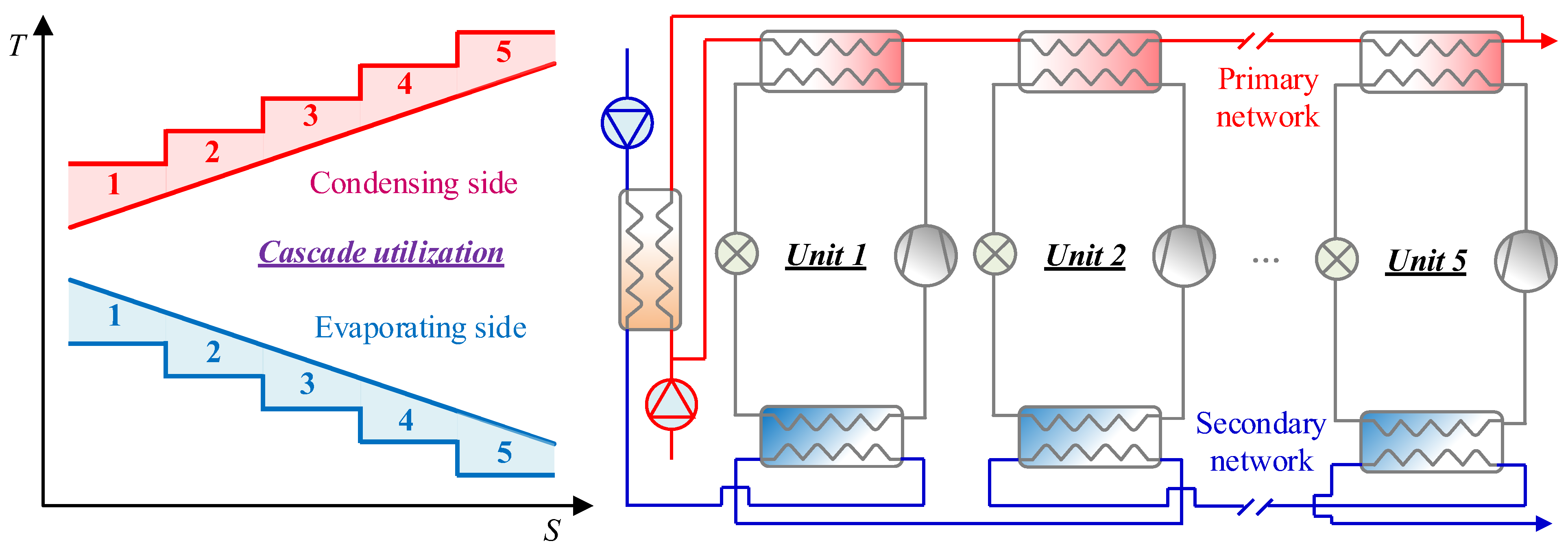
To solve the above problems, a novel system for large temperature differentials and district heating is developed in this study, as shown in Figure 2. The system consists of multi-stage temperature-raising units, with the primary network flowing through the condensing side of each heat pump system, and the secondary network flowing through the evaporating side. A multi-stage series design is used to improve energy efficiency. During operation, the condensing temperatures of different module systems vary. The refrigerant–water heat exchange process is zigzag-shaped, which allows a stepwise utilization of the evaporating and condensing temperatures, thereby reducing irreversible losses in the heat exchange process. To improve the flexibility of the novel system, the heat pumps use compressors with different pressure ratios at each stage, with each stage operating independently. When the external loads change significantly, the system adjusts the operation stages of the units based on a final stage load modulation strategy, ensuring compressors at all stages of the system can operate within their optimal operation ranges.

3. Design of Experiment

3.1. Design of Experiment Platform

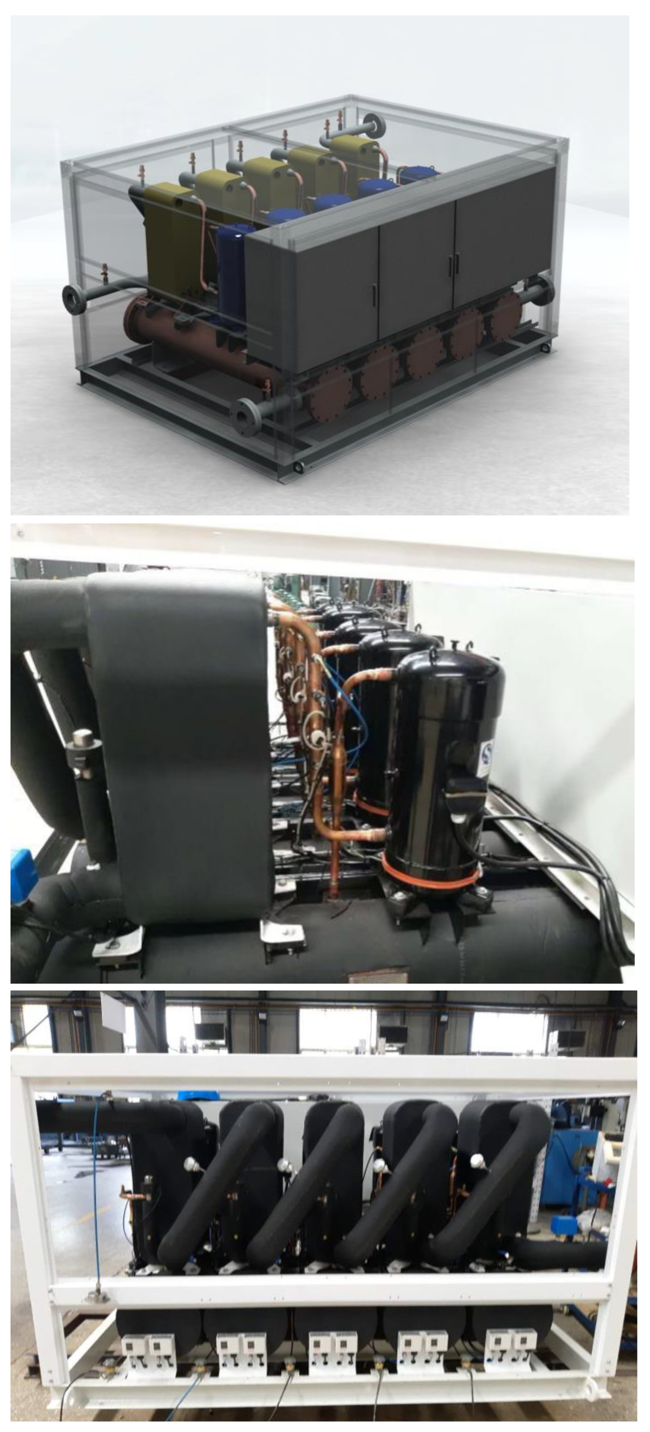
In this study, an experimental study is conducted to verify the feasibility of the novel system. In most cases, maintaining the return water temperature within the range of 40–60 °C is sufficient to meet heating demands [27]. A typical return water temperature of 45 °C is selected for the secondary network. After accounting for the temperature difference in the heat exchange terminal of the water-to-water heat exchanger, the resulting inlet water temperature on the evaporator side of the unit is determined to be 48 °C. So the key conditions are designed as follows: (1) On the evaporating and condensing sides, the flow rates are set at 6.2 m3/h, respectively, the inlet water temperature is 48 °C, and the outlet temperature is 15 °C on the evaporating side. The inlet water temperature is 45 °C and the outlet temperature is 60 °C on the condensing side. (2) The terminal temperature differences between the evaporator and the condenser are maintained at 3 °C, superheat is set to 5 °C, and condenser subcooling is set to 5 °C. (3) The water temperature difference on both sides of the first-stage heat pump remains constant at 3 °C. The key components of the unit include a compressor, evaporator, condenser, expansion valve, etc. The structural parameters of the main components are shown in Table 1. The systematic experimental platform is shown in Figure 3.

3.2. Design of Experiment Scheme

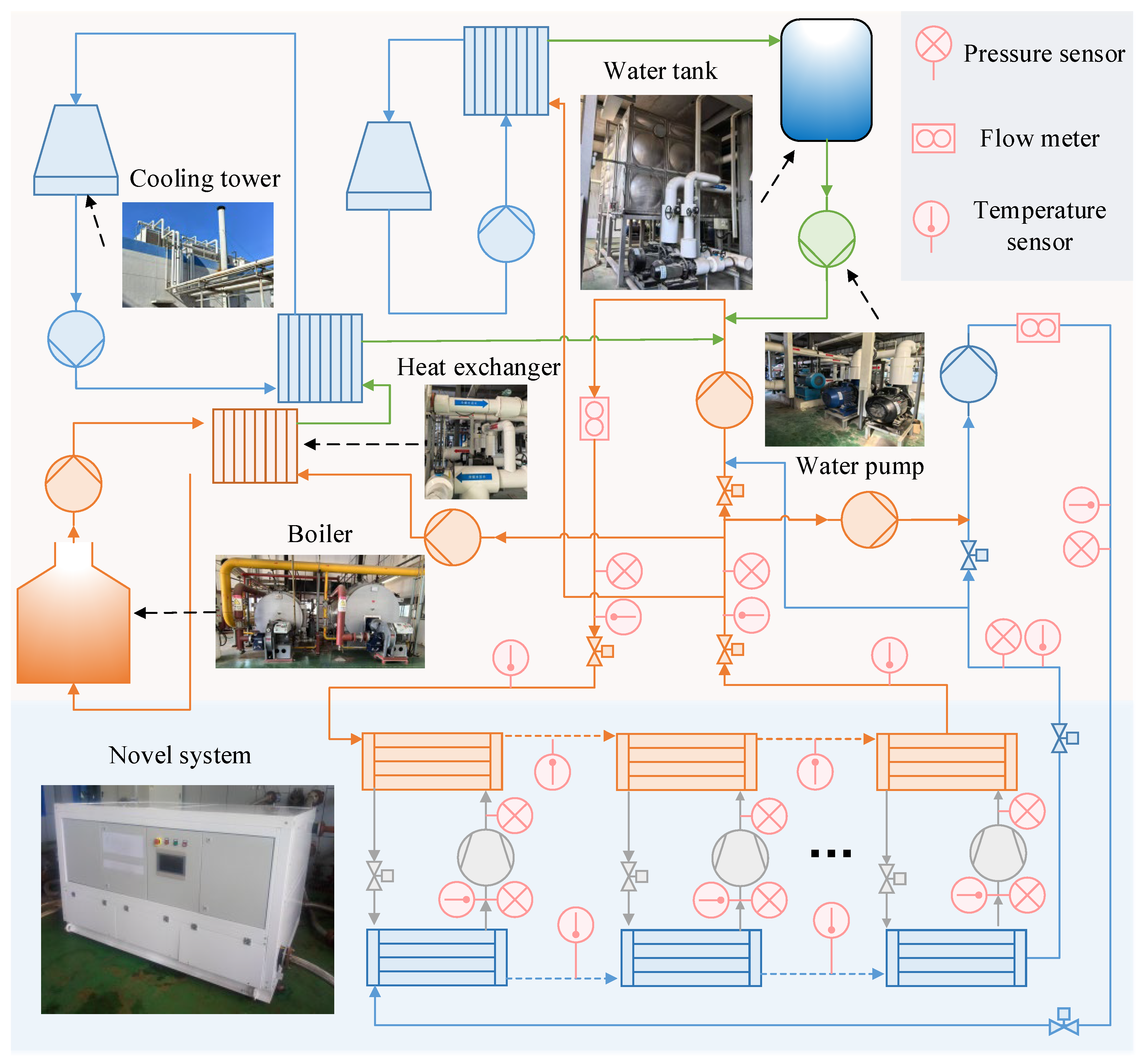
As shown in Figure 4, the experimental platform integrates key components such as heat source simulation circulation piping, user simulation circulation piping, cooling system, auxiliary heating system, constant temperature water tank, control cabinet, and data acquisition system. The main types of operation data include evaporating pressure, condensing pressure, supply water temperature, return water temperature, etc. The main sensor types and their accuracy are listed in Table 2. The control processes of the main system components and the data acquisition are carried out by the PLC (Programmable Logic Controller) operation and maintenance platform.
During the experimental process, the primary and secondary water networks are connected to the corresponding pipes of the experimental setup, and the control system is used to set the water flow rate and temperature to predetermined values. Then, auxiliary equipment such as the mixing water piping, cooling tower, or electric boiler on the experimental setup is activated to achieve a reasonable allocation and supplement of energy. Meanwhile, a constant-temperature water tank is used to maintain stable water temperatures and ensure the reliability of the experimental environment. Finally, the heat pump units are sequentially activated. Once the system has stabilized, key operation parameters are recorded. In addition, different operation conditions are simulated by adjusting the input parameters to evaluate the performance comprehensively. The calculation formula for system energy efficiency performance is as follows:
C O P = c we m we ( T w i e T w o e ) W com 1 + W com 2 + W com 5
where cwe is the water-specific heat capacity in the evaporator, kJ/(kg·K); Twie is the inlet water temperature in the evaporator, °C; Twoe is the outlet water temperature in the evaporator, °C; and mwe is the volume flow rate of water in the evaporator, kg/s. Wcom is the power consumption of different compressors.
The calculation formula for the heating energy efficiency performance of the system is as follows:
C O P h = c wc m wc ( T w o c T w i c ) W com 1 + W com 2 + W com 5
where cwc is the condenser water-specific heat capacity, kJ/(kg·K); Twic is the condenser inlet water temperature, °C; Twoc is the condenser outlet water temperature, °C; and mwc the condenser volume flow rate of water, kg/s. Wcom is the power consumption of different compressors.
This experimental system is designed in compliance with the GB/T 10870-2014 standard [28]. According to the test uncertainty calculation method in Appendix E of this standard, it can be calculated by Equation (3):
w f = 1 n f x i w x i 2
where wxi is the uncertainty of direct measurement parameters, where the COPh’s uncertainty of system is less than 2%.

4. Experimental Results

The following key parameters are used in the operation of the novel system: water flow rates on the evaporator (mwe) and condenser (mwc) sides, and inlet and outlet water temperatures for both sides. The outlet temperature of the primary network (Twoe) depends on user demand. The inlet temperature of the secondary network (Twic) changes due to end-user load during heating seasons. In terms of water flow rates, the flow rate of the primary network is determined by the design cooling capacity of the unit. To control the efficiency and resistance of the heat exchanger within the design range, the flow rate of the secondary network is kept constant. The ratio of flow rates between the two networks (mwc/mwe), related to heating demand, can vary slightly by project. The novel system is equipped with multiple compressors, and the number of compressors opened may also affect system performance.

4.1. Influence of Inlet Water Temperature of Secondary Network

The variation in the COP with the return water temperature (Twic) in the secondary network is shown in Figure 5. As the return water temperature (Twic) in the secondary network increases, the COP for systems of different stages all show a downward trend. As Twic increases from 39.2 °C to 48 °C, the COP of a 5-stage heat pump decreases by 10%, and the COP of a 1-stage heat pump decreases by 9%. On average, for every 1 °C rise in Twic, the COP decreases by 1%. In general, the variation in Twic has a relatively small impact on the COP. In practical applications, Twic is related to the difference between the heating parameters of the project and the fluctuation of the external ambient temperature. However, typically, its fluctuation range is within 30~50 °C. Therefore, under normal operation conditions, the COP of the unit will fluctuate slightly, and the system will be able to adapt to different scenarios.
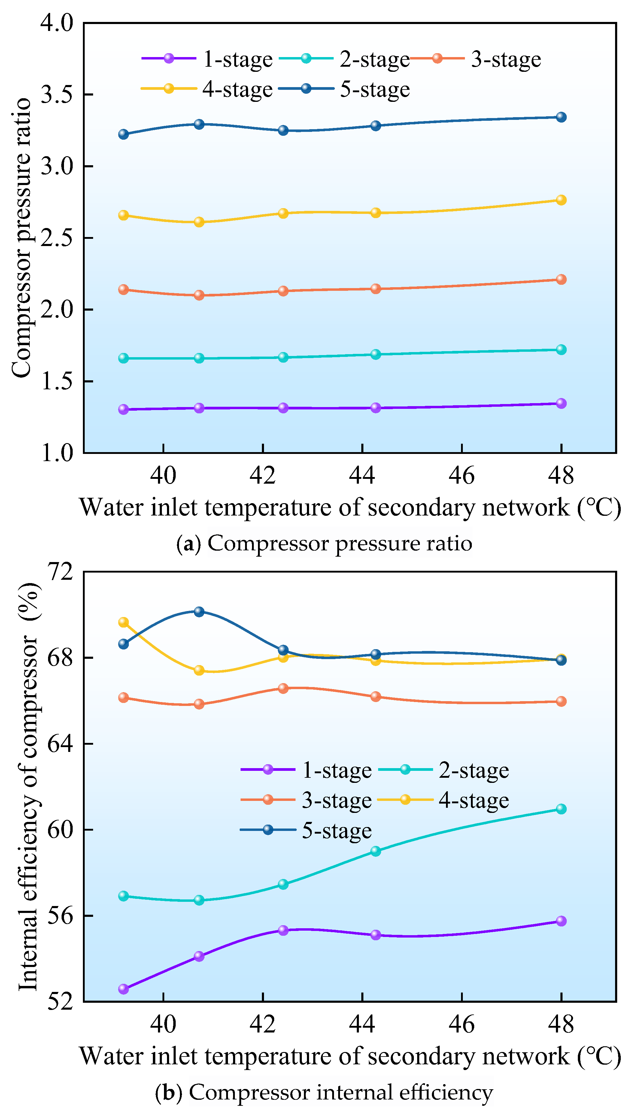
The compression ratio is the main operational parameter affecting the internal efficiency of the displacement compressor. Figure 6a shows the change in the compression ratio of each heat pump under different working conditions. With the increase in Tco, the compression ratio of each compressor is on the rise. When Tco increases from 39.2 °C to 48 °C, the pressure ratio change of the 5-stage heat pump is less than 10%, and the pressure ratio change of the 1-stage heat pump is less than 9%. As shown in Figure 6b, the fluctuation range of the 1-stage and 2-stage is less than 7%, and the fluctuation range of efficiency in stage 3–5 compressors is less than 2%. It can be seen that the internal efficiency of different unit compressors is always maintained at a high level. In this way, the COP of the novel system can maintain a high level over a wide temperature fluctuation range.

4.2. Influence of Water Flow Ratio

Figure 7 illustrates the relationship between flow rate ratio (mwc/mwe) and system performance. As the flow ratio increases from 2.64 to 3.85, the COP of the system shows an upward trend at different water temperature drops of the primary network (ΔTwp). Specifically, when ΔTwp is set to 7.2 °C, the COP increases from 12.2 to 13.5, whereas in the case of ΔTwp being 31.4 °C, the COP rises from 5.2 to 5.7. When the flow ratio is increased by 46%, the COP of the system is increased by about 10%. Furthermore, the increase in the COP of the unit concerning the evaporator inlet temperature difference is similar in proportion at different flow ratios. It is mainly attributed to the relatively large temperature difference on the evaporator side of the unit under rated conditions (approximately 33 °C). In addition, the water temperature rise on the condensing side is relatively small (approximately 15 °C). When the flow ratio increases from 2.64 to 3.85, the temperature difference on the condensing side decreases from 15 °C to 10 °C, which only accounts for 11.6% of the total temperature difference (48 °C) between the two sides. That is to say, the flow ratio has a relatively minor effect on the COP.

4.3. Influence of Control Strategy

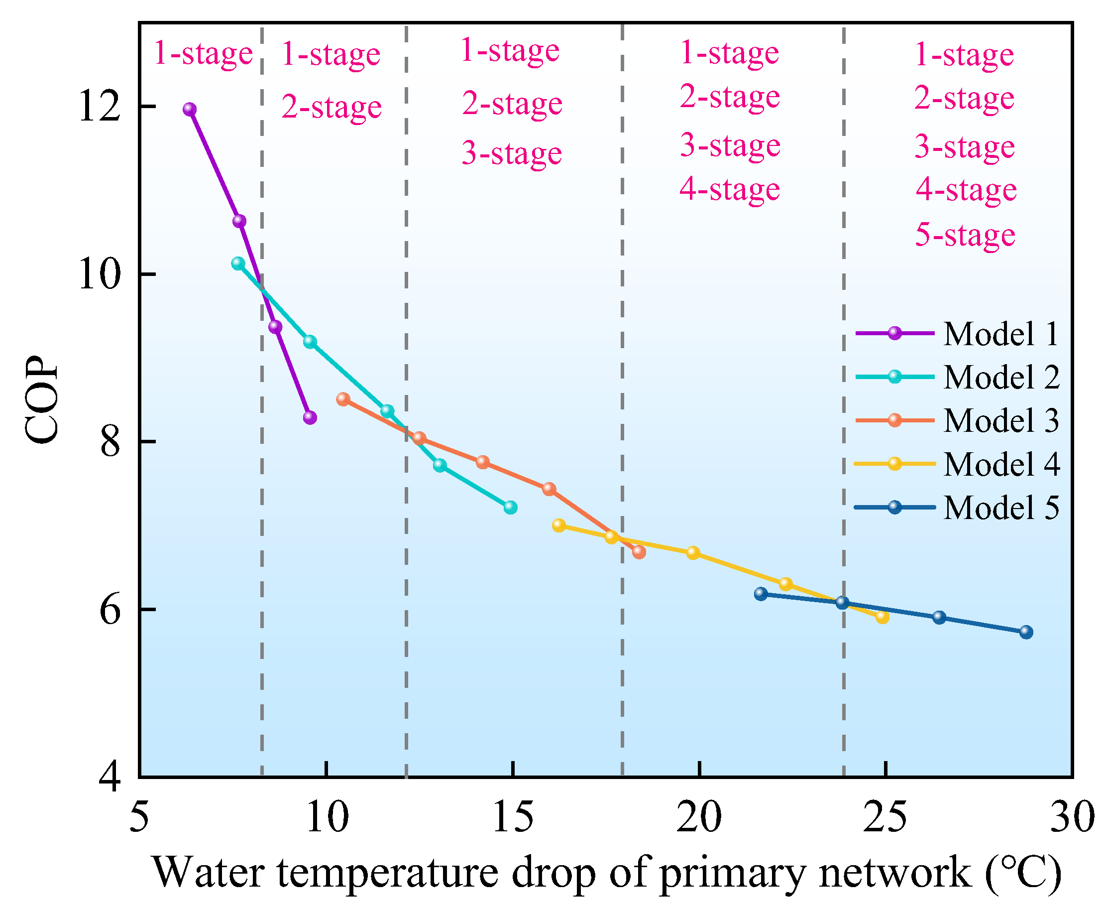
The changing trend of unit opening count and performance with load demand is shown in Figure 8. From the perspective of the heat transfer process, the more the number of stages of the heat pump system is opened, the smaller the total heat transfer temperature difference of the system and the smaller the irreversible loss. However, the operation conditions of the compressor also affect the COP. For example, when the primary network temperature drops to 7.5 °C, the COP is reduced by 3.9% when the second stage is turned on compared with the single-stage operation. This is because the design optimization of the compressor is usually aimed at a specific operation point, which is difficult to adapt to all the changing operation conditions throughout the year. If the compression ratio seriously deviates from the design value, it will affect the service life of the compressor. Therefore, each heat pump module should be opened according to the load in the system operation process. The switching temperatures of the system are 8.1 °C, 12.1 °C, 17.9 °C, and 23.9 °C.

5. Feasibility Analysis

5.1. Application Site and Comparison Object

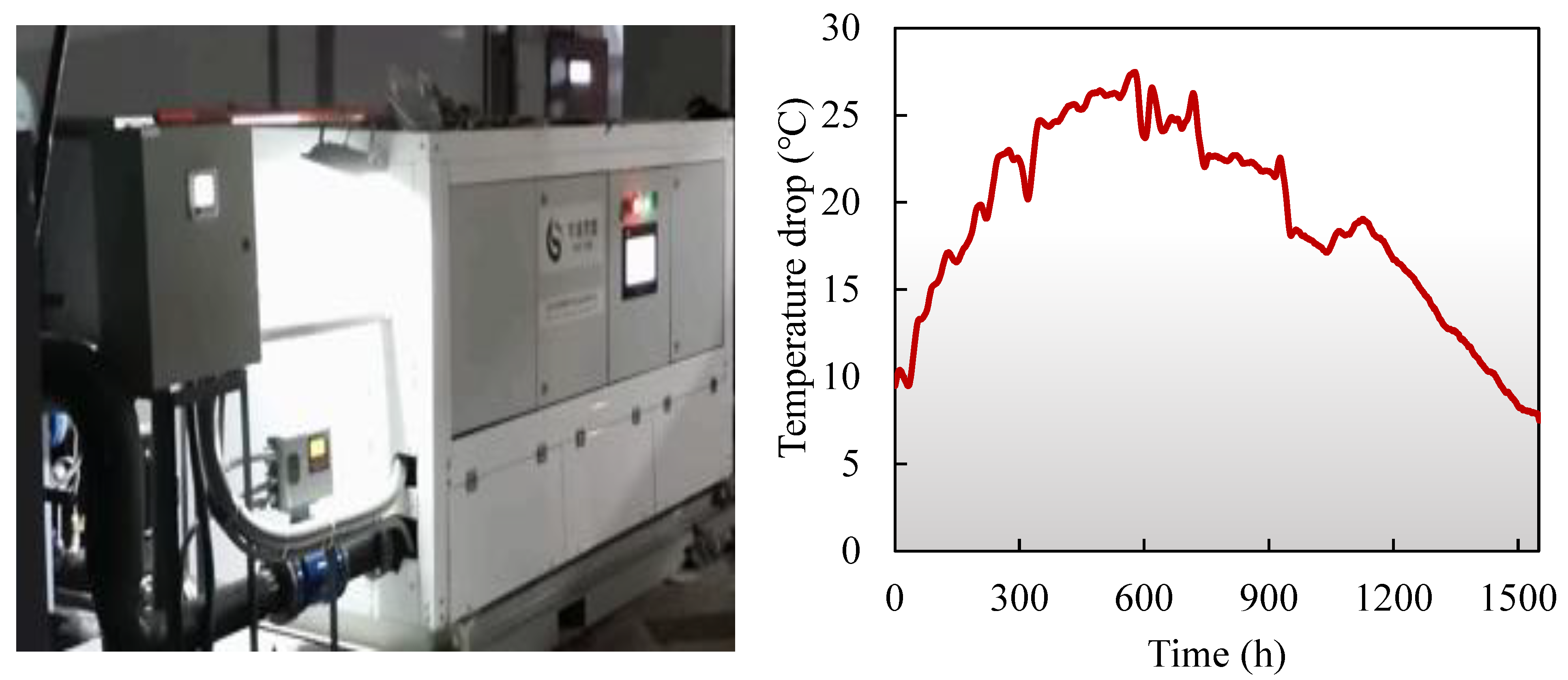
To explore the feasibility of the novel system, this study selects a heat exchange station in Hejin City. Hejin is located in the west of North China and the southwest of Shanxi Province. The rated water supply capacity of the heat exchange station is 15 T/h, and its heating area is approximately 3000 m2. As shown in Figure 9, the heat exchange station has a single-stage water source heat pump heating system. Due to meteorological conditions, the heating load of the system during the heating season increases initially and then decreases as the operation time increases. The maximum heating load exceeds 500 kW, and the maximum outlet water temperature difference is higher than 25 °C. The design stage is set as five. But as the environmental temperature changes, the unit’s load will also change accordingly. The demand for the water temperature drop of the unit varies. Accordingly, the number of operating stages will also change.
To conveniently estimate the unit’s annual operating efficiency and cost, Formula (4) can be derived by testing and regressing the (COPhc) of conventional single-stage compressors under various temperature drops.
C O P hc = 0.00006 ( Δ T wp ) 3 +   0.0064 ( Δ T wp ) 2 0.2402 Δ T wp + 6.7171
Similarly, the correlation between the (COPhn) of large-temperature-difference units and different temperature drops can be obtained.
C O P hn = 0.001 ( Δ T wp ) 3 + 0.0689 ( Δ T wp ) 2 1.6036 Δ T wp + 20.359

5.2. Environmental and Economic Analysis

The system’s hourly carbon emissions from power consumption are determined using Equation (6):
E power = 3600 × F power × W
Here, Epower represents the carbon emissions per hour (kg/h), W denotes the system’s average hourly energy consumption (kW), and Fpower stands for the electricity carbon emission factor (kg/kWh). As Shanxi falls under the North China Power Grid, the Fpower value is set at 0.84 kg/kWh. Equation (7) is employed to compute the system’s hourly electricity cost:
C power = 3600 × Z power × W
where Zpower indicates the electricity price (CNY/kWh) and W remains the system’s average hourly energy consumption (kW). Table 3 provides the time-of-use electricity pricing data for Hejin.
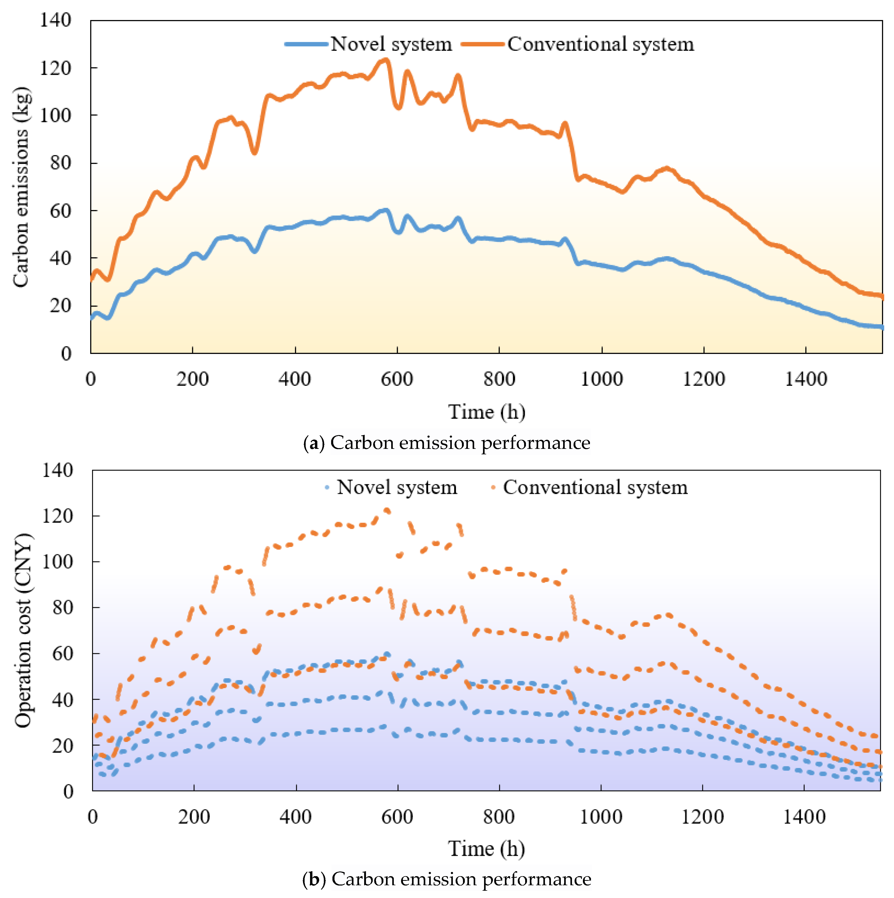
The hourly carbon emissions of both the conventional system and the novel system are shown in Figure 10. The novel system shows a higher emission reduction efficiency under high load conditions, achieving a maximum reduction of 63 kg of carbon emissions per hour. It is attributed to the greater temperature difference across the heat exchange process under high load conditions. The novel system can achieve cascade heating by increasing the number of operation stages, thereby reducing the system’s irreversible losses. From a yearly perspective, the total carbon emissions during the heating season for the conventional system are 121,405 tons, while the total carbon emissions during the heating season for the novel system are 60,625 tons. In Figure 10b, the three lines in the figure represent the operating costs of the units during the power grid’s peak, off-peak, and sub-off-peak periods, respectively. Unlike the environmental performance, the operation costs of the different systems vary significantly throughout the day due to peak and off-peak electricity pricing policies. From an annual perspective, the average COPh for the conventional system during the heating season is 4.13, with a total operating cost of CNY 88,917. In contrast, the average COPh and total operating cost for the novel system during the heating season are 8.3 and CNY 44,402, respectively. It can be seen that the novel system has reduced both carbon emissions and operation costs by approximately 50% compared to the conventional system.

6. Conclusions

This study provides experimental validation of the feasibility of using electric vapor compression heat pumps in large temperature difference district heating systems. Through systematic testing, we identified the operational characteristics and the regressed COP equations from the experimental data. Based on these equations, a comparative analysis was conducted with conventional heat pump systems in terms of operation cost and carbon emissions. Key findings include the following:
(1)
Primary water temperature drop has the most significant impact on system performance.
(2)
Flow rates of both primary/secondary water and secondary water temperature drop have negligible effects.
(3)
COP decreases by approximately 1% for every 1 °C reduction in secondary water temperature.
(4)
The system has an optimal control strategy. As the temperature difference of the primary network increases, the system should open each heat pump module step by step.
(5)
Compared with the scheme using the single-stage heat pump system, the carbon emissions and operation costs of the scheme using the novel system can be reduced by more than 50%.
(6)
The increasing use of renewable energy sources has led to greater uncertainty in electricity pricing and carbon emission factors, raising concerns about the feasibility of the system.

Author Contributions

Q.M.: Conceptualization, data curation, formal analysis, investigation, methodology, software, validation, writing—original draft preparation, visualization; M.L.: Conceptualization, project administration, resources, writing—review and editing; C.D.: Conceptualization, funding acquisition; B.H.: visualization, writing—review and editing; S.Z.: Conceptualization, resources, funding acquisition. All authors have read and agreed to the published version of the manuscript.

Funding

This research was supported by JSPS Grant-in-Aid for Scientific Research (C) Grant (NO. 20K04320), JKA, through its promotional funds from KEIRIN RACE (2023M-372), and The Iwatani Naoji Foundation.

Data Availability Statement

The original contributions presented in this study are included in the article. Further inquiries can be directed to the corresponding authors.

Conflicts of Interest

Author Shigang Zhang was employed by the Beijing Qingjian Energy Technology Co., Ltd. The remaining authors declare that the research was conducted in the absence of any commercial or financial relationships that could be construed as a potential conflict of interest.

Nomenclature

The following abbreviations are used in this manuscript:
cwcWater-specific heat capacity in the condenser, kJ/(kg·K)
cweWater-specific heat capacity in the evaporator, kJ/(kg·K)
CpowerHourly power cost, CYN/h
COPCoefficient of performance of refrigeration system
COPhCoefficient of performance of heat pump system
EpowerHourly electricity carbon emissions, kg/h
FpowerCarbon emissions from electricity, kg/kWh
mwcMass flow rate of water in the condenser, kg/s
mweMass flow rate of water in the evaporator, kg/s
TwicInlet water temperature in the condenser, °C
TwocOutlet water temperature in the condenser, °C
TwieInlet water temperature in the evaporator, °C
TwoeOutlet water temperature in the evaporator, °C
ΔTwpWater temperature drop of primary network, °C
WcomEnergy consumption of the compressor, kW
ZpowerPower price, CNY/kWh

References

  1. Ermel, C.; Bianchi, M.V.A.; Cardoso, A.P.; Schneider, P.S. Thermal Storage Integrated into Air-Source Heat Pumps to Leverage Building Electrification: A Systematic Literature Review. Appl. Therm. Eng. 2022, 215, 118975. [Google Scholar] [CrossRef]
  2. Zhang, Y.; Zheng, W.; Fang, H.; Xia, J. Clean Heating in Northern China: Regional Investigations and Roadmap Studies for Urban Area Towards 2050. J. Clean. Prod. 2022, 334, 130233. [Google Scholar] [CrossRef]
  3. Zheng, Z.; Zhou, J.; Xu, F.; Deng, G. Solar Assisted Air Source Heat Pump Systems for Campus Water Heating in China: Economic Optimization of Solar Fraction Design. Appl. Therm. Eng. 2022, 213, 118767. [Google Scholar] [CrossRef]
  4. Lu, Y.; Yu, M.; Yu, J. Performance Analysis of Dual Ejector-Expansion Air Source Heat Pump Cycle with Three-Stage Evaporation for Cold Region Application. Appl. Therm. Eng. 2023, 226, 120259. [Google Scholar] [CrossRef]
  5. O’Hegarty, R.; Kinnane, O.; Lennon, D.; Colclough, S. Air-to-Water Heat Pumps: Review and Analysis of the Performance Gap Between In-Use and Product Rated Performance. Renew. Sustain. Energy Rev. 2022, 155, 111887. [Google Scholar] [CrossRef]
  6. Guo, F.; Zhu, X.; Li, P.; Yang, X. Low-Grade Industrial Waste Heat Utilization in Urban District Heating: Simulation-Based Performance Assessment of a Seasonal Thermal Energy Storage System. Energy 2022, 239, 122345. [Google Scholar] [CrossRef]
  7. Fang, H.; Xia, J.; Zhu, K.; Su, Y.; Jiang, Y. Industrial Waste Heat Utilization for Low Temperature District Heating. Energy Policy 2013, 62, 236–246. [Google Scholar] [CrossRef]
  8. Fu, L.; Li, Y.; Wu, Y.; Wang, X.; Jiang, Y. Low Carbon District Heating in China in 2025—A District Heating Mode with Low Grade Waste Heat as Heat Source. Energy 2021, 230, 120765. [Google Scholar] [CrossRef]
  9. Li, Y.; Pan, W.; Xia, J.; Jiang, Y. Combined Heat and Water System for Long-Distance Heat Transportation. Energy 2019, 172, 401–408. [Google Scholar] [CrossRef]
  10. Xie, X.; Jiang, Y. Absorption Heat Exchangers for Long-Distance Heat Transportation. Energy 2017, 141, 2242–2250. [Google Scholar] [CrossRef]
  11. Li, T.; Chen, W.; Li, X.; Wang, B.; Shi, W. Investigation of Control Strategies for Dual-Temperature District Heating Substations with Two Absorption Heat Pumps and Two Heat Exchangers. Energy Convers. Manag. 2024, 309, 118431. [Google Scholar] [CrossRef]
  12. Yi, Y.; Xie, X.; Jiang, Y.; Sun, M.; Yang, E. Process Design, Performance Comparison and Operating Test of the Multi-Stage Vertical Absorption Heat Exchanger Realizing Independent Heating in Three Zones. Appl. Therm. Eng. 2024, 255, 123907. [Google Scholar] [CrossRef]
  13. Demir, H.; Mobedi, M.; Ülkü, S. A Review on Adsorption Heat Pump: Problems and Solutions. Renew. Sustain. Energy Rev. 2008, 12, 2381–2403. [Google Scholar] [CrossRef]
  14. Goyal, A.; Staedter, M.A.; Garimella, S. A Review of Control Methodologies for Vapor Compression and Absorption Heat Pumps. Int. J. Refrig. 2019, 97, 1–20. [Google Scholar] [CrossRef]
  15. Bamigbetan, O.; Eikevik, T.M.; Nekså, P.; Bantle, M. Review of Vapour Compression Heat Pumps for High Temperature Heating Using Natural Working Fluids. Int. J. Refrig. 2017, 80, 197–211. [Google Scholar] [CrossRef]
  16. Wang, J.; Gullo, P.; Ramezani, H. Review on the Trend of Ultra-Low-GWP Working Fluids for Small-Capacity Vapour-Compression Systems. Sustain. Energy Technol. Assess. 2024, 66, 103803. [Google Scholar] [CrossRef]
  17. Zhou, F.; Zhang, T.; Wei, D.; Liu, J.; Zhang, X. Optimal Refrigerant Selection and Parameter Analysis of a Wastewater Heat Pump Using CO2 Zeotropic Mixtures. Appl. Therm. Eng. 2024, 253, 123789. [Google Scholar] [CrossRef]
  18. Zhang, C.; Han, Z.; Dong, J.; Li, M.; Zhang, Y.; Li, X.; Wen, Z.; Wang, Q. A Novel Data Center Air Conditioner and Its Application Scheme Balancing High-Efficiency Cooling and Waste Heat Recovery: Environmental and Economic Analysis. Energy 2024, 291, 130294. [Google Scholar] [CrossRef]
  19. Liu, J.; Zhou, F.; Lyu, N.; Fan, H.; Zhang, X. Analysis of Low GWP Ternary Zeotropic Mixtures Applied in High-Temperature Heat Pump for Waste Heat Recovery. Energy Convers. Manag. 2023, 292, 117381. [Google Scholar] [CrossRef]
  20. Obika, E.; Heberle, F.; Brüggemann, D. Thermodynamic analysis of novel mixtures including siloxanes and cyclic hydrocarbons for high-temperature heat pumps. Energy 2024, 294, 130858. [Google Scholar] [CrossRef]
  21. Feng, C.; Guo, C.; Chen, J.; Tan, S.; Jiang, Y. Thermodynamic analysis of hybrid working fluids in industrial waste heat recovery heat pumps. Energy Convers. Manag. 2024. [Google Scholar]
  22. Jia, Y.; Li, S.; Liu, Z. Numerical investigation on optimization of ejector primary nozzle geometries with fixed/varied nozzle exit position. Appl. Therm. Eng. 2020, 175, 115426. [Google Scholar] [CrossRef]
  23. Dou, P.; Jia, T.; Chu, P.; Dai, Y.; Shou, C. Performance Analysis of No-Insulation Long Distance Thermal Transportation System Based on Single-Stage Absorption-Resorption Cycle. Energy 2022, 243, 123125. [Google Scholar] [CrossRef]
  24. Hou, G.; Taherian, H. Performance analysis of a hybrid ground source heat pump system integrated with liquid dry cooler. Appl. Therm. Eng. 2019, 159, 113830. [Google Scholar] [CrossRef]
  25. Tan, Y.; Hou, Z.; Wang, L.; Li, X.; Wang, Z.; Yuan, J. Performance assessment of a two-stage evaporation grade compression heat pump system for double temperature level drinking water production. Appl. Therm. Eng. 2023, 228, 120488. [Google Scholar] [CrossRef]
  26. Ma, Q.; Luo, L.; Wang, R.Z.; Sauce, G. A review on transportation of heat energy over long distance: Exploratory development. Renew. Sustain. Energy Rev. 2009, 13, 1532–1540. [Google Scholar] [CrossRef]
  27. Zhang, Q.; Di, H.F. Research on Optimization of Heating Parameters of Secondary Network in Central Heating System. J. Heat. Vent. Air Cond. 2012, 42, 33–37. [Google Scholar]
  28. GB/T 10870-2014; National Technical Committee for Standardization of Refrigeration and Air Conditioning Equipment (SAC/TC 238). Test Method for Performance of Vapor Compression Cycle Chiller (Heat Pump) Units. China Standards Press: Beijing, China, 2014.
Figure 1. Schematic diagram of the conventional scheme.
Energies 18 04449 g001
Figure 2. Schematic diagram of the novel scheme.
Energies 18 04449 g002
Figure 3. Schematic diagram of the experimental platform.
Energies 18 04449 g003
Figure 4. Schematic diagram of experimental scheme.
Energies 18 04449 g004
Figure 5. Effect of inlet water temperature in the secondary network on COP.
Energies 18 04449 g005
Figure 6. Effect of inlet water temperature in the secondary network on compressor pressure ratio and compressor internal efficiency.
Energies 18 04449 g006
Figure 7. Influence of water flow ratio.
Energies 18 04449 g007
Figure 8. Influence of control strategy.
Energies 18 04449 g008
Figure 9. Schematic diagram of the revamped project.
Energies 18 04449 g009
Figure 10. Annual performance of the system.
Energies 18 04449 g010
Table 1. Device parameters of the experimental prototype.
DeviceParameterValue
CompressorTypeScroll Compressor
Rated refrigerating capacity19.0 kW/23.8 kW/25.7 kW/30.6 kW/36.1 kW
Rated power5.8 kW/7.2 kW/7.8 kW/9.1 kW/10.9 kW
EvaporatorTypePlate heat exchanger
Heat exchange area7.4 m2/7.4 m2/7.4 m2/7.4 m2/7.4 m2
CondenserTypeShell and Tube Condenser
Heat exchange area2.5 m2/2.5 m2/2.5 m2/2.5 m2/2.5 m2
Expansion ValveTypeElectronic Expansion Valve
Rated refrigerating capacity105 kW/70 kW/70 kW/70 kW/70 kW
Flow Diameter6.5 mm/5.5 mm/5.5 mm/5.5 mm/5.5 mm
Table 2. Device parameters of the experimental rig.
DeviceParameterValue
Temperature sensorTypePlatinum Resistance PT100
Accuracy±0.3 °C
Measurement Range−50 °C to +200 °C
Temperature sensorTypePiezoresistive pressure sensor
Accuracy±0.03 bar
Measurement Range0~40 bar
Flow meterTypeVortex flowmeter
Accuracy±0.075 T/h
Measurement Range0~30 T/h
Power meterAccuracy±0.04 kw
Measurement Range0~20 kW
Table 3. Peak and valley power prices.
TimePrice (CNY/kWh)
08:00–11:00, 17:00–23:000.8368
07:00–08:00, 13:00–17:00, 23:00–24:000.6072
00:00–07:00, 11:00–13:000.3966
Disclaimer/Publisher’s Note: The statements, opinions and data contained in all publications are solely those of the individual author(s) and contributor(s) and not of MDPI and/or the editor(s). MDPI and/or the editor(s) disclaim responsibility for any injury to people or property resulting from any ideas, methods, instructions or products referred to in the content.