Article

Research on Mode Transition Control of Power-Split Hybrid Electric Vehicle Based on Fixed Time

by
Hongdang Zhang
1,
Hongtu Yang
1,2,
Fengjiao Zhang
1,
Xuhui Liao
1 and
Yanyan Zuo
2,*
1
Changzhou Vocational Institute of Mechatronic Technology, College of Transportation Engineering, Changzhou 213164, China
2
School of Automotive and Traffic Engineering, Jiangsu University, Zhenjiang 212013, China
*
Author to whom correspondence should be addressed.
Energies 2025, 18(16), 4438; https://doi.org/10.3390/en18164438
Submission received: 23 July 2025 / Revised: 18 August 2025 / Accepted: 18 August 2025 / Published: 20 August 2025

Abstract

In this paper, we address the problem of jerk and disturbance suppression during mode transitions in power-split hybrid electric vehicles. First, a transient switching model of the PS-HEV is developed. Next, the mechanisms underlying shock generation and the influence of disturbances on transition smoothness are analyzed. Based on this, a fixed-time dynamic coordinated control strategy is proposed, comprising a novel sliding mode control law and a fixed-time extended state observer. The proposed fixed-time sliding mode control law is independent of initial state values and ensures superior convergence performance. Meanwhile, the fixed-time extended state observer enables real-time estimation of external disturbances, thereby reducing the conservatism of the control law. Finally, simulation and hardware-in-the-loop results demonstrate that the proposed strategy markedly improves mode transition performance under various disturbance scenarios. This work provides a new perspective on hybrid mode transition control and effectively enhances transition smoothness.

1. Introduction

Reducing carbon emissions is a global policy imperative, leading automotive companies to increasingly adopt hybridization as a strategy for energy conservation and emission reduction [1]. Hybrid electric vehicles (HEVs) dynamically adjust their operating modes in real time to meet varying power demands by leveraging the operating characteristics of both electric motors and internal combustion engines (ICEs) [2]. The widespread adoption of hybrid electric vehicles (HEVs) depends on the coordinated progress of multiple factors, including power-train optimization, dynamic torque coordination, refined energy management, and improved battery performance [3]. While less reliant on charging networks than battery electric vehicles, HEVs benefit from integrated refueling and charging infrastructure, standardized maintenance systems, and robust supply chains that enhance user convenience [4]. Policy incentives, such as purchase subsidies, tax reductions, and preferential traffic measures, further drive market penetration. HEVs encompass series, parallel, and power-split configurations. The series HEV adds an internal combustion engine (ICE) to a battery electric vehicle (BEV), converting the engine’s mechanical energy into electrical energy to drive the motor. By eliminating components such as the clutch and transmission, the vehicle structure is simplified and manufacturing is facilitated. However, the required secondary energy conversion from mechanical to electrical power introduces significant energy losses during operation [5]. The parallel hybrid configuration integrates an electric drive system into a conventional ICE vehicle. Unlike the series configuration, its motor serves as both generator and traction motor, reducing battery capacity requirements. However, with only one motor, the battery cannot be charged during hybrid driving. Additionally, the parallel structure is relatively complex and incurs higher costs [6]. The power-split HEV replaces the conventional transmission with a planetary gear coupling device. The power-split HEV not only enables electronic continuously variable transmission functionality but also achieves high transmission efficiency. By integrating the advantages of both series and parallel configurations, the power-split HEV has become a prominent focus in current research [7]. PS-HEVs capitalize on the advantages of different power sources across diverse operating modes to achieve optimal power matching [8], a process that inherently involves mode transitions.
Due to the significant differences in the dynamic characteristics of torque output between the motor and the engine, torque fluctuations are prone to occur during the transition from pure electric mode to hybrid mode, resulting in substantial longitudinal jerk and even power interruptions [9]. To address this issue, various strategies have been proposed to enhance the smoothness and quality of mode transitions in PS-HEVs. Based on feedforward compensation, real-time estimation of engine output torque has been achieved using the mean value engine model [10], forward observers [11], and neural network estimators [12], with the rapid torque response of the motor employed for torque compensation. While these methods effectively reduce shift shock, their performance heavily depends on engine torque estimation accuracy. Consequently, feedback control approaches have been proposed to further improve transition stability and ride comfort. Gao et al. [13] designed a sliding mode feedback controller using speed tracking error as the state variable. Chen et al. [14] developed a composite control strategy combining feedforward and nonlinear feedback control, significantly enhancing transition robustness. Building on this, Zhao et al. [6] proposed a switching sliding mode control strategy to meet varying control requirements across different transition stages. Although feedback controllers designed under asymptotic stability theory improve shift quality, the transient nature of mode transitions demands faster response. In this regard, Yin et al. [15] proposed a finite-time terminal sliding mode dynamic coordination control strategy, further reducing transition duration, while Ding et al. [16] developed a preset fixed-time clutch speed-difference controller, enhancing both stability and speed-tracking capability.
However, the robustness of mode transitions remains insufficient. In PS-HEVs, sudden changes in engine load, road load, and measurement noise frequently occur, necessitating state observers for disturbance compensation. Chen et al. [17] analyzed such disturbances and noted that engine-side and output shaft disturbances severely degrade transition quality. Wang et al. [18] designed an extended state observer for disturbance estimation, using motor torque compensation to substantially improve robustness. Another study by Wang et al. [19] developed a model-based dual-loop coordination control strategy that coordinates the generator and motor for optimal power distribution, thereby suppressing disturbances and ensuring rapid, stable power delivery. Nevertheless, the estimation accuracy and response speed of conventional observers remain insufficient for the transient demands of PS-HEV mode transitions.
Fixed-time control, a nonlinear control methodology ensuring high-precision trajectory tracking within a predefined settling time, has been widely applied in ship control [20], vehicle formation control [21], and aircraft control [22]. When applied to transient mode transitions, fixed-time control theory—integrated with sliding mode controllers and observers—not only achieves accurate trajectory tracking but also effectively estimates external disturbances, thereby significantly enhancing transition quality and robustness. This offers a promising new paradigm for dynamic coordination control in PS-HEVs.
In summary, current research on mode transition has the following areas for improvement: (1) Many existing methods seldom consider the instantaneous nature of mode transition, and control strategies based on traditional asymptotic stability theory struggle to ensure stability during the mode transition process. (2) Under external disturbances, conventional observer compensation and controller suppression methods have limited disturbance rejection capabilities. To address these issues, this paper proposes a novel fixed-time dynamic coordination control strategy. This strategy designs a dynamic coordination control law using a novel fixed-time sliding mode surface and reaching law. Additionally, a fixed-time disturbance observer is employed to estimate disturbances in real time, further reducing the conservativeness of the control law. The specific contributions of this paper are as follows: This work (1) analyzes the fundamental issues of mode transition and the impact of disturbances, (2) designs a novel fixed-time sliding mode control law with disturbance rejection capabilities, and (3) develops a disturbance observer integrated with the fixed-time sliding mode control law to reduce the conservativeness of the control law. Specifically, the remainder of the paper is organized as follows: Section 2 establishes the engine model, motor model, and power-train dynamic model, respectively. Section 3 expounds upon the mode transition problem description for PS-HEVs. Section 4 delves into the design of a new fixed-time dynamic coordinated control strategy. The subsequent section (Section 5) covers the simulation and HIL (hardware-in-the-loop) test. Section 6 offers conclusive insights.

2. Modeling of PS-HEV

2.1. Transient Modeling of Power-Train

The PS-HEV power coupling mechanism selected in this paper is depicted in Figure 1. This configuration does not involve a clutch and has a more compact overall structure. In particular, the engine is connected to the front planetary row PG1 planetary carrier C1 through the torsion damper. The motors MG1 and MG2 are connected to the sun wheels of the front and rear planetary rows, respectively. The output shafts are connected to the toothed ring of the rear planetary row PG2. The two planetary row mechanisms are connected through the toothed ring. The planetary carrier C2 of the rear planetary row PG2 is always locked. Without consideration of the damping and stiffness of the shaft and gears, a lever model of the planetary row power coupling mechanism is established based on the lever method [23], as shown in Figure 2, and equilibrium equations of torque and speed can be obtained.
PG1:
T i n + T e + T M G 1 = I R 1 ω ˙ o u t + I C 1 + I e ω ˙ o u t + I S 1 + I M G 1 ω ˙ M G 1 T i n + K 1 T M G 1 + I R 1 ω ˙ o u t K 1 I S 1 + I M G 1 ω ˙ M G 1 = 0 1 + K 1 ω e = ω M G 1 + K 1 ω o u t
PG2:
T i n T o u t T C 2 + T M G 2 = I R 2 + I o u t ω ˙ o u t + I S 2 + I M G 2 ω ˙ M G 2 T i n + T o u t + K 2 T M G 2 I R 2 + I o u t ω ˙ o u t = K 2 I S 2 + I M G 2 ω ˙ M G 2 ω M G 2 + K 2 ω o u t = 0
where ωe, ωMG1, ωMG2, and ωout represent the engine, MG1, MG2, and output shaft speed, respectively. Te, TMG1, TMG2, and Tout represent the engine, MG1, MG2, and output shaft torque, respectively. Ie, IMG1, IMG2, and Iout represent the engine, MG1, MG2, and output shaft moment of inertia, respectively. IS1, IS2, IR1, IR2, and IC1 represent the moment of inertia of the sun wheel S1, S2, the toothed ring R1, R2, and the planetary carrier C1, respectively. Tin and TC2 represent the internal force between the toothed ring R1 and R2 and the braking torque of the planetary carrier C2, respectively. Tout is the load torque which can be calculated by
T o u t = m g f cos θ + m a + m g sin θ + 1 2 ρ C D A v 2 r / i f d
where m is the vehicle mass; g is the acceleration of gravity; θ is the road slope; f is the rolling resistance coefficient; ρ and CD are the air density and air resistance coefficient, respectively; A is the vehicle windward area; r is the wheel radius; and ifd is the ratio of the final drive.
From Equations (1) and (2), the torque and speed relationship of the entire transmission system can be expressed by differential equations with the engine and output shaft designated as state variables.
G 1 G 2 G 3 G 4 ω ˙ e ω ˙ o u t = T e + 1 + K 1 T M G 1 T e + T M G 1 K 2 T M G 2 + T o u t
G1 = IC1 + Ie + (1 + K1)2(IS1 + IMG1), G2 = −K1(1 + K1) (IS1 + IMG1), G3 = IC1 + Ie + (1 + K1)(IS1 + IMG1),
G4 = K22(IMG2 + IS2) + Iout + IR2K1(IS1 + IMG1).

2.2. Transient Modeling of Engine and Motor

The transient model of the engine can be constructed by combining the first-order inertial delay link and the steady-state torque output model of the engine [17]. Similarly, the motor model can be constructed by combining the first-order inertial delay link and the motor steady-state torque output model. It is important to note that the motor torque output response characteristics exhibit a much faster response than the engine’s. The steady-state torque output model of the engine and motor can be empirically transformed into a lookup table model. In particular, it can be expressed as
T e = 1 τ e s + 1 f ω e , e T M G 1 = 1 τ M G 1 s + 1 f ω M G 1 , T M G 1 _ r e q T M G 2 = 1 τ M G 2 s + 1 f ω M G 1 , T M G 2 _ r e q
where τe, τMG1, and τMG2 denote the first-order inertial delay coefficients of the engine, MG1, and MG2, respectively. e is the throttle opening of the engine. TMG1_req and TMG2_req are used to represent the demand torques of MG1 and MG2, respectively. The parameters of the vehicle model are shown in Table 1. The engine and motor efficiencies are shown in Figure 3.

2.3. Mode Transition Logic

In HEVs, a switching logic is necessary to determine the requirement for mode transitions. Initially, the vehicle operates in pure electric mode. When the vehicle speed and demand torque reach predetermined thresholds, the vehicle enters the mode transition phase. During this phase, the engine speed must be reduced to idle. Once the engine reaches idle speed, the vehicle transitions into hybrid mode, where both the engine and the motor jointly provide output power. The mode transition logic is shown in Figure 4.

3. Mode Transition Problem Description for PS-HEVs

3.1. PS-HEV Mode Transition Problem

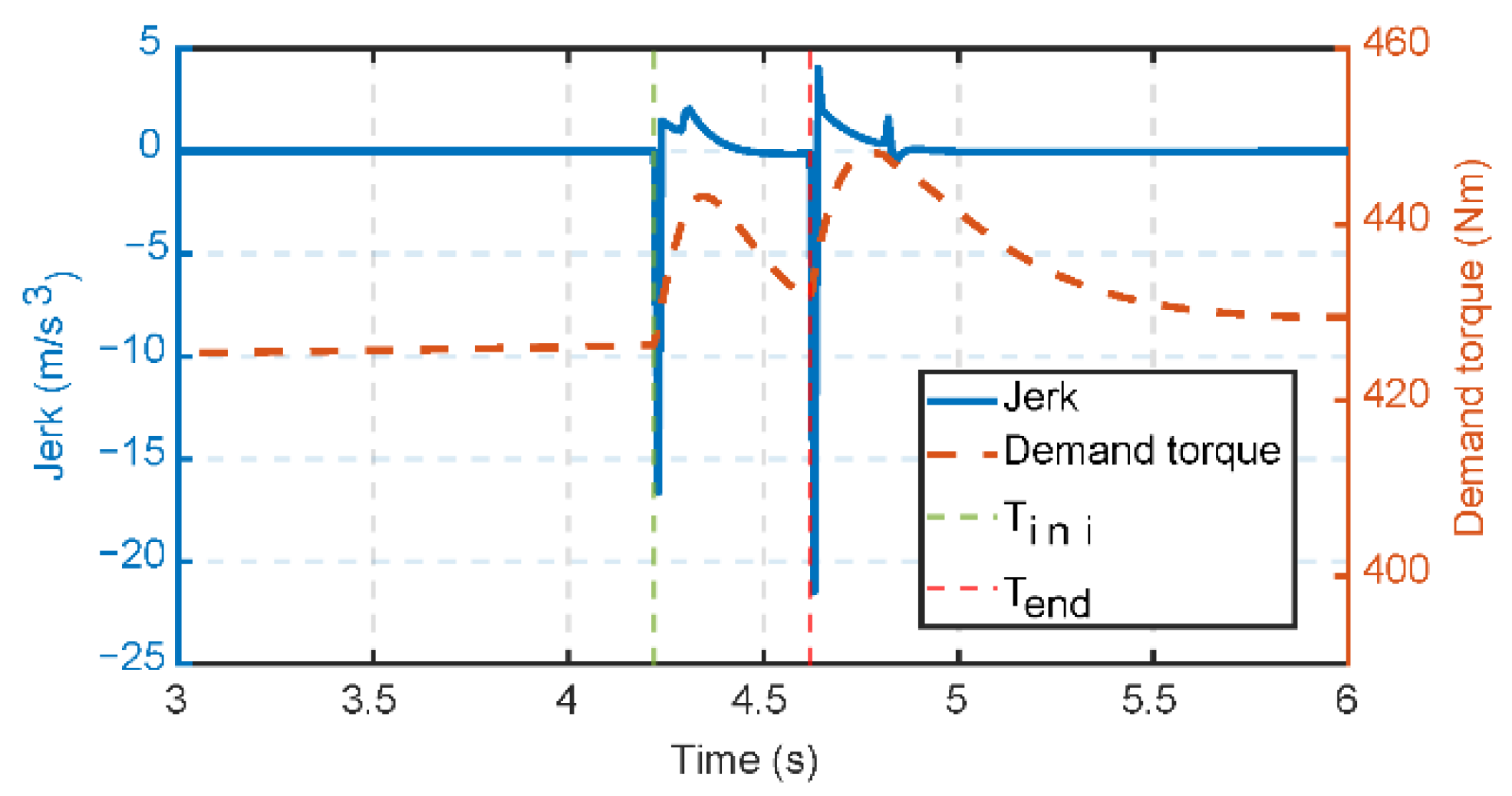
For clutch-less PS-HEVs, mode transitions do not require the consideration of clutch engagement or disengagement. Instead, two primary objectives must be achieved: ensuring continuous power delivery to the output shaft during the transition and bringing the engine to its idle speed. However, the inherent torque response delay of the engine may result in insufficient output shaft torque to meet the overall demand, leading to a short-term power interruption during the transition. Consequently, in the absence of external disturbances and coordinated control, the transition-induced shock predominantly occurs at the onset of the transition and at the initial stage of entering the hybrid mode, as illustrated in Figure 5. The expression for jerk is given by Equation (6), with shock degree being an important indicator of mode transition smoothness. According to German standards, the maximum absolute value of the jerk should not exceed 10 m/s3.
j a b s _ max = j max = d a d t max
where jabs_max represents the maximum absolute value of the jerk, and j denotes the actual value.
In Figure 5, Tini and Tend represent the initial and final moments of the mode transition, respectively. At the initial moment of the mode transition, the inability to coordinate the engine start-up torque demand with the output shaft torque demand increases demand torque and results in negative shock. At the initial moment of entering the hybrid mode, due to the lack of compensation for the engine response delay torque, the entire output shaft power is again insufficient, causing an increase in demand torque and resulting in a negative shock. In summary, mode transition jerk is a mismatch between the demand and actual output torque. Therefore, a controller that quickly provides the demand torque can improve the mode transition jerk.

3.2. PS-HEV Mode Transition with Disturbance

When a PS-HEV encounters disturbances during mode transitions, the quality of the transition deteriorates, as shown in Figure 6. Disturbances generally originate from the engine end and the output shaft end. Engine-end disturbances are primarily caused by incomplete combustion or the influence of auxiliary loads such as air conditioning and power steering. Output shaft end disturbances mainly result from sudden load variations induced by changes in road gradient or surface adhesion. Suppose the disturbances are represented in the form of step torques. The step disturbances at the engine end and the output shaft end can be set to 20 N [6], within the time range [4.25, 4.5] s, as shown in Figure 6a. Figure 6b shows the vehicle’s longitudinal jerk under these disturbances. The results indicate that, under the same disturbances, the jerk from the engine end is greater than that from the output shaft end, and mixed disturbances from both ends further worsen the vehicle’s smoothness to a certain extent.
In summary, external disturbances during mode transitions degrade the smoothness of the transition. Therefore, observing and compensating for external disturbances is necessary to improve smoothness.
Therefore, suppressing disturbance is important to improve the quality of mode transition.

4. Design of PS-HEV Coordinated Control Strategy Based on Fixed-Time Theory

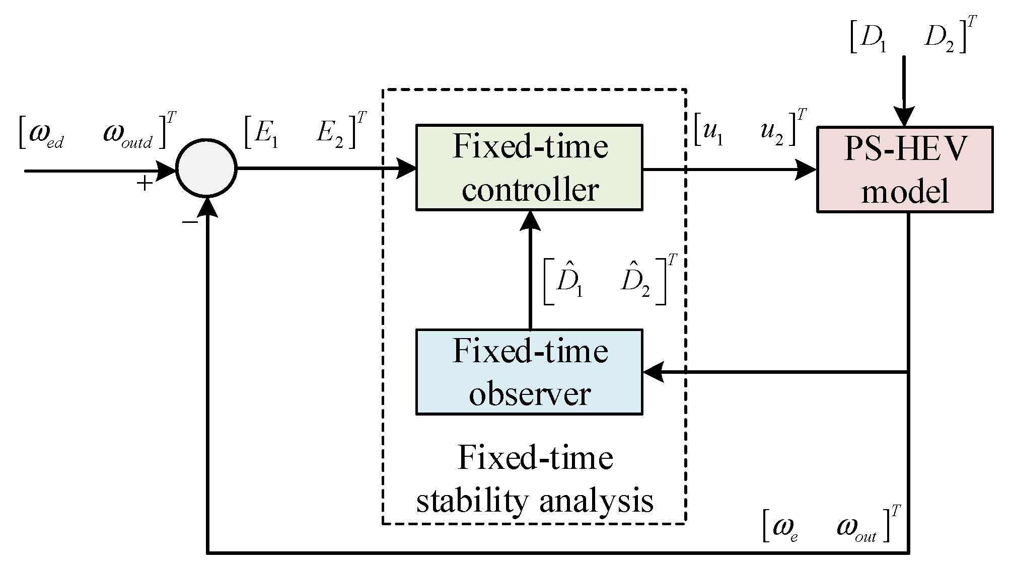
The previous sections identified two main causes of impact during the mode switching process in PS-HEVs: first, a mismatch between the demanded torque and the actual torque; second, disturbances that degrade the quality of mode transition. To address these issues, a novel fixed-time dynamic coordinated control strategy (NFT-DCCS) is proposed to improve mode transition quality. Specifically, a novel fixed-time sliding mode controller is designed using speed tracking error as the input to minimize the difference between the demanded and actual torque and suppress disturbances. On this basis, a fixed-time extended state observer tailored for PS-HEV is designed to achieve precise disturbance estimation, reduce system gain, and enhance mode transition quality, as shown in Figure 7.

4.1. Fixed-Time Terminal Sliding Mode Controller Design

Fixed-time sliding mode control is a control method that combines the fixed-time theory and sliding mode control. Compared with traditional sliding mode control (SMC) and finite-time sliding mode control (FTSMC), its main difference lies in that the convergence time is globally fixed, rather than depending on the size of the initial error. Specifically, the design of the fixed-time terminal sliding mode controller can be divided into the following:
Step 1: Theoretical preparation.
Lemma 1 
([24]). Considering the scalar system
F T S 1 : y ˙ = α s i g κ 1 y β s i g κ 2 y
where κ 1 = m 1 s i g n y 1 , κ 2 = m 2 s i g n 1 y , m1 > 0, 0 < m2 < 1, α > 0, β > 0, and s i g κ 1 y = y κ 1   s i g n ( y ) , then the system (7) is fixed-time stable, and the settling time is given as
T F T max = min α , β , m 1 , m 2 1 β m 1 1 ln 1 + β α , m 2 α 1 m 2 ln 1 + α β + min α , β , m 1 , m 2 1 α 1 m 2 ln 1 + α β , m 1 β m 1 1 ln 1 + β α
The following fixed-time stable system is proposed to improve the convergence rate both far away and close to the equilibrium point.
Theorem 1.
Considering the nonlinear scalar system
F T S   2 : y ˙ = α s i g κ 1 y β s i g κ 2 y R ( y )
where κ 1 = m 1 s i g n y 1 , κ 2 = m 2 s i g n 1 y , m1 > 1, 0 < m2 < 1, α > 0, β > 0, and s i g κ 1 y = y κ 1 s i g n ( y ) , R ( y ) = r + ( 1 r ) tanh 2 ( y ) , tanh ( y ) = e y e y e y + e y , r < R ( y ) < 1 , then the system (7) is fixed-time stable, and the settling time is given as
T F T max = min α , β , m 1 , m 2 1 β m 1 1 ln 1 + β α , m 2 α 1 m 2 ln 1 + α β + min α , β , m 1 , m 2 1 α 1 m 2 ln 1 + α β , m 1 β m 1 1 ln 1 + β α
Proof .
The system (7) can be rewritten as
y ˙ = α s i g m 1 y β s i g 1 m 2 y R ( y ) , y 1 y ˙ = α s i g 1 m 1 y β s i g m 2 y R ( y ) , y < 1
when y 1 , introducing a variable as z 1 = y 1 m 1 , and z ˙ 1 = ( 1 m 1 ) y ˙ y m 1   s i g n ( y ) . Then the system (11) can be modified as
1 1 m 1 z ˙ 1 = α β z 1 1 m 1 m 2 m 2 m 1 m 2 R ( y )
Letting σ = 1 m 1 m 2 m 2 m 1 m 2 , and σ < 1 , we have
1 1 m 1 z ˙ 1 = α β z 1 σ R ( y )
Equation (13) represents a first-order nonlinear differential equation. Subsequently, the equation is rewritten into the following standard form.
d z 1 d t = m 1 1 R ( y ) α + β z 1 σ
Subsequently, the above equation can be expressed as follows.
d t = 1 m 1 1 R ( y ) α + β z 1 σ d z 1
Because lim y + z 1 = 0 , z1 ∈ (0, 1], σ < 1 , and r < R ( y ) < 1 , then the upper bound of the convergence time of Equation (15) can be obtained as
1 m 1 1 0 1 R ( y ) α + β z 1 σ d z 1 < 1 m 1 1 0 1 R ( y ) α + β z 1 d z 1 < 1 m 1 1 0 1 1 α + β z 1 d z 1 < 1 β m 1 1 ln 1 + β α
Assuming that z 1 = y 1 1 m 2 , the upper bound of Equation (11) can be expressed as m 2 α 1 m 2 ln 1 + α β . When y 1 , the conservative convergence time of Equation (11) can be expressed as
T 1 = min α , β , m 1 , m 2 1 β m 1 1 ln 1 + β α , m 2 α 1 m 2 ln 1 + α β
Similarly, we can obtain the conservative convergence time when y < 1 .
T 2 = min α , β , m 1 , m 2 1 α 1 m 2 ln 1 + α β , m 1 β m 1 1 ln 1 + β α
Therefore, the conservative convergence time of Equation (7) can be expressed as
T F T max = T 1 + T 2 = min α , β , m 1 , m 2 1 β m 1 1 ln 1 + β α , m 2 α 1 m 2 ln 1 + α β + min α , β , m 1 , m 2 1 α 1 m 2 ln 1 + α β , m 1 β m 1 1 ln 1 + β α
Remark 1.
If m1m2 = 0 is satisfied, then TFTmax can be expressed as  T F T max = m 1 m 2 α + β m 1 1 1 m 2 .
Remark 2.
Due to the presence of R(y), the proposed fixed-time stabilized system converges faster than the existing method [24]. To verify the shorter convergence time of the proposed system in the paper, it is compared with the method [24] by taking m1 = 3, m2 = 0.3, α = β = 1, and r = 0.5. As shown in Figure 8, the convergence time of the proposed method in this paper is 0.3088 s, and the convergence time of the method [24] is 0.4658 s. Moreover, the timed stabilized system proposed in this paper converges faster than the system given by the method [24] both near and far from the equilibrium point.
Under external disturbances, Equation (4) can be further expressed as
ω ˙ e = U 1 + D 1 ω ˙ o u t = U 2 + D 2
where k e 1 = G 4 G 1 G 4 G 2 G 3 , k e 2 = G 2 G 1 G 4 G 2 G 3 ,
k o u t 1 = G 1 G 1 G 4 G 2 G 3 ,   k o u t 2 = G 3 G 1 G 4 G 2 G 3 ,   U 1 = k e 1 u 1 + k e 2 u 2 ,   U 2 = k o u t 1 u 1 + k o u t 2 u 2 .
Step 2: Design of a new fixed-time sliding mode controller.
The paper proposes new fixed-time sliding mode surfaces and convergence laws, as shown below
S i = E i + 1 R i ( E i ) α i s i g κ 1 i E i + 1 R i ( E i ) β i s i g κ 2 i E i S ˙ i = C 1 i s i g ε 1 i S i + C 2 i s i g ε 1 i S i R i ( S i )
where Si represents the sliding surface, and Si = [S1 S2]T. Ei represents the speed difference and Ei = [E1 E2]T = [ωed − ωe ωoutd − ωout]T. κ 1 i = m 1 i   s i g n E i 1 , κ 2 i = m 2 i   s i g n 1 E i , m1i > 1, 0 < m2i < 1, αi > 0, βi > 0, and s i g κ 1 i E i = E i κ 1 i s i g n ( E i ) , R i ( E i ) = r i + ( 1 r i ) tanh 2 ( E i ) , r i < R ( E i ) < 1 . ε 1 i = m 3 i   s i g n S i 1 , ε 2 i = m 4 i   s i g n 1 S i , m3i > 1, 0 < m4i < 1, C1i > 0, C2i > 0, and s i g ε 1 i S i = S i ε 1 i s i g n ( S i ) , R i ( S i ) = r i + ( 1 r i ) tanh 2 ( S i ) , r i < R ( S i ) < 1 , i = 1, 2.
Linked to Equations (20) and (21), the fixed-time sliding mode control law for the PS-HEV mode transition process can be designed as
U i = ω ˙ i d + α i s i g κ 1 i E i R i ( E i ) + β i s i g κ 2 i E i R i ( E i ) + C 1 i s i g ε 1 i S i + C 2 i s i g ε 1 i S i R i ( S i ) + h i s i g n ( S i )
where ωid = [ωed ωoutd]T, hi = [h1 h2]T, h1 > |D1|, h2 > |D2|.
Step 3: Proof of Stability.
Theorem 2.
For system (20), if the control input is Equation (21) and there exist  κ 1 i = m 1 i   s i g n E i 1 , κ 2 i = m 2 i   s i g n 1 E i , m1i > 1, 0 < m2i < 1, αi > 0, βi > 0, with s i g κ 1 i E i = E i κ 1 i s i g n ( E i ) , R i ( E i ) = r i + ( 1 r i ) tanh 2 ( E i ) , r i < R ( E i ) < 1 , ε 1 i = m 3 i   s i g n S i 1 , ε 2 i = m 4 i   s i g n 1 S i , m3i> 1, 0 < m4i < 1, C1i > 0, C2i > 0, and s i g ε 1 i S i = S i ε 1 i s i g n ( S i ) , R i ( S i ) = r i + ( 1 r i ) tanh 2 ( S i ) , r i < R ( S i ) < 1 , i = 1, 2, then the system (19) is fixed-time stable. The convergence time can be expressed as
T max = T max s i = 0 + T max E i = 0 = min C 1 i , C 2 i , m 3 i , m 4 i 1 C 2 i m 3 i 1 ln 1 + C 2 i C 1 i , 2 m 4 i C 1 i 1 m 4 i ln 1 + C 1 i C 2 i + min C 1 i , C 2 i , m 3 i , m 4 i 1 + m 4 i C 1 i 1 m 4 i ln 1 + C 1 i C 2 i , 1 + m 3 i C 2 i m 3 i 1 ln 1 + C 2 i C 1 i + min α i , β i , m 1 i , m 2 i 1 β i m 1 i 1 ln 1 + β i α i , m 2 i α i 1 m 2 i ln 1 + α i β i + min α i , β i , m 1 i , m 2 i 1 α i 1 m 2 i ln 1 + α i β i , m 1 i β i m 1 i 1 ln 1 + β i α i
Proof. 
Consider the following function:
V = 1 2 S i 2
A derivation of the above formula can be obtained as
V ˙ = S i S ˙ i = S i E ˙ i + α i s i g κ 1 i E i R i ( E i ) + β i s i g κ 2 i E i R i ( E i )
By introducing Equation (23) into Equation (25),
V ˙ = S i S ˙ i = S i C 1 i s i g ε 1 i S i + C 2 i s i g ε 1 i S i R i ( S i ) + h i s i g n ( S i )
When |Si| ≥ 1, Equation (26) can be expressed as
V ˙ = S i C 1 i s i g m 3 i S i + C 2 i s i g 1 / m 4 i S i R i ( S i ) + h i s i g n ( S i ) = C 1 i R i ( S i ) 2 V m 3 + 1 2 C 2 i R i ( S i ) 2 V 1 / m 4 + 1 2 h i S i C 1 i R i ( S i ) 2 V m 3 + 1 2 C 2 i R i ( S i ) 2 V 1 / m 4 + 1 2
According to Theorem 1, the time for the system to reach the sliding mode surface Si = 0 can be expressed as
T s i = 0 _ max 1 = min C 1 i , C 2 i , m 3 i , m 4 i 1 C 2 i m 3 i 1 ln 1 + C 2 i C 1 i , 2 m 4 i C 1 i 1 m 4 i ln 1 + C 1 i C 2 i
Similarly, when |Si| < 1, the time for the system to reach the sliding mode surface Si = 0 can be expressed as
T s i = 0 _ max 2 = min C 1 i , C 2 i , m 3 i , m 4 i 1 + m 4 i C 1 i 1 m 4 i ln 1 + C 1 i C 2 i , 1 + m 3 i C 2 i m 3 i 1 ln 1 + C 2 i C 1 i
Therefore, the time for the system to reach the sliding mode surface Si = 0 can be expressed as
T max s i = 0 = T s i = 0 _ max 1 + T s i = 0 _ max 2 = min C 1 i , C 2 i , m 3 i , m 4 i 1 C 2 i m 3 i 1 ln 1 + C 2 i C 1 i , 2 m 4 i C 1 i 1 m 4 i ln 1 + C 1 i C 2 i + min C 1 i , C 2 i , m 3 i , m 4 i 1 + m 4 i C 1 i 1 m 4 i ln 1 + C 1 i C 2 i , 1 + m 3 i C 2 i m 3 i 1 ln 1 + C 2 i C 1 i
When the system reaches the sliding surface, that is, Si = 0, according to Theorem 1, the time when the system state Ei converges to the origin can be further calculated.
T max E i = 0 = min α i , β i , m 1 i , m 2 i 1 β i m 1 i 1 ln 1 + β i α i , m 2 i α i 1 m 2 i ln 1 + α i β i + min α i , β i , m 1 i , m 2 i 1 α i 1 m 2 i ln 1 + α i β i , m 1 i β i m 1 i 1 ln 1 + β i α i
to the origin in a fixed time. The convergence time can be expressed as
T max = T max s i = 0 + T max E i = 0 = min C 1 i , C 2 i , m 3 i , m 4 i 1 C 2 i m 3 i 1 ln 1 + C 2 i C 1 i , 2 m 4 i C 1 i 1 m 4 i ln 1 + C 1 i C 2 i + min C 1 i , C 2 i , m 3 i , m 4 i 1 + m 4 i C 1 i 1 m 4 i ln 1 + C 1 i C 2 i , 1 + m 3 i C 2 i m 3 i 1 ln 1 + C 2 i C 1 i + min α i , β i , m 1 i , m 2 i 1 β i m 1 i 1 ln 1 + β i α i , m 2 i α i 1 m 2 i ln 1 + α i β i + min α i , β i , m 1 i , m 2 i 1 α i 1 m 2 i ln 1 + α i β i , m 1 i β i m 1 i 1 ln 1 + β i α i
Since hi is an upper bound on the absolute value of the disturbance and the disturbance is difficult to measure through the sensor, it is necessary to design the disturbance observer.
Therefore, the new fixed-time dynamic coordinated control law in the PS-HEV mode transition stage can be expressed as
u 1 u 2 = k e 1 k e 2 k o u t 1 k o u t 2 1 U 1 U 2

4.2. Fixed-Time Extended State Observer Design

By designing an observer to observe the interference, hi is replaced. The disturbance observation is realized and the conservatism of the control law is further reduced. According to ref. [25], the fixed-time extended state observer for system Equation (20) can be expressed as
ω ^ ˙ e = k e 1 u 1 + k e 2 u 2 + D ^ ˙ 1 + μ 1 s i g a 1 δ ( t ) + γ 1 s i g b 1 δ ( t ) D ^ ˙ 1 = μ 2 s i g a 2 δ ( t ) + γ 2 s i g b 2 δ ( t ) + η 1 tanh δ ( t )
ω ^ ˙ o u t = k o u t 1 u 1 + k o u t 2 u 2 + D ^ ˙ 2 + μ 3 s i g c 1 δ ( t ) + γ 3 s i g d 1 δ ( t ) D ^ ˙ 2 = μ 4 s i g c 2 δ ( t ) + γ 4 s i g d 2 δ ( t ) + η 2 tanh δ ( t )
where a i ( 0 , 1 ) , b i ( 1 , + ) , c i ( 0 , 1 ) , d i ( 1 , + ) , and i = 1, 2 satisfy the recurrent relations a i = i a ¯ ( i 1 ) , b i = i b ¯ ( i 1 ) , c i = i c ¯ ( i 1 ) , d i = i d ¯ ( i 1 ) , a ¯ = 1 l 1 , b ¯ = 1 + l 2 , c ¯ = 1 l 3 , d ¯ = 1 + l 4 , with constants that are small enough: l1 > 0, l2 > 0 l3 > 0, l4 > 0. η 1 > D ˙ 1 , η 2 > D ˙ 2 . Observer gains ϕ 1 , ϕ 2 , ϕ 3 , and ϕ 4 are assigned to ensure the following matrices are Hurwitz.
ϕ 1 = μ 1 1 μ 2 0 , ϕ 2 = γ 1 1 γ 2 0 , ϕ 3 = μ 1 1 μ 2 0 , ϕ 4 = γ 3 1 γ 4 0 .
The following error differential equation is established by combining Equations (34) and (35):
e ˙ 1 e = e ˙ 2 e μ 1 s i g a 1 δ ( t ) γ 1 s i g b 1 δ ( t ) e ˙ 2 e = D ˙ 1 μ 2 s i g a 2 δ ( t ) γ 2 s i g b 2 δ ( t ) η 1 tanh δ ( t )
e ˙ 1 o u t = e ˙ 2 o u t μ 3 s i g c 1 δ ( t ) γ 3 s i g d 1 δ ( t ) e ˙ 2 o u t = D ˙ 2 μ 4 s i g c 2 δ ( t ) γ 4 s i g d 2 δ ( t ) η 2 tanh δ ( t )
where e ˙ 1 e = ω ˙ e ω ^ ˙ e , e ˙ 2 e = D ˙ 1 D ^ ˙ 1 , e ˙ 1 o u t = ω ˙ o u t ω ^ ˙ o u t , e ˙ 2 o u t = D ˙ 2 D ^ ˙ 2 .
The design of the fixed-time state observer for both the engine side and the output shaft side is similar. Therefore, it is sufficient to prove fixed-time stability for only one side.
Theorem 3.
Consider the system Equation (20) with the engine-side observer Equation (34) and the error estimation system Equation (36). The state of the error estimation system will converge to the origin within a fixed time. The observer’s state Equation (34) will converge to the actual value within a fixed time.
T F T E S O λ l 1 max Ω 1 ψ 1 l 1 + 1 ψ 2 l 2 ζ l 2
where ψ 1 = λ min ( Q 1 ) / λ max ( Ω 1 ) and ψ 2 = λ min ( Q 2 ) / λ max ( Ω 2 ) .The positive constant ζ λ min ( Q 2 ) .Q1, Q2, Ω1, and Ω2 are nonsingular, symmetric and positive definite matrices satisfied by Ω1P1 + P1TΩ1 = −Q1, Ω2P2+ P2TΩ2= −Q2.
Proof. 
According to ref. [26], the convergence of the observation error to the origin within a fixed time can be divided into the following two steps:
First, define the following error system:
e ˙ 1 e = e ˙ 2 e μ 1 s i g a 1 δ ( t ) γ 1 s i g b 1 δ ( t ) e ˙ 2 e = D ˙ 1 μ 3 s i g a 2 δ ( t ) γ 3 s i g b 2 δ ( t )
According to Theorem 2 in ref. [27], the state of the error system will converge to the origin within a finite time. □
Furthermore, according to Theorem 1 in ref. [26], once the state of the error system reaches the origin at the fixed time T1, i.e., e 1 e = 0 , and after the fixed time T1, it holds that e 2 e = e 1 e = 0 . This implies that the following equation always holds:
e ˙ 2 e = D ˙ 1 η 1 tanh δ ( t ) = 0

5. Simulation and HIL Test Results

5.1. Simulation Results

To verify the effectiveness of the NFT-DCCS control strategy proposed in this paper, the PS-HEV mode transition transient model and mode transition controller are built in Simulink. To verify the superiority of the control strategy proposed in this paper, it is compared with the disturbance compensation strategy (DC-DCCS) [17] and the switch model predictive control strategy (SPMC-DCCS) [28]. The specific parameters are shown in Table 2.
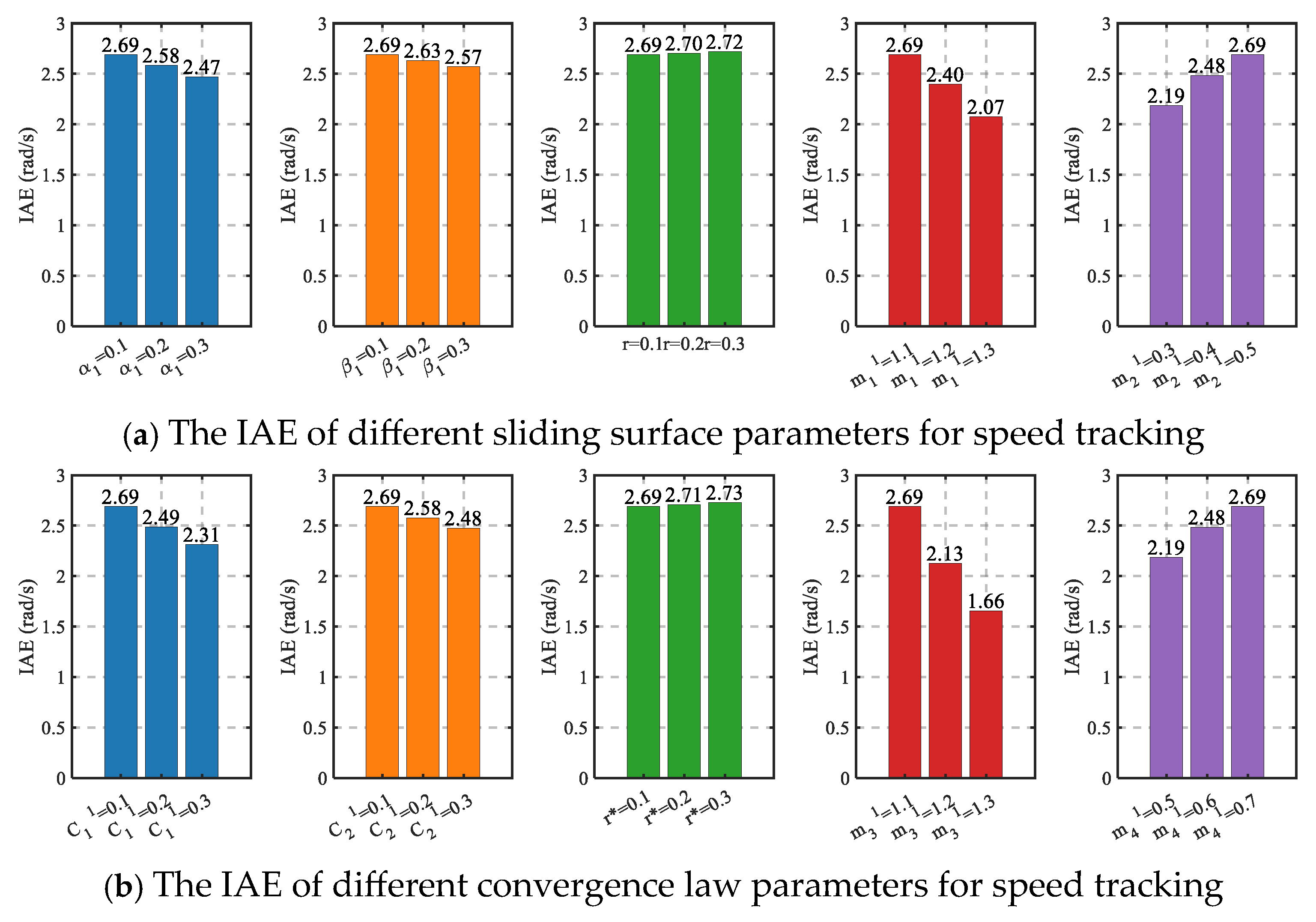
Specifically, to select appropriate controller parameters and ensure satisfactory control performance, the integral of absolute error (IAE) [29] is employed for sensitivity analysis, as illustrated in Figure 9. Figure 9a presents the IAEs of engine speed tracking under varying sliding surface parameters in the fixed-time terminal sliding mode controller. It is worth noting that the output shaft speed tracking exhibits a similar trend to engine speed tracking and is therefore omitted here. Parameters α1 and β1 denote the gain coefficients of the sliding surface. Larger values of α1 and β1 yield smaller IAEs, indicating faster and more accurate tracking. m11 and m21 represent the high- and low-order exponents of the sliding surface, which govern the convergence rates when the absolute tracking error is greater than or less than 1, respectively. Increasing m11 leads to a smaller IAE, reflecting enhanced convergence speed, whereas decreasing m21 can also improve convergence.
As shown in Figure 9b. C11 and C21 are the gain coefficients of the reaching law. Larger values of C11 and C21 similarly result in smaller IAEs and faster, more precise speed tracking. Parameters m31 and m41 are the high- and low-order exponents in the reaching law, governing the convergence rate when the absolute sliding surface value is greater than or less than 1, respectively, with effects analogous to those of m11 and m21. Finally, r and r* are tuning coefficients for the proposed R(E) and R(S). Smaller values of r and r* yield smaller IAEs, thereby enhancing controller performance.
It should be emphasized that controller parameters cannot be arbitrarily large or small; excessively large or small values may cause the desired control input to exceed the actuator limits, ultimately degrading control performance.
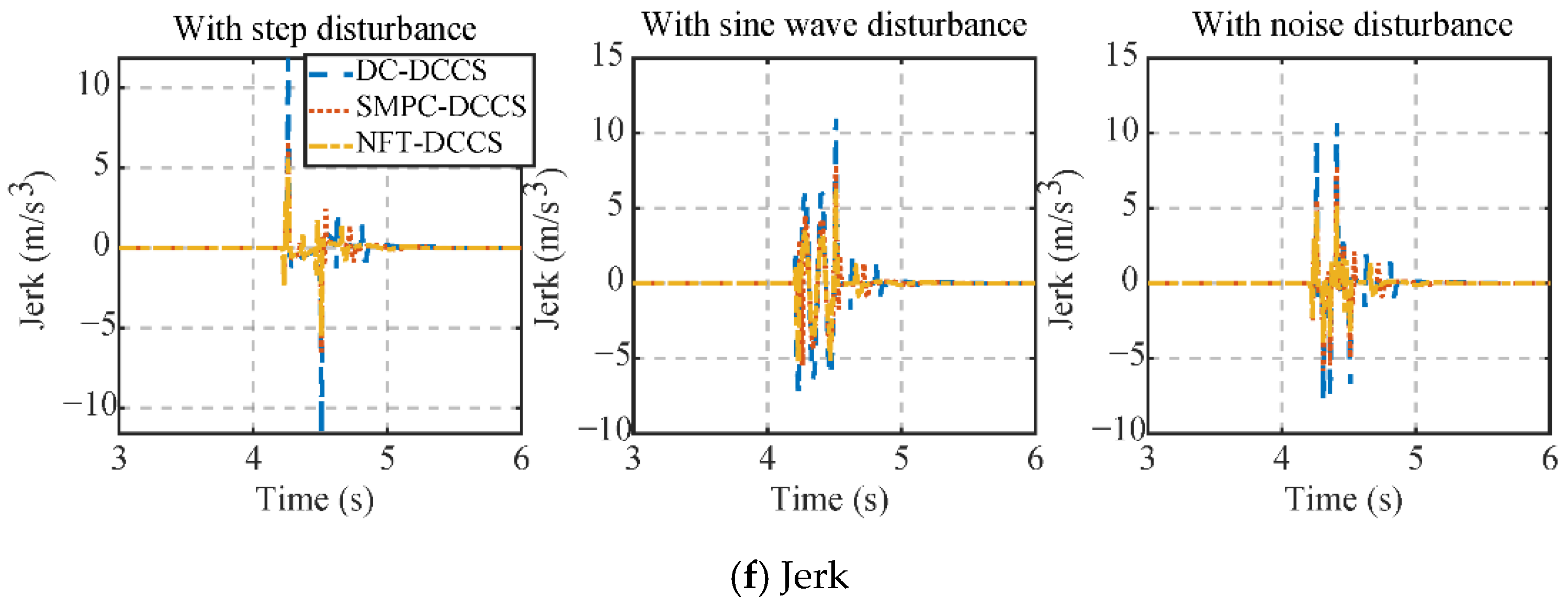
Figure 10 compares the vehicle speed, engine speed, and motor torque responses of NFT-DCCS, SMPC-DCCS, and DC-DCCS under step, sine, and noise disturbances. As shown in Figure 10a, the PS-HEV achieves satisfactory vehicle speed tracking with all three strategies across different disturbance types. Figure 10b presents the engine speed responses. In pure electric mode, the engine remains turned off. During the transition phase, it is brought to idle speed. In hybrid mode, it operates at an economical speed. The results show that NFT-DCCS enables the fastest engine speed tracking, achieving a quicker transition through the MTP phase into hybrid mode, followed by SMPC-DCCS and DC-DCCS. Figure 10c,d display the output torques of MG1 and MG2. In both pure electric and hybrid modes, the motors maintain stable output and adjust torque during the MTP phase to support engine start-up and output shaft speed tracking. Thanks to its rapid convergence both near and far from equilibrium, NFT-DCCS consistently delivers higher torque output, as clearly seen in the figures. Moreover, its performance remains unaffected by disturbance type, demonstrating strong robustness. Figure 10e,f illustrate the mode transition time and jerk during the shift from pure electric to hybrid mode. In Figure 10e, Mode 1 corresponds to the pure electric mode, Mode 4 to the hybrid mode, and Mode 2 to the transition phase. Mode transition time remains constant across disturbance types for all strategies. With NFT-DCCS, the transition takes 0.2 s—16.6% shorter than FT-DCCS (0.24 s) and 50% shorter than DC-DCCS (0.4 s)—primarily due to the superior dynamic performance of the proposed fixed-time sliding mode control law. Figure 10f shows the jerk values under disturbances. NFT-DCCS achieves 5.8 m/s3 under step disturbance and 5.0 m/s3 under the other two cases. SMPC-DCCS peaks at 7.5 m/s3 under noise disturbance, while DC-DCCS reaches 12.4 m/s3 under step disturbance.
In conclusion, these results confirm that NFT-DCCS combines fast convergence with strong disturbance rejection capability.
In addition, Figure 11 has been added to illustrate the estimation performance of the ESO and the proposed FTESO under step disturbances, time-varying sinusoidal disturbances, and white-noise disturbances. Specifically, as shown in Figure 11a, the proposed FTESO exhibits a faster convergence rate and higher estimation accuracy compared to the ESO. Specifically, the estimation error of the ESO converges within 0.09 s, whereas the FTESO achieves convergence in only 0.05 s, representing a 44.4% reduction in convergence time. At the onset and cessation of the disturbance, the ESO shows pronounced estimation errors, while the FTESO maintains significantly smaller errors. Figure 11b demonstrates that under time-varying sinusoidal disturbances, the FTESO continues to outperform the ESO in both accuracy and response speed. The maximum estimation error during switching is only 0.23 Nm for the FTESO, compared with 0.61 Nm for the ESO. As illustrated in Figure 11c, under white-noise disturbances, the FTESO likewise achieves smaller estimation errors and faster convergence than the ESO.
Overall, the proposed FTESO consistently delivers superior estimation performance across various disturbance scenarios. It should be noted, however, that the observer relies on the mathematical model of the system for state reconstruction; thus, parameter mismatches may cause persistent deviations in the estimated states. Furthermore, appropriate filtering of the state variables is required to mitigate the amplification of noise caused by high observer gains. For extreme or special operating conditions, the PS-HEV has more stringent requirements for mode switching time, necessitating a switch within a very short period. Fixed-time control cannot adjust to these real-time demands. In future work, we will consider the adaptability of mode switching conditions and design an adaptive PS-HEV mode switching strategy applicable to all operating conditions.
Furthermore, to evaluate the applicability of the proposed control strategy under various driving conditions, the NEDC cycle was selected as the reference speed for comprehensive validation, as illustrated in Figure 12. The figure not only depicts the tracking performance of the entire vehicle under NEDC driving conditions but also presents the jerk values at the five switching instants. Throughout the entire NEDC driving cycle, only five transitions from pure electric mode to hybrid mode are required. Moreover, the results indicate that in all five transitions, the maximum jerk remains below 4 m/s3, which convincingly demonstrates the feasibility and superior performance of the proposed control strategy.

5.2. HIL Test Results

Furthermore, to verify the real-time performance of the control strategy presented in this paper, an HIL test platform as shown in Figure 13 was set up. The HCU-HIL testing system comprises two main components: a test cabinet housing the main power switch, a D2P controller, and an NI real-time simulator, and a host computer running NI Veristand testing software and the MotoHawk development platform. The testing procedure begins by dividing the Simulink model into a vehicle model and a controller model, followed by discretization of both. The I/O ports of the vehicle model are then replaced with NI Veristand interfaces and compiled into a DLL. The controller model is compiled in the MotoHawk platform and downloaded to the D2P controller. The vehicle model DLL is subsequently loaded into NI Veristand, with network settings adjusted to place the real-time target and host computer on the same subnet. Finally, the model and controller I/O ports are mapped using a CAN DBC file, enabling closed-loop signal transmission via Ethernet.
From the HIL test results shown in Figure 14, the three control strategies exhibit similar behaviors under different disturbance conditions as in the simulations, thereby validating the feasibility of the proposed control approach. Compared with the simulation results, the jerk values in the HIL tests are slightly higher, primarily because the HIL experiments employ an in-vehicle grade controller, whose operating environment and configuration differ from those in simulations. Nevertheless, under all three disturbance scenarios, the proposed NFT-DCCS not only ensures smooth mode transitions of the PS-HEV but also maintains superior control performance. Specifically, the jerk values and mode transition times are both lower than those of the other two controllers. Overall, the designed NFT-DCCS satisfies the computational constraints of the in-vehicle grade controller while delivering outstanding control performance.

6. Conclusions

To address the mode switching challenge in PS-HEVs, this study proposes a fixed-time dynamic coordination control strategy and demonstrates its fixed-time stability. Specifically, a control law with strong disturbance suppression capability is developed based on a novel fixed-time sliding mode surface and reaching law, enabling faster convergence and improved robustness. Furthermore, a fixed-time extended state observer is integrated for real-time disturbance estimation, thereby reducing the conservatism of the control law. Simulation results confirm that the proposed strategy can effectively suppress disturbances and significantly enhance mode switching performance. Future work will focus on extending the proposed approach to address more complex operating conditions, developing higher-performance mode transition control strategies, and validating the proposed method through bench testing platforms or real vehicle experiments.

Author Contributions

Conceptualization, H.Z. and Y.Z.; Software, H.Z.; Validation, H.Z., H.Y., F.Z.; Investigation, H.Z. and H.Y.; Data curation, H.Z., H.Y., F.Z. and X.L.; Writing—original draft, H.Z.; Writing—review and editing, H.Z., H.Y. and Y.Z.; Supervision, Y.Z.; Project administration, Y.Z. All authors have read and agreed to the published version of the manuscript.

Funding

This research was sponsored by QingLan Project of Jiangsu Higher Education Institutions (JSQL2023, JSQL2024), the National Natural Science Foundation of China (51575238), Major scientific research projects of Changzhou Vocational Institute of Mechatronic Technology (2023-ZDKYXM-11).

Data Availability Statement

The original contributions presented in this study are included in the article. Further inquiries can be directed to the corresponding author.

Conflicts of Interest

The authors declare that they have no known competing financial interests or personal relationships that could have appeared to influence the work reported in this paper.

References

  1. An, S.; Qiu, J.; Lin, J.; Yao, Z.; Liang, Q.; Lu, X. Planning of a multi-agent mobile robot-based adaptive charging network for enhancing power system resilience under extreme conditions. Appl. Energy 2025, 395, 126252. [Google Scholar] [CrossRef]
  2. Rong, X.; Shi, D.; Wang, S.; Yin, C.; Li, C. Control allocation-based adaptive dynamic coordinated control of compound power-split hybrid electric vehicles. Proc. Inst. Mech. Eng. Part C J. Mech. Eng. Sci. 2024. [Google Scholar] [CrossRef]
  3. Sabri, M.F.M.; Danapalasingam, K.A.; Rahmat, M.F. A review on hybrid electric vehicles architecture and energy management strategies. Renew. Sustain. Energy Rev. 2016, 53, 1433–1442. [Google Scholar] [CrossRef]
  4. Zhang, F.; Wang, L.; Coskun, S.; Pang, H.; Cui, Y.; Xi, J. Energy management strategies for hybrid electric vehicles: Review, classification, comparison, and outlook. Energies 2020, 13, 3352. [Google Scholar] [CrossRef]
  5. Chen, B.; Pan, X.; Evangelou, S.A. Optimal energy management of series hybrid electric vehicles with engine start–stop system. IEEE Trans. Control Syst. Technol. 2022, 31, 660–675. [Google Scholar] [CrossRef]
  6. Zhao, Q.; Rong, X.; Shi, D. Research on switching control based sliding mode coordination strategy of hybrid electric vehicle. Proc. Inst. Mech. Eng. Part I J. Syst. Control Eng. 2024, 238, 1872–1887. [Google Scholar] [CrossRef]
  7. Rong, X.; Shi, D.; Wang, S. Adaptive anti-saturation fixed-time control for PS-HEV mode transition with predefined performance. IEEE Trans. Power Electron. 2025, 40, 13852–13865. [Google Scholar] [CrossRef]
  8. Huang, Y.; Wang, H.; Khajepour, A.; Li, B.; Ji, J.; Zhao, K.; Hu, C. A review of power management strategies and component sizing methods for hybrid vehicles. Renew. Sustain. Energy Rev. 2018, 96, 132–144. [Google Scholar] [CrossRef]
  9. Zhu, F.; Chen, L.; Yin, C.; Shu, J. Dynamic modelling and systematic control during the mode transition for a multi-mode hybrid electric vehicle. Proc. Inst. Mech. Eng. Part D J. Automob. Eng. 2013, 227, 1007–1023. [Google Scholar] [CrossRef]
  10. Sahu, R.K.; Srivastava, D.K. Model-Based Calibration of a Gasoline-Fueled Spark Ignition Engine for Torque Control Application Using Mean Value Engine Modeling. SAE Int. J. Engines 2023, 16, 855–870. [Google Scholar] [CrossRef]
  11. Zheng, T.; Zhang, Y.; Li, Y.; Shi, L. Real-time combustion torque estimation and dynamic misfire fault diagnosis in gasoline engine. Mech. Syst. Signal Process. 2019, 126, 521–535. [Google Scholar] [CrossRef]
  12. Feng, S.; Li, X.; Zhang, S.; Jian, Z.; Duan, H.; Wang, Z. A review: State estimation based on hybrid models of Kalman filter and neural network. Syst. Sci. Control Eng. 2023, 11, 2173682. [Google Scholar] [CrossRef]
  13. Gao, A.; Fu, Z.; Tao, F. Dynamic coordinated control based on sliding mode controller during mode transition with ICE starting for an HEV. IEEE Access 2020, 8, 60428–60443. [Google Scholar] [CrossRef]
  14. Chen, L.; Xi, G.; Sun, J. Torque coordination control during mode transition for a series–parallel hybrid electric vehicle. IEEE Trans. Veh. Technol. 2012, 61, 2936–2949. [Google Scholar] [CrossRef]
  15. Yin, C.; Xie, Y.; Shi, D.; Wang, S.; Zhang, K.; Li, M. Sliding mode coordinated control of hybrid electric vehicle via finite-time control technique. ISA Trans. 2024, 146, 541–554. [Google Scholar] [CrossRef]
  16. Ding, J.; Jiao, X. Mode transition prescribed performance control of connected hybrid electric vehicles based on driver intention fuzzy prediction. Control Eng. Pract. 2024, 142, 105748. [Google Scholar] [CrossRef]
  17. Chen, L.; Wang, J.; Cai, Y.; Shi, D.; Wang, R. Mode transition control of a power-split hybrid electric vehicle based on improved extended state observer. IEEE Access 2020, 8, 207260–207274. [Google Scholar] [CrossRef]
  18. Wang, W.; Zhang, Y.; Sun, X.; Xiang, C.; Yang, C. Model-based double closed-loop coordinated control strategy for the electro-mechanical transmission system of heavy power-split HEVs. Automot. Innov. 2021, 4, 44–55. [Google Scholar] [CrossRef]
  19. Wang, J.; Cai, Y.; Chen, L.; Shi, D.; Wang, S.; Zhu, Z. Research on compound coordinated control for a power-split hybrid electric vehicle based on compensation of non-ideal communication network. IEEE Trans. Veh. Technol. 2020, 69, 14818–14833. [Google Scholar] [CrossRef]
  20. Xue, H.; Wang, X. Prescribed Performance Ship Tracking Control with a Novel Predefined-Time Performance Function. IET Intell. Transp. Syst. 2025, 19, e70014. [Google Scholar] [CrossRef]
  21. Cheng, W.; Zhang, K.; Jiang, B.; Ding, S.X. Fixed-time fault-tolerant formation control for heterogeneous multi-agent systems with parameter uncertainties and disturbances. IEEE Trans. Circuits Syst. I Regul. Pap. 2021, 68, 2121–2133. [Google Scholar] [CrossRef]
  22. Cui, G.; Yang, W.; Yu, J.; Li, Z.; Tao, C. Fixed-time prescribed performance adaptive trajectory tracking control for a QUAV. IEEE Trans. Circuits Syst. II Express Briefs 2021, 69, 494–498. [Google Scholar] [CrossRef]
  23. Chen, X.; Gong, P. Transient and steady-state performance improvement of IM drives based on dual-torque model. Machines 2023, 11, 490. [Google Scholar] [CrossRef]
  24. Yu, L.; He, G.; Wang, X.; Zhao, S. Robust fixed-time sliding mode attitude control of tilt trirotor UAV in helicopter mode. IEEE Trans. Ind. Electron. 2021, 69, 10322–10332. [Google Scholar] [CrossRef]
  25. Zhang, J.; Yu, S.; Yan, Y. Fixed-time extended state observer-based trajectory tracking and point stabilization control for marine surface vessels with uncertainties and disturbances. Ocean Eng. 2019, 186, 106109. [Google Scholar] [CrossRef]
  26. Zhang, L.; Wei, C.; Wu, R.; Cui, N. Fixed-time extended state observer based non-singular fast terminal sliding mode control for a VTVL reusable launch vehicle. Aerosp. Sci. Technol. 2018, 82–83, 70–79. [Google Scholar] [CrossRef]
  27. Basin, M.; Yu, P.; Shtessel, Y. Finite-and fixed-time differentiators utilising HOSM techniques. IET Control Theory Appl. 2017, 11, 1144–1152. [Google Scholar] [CrossRef]
  28. Hu, J.; He, H.; Wang, Z.; Ji, S.; Duan, Z. A switched model predictive control with parametric weights-based mode transition strategy for a novel parallel hybrid electric vehicle. Control Eng. Pract. 2025, 155, 106161. [Google Scholar] [CrossRef]
  29. Wang, S.; Rong, X.; Shi, D.; Yin, C. Research on fixed-time robust control allocation of the mode transition for CPS-HEV considering actuator uncertainties. IEEE Trans. Transp. Electrif. 2025. [Google Scholar] [CrossRef]
Figure 1. Power-split HEV power coupling mechanism.
Energies 18 04438 g001
Figure 2. Lever diagram of dual planetary gears.
Energies 18 04438 g002
Figure 3. Power source efficiency.
Energies 18 04438 g003
Figure 4. The mode transition logic.
Energies 18 04438 g004
Figure 5. Mode transition process problem description.
Energies 18 04438 g005
Figure 6. Vehicle jerk under disturbance.
Energies 18 04438 g006
Figure 7. Novel fixed-time dynamic coordinated control strategy.
Energies 18 04438 g007
Figure 8. Fixed-time stabilization system convergence time.
Energies 18 04438 g008
Figure 9. The IAE of different parameters for speed tracking.
Energies 18 04438 g009
Figure 10. Power source speed, torque, and evaluation indicators.
Energies 18 04438 g010aEnergies 18 04438 g010b
Figure 11. Fixed-time extended state observer effect.
Energies 18 04438 g011
Figure 12. Mode transition process under NEDC.
Energies 18 04438 g012
Figure 13. HIL test platform.
Energies 18 04438 g013
Figure 14. Engine speed, mode, and jerk.
Energies 18 04438 g014
Table 1. The parameters of the vehicle model.
ParametersValue
Vehicle mass m1525 kg
Air resistance coefficient CD0.31
Air density ρ1.23 m3/kg
Frontal area A2.02 m2
Rolling resistance coefficient f0.008
The radius of wheel r0.317 m
The ratio of the final drive ifd3.269
Characteristic parameter of PG1 and PG2 K1/K22.6/2.639
Engine maximum power Pe73 kW
MG1 maximum power PMG123 kW
MG2 maximum power PMG260 kW
Table 2. Specific parameters of NFT-DCCS.
ParametersValueParametersValue
α10.1m111.1
α20.1m210.3
β10.1m311.1
β20.1m410.5
C110.1m121.1
C210.07m220.5
C120.1m321.1
C220.1m420.5
r10.5r1*0.5
r20.6r2*0.6
μ1100γ1200
μ270γ2100
μ3100γ3200
μ450γ480
η12η20.5
a ¯ 0.7 b ¯ 1.3
c ¯ 0.9 d ¯ 1.1
Disclaimer/Publisher’s Note: The statements, opinions and data contained in all publications are solely those of the individual author(s) and contributor(s) and not of MDPI and/or the editor(s). MDPI and/or the editor(s) disclaim responsibility for any injury to people or property resulting from any ideas, methods, instructions or products referred to in the content.