Abstract
In the context of achieving low-carbon goals, building low-carbon energy systems is a crucial development direction and implementation pathway. Renewable energy is favored because of its clean characteristics, but the access may have an impact on the power grid. Microgrid technology provides an effective solution to this problem. Uncertainty exists in single microgrids, so multiple microgrids are introduced to improve system stability and robustness. Electric carbon trading and profit redistribution among multiple microgrids have been challenges. To promote energy commensurability among microgrids, expand the types of energy interactions, and improve the utilization rate of renewable energy, this paper proposes a cooperative operation optimization model of multi-microgrids based on the green certificate and carbon trading mechanism to promote local energy consumption and a low carbon economy. First, this paper introduces a carbon capture system (CCS) and power-to-gas (P2G) device in the microgrid and constructs a cogeneration operation model coupled with a power-to-gas carbon capture system. On this basis, a low-carbon operation model for multi-energy microgrids is proposed by combining the local carbon trading market, the stepped carbon trading mechanism, and the green certificate trading mechanism. Secondly, this paper establishes a cooperative game model for multiple microgrid electricity carbon trading based on the Nash negotiation theory after constructing the single microgrid model. Finally, the ADMM method and the asymmetric energy mapping contribution function are used for the solution. The case study uses a typical 24 h period as an example for the calculation. Case study analysis shows that, compared with the independent operation mode of microgrids, the total benefits of the entire system increased by 38,296.1 yuan and carbon emissions were reduced by 30,535 kg through the coordinated operation of electricity–carbon coupling. The arithmetic example verifies that the method proposed in this paper can effectively improve the economic benefits of each microgrid and reduce carbon emissions.
1. Introduction
One of the leading causes of global warming is the sharp rise in carbon emissions. To achieve sustainable development, governments have developed strategies to reduce carbon emissions. Carbon emission reduction has become a key area in power system research [1]. Renewable energy sources such as solar and wind are favored for their cleanliness; for example, the Chinese State Council’s “2024–2025 Energy Conservation and Carbon Reduction Action Plan” mandates that non-fossil energy consumption accounts for 20% of total energy consumption by 2025, accompanied by quantitative targets of adding 200 gigawatts of new wind and solar power capacity and achieving renewable energy consumption exceeding 1.1 billion tons of standard coal, but their access may impact the power grid [2,3]. Microgrid technology has emerged as a solution to this problem. The emergence of microgrid technology provides an effective solution to this problem. It integrates multiple distributed power sources, energy storage, and loads to enhance the reliability of the power supply. Microgrids can operate independently from main grid faults, provide a stable power supply, and enhance the stability and robustness of the power system. At the same time, it promotes diversified energy utilization. Microgrids can integrate different energy resources, such as solar energy, wind energy, energy storage, etc., to promote diversified energy utilization. Microgrids can promote the access and utilization of renewable energy, reduce the dependence on traditional fossil energy, promote the development of clean energy, and help to meet the challenges of climate change [4]. Microgrids’ role is becoming increasingly prominent in the energy transition and the construction of new power systems [5]. In June 2025, new regulations issued by the National Energy Administration of China will exempt smart microgrids, distributed photovoltaic power generation, and new energy storage technologies from power business licensing requirements, significantly reducing the institutional costs of the “behind-the-meter” power sales model and mandating that grid companies provide non-discriminatory interconnection services. However, individual microgrids are affected by uncertainties such as new energy output and price fluctuations in the power market, and they suffer from low energy utilization and high operating costs. At the same time, the microgrid scale is relatively small, and once a failure or problem occurs, it may affect the operation of the entire microgrid system, and there is system vulnerability. For this reason, forming a multi-microgrid system (MMG) has become an effective strategy to enhance the new energy acceptance capacity, improve the reliability and stability of the power supply, and reduce operating costs [6]. In summary, MMGs are essential in enhancing the utilization of new energy and carbon emission reductions through energy sharing and optimal scheduling [7,8,9].
Given that each microgrid is divided into different interests [8], it is crucial to construct a reasonable trading model to coordinate the interests among microgrids. In literature [10], a multi-microgrid system based on the P2P transaction model is proposed to address the challenges of single microgrid operation, which is a decentralized transaction model that allows both parties to complete the transaction without the intervention of the Distribution System Operator (DSO), thus giving the transaction more flexibility [11,12]. Regarding the P2P energy trading model between distributed multi-microgrid entities, the research direction covers multi-intelligence organizations (MIOs) [13], blockchain [14], and game theory [15,16]. In this paper, we focus on game theoretical approaches, and existing studies have proved that game optimization models perform well in dealing with complex interest problems in the energy trading process. Game methods can be mainly categorized into two types: non-cooperative games and cooperative games. In non-cooperative games, each microgrid trades to maximize its interests. However, in the non-cooperative game environment, there are problems of incomplete information and insufficient carbon emission reduction motivation due to the lack of an effective information-sharing mechanism [17]. Literature [18] further shows that non-cooperative games emphasize individual rationality and a self-interested decision-making process, which leads to the existence and uniqueness of Nash equilibrium not being guaranteed, and the result is usually a local optimum. Therefore, current research prefers to adopt cooperative games to minimize the total cost of multi-microgrid systems and distribute benefits by forming coalitions. As an essential branch of game theory, Nash bargaining theory provides an effective way to realize the cooperative game process. In this theory, each game player can put forward its proposal or strategy and expects to obtain the most favorable result through negotiation, i.e., realizing the Nash equilibrium. Literature [19], based on the Nash negotiation model, provides an in-depth study of wind–hydrogen three-body electric energy transactions and the use of the augmented Lagrange multiplier method to optimize the volume of electric energy sharing transactions, and the three parties share the benefits equally to achieve the maximization of microgrid alliance revenue. Literature [20] proposes a collaborative planning and operation method for a wind–hydrogen–heat multi-intelligent body energy system, based on the Nash bargaining game, which significantly improves the interests of each participant and the alliance as a whole. Literature [21] reduces the operation cost and promotes the use and consumption of renewable energy through the establishment of a multi-microgrid cooperative alliance by utilizing a cooperative game. In summary, in P2P electricity trading, microgrids utilize a Nash bargaining theory cooperative game, to reduce cost and solve efficiently via ADMM, which demonstrates the broad application prospect of Nash bargaining theory in microgrid energy trading.
In addition to P2P electricity trading, some literature explores the introduction of carbon trading to enhance the economic benefits of microgrids. Literature [18] adopts a stepped carbon trading mechanism, where resource-rich subjects support other subjects to effectively reduce carbon emissions and cut costs, maximizing social benefits and significantly reducing carbon emissions. Literature [22] combines carbon trading with electricity trading to reduce carbon emissions from microgrids. However, the literature discusses the distribution of benefits in a general way, and the benefits of each microgrid are increased by a comparable amount without considering the actual degree of contribution, which makes it challenging to ensure that the benefits of each microgrid are effectively guaranteed.
When exploring the benefit distribution mechanism, academics generally focus on two strategies: the Shapley value method and the asymmetric bargaining method. Literature [23] uses the Shapley method to distribute benefits based on a marginal contribution to ensure the fair distribution of benefits emerging from multi-microgrid systems. Literature [24] proposes an improved Shapley value method considering the electric interaction, carbon reduction, and FRC supply factors to share the shared energy storage cost fairly. However, when the microgrid scale is large, the Shapley value method faces the problem of “portfolio explosion,” which reduces the computational efficiency [25]. To cope with this challenge, literature [26] uses a nonlinear energy mapping function to realize contribution-based asymmetric bargaining. Unfortunately, however, the method only considers the contribution of electrical energy and ignores the contribution of microgrids in terms of carbon emission reduction. To compensate for this deficiency, literature [27] combines electric energy and carbon emission reduction contributions and proposes that benefits be allocated based on the combined contribution rate, which is effective.
In summary, most studies have primarily focused on the operational optimization of microgrid systems, particularly the power interaction between microgrids and distribution grids. However, current research mainly focuses on power optimization between multi-microgrid systems, with relatively few studies exploring the optimal allocation of power and carbon quotas within multi-microgrid systems and the distribution of profits. Therefore, this study, based on the intrinsic characteristics of microgrids, delves into how to effectively mobilize renewable resources within each microgrid to enhance the overall utilization rate of multi-microgrid systems.
To improve economic efficiency and enhance the effectiveness of carbon emission reduction, many works of literature have explored the low-carbon retrofit of microgrid cogeneration units by utilizing carbon-capture systems and power-to-gas equipment. Literature [28] proposes a low-carbon retrofit scheme and a multi-microgrid power-sharing strategy based on asymmetric Nash negotiation, and the simulation results show that this strategy has a significant carbon-reduction effect. Literature [29], on the other hand, focuses on the retrofit of carbon-capture power plants by introducing flue gas diversion and controlling the solution concentration method to realize CO2 absorption, storage, time-shift, and release, and moving the power-consuming process to the night time to promote the abandonment of wind consumption. This strategy realizes both economic and low-carbon benefits, widens the lower limit of net output of thermal power units, and improves the spinning reserve capacity.
The Central Office and the State Council require the establishment of a unified national carbon emissions trading market by 2027 and have proposed for the first time a “resource and environmental factor reserve adjustment system” to prevent carbon price fluctuations. Literature [30] uses a quantile autoregressive distributed lag model to quantitatively evaluate the effects of economic policy uncertainty (EPU) and geopolitical risk (GPR) on volatility in carbon futures (carbon trading price [CTP]). The findings provide targeted recommendations for policymakers to stabilize CTP and contribute towards achieving sustainable development. In 2022, China’s National Development and Reform Commission (NDRC) emphasized the release of green power consumption potential in the Implementation Plan for the Promotion of Green Consumption, proposing to promote green power and green certificate trading in an integrated manner and to strengthen their convergence with carbon emissions trading. However, there is a problem of incoherence between China’s carbon trading, green certificate trading, and the electricity market. However, there is an uncoordinated problem between carbon trading, green certificate trading, and the electricity market in China [31]. Existing research mostly stays at the stage of the parallel operation of CET and GCT and has not explored its intrinsic connection in depth. Literature [32] considered GCT and CET in MES but only incorporated them into the system without analyzing their relevance in depth. Literature [33] explores the equivalent interaction of green certificates and carbon trading but does not consider the role of green certificate quotas between GT and HFC in GCT. To deeply understand the combined impact of these mechanisms, it is necessary to jointly apply CET and GCT to MES optimal scheduling to explore their specific impact on the optimal operation of multi-microgrids.
In summary, this paper aims to propose a cooperative game operation optimization method for multi-microgrids considering green certificates and carbon trading to improve energy utilization and reduce carbon emissions. By leveraging market mechanisms to optimize resource allocation, the method further enhances the economic and environmental benefits of multi-microgrid systems, strengthens its stability and reliability, and achieves efficient energy sharing and optimized allocation. The paper constructs a low-carbon operation model of a multi-microgrid containing P2G-CCS, and the coupled electric–carbon trading between multi-microgrids is realized based on the Nash negotiation theory. Through a simulation analysis, it is verified that the operation cost of the system is significantly reduced, which has a positive role in promoting the transition of the energy system to a low-carbon economy.
The main innovations of this paper are summarized as follows:
(1) Further investigation into the synergistic mechanisms of green certificates and carbon trading in multi-microgrid systems. Addressing the limitations of existing research, which has primarily focused on single integrated energy systems while neglecting the role of market mechanisms and multi-microgrid synergy, this paper explores the synergistic effects and interactive relationships between green certificates and carbon trading. It also constructs a multi-microgrid system operational cost model that accounts for the interaction between green certificates and carbon trading.
(2) A coupled operation model for CCS-P2G systems in multi-microgrid systems has been established. To study the synergistic effects of emission-reduction technologies with multi-microgrid systems and further promote the integration of renewable energy into multi-microgrid systems, this paper introduces CCS systems and P2G equipment into the architectural design of multi-microgrid systems and performs detailed modeling, thereby establishing a coupled operation mode for CCS-P2G systems in multi-microgrid systems.
(3) An optimization solution algorithm process for multi-microgrid cooperative operation, considering green certificates and carbon trading, was established. Addressing the limited consideration of carbon quota trading between microgrids in existing research and the fact that most studies on multi-microgrid collaborative optimization focus solely on system-wide optimization while neglecting the issue of profit distribution between microgrids after the interaction, this paper incorporates electricity and carbon quota trading between multi-microgrid systems in the solution process. In solving the optimization objective function for multi-microgrid collaborative operation, it is decomposed into two subproblems: subproblem P, which minimizes the cost of electricity–carbon interaction in the multi-microgrid system, and subproblem Q, which involves the reasonable allocation of profits. The ADMM algorithm is employed to solve the subproblem of minimizing costs after the electricity–carbon interaction, while an asymmetric energy mapping contribution function is used for profit distribution.
2. Model Building
In this paper, a multi-energy microgrid operation framework is constructed (Figure 1). For a single microgrid, an electricity–gas–heat coupling operation framework is designed that includes CHP units, electric energy storage, wind power, photovoltaic, gas boilers, thermal energy storage, etc. CHP units are the primary source of CO2 emissions within the microgrid. P2G equipment and CCS technology have been introduced to reduce carbon emissions, and a local carbon trading market has been established so that market participants can trade carbon allowances. The main body of the microgrid has an independent electro–carbon energy interaction terminal (MET), which realizes P2P trading through wireless network communication, and the trading software is called an electro-thermal carbon energy trading system (ETS). Based on this, a multi-energy microgrid low-carbon operation model is constructed.
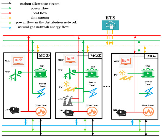
Figure 1.
Multi-microgrid operational framework.
2.1. Models of Various Systems Within Microgrids
2.1.1. CHP Unit Model with Coupled P2G-CCS
The distributed power source of microgrids is mainly gas turbines. The gas turbine can generate electricity by burning natural gas and at the same time releasing CO2, and the relationships among its power generation, heat generation, and the amount of natural gas consumed, as well as the amount of CO2 produced, are respectively as follows:
In the formula, , is the gas turbine power generation, heat generation efficiency; is the low calorific value of natural gas; is microgrid i at time t for gas turbine power generation consumption of natural gas; , is the gas turbine power generation, heat generation power; ,,, is the gas turbine power generation, heating power of the upper and lower limits; and is the gas turbine combustion of natural gas to release the amount of CO2; is the gas turbine carbon emissions conversion factor.
To effectively reduce carbon emissions, this paper adds CCS and P2G devices outside the gas turbine, and the coupled operation of P2G-CCS can realize the recycling of energy in the system, which mainly includes the following steps:
(1) CCS captures CO2
In the formula, is the amount of CO2 captured by the CCS system of microgrid i at time t; is the conversion coefficient between the amount of electric power consumed by the CCS and the amount of CO2 captured by the CCS, which is taken as 0.55 in this paper [34]; and are the amounts of CO2 delivered by the CCS system of microgrid i to the P2G equipment and the carbon storage equipment, respectively, at time t; is the amount of electric power consumed by the CCS system of microgrid i at time t to capture CO2; and and are the amounts of electric power provided to the CCS system by wind power and photovoltaic (PV) at microgrid i at time t.
(2) P2G equipment absorbs and converts CO2
In the formula, is the amount of CO2 needed by the P2G device to generate CH4 of microgrid i at time t; is the conversion coefficient between the amount of CO2 needed by the P2G device to produce CH4 and the electric power consumed by the P2G, which is taken as 0.5 in this paper [35]; is the electric conversion efficiency of CH4 generated by the P2G, which is taken as 0.55 in this paper [33]; is the amount of carbon discharged from carbon storage; is the electric power consumed by the P2G device; is CH4 generated from CO2 by P2G devices by consuming a certain amount of electricity; and and are the electric power provided to P2G devices by wind power and PV power, respectively.
Conventional electric-to-gas conversion is divided into two stages: production of electric hydrogen and methanation. With the continuous development of Carbon Capture Utilization and Storage (CCUS) technology, this study focuses on the source supplementation of carbon capture, especially on improving the carbon capture from low-carbon gas turbines after flue gas shunt. On this basis, a three-stage refinement model of P2G that integrates the mining of wind and light abandonment mining for hydrogen production and flue gas shunt carbon capture of waste carbon is proposed. For more detailed parametric modeling, please refer to the literature [33]. After the P2G-CCS absorption conversion, the actual carbon emissions of the CHP units and the total carbon emissions of individual microgrids can be expressed as follows.
In the formula, is the carbon emission of microgrid i at time t; is the purchased power of microgrid i to the superior grid at time t; and are the carbon emission coefficients; and is the natural gas consumption in the gas boiler. Since the current power system is still dominated by thermal power, this paper argues that when the microgrid purchases power from the higher-level grid, the power is generated from fossil fuel combustion in coal-fired units in thermal power plants.
2.1.2. Modeling of Other Equipment
- (1)
- Gas boiler
Gas boilers, as one of the leading heat sources in the multi-energy microgrid, produce heat energy by consuming natural gas, and the relationship between the heat energy produced and the natural gas consumed can be expressed as follows.
In the formula, is the heating efficiency of the gas boiler; is the consumption of natural gas in the gas boiler; is the heating power of the microgrid gas boiler; and and are the upper and lower limits of the heating power of the gas boiler, respectively.
- (2)
- Energy storage system
The energy storage system constraints include disallowing simultaneous charging and discharging, capacity limits, and initial and final state capacity constraints, which are modeled as
In the formula, is the capacity of the energy storage system at time t of microgrid i; and are the charging and discharging power of the energy storage system at time t of microgrid i; and are the charging and discharging efficiencies; and are the charging and discharging status flag bits; and are the maximum charging and discharging power of the energy storage system; and and are the maximum and minimum capacity limits of the energy storage system.
- (3)
- Electric load modeling
The electrical loads within the microgrid include curtailable and transferable loads, which are modeled as follows.
In the formula, is the electrical load of the microgrid at time t; is the predicted power of the electrical load of the microgrid at time t; and are the power that can be reduced and transferred by the electrical load of the microgrid at time t; a and b are the proportions of the power that can be reduced and transferred by the electrical load, respectively; and T is the scheduling period.
- (4)
- Thermal load modeling
Thermal loads within the microgrid include transferable loads, and the specific model is analogous to the transferable load constraints in the electrical load model.
- (5)
- New energy generation model.
The actual value of the new energy output is viewed as the sum of the predicted value and the predicted random error, and the prediction error of the new energy output follows a normal distribution, with the relationship equation being
In the formula, and are the wind power; and are the predicted wind power. and are the rated output power and derating coefficient of the PV system; and are the coefficients of the total light intensity and light intensity of the PV panels; is the temperature coefficient of the PV panels; and are the actual temperature of the PV panels and the temperature under the standard test conditions, respectively; and denotes the wind speed of the wind turbines’ geographic location during the time t. is the rated output power of the wind turbine unit; , , and are the rated wind speed and the cut-in and cut-out wind speed, respectively.
2.2. Microgrid Operational Balance and Constraints
To ensure the safe and stable operation of the microgrid, the following operational constraints must be satisfied [35].
Electric power balance
In the formula, , are the power purchased and sold by microgrid i to the superior grid at moment t, respectively.
Thermal power balance
In the formula, is the heat load power within the microgrid.
Power interaction constraints between microgrids and higher-level grids
In the formula, and are the maximum values of purchased and sold power, respectively; is a 0–1 state variable used to restrict the microgrid from purchasing or selling power simultaneously.
Price constraints on energy trading between microgrids
In the formula, , , and , are the prices of buying and selling electricity and carbon quota for P2P energy trading between microgrid i and microgrid j at time t; and are the maximum and minimum values of carbon quota trading prices between microgrids; respectively; and and are the prices of selling and purchasing electricity from microgrids to the external power grid.
3. Joint Carbon-Green Certificate Trading Mechanism
3.1. Green Certificate Trading Mechanism Model for Microgrids
The NEA proposed a GCT policy in 2017, whereby green certificates obtained by microgrid systems through the consumption of non-water renewable energy sources can be sold if they exceed their quota and purchased if they fall short. The specific green certificate trading model is as follows:
In the formula, is the transaction cost of green certificates for microgrids, and < 0 indicates the income of microgrids from the sale of green certificates; is the transaction price of green certificates; is the number of green certificates for loads; is the number of green certificates for MGs under the new energy quota; is the number of green certificates for microgrids consuming renewable energy from wastewater; and and are the system green certificate quota coefficients and green certificate quantization coefficients, where is quantified according to the standard of 1 green certificate corresponding to 1 MWh for wind power consumption.
3.2. Carbon Trading Mechanism Model for Microgrids
The government or monitoring department will allocate a certain amount of the carbon emission quota for microgrids according to the actual situation, and microgrids will rationalize their energy production based on this quota. In this paper, we model the carbon emission quotas of microgrids by using gratuitous quotas.
(1) The carbon credit allowance of microgrid i at moment t is
In the formula, is the carbon emission allowance allocated to the microgrid by the government or monitoring authority; is the carbon emission correct allowance allocation factor for natural-gas-fired units; is the carbon emission allowance factor for coal-fired units; and is the electric power purchased by microgrid i from the grid at time t.
(2) The carbon trading mechanism, which operates under the supervision of the regulatory authorities, allows various producers to buy and sell carbon emission rights on the carbon trading platform. If a power producer’s actual carbon emissions exceed its quota, it needs to buy an additional quota on the carbon trading platform; conversely, if it has a surplus quota, it can also sell it on the platform for profit. In this paper, we construct local energy markets that allow the trading of carbon allowances between microgrids, which provides more flexibility in allocating carbon allowances to each microgrid. Therefore, when there is carbon quota trading between microgrids, the carbon quota that microgrid i actually participates in the carbon trading market can be expressed as follows:
In the formula, is the amount of carbon quota interaction between microgrid i and microgrid j; I is the total number of microgrids. A positive value indicates that the microgrid buys the carbon quota, and a negative value indicates that the microgrid sells the carbon quota.
To further rationalize the constraints on the carbon emissions of the micro-network, when the micro-network is traded with the upper carbon market, this paper adopts a stepped pricing mechanism, which sets up different cost calculation formulas according to the difference between the carbon emissions generated during the actual operation of the micro-network and the carbon emission quotas. In addition, a reward and punishment mechanism is introduced. When < 0, the system is rewarded, which is conducive to the better sale of unsold carbon allowances, and when > 0, the system is punished, and the more carbon allowances are purchased, the higher the price is. Based on this , the carbon allowance revenue of a single micro-network, considering the laddering carbon trading mechanism, can be expressed as follows.
In the formula, is the length of the carbon emission zone; is the growth rate of carbon trading price; and is the base price of carbon trading. In Formula (36), multiple intervals for purchasing carbon allowances are divided, i.e., the more carbon allowances need to be purchased, the higher the price will be to limit the carbon emissions in the micro-network employing zonal pricing.
3.3. Joint CET-GCT Trading Mechanism Based on Carbon Trading–Green Certificate Mutual Recognition
GCT targets new energy consumption, while CET considers the system’s carbon emissions. Using green power generated from renewable energy sources instead of traditional energy sources can satisfy the dual needs of carbon emission reduction and new energy consumption, for which the two trading mechanisms can be linked to achieve a more economical low-carbon optimization. Figure 2 shows the CET-GCT joint trading mechanism principle, in which Chinese certified emission reduction (CCER) plays a vital role in promoting the convergence and synergy of China’s electricity market. Since CCERs and green certificates (GCTs) form a mutual recognition relationship through electricity substitution and CCERs and carbon allowances can be converted into equivalents, CCERs can be used as a bridge to realize mutual recognition between green certificates and carbon allowances. This mechanism makes the carbon emission trading system (CET) and the green certificate trading system (GCT) coupled with each other and jointly promotes the realization of carbon emission reduction targets.
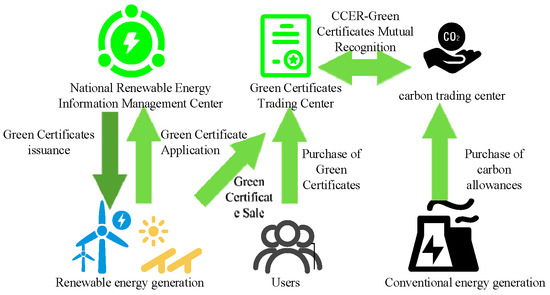
Figure 2.
Principle of the CET-GCT joint trading mechanism.
The following steps can be followed when implementing a joint CET-GCT trading mechanism:
- (1)
- Calculate the initial carbon credits of the microgrid system
The baseline method is used to allocate carbon emission credits for microgrid systems. This method determines the carbon emission credits of a microgrid system by setting a baseline and comparing it with the baseline based on the actual operation of the microgrid system. The specific calculation model is shown in Equation (42).
- (2)
- Determining the carbon emission reductions behind CCERs
According to the “Baseline Methodology for the Integration of Grid-connected Renewable Energy Projects,” issued by the National Development and Reform Commission of China in 2013, it is possible to determine the emission reduction contribution per MWh of renewable energy capacity. This is calculated using the “Regional Grid Baseline Emission Factor,” which reflects the average carbon emissions per unit of electricity generated in a given regional grid. Based on this factor, a carbon reduction benefit corresponding to the GCT can be calculated:
In the formula, represents the carbon emission reduction of CCER, also known as the carbon emission offset by green certificates; and represent the weights of the marginal emission factors of electricity and capacity, respectively, which reflect the respective importance of electricity and capacity in the calculation of carbon emission; and represent the marginal emission factors of electricity and capacity, respectively, which are the basic parameters for the calculation of carbon emission; and represents the green power of new energy quotas in the microgrid, also known as the power generated from renewable energy sources.
- (3)
- Determination of carbon allowances for microgrids after carbon–green certificate mutual recognition
After considering the carbon emissions behind the green certificates, which can directly affect the carbon allowance of the microgrid, Formula (41) can be rewritten as follows:
In the formula, is the carbon allowances for the eventual microgrid.
- (4)
- Analysis of the benefits of joint carbon–green certificate trading
Upon completion of the carbon–green certificate mutual recognition mechanism, this initiative will bring about positive benefits in many aspects. On the one hand, it can enable the carbon quota of microgrids to be effectively increased, thereby reducing the economic burden of microgrids on the carbon quota and enhancing their operational efficiency. On the other hand, this mechanism can also motivate power generation enterprises to purchase green certificates and promote the development and application of green energy. Despite the differences in market functions between the CET and the GCT mechanisms, their ultimate goals are the same, which are to promote new energy consumption and reduce carbon emissions. Through the joint trading of carbon–green certificates, these two mechanisms can complement each other and jointly promote a green and low-carbon energy development path.
3.4. Objective Function
Based on the economic requirements for the autonomous operation of multi-microgrid systems, this model is constructed in accordance with the fundamental principle of cost minimization. Specifically, it achieves optimal control of the total operating costs of each microgrid by synergistically optimizing the transaction costs of green certificates, carbon quota revenues, energy procurement costs, and equipment maintenance costs.
In the formula, is the cost of microgrid i when it operates alone; , , , and are the cost of microgrid interaction with the primary grid, operation and maintenance cost of internal equipment, load demand response cost, and purchased gas cost; is the price of natural gas for microgrids to external gas grids; and are the purchased and sold electricity price of the primary grid; , , and are the demand response cost coefficients of electric load transfer and curtailment and heat transfer; and , , and are the operation and maintenance cost coefficients of gas turbines, new energy sources, and storage equipment, respectively.
4. Model Solving
This paper assumes that each microgrid belongs to different stakeholders and can interact with neighboring microgrids for energy exchange, carbon quota trading, and profit distribution. Based on the Nash bargaining theory, a multi-microgrid cooperative operation optimization model is established, and the Nash bargaining solution can make the participants of the cooperative alliance obtain Pareto-optimal benefits.
In the formula, I is the number of microgrids participating in the cooperative alliance; is the operating cost of microgrids when operating independently, which is the Nash negotiation breaking point; and is the operating cost of microgrids when operating cooperatively.
We can convert the above model into a more tractable form to simplify the computational process.
It is worth noting that the Nash bargaining game model for multiple microgrids is essentially a non-convex, nonlinear optimization problem, which makes it difficult to solve directly. Therefore, we convert it into two subproblems that are easier to solve: the subproblem P of minimizing the cost of each microgrid subject’s electro-carbon interaction alliance and the subproblem Q of the rational redistribution of alliance benefits. By solving these two subproblems sequentially, we can obtain the optimal solution of the model.
The entire model calculation process is shown in Figure 3 below:
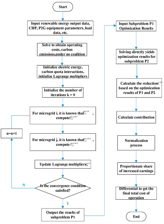
Figure 3.
Model solving flowchart.
4.1. Multi-Microgrid Cost Minimization Subproblem P
The core objective of the multi-microgrid subject alliance revenue-maximization subproblem P is to solve for the number of electric energy and carbon quota interactions between each microgrid subject when the alliance cost is minimized. With the P2P energy trading model, microgrids can flexibly choose to interact with other microgrids in terms of the electricity or carbon quota according to their own actual situation. To efficiently solve this kind of optimization problem with separable variables, we adopt the Alternating Direction Method of Multipliers (ADMM). The method is famous for its good convergence properties, concise form, and strong robustness.
In addition, to ensure that the interaction of electric energy and carbon quota among the multiple microgrid subjects is carried out in an orderly manner and to avoid an undesirable situation in which microgrid 1 and microgrid 2 simultaneously deliver electric energy or carbon quota to each other, we have specially added a restriction on the position of the switching state indication of the electric–carbon interaction among the microgrid subjects. This measure aims to ensure that the interaction of electricity and carbon quota is carried out on an orderly and reasonable basis to maintain stable operation and maximize the benefits of the multi-microgrid alliance:
In the formula, taking the electrical energy interaction of microgrids 1 and 2 as an example, is the transmission of electrical power from microgrid 1 to microgrid 2, is the transmission of electrical power from microgrid 2 to microgrid 1, is the electrical shared transmission status identification bit between microgrids 1and 2, 1 represents the transmission from microgrid 1 to 2, and 0 represents the transmission from microgrid 2 to 1.
4.1.1. Multi-Microgrid Body Power-Sharing Subproblem P1 Solving
With the introduction of the electricity sharing transaction variable between microgrids, although the output constraint interval of each device remains unchanged, its actual output value is dynamically adjusted to the new electricity balance state as the amount of energy interaction changes. The original electric balance equation (as shown in Equation (33)) of each microgrid within the system will also change as a result, transforming into the following new form:
In the formula, is the interacting electric power between microgrid i and microgrid j at moment t.
The costs incurred by microgrids through P2P power exchanges can be expressed as follows.
At the same time, the power interaction between microgrids exists as a coupling variable in this problem, and consistency constraints are also introduced to decouple the model when it is solved in a distributed manner.
The problem of minimizing the cost of a multi-microgrid coalition considering electrical energy interactions can be expressed as follows.
Following this, the specific steps for distributed solving based on the ADMM algorithm are as follows:
(1) The augmented Lagrange multiplier structural formula for constructing the objective function of the minimum operating cost of the coalition is as follows:
In the formula, is the sum of the augmented term cost of the first stage electrical sharing subproblem of the multi-microgrid in the nth generation and is the Lagrange multiplier, which is used to adjust the degree of constraint satisfaction during the iteration process; k represents the unique number corresponding to the combinators of microgrid i and microgrid j, which is used to distinguish between the different combinations of microgrids; set the augmented term penalty constant , which is used to control the penalty strength of constraint violation in the iteration process; n denotes the current number of iterations, and the maximum value is the preset upper limit of the number of iterations; at the time of initialization, the number of iterations is set to 1, and the number of power-sharing transactions between multiple microgrids is set to 0. The Lagrange multiplier is also set to 0, which serves as the starting point of the iterative computation.
(2) Decompose Formula (56) into a distributed iterative solution model for each microgrid (57), in which there are 2(N − 1) interactions within each microgrid, with representing the electrical energy interactions between the microgrid and other microgrids. Also, there are N-1 augmented Lagrange multipliers for each microgrid.
In the formula, is the sum of the augmented generalized costs of microgrid i in the first stage of the electrically shared subproblem in the nth generation.
(3) According to the Formulas (57) and (58) iteratively updating the power-sharing transaction variable , this process will continue until all 2N(N − 1) power interaction variables have been updated.
(4) Based on the new inter-microgrid power-sharing transaction volume , which is brought into the Formula (59), iteratively update all N(N − 1) Lagrange multipliers .
(5) Update the number of iterations n to record the current iteration progress.
(6) Determine whether the current objective function has converged.
If the convergence condition is satisfied, the iteration terminates; otherwise, it returns (58)–(60) and proceeds to the next round of iteration until the convergence condition is satisfied or the preset maximum number of iterations is reached, .
At this point, the solution of the coalition operation cost-minimization subproblem P1 of the electric energy interaction with the new operation cost of each microgrid body after the coalition is finished.
4.1.2. Solving the Carbon Sharing Subproblem P2
Since electricity and carbon quota interactions between microgrids belong to two different time scales, it is generally recognized in the existing literature that electricity transactions in microgrids are cleared hourly. In contrast, carbon transactions in microgrids are cleared daily. Based on this existing research foundation, in this paper, we set the scheduling range of electricity in hours and the scheduling range of the carbon quota in 1 day.
The revenue generated by Microgrid through the P2P carbon allowance exchange can be expressed as follows.
In the formula, is the amount of the carbon quota interacting between microgrid i and microgrid j. Similar to electricity trading, the costs incurred by each microgrid due to carbon quota trading cancel each other out when they are accumulated, so the optimal number of electricity interactions between microgrids obtained from subproblem P1 can be substituted into the Formula (63) to obtain the cost minimization problem of a multi-microgrid alliance considering carbon quota trading.
A straightforward solution to this problem allows the optimal number of carbon allowances to be traded to be determined and the total cost at this point to be calculated.
At this point, the optimal trading volume of electric carbon sharing among multiple microgrid subjects has been fully solved. To further enhance the satisfaction and fairness of sharing, a benefit redistribution link is usually needed to ensure that each microgrid can obtain reasonable benefits.
4.2. Solving the Profit Redistribution Subproblem Q
By solving subproblem 1, the optimal electricity interactions between microgrids and carbon quota interactions are obtained, which are substituted back into the Formula (51) to obtain the profit redistribution subproblem for multiple microgrids.
In addressing this sub-problem, we rely on the reduction in the total operating cost of the alliance compared to the total operating cost of the isolated multi-microgrid. This reduction represents the economic benefit of the multi-microgrid alliance by optimizing the interaction of electricity and carbon allowances. The reduction formula is as follows:
In the formula, is the amount of reduction.
In the process of redistributing the revenue, we followed the principle of distribution according to the contribution, i.e., the distribution of revenue is based on the actual contribution of each microgrid. At the same time, we also explicitly considered two types of allocation factors, namely time-sharing tariffs and electricity and carbon quotas, to ensure the fairness and reasonableness of the allocation. To this end, we construct the following contribution function to quantify the actual contribution of each microgrid in terms of the energy interaction and carbon reduction:
In the formula, is the microgrid , the initial contribution of the microgrid, and and are the electricity and carbon trading contributions of the microgrid, respectively. and are the price of buying and selling time-sharing electricity, and and are the price of buying and selling carbon allowances, respectively. is the sum of electricity sold by microgrid i to all other microgrids at moment t, and is the sum of electricity bought by microgrid i to all other microgrids at time t, is the sum of carbon allowances sold by microgrid i to all other microgrids, and is the sum of carbon allowances bought by microgrid i from all other microgrids.
To further incentivize the energy interaction behavior, we can consider transforming the original linear growth of contribution into an exponential growth pattern. Meanwhile, to prevent a power series that is too large from causing inconvenient calculations or distorted results, we can further carry out the normalization process to ensure the reasonableness and comparability of the data. After such processing, the final contribution of each microgrid subject will be able to reflect its actual contribution to the energy interaction more accurately. The specific calculation formula is as follows:
In the formula, is the final contribution of microgrid i to the multi-microgrid.
Up to this point, the benefits added as a result of the multi-microgrid alliance in subproblem P are distributed proportionally based on the contribution of each microgrid as a percentage of the total multi-microgrid contribution.
In the formula, is the microgrid that is due in subproblem Q.
Differencing the negotiation breaking point cost with the redistributed value of the cooperative alliance’s benefits yields the microgrid’s final actual total cost of operation after participating in the P2P electric carbon sharing , the final actual total cost of operation of .
5. Example Analysis
5.1. Model Setup
In this paper, a multi-microgrid system consisting of three different microgrids is used as a research object to simulate and validate the proposed method. Among them, Microgrid 1 and Microgrid 3 are wind farm microgrids in a particular region, while Microgrid 2 introduces P2G technology for decarbonization and improvement to enhance its effectiveness in carbon reduction. The PV, wind, and electric–heat load data used are derived from typical daily data in the region, while the microgrid parameters are set to reflect the different contradictions in source-load supply and demand that exist in each microgrid [35]. The structure and energy interactions of the multi-microgrid system are kept consistent with those shown in Figure 1. The primary electric and thermal load data for each microgrid, as well as the predicted power of wind and PV, are detailed in Appendix A. The operating parameters of the boiler and other equipment, as well as the related parameters of the arithmetic example, are listed in Table A1 in Appendix B. The arithmetic examples in this paper are simulated and analyzed using MATLAB R2024a software. The optimization cycle used in this paper is a typical 24 h day, and subsequent data are calculated within a scheduling cycle.
5.2. Introduction of P2G to Microgrids for Decarbonization
This section uses Microgrid 2, which incorporates P2G technology among the three microgrids, as an example to compare the costs and power output of Microgrid 2 with and without P2G technology. It compares and analyzes the achievements made before and after the introduction of P2G technology for low-carbon retrofitting in Microgrid 2. Table 1 demonstrates the results of the comparative analysis of Microgrid 2 on the day before and after the introduction of P2G for decarbonization. Before the retrofit, the actual carbon emission of Microgrid 2 was 67,044 kg, the carbon allowance revenue was 16,677 yuan, and the total operation cost was 19,577.0202 yuan. After the retrofit, P2G technology is introduced into Microgrid 2, which is capable of carbon capture and the mechanization of CO2, thus eliminating 22,632 kg of carbon emissions and reducing the actual carbon emissions to 44,412 kg, which is a 33.76% optimization compared to the pre-retrofit period. At the same time, the carbon quota revenue was also raised by 12,899 yuan, with a growth rate of 77.35%. It is worth noting that the total operational benefit of the system is 11,928.1962 yuan, with a cost reduction of 160.93%. This series of data shows that after the decarbonization of the microgrid individual, it has been significantly improved in terms of the carbon emission, carbon quota gain, and total operation cost.

Table 1.
Comparative analysis before and after the introduction of P2G in Microgrid 2 for low-carbon transformation.
Figure 4, Figure 5 and Figure 6, on the other hand, depict the electro-carbon power of Microgrid 2 before and after the retrofit when P2G low-carbon operation is introduced. By observing these two figures, it can be found that the output power of wind and PV, as well as the generating capacity of the thermal power plant, do not change significantly after the retrofit, the highest output point remains the same, and the output curve shows minor fluctuations, but the wind and solar utilization rate increases. The overall shape of the curves shows an increase in carbon capture and P2G power consumption after the retrofit, which indicates that the P2G technology requires more power to operate. However, at the same time, the amount of carbon captured by carbon capture is generally significantly increased, and the carbon capture power reaches a higher level, which can capture carbon emissions more effectively, thus realizing the goal of the decarbonized operation.
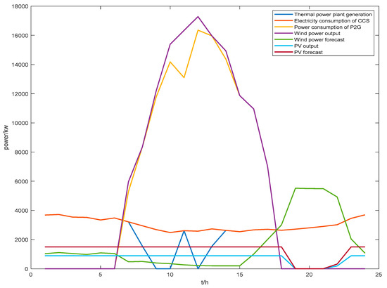
Figure 4.
Microgrid 2 introduces P2G to transform electric power maps.
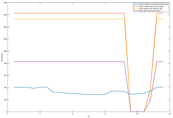
Figure 5.
Microgrid 2 introduces P2G to transform carbon power maps.
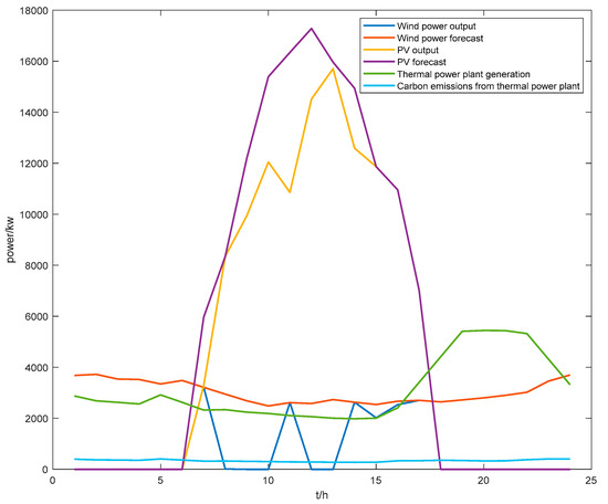
Figure 6.
Microgrid 2 electric carbon power before the retrofit.
5.3. Analysis of the P Results for the Subproblem of Maximizing the Benefits of Multiple Microgrids
This paper adopts the Nash game method to solve the energy–electricity interaction quantum problem P1 and the carbon quota interaction quantum problem P2 in the multi-microgrid alliance, mainly applying Formulas (52)–(63). The detailed process is illustrated in Figure 3. In the solution process, the convergence and superiority of the operating cost of the electric–carbon solution need to be analyzed in depth, and the complementarity of the energy interaction quantum among the central bodies of the microgrids, as well as the amount of wind and light abandoned and consumed, is also examined. In addition, the daily dispatch output of each device of the system, as well as the results of the electricity–carbon balance, is comprehensively evaluated to ensure the effectiveness and practicability of the solution method.
5.3.1. Convergence Analysis
Based on the operating costs corresponding to the negotiation breakdown points of each microgrid when operating independently, this section aims to validate the correctness and superiority of the distributed solution method using the Nash game for collaborating on the electricity sharing among the microgrid subjects.
Figure 7 shows the change in the error convergence curve, and it can be observed that when the number of iterations is close to 9, the curve begins to show a smooth trend, and convergence is successfully achieved at the 19th iteration. This result fully demonstrates that the distributed optimization algorithm used in this paper has excellent convergence performance and efficient computational ability, and at the same time, the algorithm can also meet the optimization requirements under the premise of protecting the privacy of each subject, showing good overall performance.
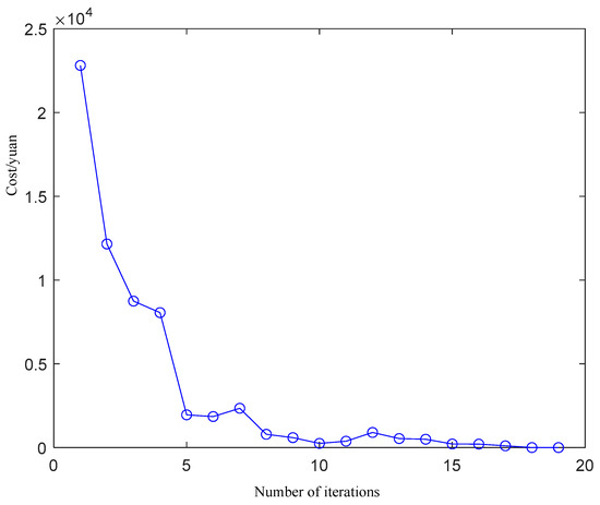
Figure 7.
Error convergence curves.
Figure 8a–c show the iterative results of the operating costs of Microgrid ①, Microgrid ②, and Microgrid ③, respectively, in the electric sharing subproblem. Through the iterative process, it can be observed that the operation cost of each microgrid gradually stabilizes. Figure 8d, on the other hand, shows the iterative results of the running cost of the coalition, which also realizes a leveling off after iteration, and this result proves the convergence of the distributed solution method.
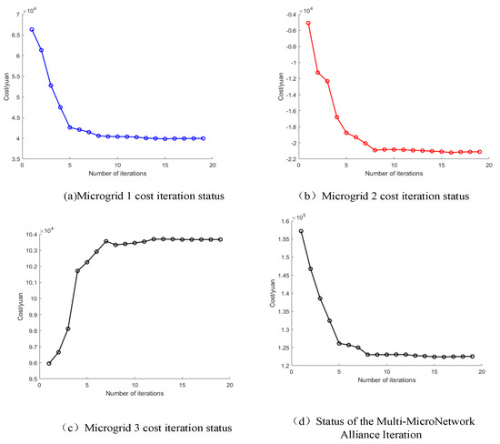
Figure 8.
Iteration results.
5.3.2. Complementarity Results Analysis of Energy Interactions Among Microgrid Subjects
Figure 9 illustrates the results of the electrical energy interaction between the microgrids. Microgrid 1 primarily relies on wind power. During the periods from 1:00 a.m. to 6:00 a.m. and from 5:00 p.m. to midnight, when wind conditions are favorable, Microgrid 1 sells electricity to other microgrids. During the periods from 7:00 a.m. to 4:00 p.m., when wind speeds are lower and wind power generation is insufficient, Microgrid 1 must purchase electricity from other microgrids. Microgrid 2 combines solar and wind power. During the periods from 8:00 a.m. to 4:00 p.m. and 10:00 p.m., when solar and wind power generation is high, Microgrid 2 sells excess electricity to supply other microgrids. During other periods, Microgrid 2 must purchase electricity. Microgrid 3 primarily relies on photovoltaic power generation. During the period from 8:00 a.m. to 4:00 p.m., when photovoltaic power generation is high, Microgrid 3 sells excess electricity to other microgrids. During nighttime periods with no sunlight and low photovoltaic power generation, Microgrid 3 must purchase electricity from other microgrids.
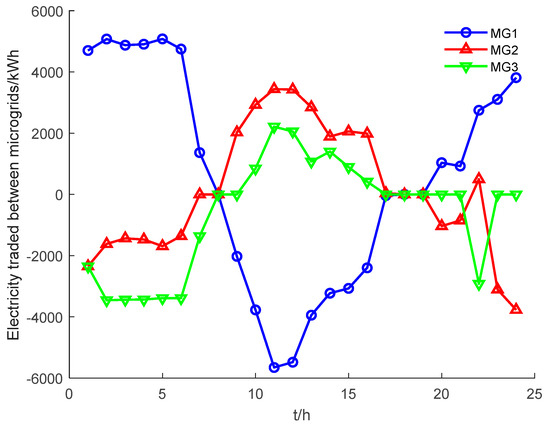
Figure 9.
Results of electricity trading between microgrids.
Figure 10 shows the results of the carbon quota interaction between micro-networks. The chart above shows that the method used in this paper ensures the equilibrium of carbon trading, and the local carbon trading market allows each microgrid to allocate carbon quotas reasonably according to energy consumption characteristics and power generation. Specifically, Microgrid 1 purchased a total of 13,045.87648 kg of the carbon allowance volume from Microgrid 2 and Microgrid 3. Microgrid 3, in turn, purchased 20,829.167493 kg of carbon allowances from Microgrid 2 and sold 3231.7152 kg of carbon allowances to Microgrid 1. In turn, Microgrid 2 sold a total of 30,643.32877 kg of carbon allowances to Microgrid 1 and Microgrid 3. Such a carbon trading model not only contributes to the carbon balance between microgrids but also further promotes the effective management of carbon emissions.
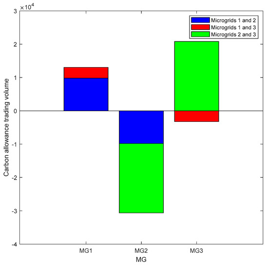
Figure 10.
Volume of carbon allowances traded between microgrids.
5.3.3. Analysis of the Daily Dispatch Output and Power–Heat Balance Results of the Microgrid 2 Equipment After the Alliance
Figure 11 and Figure 12 show the optimal scheduling strategy of electrical and thermal energy within the microgrid after Nash negotiation, using Microgrid 2 as an example. In Figure 11, it can be seen that during the period from 1:00 to 6:00, due to the relatively low electrical loads and the more abundant wind power generation at night, Microgrid 2 mainly obtains electrical energy through the discharge of the electrical storage devices and the wind power generation and trades electrical energy with the neighboring microgrids. During the period from 7:00 to 17:00, on the other hand, the electricity demand gradually increases with sunrise and the start of daily activities. Despite the relatively high electrical load, the PV output also peaks. The electric storage device is currently charged and sells electricity mainly to the grid and Microgrid 3 to enhance its efficiency. From 18:00 to 24:00 at night, wind power may continue to supply power to Microgrid 2, while PV generation gradually decreases. At this point, power demand peaks again, and the battery system begins discharging to meet the demand. In the event of a decrease in the renewable energy supply, thermal generation increases to fill the gap. When the power demand exceeds the total supply capacity of Microgrid 2, power is purchased from Microgrid 1 at this point, and power needs to be purchased again from the grid to meet the demand. Figure 12 then shows the primary way of obtaining thermal energy in Microgrid 2, i.e., the heat generated by the CHP units to maintain the thermal power balance within the microgrid. Combining the power output of each device in Figure 11 and Figure 12, it can be seen that the interaction between the microgrids and the energy storage strategy effectively smooths out the temporal and spatial contradiction between the source and load and realizes a higher economy. At the same time, this strategy also avoids the economic loss of the CHP unit due to low power operation or shutdown and shutdown, which significantly increases the flexibility of the system.
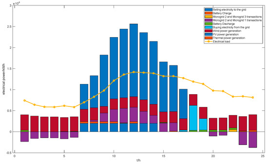
Figure 11.
Post-coalition Microgrid 2 electric power results diagram.
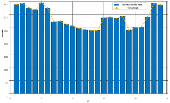
Figure 12.
Post-coalition Microgrid 2 thermal power balance diagram.
5.4. Analysis of the Benefits of Multi-Microgrid Electricity-Carbon Coupling Transactions
In the process of solving the coalition benefit maximization subproblem, the electric–carbon interactions are first obtained and substituted into the self-constructed asymmetric energy mapping contribution function as input parameters. This function takes into account multiple dimensions, such as the period, energy type, and supply/demand side, and is used to calculate the contribution of each microgrid accurately. Subsequently, based on this contribution, the increased benefits of the multi-microgrid alliance are redistributed more rationally. Formulas (64)–(68) were mainly applied in this process. The results of the redistribution are shown in Table 2, and a comparison of the benefits of each microgrid in the multi-microgrid system when trading in electricity–carbon coupling and when operating independently is also provided for a more in-depth analysis and discussion.

Table 2.
Results of rational redistribution of revenues from the multi-micronetwork alliance.
Table 2 demonstrates the changes in the operating costs of each microgrid after the end of the electric–carbon sharing operation. Specifically, the operating cost of Microgrid ① is significantly reduced from 47,786.1 yuan to 32,684 yuan, the operating cost of Microgrid ② is further reduced from −7189.66 yuan to −26,777 yuan, and the operating cost of Microgrid ③ is also slightly increased from 115,420 yuan to 121,652.3 yuan. Although the total cost of multi-microgrids realized a reduction in profit, there is still an imbalance in the distribution of benefits. To solve this problem, this paper redistributes the alliance benefits of the three multi-microgrid subjects. Specifically, the electric–carbon interaction information of the electric–carbon sharing result is first substituted into the asymmetric energy mapping contribution function to obtain the contribution ratio of Microgrids ①, ②, and ③. Subsequently, the benefits are distributed to each microgrid subject according to the contribution ratio of each subject, realizing the redistribution of benefits. After redistribution, the operating cost of micro-network ① is further reduced from 47,786.1 yuan to 33,951.1 yuan, the operating cost of micro-network ② is also reduced from −7189.66 yuan to −22,333.66 yuan, and the operating cost of micro-network ③ is significantly reduced to 106,102.9 yuan. This result shows that each micro-network receives the corresponding benefit according to its contribution, confirming the necessity and superiority of time-sharing asymmetric benefit redistribution.
5.5. Carbon Reduction Benefit Analysis of Electric Carbon Sharing in Multi-Microgrid Alliance
Table 3 presents an analysis of the carbon reduction benefits of the multi-microgrid alliance before and after the implementation of the electric carbon-sharing strategy. Specifically, the carbon emissions of Microgrid ① decrease from 86,159 kg to 76,523 kg, the carbon emissions of Microgrid ② decrease from 44,328 kg to 39,995 kg, and the carbon emissions of Microgrid ③ decrease from 86,371 kg to 70,125 kg. Overall, the total carbon emissions of the alliance realize a significant decrease from 217,178 kg to 186,643 kg, which is a decrease of 14.06%. This data fully proves that the Nash game-theory-based electric carbon-sharing strategy of the multi-microgrid alliance has significant environmental benefits in reducing carbon emissions.

Table 3.
Carbon reduction benefit analysis of electric–carbon bilayer sharing in a multi-microgrid consortium.
6. Conclusions
Against the background of the increasing share of renewable energy in the power system and in response to the demand for low-carbon and economic operation of the power system, this paper focuses on the multi-microgrid coupled with electricity–heat–gas and proposes a CHP unit operation model with CCS-P2G. First, this paper constructs a low-carbon coordinated operation model based on Nash game theory, considering electricity and carbon quota trading. Subsequently, to facilitate the solution, the model is decomposed into two subproblems: the microgrid alliance cost minimization subproblem and the cooperative benefit allocation subproblem. The ADMM algorithm is employed to solve the microgrid alliance cost minimization subproblem, thereby achieving optimal system configuration. In addressing the cooperative benefit allocation subproblem, an asymmetric negotiation model is constructed to ensure the fair distribution of benefits. Finally, the following conclusions are drawn through arithmetic example verification and analysis:
The multi-microgrid electricity and carbon sharing optimization model solved by the ADMM algorithm effectively safeguards the privacy and security of the participating subjects by only exchanging limited information on traded electricity and carbon quota among microgrids during the cooperation process. Meanwhile, the proposed algorithm shows good convergence performance.
The CHP-P2G-CCS synergistic operation mode can effectively reduce carbon emissions within the IES. With this mode, the carbon emission cost of the multi-energy microgrid is reduced by 33.76% compared to that of the CHP unit alone. It has positive significance for realizing the low-carbon economic operation of the system.
Compared with the microgrid’s independent operation mode, the whole system’s total benefit is improved by 38,296.1 yuan, and the carbon emission is reduced by 30,535 kg through the cooperative operation of electric–carbon coupling. This change helps promote the low-carbon economic operation of the system and realizes the double enhancement of the environmental and economic benefits.
The constructed multi-microgrid asymmetric bargaining-revenue-allocation model can realize the fair distribution of revenue after microgrid cooperation. The model ensures that microgrids with higher new energy generation capacity can obtain higher revenues in the energy sharing process, thus effectively stimulating the enthusiasm of each microgrid to participate in energy cooperation and encouraging distributed entities to increase the construction of their new energy generation facilities.
The conclusions of this study provide a reference basis for the planning and design of multi-microgrid systems and the optimization of power generation. Compared with traditional studies on the impact of markets or single markets on multi-microgrid systems, this study focuses on exploring the joint synergistic effects of green certificates and carbon trading on multi-microgrid systems. This demonstrates its foresight and practical application value in the current low-carbon economic environment. The multi-microgrid operation optimization model developed in this study, which takes into account green certificates and carbon trading, is primarily intended for operators directly responsible for multi-microgrid system operation decisions, integrated energy service companies, or power retailers providing energy management services, as well as power grid companies, dispatch institutions, and policy-making departments (such as the National Energy Administration and the Ministry of Ecology and Environment) concerned with regional energy and carbon-emission-reduction policies. For operators and service providers, the model serves as a decision-support tool. By integrating it into their energy management systems, they can utilize real-time source-load-storage data and market price signals to automatically generate optimal operational scheduling and joint trading strategies for green certificates and carbon quotas, thereby reducing total costs and enhancing environmental benefits. For power grid companies and policymakers, the model serves as a simulation platform to assess the impact of different green certificate and carbon trading policies on regional energy consumption, carbon emissions, and market behavior, providing a quantitative basis for operational guidance and policy design. The key to implementation lies in integrating the model algorithms into the corresponding management or simulation systems. The research conclusions have promoted the actual development of the microgrid field and guided the construction of low-carbon energy systems.
Future research should, in particular, provide for a consideration of the introduction of the impact of uncertainty factors, including the uncertainty of the electricity market price and the uncertainty of the new energy output, to make the model more complete, to improve further the model’s adaptive ability and the ability to withstand risks.
Author Contributions
X.X.: Conceptualization, Methodology, Formal analysis, Software, Validation, Data curation, Writing-original draft, Writing—Review and Editing, Visualization. J.X.: Data curation, Software, Writing—original draft. C.H.: Investigation, Validation. P.S.: Formal analysis, Writing—original draft, Validation. P.X.: Data curation, Writing—original draft, Validation. J.L.: Conceptualization, Writing—Review and Editing, Supervision, Project administration, Funding acquisition. All authors have read and agreed to the published version of the manuscript.
Funding
The authors declare that this study received funding from State Grid Hebei Electric Power Co., Ltd., the Project ID is B604JY240087.
Data Availability Statement
The original contributions presented in the study are included in the article, further inquiries can be directed to the corresponding author.
Conflicts of Interest
Author Pengfei Sun was employed by the company State Grid Hebei Electric Power Co., Ltd. The remaining authors declare that the research was conducted in the absence of any commercial or financial relationships that could be construed as a potential conflict of interest.
Appendix A. Microgrids Based on Electrical and Thermal Load Data and Wind and PV Output
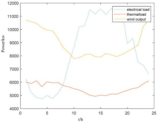
Figure A1.
Microgrid 1 data.
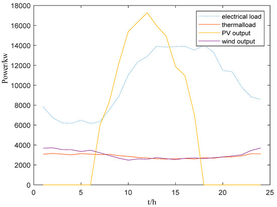
Figure A2.
Microgrid 2 data.
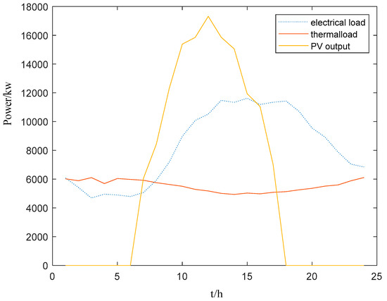
Figure A3.
Microgrid 3 data.
Appendix B. Operational Parameters of Microgrid Equipment

Table A1.
Arithmetic parameters.
Table A1.
Arithmetic parameters.
| Name | Numerical Value | Name | Numerical Value |
|---|---|---|---|
| Proportional limit of reducible electric power | 0.05 | Ideal gas consumption per unit of heat production for heat boilers | 9.7 |
| Proportional limit of transferable electric power | −0.1~0.1 | The ratio of actual to ideal efficiency of thermal boilers | 0.9 |
| Proportional limit of transferable thermal power | −0.1~0.1 | Carbon emissions per unit of heat production from heat boilers | 0.65 kg |
| Initial battery charge | 1000 kWh | Carbon emission factor for electricity production from cogeneration | 0.785 kg/kWh |
| Battery charging efficiency | 0.95 | Carbon emission factor for cogeneration heat production | 0.15 kg/kWh |
| Battery discharge efficiency | 0.96 | Carbon capture equipment power limits | 1000 kW |
| Lower battery charge limit | 500 kWh | Power limits for electricity-to-gas equipment | 1000 kW |
| Battery charge limit | 2500 kWh | Cogeneration power supply ceiling | 7000 kW |
| Battery charging power limit | 0~300 kW | The lower limit of cogeneration power supply | 0 kW |
| Battery discharge power limit | 0~300 kW | Thermoelectric coupling coefficient Kmin | 0.15 |
| Thermal boiler thermal power limit | 0~6500 kW | Thermoelectric coupling coefficient Kmax | 0.2 |
| A limit on the amount of electrical power that can be sold | 2000 kW | Thermoelectric coupling coefficient Kl | 0.85 |
| Purchased power limit | 10,000 kW | Cogeneration climbing constraints | 1000 kW |
| Gas-to-electricity ratio for electricity-to-gas operation | 0.55 | Unit price for heat transfer compensation | 0.016 yuan/kWh |
| Carbon capture operation carbon-to-electricity ratio | 0.55 | Maximum number of iterations | 100 |
| Carbon-to-electricity ratio for electricity-to-gas operation | 0.5 | Convergence accuracy of the alternating direction multiplier method | 0.001 |
| Unit price of natural gas | 3.5 yuan/m3 | Carbon storage and release efficiency | 0.97 |
| Electricity transfer compensation unit price | 0.3 yuan/kWh | Initial carbon load | 2000 kg |
| Electricity reduction compensation unit price | 0.3 yuan/kWh | Lagrange multiplier (math.) | 1 × 10⁻⁴ |
| Sgreen | 0.050 yuan/kWh | D | 10,000 kg |
| 0.0075 | 0.0025 | ||
| 1.0585 | 0.9066 |
References
- Yang, Q.; Zhang, B.; Bian, H.; Chen, K.; Duan, J. Reward and Penalty Mechanism Considering Uncertain Carbon Emission’s Green Certificates–Carbon Trading Power Planning. Electr. Eng. 2024, 107, 4169–4186. [Google Scholar] [CrossRef]
- Al-Shetwi, A.Q.; Hannan, M.A.; Jern, K.P.; Mansur, M.; Mahlia, T.M.I. Grid-Connected Renewable Energy Sources: Review of the Recent Integration Requirements and Control Methods. J. Clean. Prod. 2020, 253, 119831. [Google Scholar] [CrossRef]
- Reguieg, Z.; Bouyakoub, I.; Mehedi, F. Optimizing Power Quality in Interconnected Renewable Energy Systems: Series Active Power Filter Integration for Harmonic Reduction and Enhanced Performance. Electr. Eng. 2024, 106, 7755–7768. [Google Scholar] [CrossRef]
- Tajjour, S.; Singh Chandel, S. A Comprehensive Review on Sustainable Energy Management Systems for Optimal Operation of Future-Generation of Solar Microgrids. Sustain. Energy Technol. Assess. 2023, 58, 103377. [Google Scholar] [CrossRef]
- Zhang, J.; Liu, Z. Low Carbon Economic Dispatching Model for a Virtual Power Plant Connected to Carbon Capture System Considering Green Certificates-Carbon Trading Mechanism. Sustain. Energy Technol. Assess. 2023, 60, 103575. [Google Scholar] [CrossRef]
- Li, J.; Xiao, Y.; Lu, S. Optimal Configuration of Multi Microgrid Electric Hydrogen Hybrid Energy Storage Capacity Based on Distributed Robustness. J. Energy Storage 2024, 76, 109762. [Google Scholar] [CrossRef]
- Bokopane, L.; Kusakana, K.; Vermaak, H.; Hohne, A. Optimal Power Dispatching for a Grid-Connected Electric Vehicle Charging Station Microgrid with Renewable Energy, Battery Storage and Peer-to-Peer Energy Sharing. J. Energy Storage 2024, 96, 112435. [Google Scholar] [CrossRef]
- Salyani, P.; Nourollahi, R.; Zare, K.; Razzaghi, R. A Cooperative Game Approach for Optimal Resiliency-Oriented Scheduling of Transactive Multiple Microgrids. Sustain. Cities Soc. 2023, 89, 104358. [Google Scholar] [CrossRef]
- Du, X.; Yang, Y.; Guo, H. Optimizing Integrated Hydrogen Technologies and Demand Response for Sustainable Multi-Energy Microgrids. Electr. Eng. 2024, 107, 1–23. [Google Scholar] [CrossRef]
- Wang, Z.; Yu, X.; Mu, Y.; Jia, H.; Jiang, Q.; Wang, X. Peer-to-Peer Energy Trading Strategy for Energy Balance Service Provider (EBSP) Considering Market Elasticity in Community Microgrid. Appl. Energy 2021, 303, 117596. [Google Scholar] [CrossRef]
- Zhao, F.; Li, Z.; Wang, D.; Ma, T. Peer-to-Peer Energy Sharing with Demand-Side Management for Fair Revenue Distribution and Stable Grid Interaction in the Photovoltaic Community. J. Clean. Prod. 2023, 383, 135271. [Google Scholar] [CrossRef]
- Han, B.; Zahraoui, Y.; Mubin, M.; Mekhilef, S.; Korõtko, T.; Alshammari, O. Distributed Optimal Storage Strategy in the ADMM-Based Peer-to-Peer Energy Trading Considering Degradation Cost. J. Energy Storage 2024, 96, 112651. [Google Scholar] [CrossRef]
- Hu, D.; Ye, Z.; Gao, Y.; Ye, Z.; Peng, Y.; Yu, N. Multi-Agent Deep Reinforcement Learning for Voltage Control with Coordinated Active and Reactive Power Optimization. IEEE Trans. Smart Grid 2022, 13, 4873–4886. [Google Scholar] [CrossRef]
- Umar, A.; Kumar, D.; Ghose, T. Decentralized Energy Trading in Microgrids: A Blockchain-Integrated Model for Efficient Power Flow with Social Welfare Optimization. Electr. Eng. 2024, 107, 1–19. [Google Scholar] [CrossRef]
- Wang, Z.; Hou, H.; Zhao, B.; Zhang, L.; Shi, Y.; Xie, C. Risk-Averse Stochastic Capacity Planning and P2P Trading Collaborative Optimization for Multi-Energy Microgrids Considering Carbon Emission Limitations: An Asymmetric Nash Bargaining Approach. Appl. Energy 2024, 357, 122505. [Google Scholar] [CrossRef]
- Albert, B.K.; Jothimani, G. Multiple Microgrid Sustainable Energy Management Employing Ensemble Deep Neural Network to Enhance QoS in Stealthy False Data. Electr. Eng. 2024, 106, 4309–4326. [Google Scholar] [CrossRef]
- Alizadeh Bidgoli, M.; Ahmadian, A. Multi-Stage Optimal Scheduling of Multi-Microgrids Using Deep-Learning Artificial Neural Network and Cooperative Game Approach. Energy 2022, 239, 122036. [Google Scholar] [CrossRef]
- Pang, Y.; Hu, G. Nash Equilibrium Seeking in N -Coalition Games via a Gradient-Free Method. Automatica 2022, 136, 110013. [Google Scholar] [CrossRef]
- Cheng, S.; Zuo, X.; Wei, Z.; Ni, K.; Wang, C. Nash Bargaining-based Cooperative Game for Distributed Economic Scheduling of Microgrid with Charging-Swapping-Storage Integrated Station. Int. J. Energy Res. 2022, 46, 23927–23938. [Google Scholar] [CrossRef]
- Ma, T.; Pei, W.; Deng, W.; Xiao, H.; Yang, Y.; Tang, C. A Nash Bargaining-Based Cooperative Planning and Operation Method for Wind-Hydrogen-Heat Multi-Agent Energy System. Energy 2022, 239, 122435. [Google Scholar] [CrossRef]
- Chen, W.; Wang, J.; Yu, G.; Chen, J.; Hu, Y. Research on Day-Ahead Transactions between Multi-Microgrid Based on Cooperative Game Model. Appl. Energy 2022, 316, 119106. [Google Scholar] [CrossRef]
- Zhong, X.; Liu, Y.; Xie, K.; Xie, S. A Local Electricity and Carbon Trading Method for Multi-Energy Microgrids Considering Cross-Chain Interaction. Sensors 2022, 22, 6935. [Google Scholar] [CrossRef] [PubMed]
- Cai, W.; Kordabad, A.B.; Gros, S. Energy Management in Residential Microgrid Using Model Predictive Control-Based Reinforcement Learning and Shapley Value. Eng. Appl. Artif. Intell. 2023, 119, 105793. [Google Scholar] [CrossRef]
- Pan, Y.; Ju, L.; Yang, S.; Guo, X.; Tan, Z. A Multi-Objective Robust Optimal Dispatch and Cost Allocation Model for Microgrids-Shared Hybrid Energy Storage System Considering Flexible Ramping Capacity. Appl. Energy 2024, 369, 123565. [Google Scholar] [CrossRef]
- Muros, F.J.; Maestre, J.M.; Ocampo-Martinez, C.; Algaba, E.; Camacho, E.F. A Game Theoretical Randomized Method for Large-Scale Systems Partitioning. IEEE Access 2018, 6, 42245–42263. [Google Scholar] [CrossRef]
- Qin, M.; Xu, Q.; Liu, W.; Xu, Z. Low-carbon Economic Optimal Operation Strategy of Rural Multi-microgrids Based on Asymmetric Nash Bargaining. IET Gener. Transm. Distrib. 2024, 18, 24–38. [Google Scholar] [CrossRef]
- Wang, Y.; Qiu, J.; Tao, Y.; Zhao, J. Carbon-Oriented Operational Planning in Coupled Electricity and Emission Trading Markets. IEEE Trans. Power Syst. 2020, 35, 3145–3157. [Google Scholar] [CrossRef]
- Kang, C.; Zhang, Z.; Kudashev, S.; Liu, M.; Zhang, Q.; Pan, J. Operation Optimization Strategy of Multi-Microgrids Energy Sharing Based on Asymmetric Nash Bargaining. Bull. Sci. Pract. 2022, 8, 334–353. [Google Scholar] [CrossRef]
- Lang, Y.; Xu, D.; Liu, S.; Hu, L. A Scheduling Model for Wind Power Consumption Considering Source-Charge Coordination of Combined Heat and Power System in Low-Carbon Environment. IOP Conf. Ser. Mater. Sci. Eng. 2020, 752, 012004. [Google Scholar] [CrossRef]
- Wang, X.; Jin, W.; Xu, B.; Wang, K. Volatility in Carbon Futures Amid Uncertainties: Considering Geopolitical and Economic Policy Factors. J. Futures Mark. 2025, 45, 308–325. [Google Scholar] [CrossRef]
- Wang, G.; Zhang, Q.; Su, B.; Shen, B.; Li, Y.; Li, Z. Coordination of Tradable Carbon Emission Permits Market and Renewable Electricity Certificates Market in China. Energy Econ. 2021, 93, 105038. [Google Scholar] [CrossRef]
- Wang, S.; Wang, X.; Zhang, S. Game Analysis of Electricity Market Considering Carbon Emission and Green Certificate Trading. In Proceedings of the 2023 3rd Power System and Green Energy Conference (PSGEC), Shanghai, China, 24–26 August 2023; IEEE: Shanghai, China, 2023; pp. 115–120. [Google Scholar]
- Hou, H.; Ge, X.; Yan, Y.; Lu, Y.; Zhang, J.; Dong, Z.Y. An Integrated Energy System “Green-Carbon” Offset Mechanism and Optimization Method with Stackelberg Game. Energy 2024, 294, 130617. [Google Scholar] [CrossRef]
- Wang, H.; Wang, C.; Zhao, L.; Ji, X.; Yang, C.; Wang, J. Multi-Micro-Grid Main Body Electric Heating Double-Layer Sharing Strategy Based on Nash Game. Electronics 2023, 12, 214. [Google Scholar] [CrossRef]
- Dong, L.; Li, Y.; Chen, S.; Qiao, J.; Pu, T. Multi-Microgrid Cooperative Game Optimization Scheduling Considering Multiple Uncertainties and Coupled Electric-Carbon Trading. Trans. China Electrotech. Soc. 2024, 32, 2635–2651. [Google Scholar] [CrossRef]
Disclaimer/Publisher’s Note: The statements, opinions and data contained in all publications are solely those of the individual author(s) and contributor(s) and not of MDPI and/or the editor(s). MDPI and/or the editor(s) disclaim responsibility for any injury to people or property resulting from any ideas, methods, instructions or products referred to in the content. |
© 2025 by the authors. Licensee MDPI, Basel, Switzerland. This article is an open access article distributed under the terms and conditions of the Creative Commons Attribution (CC BY) license (https://creativecommons.org/licenses/by/4.0/).