Article

A Numerical Study on the Influence of an Asymmetric Arc on Arc Parameter Distribution in High-Current Vacuum Arcs

School of Electrical Engineering, Xi’an University of Technology, Xi’an 710048, China
*
Author to whom correspondence should be addressed.
Energies 2025, 18(15), 4025; https://doi.org/10.3390/en18154025
Submission received: 16 June 2025 / Revised: 21 July 2025 / Accepted: 24 July 2025 / Published: 29 July 2025
(This article belongs to the Special Issue Simulation and Analysis of Electrical Power Systems)

Abstract

During high-current vacuum arcing, asymmetric arcing with off-center plasma columns may occur due to stochastic discharge initiation and mechanical motion, receiving less research attention than symmetric arcing. The objective of this paper is to numerically analyze the influence law of asymmetric arc ignition on arc parameters. For 60 mm diameter contacts, three arc conditions of symmetric arcing, 33% arc offset, and 67% arc offset were modeled. The results show that the arc offset causes asymmetry in the arc’s distribution. For 33% offset, the pressure and number density on the side away from the root of the arc is about 50% of root values, while these parameters fall below 20% for the 67% offset. Simultaneously, arc offset elevates peak parameter values: under 33% offset, maxima for ion pressure, ion density, ion temperature, electron temperature, and current density rise 12%, 11%, 6%, 6%, and 14% versus symmetric arcing; during 67% offset, these escalate significantly to 67%, 61%, 12%, 18%, and 47%. This study contributes to providing reference for the analysis of vacuum interruption processes under asymmetric arcing conditions.

1. Introduction

Vacuum circuit breakers possess the advantages of environmental friendliness, flexible installation configurations, simple structure, and ease of maintenance, making them excellent power fault interruption equipment for constructing environmentally friendly power systems [1,2,3]. Currently, vacuum switches are finding wide application in medium-voltage power systems and are rapidly advancing towards high-voltage power systems.
The short-circuit current interruption capability is the core technical indicator of vacuum switches. During the vacuum interruption process, the vacuum arc delivers a large amount of energy to the anode within a short time, causing a rapid temperature rise in the anode material. When the energy is sufficiently large, melting occurs on the anode surface, even resulting in a molten pool. After severe anode erosion occurs, anode metal vapor is continuously released into the arc column region, compromising the dielectric strength of the vacuum medium. Furthermore, after the current zero moment, the anode becomes the cathode and the eroded contact surface becomes prone to electrical discharge phenomena. Consequently, the arc evolution process plays a pivotal role in the vacuum interruption capability [4,5,6].
The study of the arc evolution process has consistently been a focal point in vacuum switch research. Current research on vacuum arcs encompasses both experimental studies and simulation analysis. Experimental work primarily utilizes a high-speed camera to capture images of the vacuum arc [7,8,9,10]. This approach has yielded insights into the transition rules governing the vacuum arc under different discharge modes and anode activity modes, the evolution process of the vacuum arc under magnetic field, and the interaction between the vacuum arc and the contacts. In recent years, the application of spectroscopic diagnostics to vacuum arcs has advanced significantly [11,12,13]. Using this technology, microscopic parameters such as contact temperature and arc parameters have been acquired.
Due to the special nature of the high-current vacuum discharge, precise diagnosis of vacuum arcs on a large scale has high requirements for experimental equipment. Consequently, simulation studies serve as an effective means for the arc analysis [14,15,16]. Current vacuum arc simulations primarily encompass fluid modeling and hybrid modeling [17,18,19,20,21,22,23,24,25,26]. For high-current vacuum arcs, fluid simulations could obtain plasma parameters during the arcing process. Particle simulations facilitate the analysis of the vacuum arc from a discrete media perspective, especially under low-current conditions. Meanwhile, the interaction between the arc and the electrode surfaces constitutes a key focus of simulation studies.
Research on vacuum arcs is predominantly conducted under the assumption of uniform burning of the arc within the arc column region. However, asymmetric arcing situations, where the arc root is not positioned at the center of the contacts, frequently occur in vacuum switches [19,24,27]. Potential causes for the occurrence of asymmetric arcing may include, for instance, asymmetries arising during the manufacturing process of the interrupter chamber, the influence of contact surface morphology, and the influence of external mechanical vibrations. The arc parameters undergo significant changes during lateral arcing events. Currently, the influence of such arcs remains inadequately explored.
Therefore, the research objective of this paper is to analyze the parameter variations in a vacuum arc in an asymmetric ignition state. The arc model was established based on magnetohydrodynamics. For a typical medium-voltage vacuum arc firing condition, symmetrical arcing, 33% minor arc offset case, and 67% severe arc offset cases were selected for modeling. The inhomogeneity of the arc offset on the arc parameters was analyzed, and the maximum values of the arc parameters for different arc-firing cases were also compared.

2. Vacuum Arc Model

2.1. Governing Equations

The high current vacuum arc comprises the cathode region, arc column region, and anode region. The computational domain of this model exclusively encompasses the arc column plasma. Within this region, the Debye radius measures approximately 10−7 m, substantially smaller than the interrupter chamber dimensions. Consequently, the arc column plasma qualifies as fully ionized plasma. The contact material in the model is copper; thus, the modeled particles are copper ions and electrons. It is noted that the cathode mixing zone serves as the boundary condition for the arc column model. Therefore, cathode spot phenomena and associated processes—including particle acceleration and ionization—are excluded from this study.
In high-current vacuum arcs, the mean collision time of electrons is approximately 10−11 s, whereas their transit time from cathode to anode is approximately 10−7 s. For ions, the mean collision time is approximately 10−9 s, while their cathode-to-anode transit duration measures approximately 10−6 s. Since the collision times for both species are substantially shorter than their respective transit durations, vacuum arc plasma can be effectively analyzed using fluid dynamics methodologies. In addition, the pressure of the vacuum arc is not very high (on the order of 103~104 Pa), and the temperature is not very low (on the order of 103~104 K); therefore, the ideal gas assumption can be used to describe the vacuum arc.
In high-current vacuum arcs, the relaxation time of arc plasma is extremely short, significantly shorter than the variation rates of both the arc current and the contact gap. Consequently, in 50 Hz power systems, the vacuum arc can be considered to operate in a quasi-steady-state mode.
The ion number density is obtained from Equation (1).
( n i u i ) = 0
The Debye length in the vacuum arc is significantly smaller than the contact assembly dimensions, permitting the assumption that the arc is a fully ionized plasma. Thus, the electron number density is obtained from Equation (2).
n e = z i n i
The ion velocity is obtained from Equation (3).
( m i n i u i u i ) = p i p e + ( e n e ( u i u e ) × B ) + F ei + F ie
The electron velocity is obtained from Equation (4).
j = z i n i ( u i u e )
The current density is obtained from Equations (5) and (6).
μ 0 j = × B
1 μ 0 σ 2 B = × ( u e × B ) + × ( 1 n e e p e ) + × ( α 1 k e T e ) 1 σ 2 ( j × σ )
The ion temperature is obtained from Equation (7).
( u i ( 3 2 n i k T i + 1 2 n i m i u i 2 + p i ) ) = q i + Q ie
The electron temperature is obtained from Equation (8).
( u e ( 3 2 n e k T e + 1 2 m e u e 2 + p e ) ) = q e + Q ei + Q c
The parameters involved in Equations (1)–(8) are
F ie = F ei = z i n i m e m i m e + m i ν ei ( u e u i ) + α 1 z i n i k T e
Q ie = Q ei = 3 m e n e ν ei m i k ( T e T i )
q e = λ e T e α 1 n e k T e ( u i u e )
λ e = α 2 k 2 n e T e m e ν ei
q i = λ i T i
λ i ( T i T e ) 5 2 ( m e m i ) 1 2 λ e
For the definitions of symbols representing physical quantities in the paper, please refer to the Abbreviations Section.

2.2. Boundary Conditions

To analyze the arcing characteristics of asymmetric vacuum arcs, a three-dimensional Cartesian coordinate system is implemented with the cathode center established as the coordinate origin. The positive z-direction is oriented from the cathode toward the anode. The computational model’s boundary conditions consist of cathode boundary conditions, lateral boundary conditions, and anode boundary conditions.
In the vacuum arc, the cathode supplies arc particles and serves as the inlet boundary for the magnetohydrodynamics model of the arc. At lower arc currents, the vacuum arc flow is supersonic. At higher currents, the flow becomes subsonic. The short-circuit current studied in this paper represents a typical case of high-current vacuum arc. According to subsonic computational fluid dynamics principles, a saturation pressure condition must be applied at the cathode inlet boundary. At the same time, the ion temperature and electron temperature on the cathode side are set to 3 eV [17].
During short-circuit current interruption in a vacuum switch, the arc distribution at the cathode inlet is nonuniform across the contact surface. Arc imaging reveals cathode spots exhibiting maximal size at the center with progressive radial attenuation. To characterize this inhomogeneous current distribution at the cathode boundary, a two-dimensional Gaussian distribution of current density profile is implemented per prior research, with the central density prescribed at twice the area-averaged value. This distribution and saturation pressure together determine the arc density and velocity on the cathode side. At the cathode arc root, the arc current density attains its maximum value, while the ion velocity is set at approximately 1000 m/s.
For arcing conditions where the arc root deviates from the cathode center, the Gaussian distribution center is aligned with the actual arc root position. In the cathode X-Y plane, for symmetric arcing, the center coordinates are (0, 0, 0), and for an arc root offset by 10 mm from cathode center, the center coordinates become (0.01, 0, 0). The current density attenuation rate from center to periphery remains identical to symmetric cases. Consequently, the density at the arc root exhibits a marginal increase compared to symmetric arcing conditions.
Under the applied axial magnetic field of 5 mT/kA specified in this study, radial expansion of the arc column is constrained, resulting in arc morphology parallel to the contact boundaries. Consequently, the arc plasma velocity at side boundaries is prescribed as tangential to the contact surfaces. Adiabatic conditions are imposed at lateral boundaries to eliminate thermal exchange between the arc column and external vacuum environment.
In high-current vacuum arcs, the anode functions as the recipient of the arc. Arc energy elevates the anode temperature. Sufficient energy deposition may induce anode evaporation or particle spluttering. This study focuses exclusively on the arc column region. Anode processes are excluded from the computational model, with the anode configured solely as a passive recipient of the arc.
Consistent with subsonic compressible flow theory, the outlet fluid boundary is specified at Mach number unity. To satisfy the current continuity principle, an anode sheath layer is implemented between the arc column and anode, governed by Equation (15). The anode sheath layer induces a marked reduction in electron temperature at the anode interface.
ϕ sh = k T e e ln j ez j eth
In this work, the model was implemented within the ANSYS Fluent (version 2020) software framework with secondary development incorporating electromagnetic field equations into the fluid dynamics module. The mesh configuration comprises approximately one million grid cells, with a single simulation requiring approximately 10 h to complete.

3. Simulation Results

This study conducts simulation analysis using discharge parameters representative of medium-voltage vacuum interrupters: 60 mm contact diameter, 2.0 m/s average opening velocity, and 20 kA peak arc current. Three arc root configurations are modeled: (1) symmetric arcing with arc root at (0, 0, 0); (2) moderate 33% off-center arcing with root at (0.01, 0, 0); (3) severe 67% off-center arcing with root at (0.02, 0, 0). Analysis in this work is performed at the peak current of 20 kA with 10 mm instantaneous contact gap.

3.1. Number Density and Pressure

Figure 1 displays the ion number density distribution of the arc in the xz-plane. As the arc root offset is configured along the x-coordinate axis, the influence of asymmetric arcing on the ion density distribution is clearly visible in this plane.
Figure 1a illustrates the ion number density distribution under symmetric arcing conditions. As shown, the ion number density exhibits a symmetric profile, reaching its maximum value of 18.3 × 10²¹ m−3 at the cathode center and gradually decreasing toward the contact edges and anode side.
Figure 1b depicts an arcing state with 33% arc center offset with arc root coordinates at (0.01, 0, 0). The ion number density achieves its peak value of 20.4 × 10²¹ m−3 at the arc root and displays asymmetry in the xz-plane. The density values in the positive x-axis region are significantly higher than those in the negative x-axis region.
Figure 1c shows an arcing state with severe 67% arc center offset with arc root coordinates at (0.02, 0, 0). The ion number density predominantly exceeds 15 × 1021 m−3 along the positive x-axis, while rapidly decreasing below 15 × 1021 m−3 along the negative x-axis. The maximum density value of 29.4 × 10²¹ m−3 is obtained at the arc root.
Figure 1 demonstrates that arc offset affects ion number density throughout the entire arc column region. Figure 2 illustrates the ion number density distribution in the yz-plane. As depicted, the number density exhibits symmetric distribution in the yz-plane. Greater arc offset correlates with reduced number density in the yz-plane. At the cathode center, the symmetric arcing condition yields an ion number density of 18.3 × 10²¹ m−3. Under 33% arc offset, the density measures 17.2 × 10²¹ m−3, while at 67% arc offset, it decreases to 16.6 × 10²¹ m−3.
Figure 3 presents the ion pressure distribution in the xz-plane. The data show that variations in arc root position directly influence the arc pressure distribution in the arc column region. Figure 3a corresponds to symmetric arcing, where ion pressure exhibits uniform distribution in the xz-plane with the maximum pressure of 9750 Pa at the cathode center, gradually decreasing toward contact edges and the anode. Figure 3b depicts 33% arc offset conditions, showing pressure bias toward the arc root at (0.01, 0, 0) with a peak value of 10,900 Pa. Figure 3c represents severe 67% arc offset conditions with the arc root at (0.02, 0, 0), where ion pressure becomes highly concentrated along the positive x-axis with a maximum value of 16,500 Pa at the arc root, while pressure at the symmetric negative coordinate (−0.02, 0, 0) decreases to approximately 3000 Pa.
Figure 4 illustrates the ion pressure distribution in the yz-plane. As depicted, since arc displacement is configured along the positive x-axis, the ion pressure distribution maintains symmetry about the coordinate axes under all three operating conditions. Furthermore, the ion pressure in the yz-plane exhibits a gradual reduction as arc deviation intensifies. For symmetric arcing, the cathode-center ion pressure measures 9750 Pa. Under 33% arc offset conditions, this value decreases to 9010 Pa at the cathode center. In severe 67% arc offset conditions, the value further diminishes to 8510 Pa.

3.2. Arc Temperature

The relationship between ion number density and ion pressure in Section 3.1 is related to ion temperature according to the ideal gas equation. This section analyzes the ion temperature and electron temperature of the arc.
Figure 5 illustrates the ion temperature distribution in the xz-plane. As shown, asymmetric arc erosion significantly affects both the maximum value and distribution of ion temperature. In Figure 5a of uniform arcing condition, ion temperature exhibits symmetric distribution with a maximum value of 57,500 K near the anode center. For Figure 5b with 33% minor arc offset, the region of elevated ion temperature aligns with the arc displacement, peaking at 60,800 K above the arc root near the anode. Under Figure 5c with 67% severe arc offset, ion temperature distribution displays significant anisotropy, with values along the positive x-axis substantially exceeding those on the negative x-axis. Temperature particularly escalates above the arc root, reaching a maximum of 69,000 K.
As shown in Figure 5, arc displacement shifts the high-temperature region toward the positive x-axis, which is also evidenced by the yz-plane ion temperature distribution in Figure 6. In the yz-plane, ion temperature exhibits symmetric distribution under all three operating conditions, with temperatures near the anode consistently higher than those near the cathode. Ion temperature decreases progressively with increasing arc offset severity: for symmetric arcing, the peak temperature is 57,500 K; for 33% minor arc offset, the peak temperature is 50,900 K; and for 67% severe arc offset, the peak temperature is 40,700 K.
In the arc model presented in this paper, electron temperature differs from ion temperature. Figure 7 displays the electron temperature distribution in the xz-plane. Due to energy exchange between electrons and ions, electron temperature distribution exhibits similarity to that of ion temperature. Joule heating primarily affects electrons in the vacuum arc, resulting in electron temperature being slightly higher than ion temperature. Meanwhile, electron temperatures decrease marginally at the anode surface due to the anode sheath effect.
As shown in Figure 7, for uniform arcing conditions, the peak electron temperature of 67,700 K occurs in the arc column region near the anode. For 33% minor arc offset conditions, electron temperatures are higher on the positive x-axis, peaking at 71,250 K above the arc root at (0.01, 0, 0). Under 67% severe arc offset conditions, electron temperatures along the positive x-axis significantly exceed those on the negative x-axis, with a maximum temperature of 80,100 K.
Figure 8 presents the electron temperature distribution in the yz-plane. Since arc offset occurs along the x-axis, the distribution aligns with the ion temperature pattern in Figure 6, exhibiting uniformity. Electron temperatures are consistently slightly higher than ion temperatures across conditions. In Figure 8a with uniform arcing condition, the peak temperature reaches 67,700 K; for Figure 8b with 33% minor arc offset, it measures 58,830 K; for Figure 8c with severe arc offset, it decreases to 45,400 K.

4. Discussion

Analysis of the preceding arc plasma parameters reveals that asymmetric arcing forces plasma compression toward the offset side, elevating key parameters, including density, pressure, and temperature, as well as intensifying the constriction state of the arc. Using current density as the representative parameter, this section analyzes asymmetric arcing effects on arc contraction.
During vacuum arc flow from cathode to anode, axial current density jz sharply increases as arc constriction progresses. To analyze how arc offset affects this parameter, Figure 9 presents jz distributions along the x-axis at three critical positions: cathode surface, arc column centerline, and anode surface. The negative values of jz originate from the defined coordinate system where the anode resides at positive z-direction, making the current flow direction negative along the z-axis.
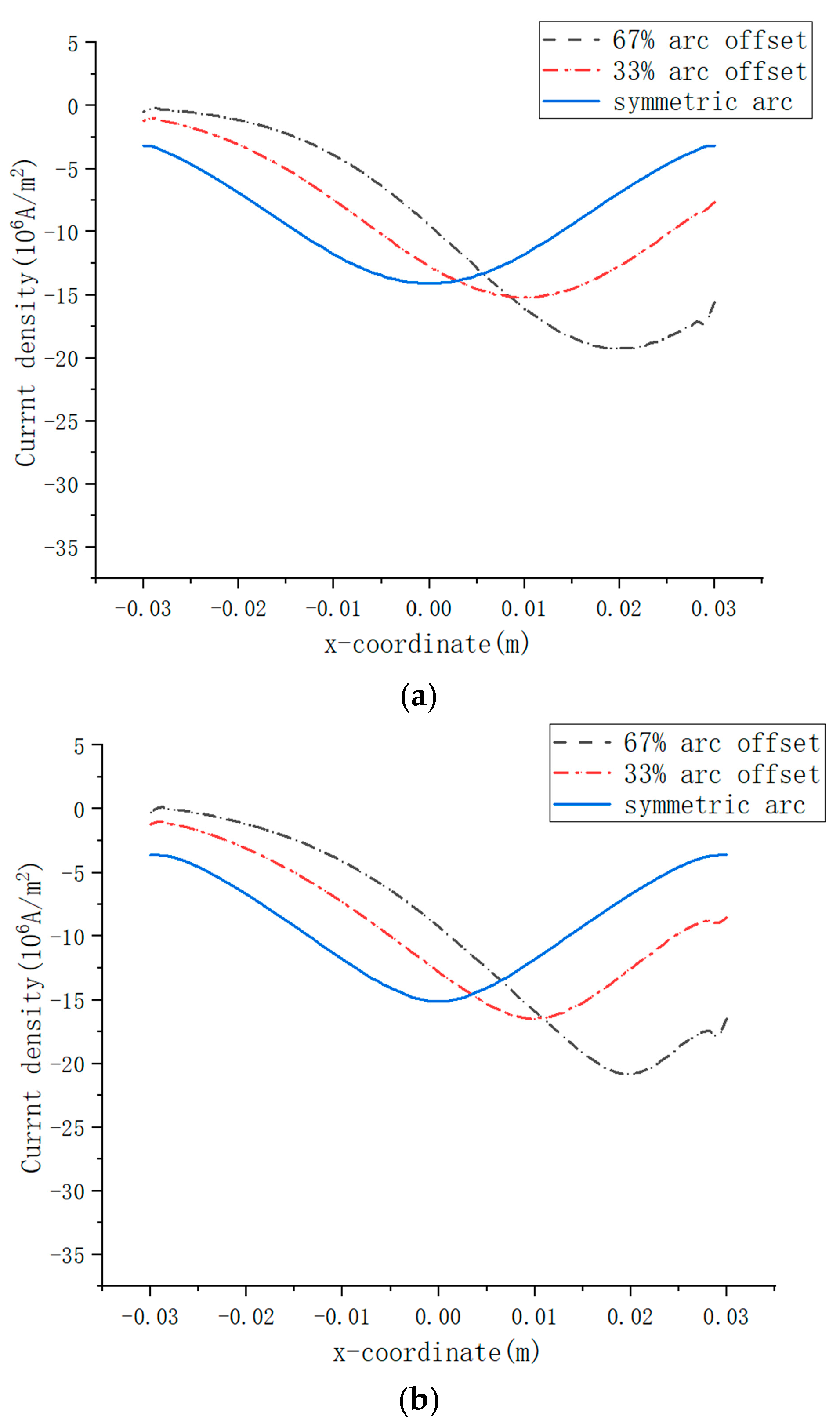
When arc offset occurs, high-speed imaging reveals that the arc plasma markedly concentrates toward the offset side, resulting in substantially higher current density at this location compared to the symmetrical arcing. In the cathode boundary conditions defined in this study, the current density attenuates toward the arc periphery at an identical decay rate across the cathode surface. Consequently, the more obvious the offset of the arc root, the higher the current density at the arc root. This modeling approach is consistent with the intensified current constriction observed in arc images under offset conditions.
Figure 9a depicts the cathodic axial current density profile, where arc displacement induces lateral shifting of the current density distribution with concurrent peak value enhancement. For symmetric arcing, the current density peaks at the cathode center with 14.1 × 10⁶ A/m2. At 33% arc offset, the peak value reaches 15.2 × 10⁶ A/m2 at the displaced arc root position. Under 67% offset, the current density maximum increases to 19.2 × 10⁶ A/m2 while being laterally offset by 0.02 m from the cathode center.
Figure 9b presents the axial current density profile at the arc column centerplane. The distribution mirrors the cathodic pattern but exhibits elevated peak magnitudes. Compared to the cathode surface, the current density maximum increases to 15.1 × 10⁶ A/m2 for symmetric arcing. Under 33% arc offset, the peak value rises to 16.5 × 10⁶ A/m2. At 67% arc offset, the maximum further escalates to 20.8 × 10⁶ A/m2.
Figure 9c displays the axial current density profile at the anode surface. The distribution exhibits marked constriction compared to the arc column centerplane, indicating intensified arc convergence in the near anode half of the interelectrode gap. For symmetric arcing, the current density maximum escalates to 22.1 × 10⁶ A/m2. Under 33% arc offset, the peak value rises to 25.1 × 10⁶ A/m2. At 67% offset, the maximum surges to 32.4 × 10⁶ A/m2.
The anode current density reflects the thermal loading on the anode induced by arc constriction. In this model, the mean current density is 7.1 × 10⁶ A/m2. During symmetric arcing, the peak anode current density reaches 3.1 times the mean current density. For 33% arc offset, the peak increases to 3.6 times the mean. At 67% offset, the value surges to 4.6 times.
As evidenced by plasma parameters in Figure 1, Figure 2, Figure 3, Figure 4, Figure 5, Figure 6, Figure 7 and Figure 8 and current density profiles in Figure 9, arc root displacement induces asymmetric plasma distributions. To quantify this effect, plasma parameters on the arc root along the positive semi-axis and corresponding mirrored locations along the negative semi-axis are statistically analyzed.
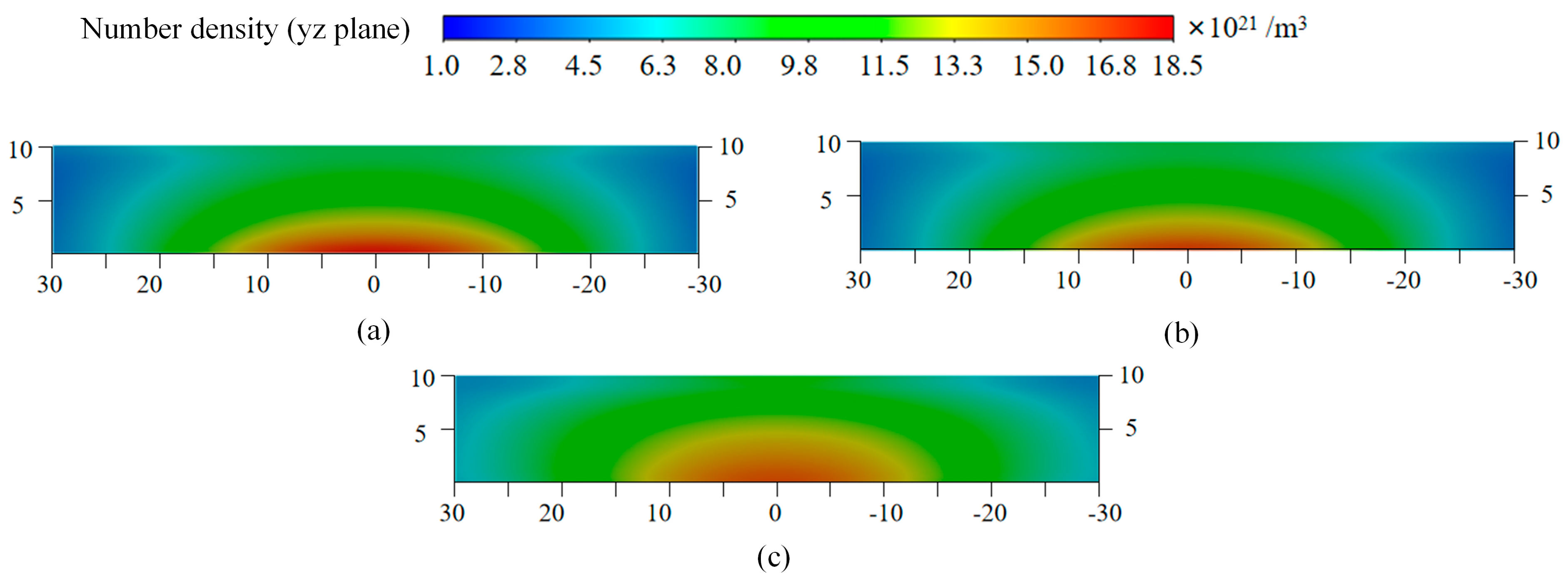
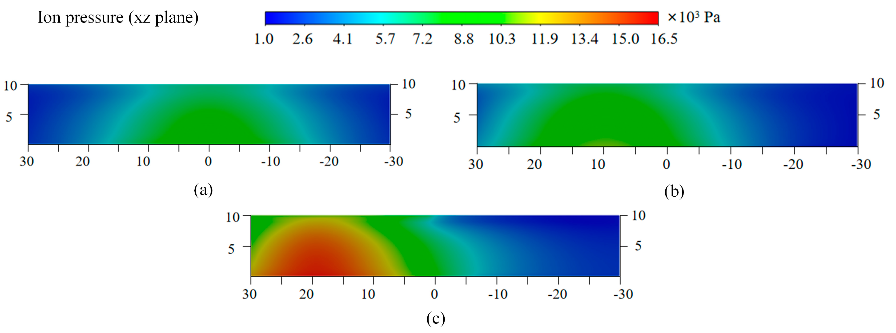
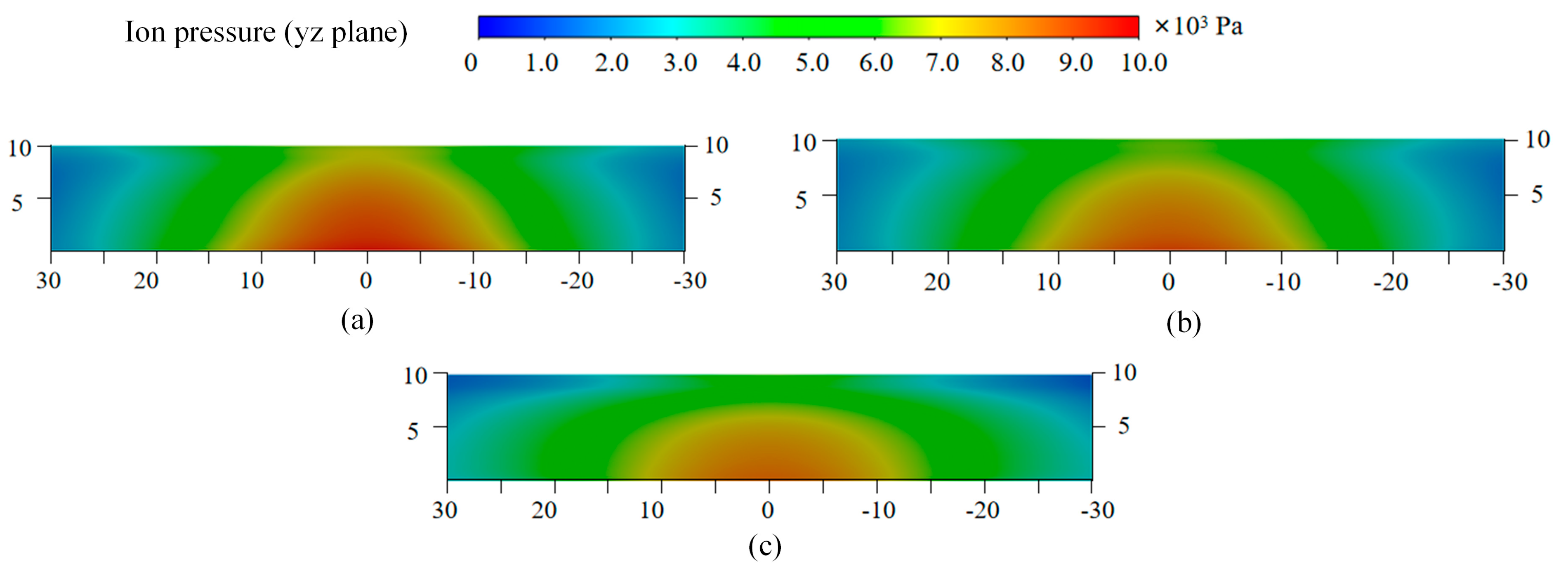
Table 1 shows the comparison of arc parameters at the corresponding coordinates. For the comparison between ion pressure and ion number density, we chose the cathode side. For 33% arc offset, the ion pressure and density at the arc root reach 10,900 Pa and 20.4 × 10²¹ m−3, respectively, while at the mirrored coordinate, these values decrease to 5200 Pa and 9.7 × 10²¹ m−3, representing approximately 50% of the arc root values. For 67% offset, the arc root registers 16,300 Pa and 29.4 × 10²¹ m−3, whereas the mirrored point exhibits a sharp decline to 2700 Pa and 5.5 × 10²¹ m−3, corresponding to less than 20% of the arc root parameters.
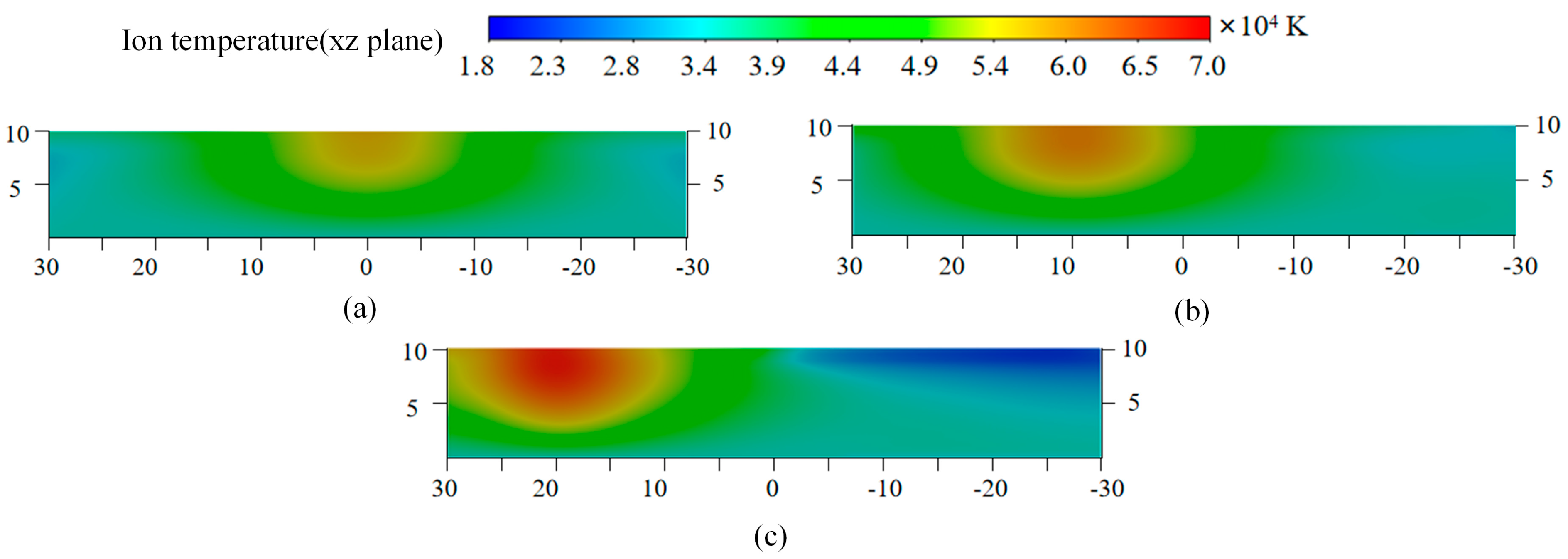
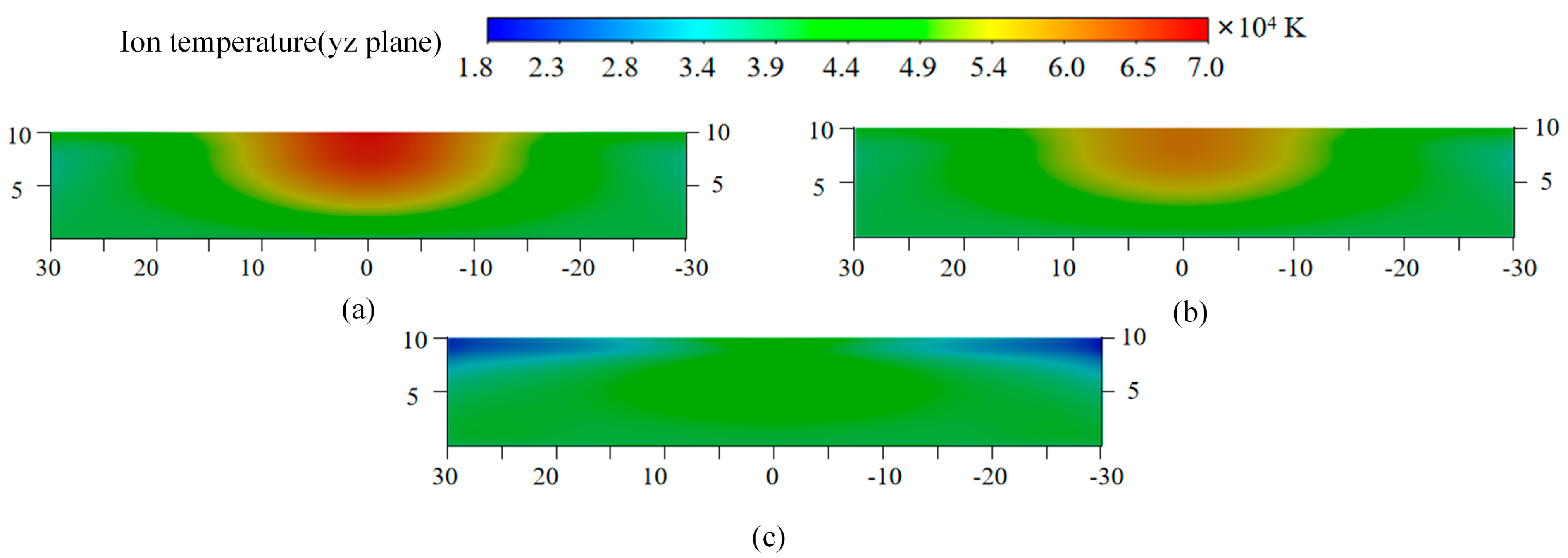
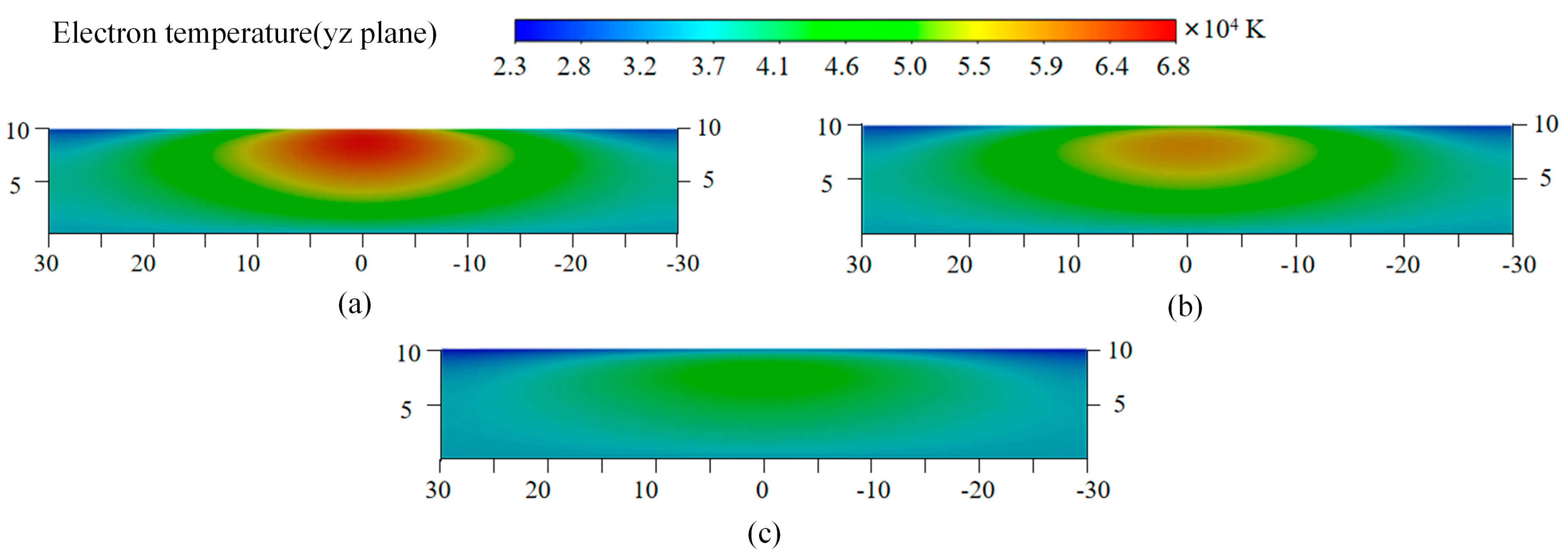
For ion temperature and electron temperature on the anode side, comparative analysis reveals significant thermal asymmetry at mirrored coordinates. Under 33% arc offset, Ti reaches 60,800 K and Te reaches 72,500 K at the arc root, while the corresponding negative semi-axis point exhibits reductions of exactly 32% in Ti and 55% in Te. At 67% arc offset, Ti reaches 69,000 K and Te reaches 80,100 K at the arc root, with more pronounced reductions of 67% in Ti and 71% in Te at the mirrored point.
Arc offset induces not only spatial heterogeneity in vacuum arc but also significant parameter amplification. As quantified in Table 2, during 33% slight arc offset, the peak values of ion pressure, ion density, ion temperature, electron temperature, and current density increase by 12%, 11%, 6%, 6%, and 14%, respectively, relative to symmetric arc condition. Under 67% severe offset, the maximum increase in these five parameters is significantly higher, reaching 67%, 61%, 12%, 18%, and 47%.
Asymmetric arc ablation induces significant plasma morphology changes, intensifying energy deposition into the anode and accelerating contact erosion due to elevated plasma parameters. Under 33% minor offset, peak parameter increases remain moderate with 6–14% versus symmetric arcing, with erosion effects within controllable bounds. During 67% severe offset, critical parameter escalation occurs with 12–67% amplification compounded by extreme spatial heterogeneity, which significantly impedes interruption capability through uncontrolled anode erosion and material expulsion.
In high-current vacuum arcs, the arc delivers a large amount of energy to the anode. When the energy is high enough, the anode material is eroded, and the anode surface is damaged, which can easily lead to discharge after zero crossing. At the same time, the metal vapor released by the high-temperature anode damages the insulation strength of the vacuum gap, thereby reducing the success rate of disconnection.
The heat flux density transferred to the anode increases with elevated arc density and temperature. Table 1 and Table 2 demonstrate that under asymmetric arcing conditions, the arc undergoes intensified constriction, thereby augmenting localized heat flux density toward the anode. This phenomenon exacerbates severely at 66% severe offset condition. Furthermore, when the anode arc root deviates from the contact center, radial heat dissipation efficiency decreases substantially. Consequently, asymmetric arcing induces significantly enhanced anode erosion compared to symmetric counterparts.
Therefore, in practical vacuum interrupters, enhanced manufacturing precision and improved operating mechanism performance are required to minimize severe asymmetric arcing condition.

5. Conclusions

Asymmetric arcing in vacuum arcs significantly alters plasma distributions. This article establishes a magnetohydrodynamic model to quantitatively analyze it. The investigated contacts feature a 60 mm diameter, with cases analyzed for symmetric arcing, 33% minor arc offset (arc root displacement: 10 mm), and 67% severe arc offset (arc root displacement: 20 mm). Key findings are summarized below:
1. Arc offset induces plasma distribution heterogeneity. Parameters at the arc root on the positive semi-axis were compared with mirrored coordinates on the negative semi-axis. For 33% offset, ion pressure and density at the negative coordinate approximate 50% of root values. Under 67% offset, these parameters fall below 20%. Simultaneously, for the 33% arc offset situation, the ion temperature and electrons at the corresponding coordinate points decreased by 30–50%, while for the 67% arc offset situation, they decreased by 70%.
2. Severe arc offset produces pronounced escalation of peak plasma parameters. Under 33% offset, maximum values of ion pressure, ion density, ion temperature, electron temperature, and current density increase by 12%, 11%, 6%, 6%, and 14%, respectively, relative to symmetric arcing. At 67% severe arc deviation, the maximum increases in these five parameters demonstrate stronger amplification, reaching 67%, 61%, 12%, 18%, and 47%.

Author Contributions

Investigation, Y.B., Q.G., and C.C.; Validation, C.W.; Writing—original draft, Z.Z. All authors have read and agreed to the published version of the manuscript.

Funding

This research was funded by Key Research and Development Plan of Shaanxi Province, grant number 2025CY-YBXM-134.

Data Availability Statement

The raw data supporting the conclusions of this article will be made available by the authors on request.

Conflicts of Interest

The authors declare no conflicts of interest.

Abbreviations

The following abbreviations are used in this manuscript:
niIon number density
uiIon velocity
neElectron number density
ziIonization state
miIon weight
piIon pressure
peElectron pressure
ueElectron velocity
BMagnetic field
Fie FeiFriction force between ions and electrons
jCurrent density
σConductivity
Qei QieEnergy transferred between ions and electrons
qeElectron heat flux
qiIon heat flux
λeElectron thermal conductivity
λiIon thermal conductivity
kBoltzmann constant
φshAnode sheath voltage

References

  1. Liu, Z.; Wang, J.; Geng, Y.; Wang, Z. Switching Arc Phenomena in Transmission Voltage Level Vacuum Circuit Breakers [M/OL]; Springer: Singapore, 2021. [Google Scholar]
  2. Węgierek, P.; Kostyła, D.; Lech, M. Directions of Development of Diagnostic Methods of Vacuum Medium-Voltage Switchgear. Energies 2023, 16, 2087. [Google Scholar] [CrossRef]
  3. Slade, P.G. The Application of Vacuum Interrupters in HVDC Circuit Breakers. IEEE Trans. Plasma Sci. 2022, 50, 4675–4682. [Google Scholar] [CrossRef]
  4. Miller, H.C. Vacuum Arcs. IEEE Trans. Plasma Sci. 2023, 51, 1585–1594. [Google Scholar] [CrossRef]
  5. Anders, A. Glows, arcs, ohmic discharges: An electrode-centered review on discharge modes and the transitions between them. Appl. Phys. Rev. 2024, 11, 031310. [Google Scholar] [CrossRef]
  6. Du, S.; Cheng, X.; Ge, G.; Chen, H.; Guo, L. Study on insulation configurations of environment-friendly tank multi-break vacuum circuit breakers. Vacuum 2025, 233, 114011. [Google Scholar] [CrossRef]
  7. Gortschakow, S.; Franke, S.; Methling, R.; Gonzalez, D.; Lawall, A.; Taylor, E.D.; Graskowski, F. Properties of Vacuum Arcs Generated by Switching RMF Contacts at Different Ignition Positions. Energies 2020, 13, 5596. [Google Scholar] [CrossRef]
  8. Jiang, Y.; Ma, S.; Li, Q.; Wang, W.; Zhang, K.; Cao, R.; Wu, J. Non-uniform pinching of short-gap intermediate frequency vacuum arc without controlled magnetic field. Vacuum 2024, 227, 113394. [Google Scholar] [CrossRef]
  9. Liu, L.; Liu, S.; Yuan, Z.; Chen, L.; Wang, J.; Wang, Z.; Ding, C. Research on the influence of grain size of CuCr contact on the characteristics of cathode spot and cathode surface erosion in vacuum arc. Vacuum 2024, 219, 112767. [Google Scholar] [CrossRef]
  10. Shkol’nik, S.M. Processes on Contacts and Thermal State of Contact Surfaces in AMF-Contact Systems of Medium-Voltage Vacuum Interrupters when Switching the Limiting Current: A Review. IEEE Trans. Plasma Sci. 2022, 50, 2634–2641. [Google Scholar] [CrossRef]
  11. Dorraki, N.; Methling, R.; Gortschakow, S. Advanced temporal analysis of anode activity during mode transitions in high current vacuum arcs. J. Phys. D Appl. Phys. 2025, 58, 075204. [Google Scholar] [CrossRef]
  12. Li, Y.; Yuan, Z.; Liu, S.; Chen, L.; Wu, C.; Ya, P. Emission Spectroscopic Diagnosis of 2-D Particle Distribution in Vacuum Arcs Under Different Currents. IEEE Trans. Plasma Sci. 2024, 52, 2837–2845. [Google Scholar] [CrossRef]
  13. Yan, W.; Wang, Z.; Cao, Z.; Li, H.; Sun, L.; Wang, J. Particle Generation, Their Behavior and Effect on Post-Arc Breakdowns After Capacitive-Current Vacuum Arc Interruption. IEEE Trans. Power Deliv. 2022, 37, 4303–4314. [Google Scholar] [CrossRef]
  14. Saifutdinov, A.I. Numerical study of various scenarios for the formation of atmospheric pressure DC discharge characteristics in argon: From glow to arc discharge. Plasma Sources Sci. Technol. 2022, 31, 094008. [Google Scholar] [CrossRef]
  15. Baeva, M.; Uhrlandt, D. Characterization and applications of direct current microarcs: A review. J. Phys. D Appl. Phys. 2025, 58, 263001. [Google Scholar] [CrossRef]
  16. Benilov, M.S.; Almeida, N.A.; Baeva, M.; Cunha, M.D.; Benilova, L.G.; Uhrlandt, D. Account of near-cathode sheath in numerical models of high-pressure arc discharges. J. Phys. D Appl. Phys. 2016, 49, 215201. [Google Scholar] [CrossRef]
  17. Schade, E.; Shmelev, D.L. Numerical simulation of high-current vacuum arcs with an external axial magnetic field. IEEE Trans. Plasma Sci. 2003, 31, 890–901. [Google Scholar] [CrossRef]
  18. Huang, X.; Zhao, S.; Xu, H.; Song, J.; Su, H.; Ning, W.; Zhao, L.; Jia, S. Numerical Study of Large Contact Diameter and Gap High Current Vacuum Arc. IEEE Trans. Plasma Sci. 2024, 52, 4428–4438. [Google Scholar] [CrossRef]
  19. Hashemi, E.; Niayesh, K. DC Current Interruption Based on Vacuum Arc Impacted by Ultra-Fast Transverse Magnetic Field. Energies 2020, 13, 4644. [Google Scholar] [CrossRef]
  20. Zhang, Z.; Liu, Z.; Ma, H.; Wang, C.; Kong, G.; Geng, Y.; Wang, J. Anode Input Heat Flux Density in High-Current Vacuum Arcs as Anode Spot Formation. IEEE Trans. Plasma Sci. 2022, 50, 3732–3741. [Google Scholar] [CrossRef]
  21. Zhang, Z.; Ma, H.; Liu, Z.; Geng, Y.; Wang, J. Cathode-constriction and column-constriction in high current vacuum arcs subjected to an axial magnetic field. J. Phys. D Appl. Phys. 2018, 51, 145203. [Google Scholar] [CrossRef]
  22. Yang, Z.; Lu, W.; Cai, D.; Huang, Q.; Xing, Y.; Wang, L. Numerical investigation on the interaction between droplets and vacuum arc plasma considering ablation cloud. Phys. Scr. 2025, 100, 045610. [Google Scholar] [CrossRef]
  23. Song, M.; Liu, Z.; Dong, Y.; Sun, Q.; Wang, Z.; Zhang, H.; Wu, W.; Yang, W.; Zhou, Q. Study on the mechanisms of anode plasma generation and ion acceleration in low-current pulsed vacuum arc discharge. Phys. Plasmas 2025, 32, 023506. [Google Scholar] [CrossRef]
  24. Wang, L.; Wang, X.; Chen, J.; Luo, M.; Xie, Y.; Wang, H. Numerical simulation of CuCr alloys vacuum arc under conditions of arc contraction, deflection, and anode vapor. Phys. Plasmas 2024, 31, 123501. [Google Scholar] [CrossRef]
  25. Xie, Y.; Wang, L.; Chen, J.; Wang, X. Three-dimensional transient modeling and simulation of high-current multi-component vacuum arc under transverse magnetic field. J. Appl. Phys. 2024, 136, 113301. [Google Scholar] [CrossRef]
  26. Ye, J.; Yang, P.; Yuan, Z.; Liu, L.; Chen, L.; Pan, Y. 3D simulation of the interaction between double copper cathode spot jets in vacuum arc. AIP Adv. 2024, 14, 095318. [Google Scholar] [CrossRef]
  27. Wei, L.; Xiu, S.; Liu, Z.; Guo, M.; Zhu, D. Numerical Simulation and Experimental Investigation of the Influence of Gap Distance on Vacuum Arc Characteristics Between TMF Contacts. IEEE Trans. Plasma Sci. 2024, 52, 951–958. [Google Scholar] [CrossRef]
Figure 1. The ion density distribution on the xz−plane: (a) symmetric arcing condition; (b) 33% arc center offset; (c) 67% arc center offset.
Energies 18 04025 g001
Figure 2. The ion density distribution on the yz−plane: (a) symmetric arcing condition; (b) 33% arc center offset; (c) 67% arc center offset.
Energies 18 04025 g002
Figure 3. The ion pressure distribution on the xz−plane: (a) symmetric arcing condition; (b) 33% arc center offset; (c) 67% arc center offset.
Energies 18 04025 g003
Figure 4. The ion pressure distribution on the yz−plane: (a) symmetric arcing condition; (b) 33% arc center offset; (c) 67% arc center offset.
Energies 18 04025 g004
Figure 5. The ion temperature distribution on the xz-plane: (a) symmetric arcing condition; (b) 33% arc center offset; (c) 67% arc center offset.
Energies 18 04025 g005
Figure 6. The ion temperature distribution on the yz-plane: (a) symmetric arcing condition; (b) 33% arc center offset; (c) 67% arc center offset.
Energies 18 04025 g006
Figure 7. The electron temperature distribution on the xz-plane: (a) symmetric arcing condition; (b) 33% arc center offset; (c) 67% arc center offset.
Energies 18 04025 g007
Figure 8. The electron temperature distribution on the yz-plane: (a) symmetric arcing condition; (b) 33% arc center offset; (c) 67% arc center offset.
Energies 18 04025 g008
Figure 9. Axial current density distribution along the x-axis: (a) cathode surface; (b) middle plane of the arc column; (c) anode surface.
Energies 18 04025 g009aEnergies 18 04025 g009b
Table 1. The comparison of the arc parameters between the arc root and the corresponding mirrored coordinate.
Arc Condition33% Arc Offset67% Arc Offset
x-coordinate0.01−0.01Decrease rate0.02−0.02Decrease rate
Ion pressure/Pa10,900520052%16,300270083%
Ion number density/1021 m−320.49.752%29.45.581%
Ion temperature/K60,80041,20032%69,00022,90067%
Electron temperature/K72,50032,90055%80,10023,10071%
Table 2. The arc parameters under three different arc states (marked with the improvement of parameters under arc offset state). ↑ symbol indicates the increase rate relative to baseline value.
Arc ConditionSymmetrical Arc33% Arc Offset67% Arc Offset
Arc root coordinate(0, 0, 0)(0.01, 0, 0)(0.02, 0, 0)
Max ion pressure/Pa975010,900↑12%16,300↑67%
Max ion number density/1021 m−318.320.4↑11%29.4↑61%
Max ion temperature/K57,50060,800↑6%69,000↑12%
Max electron temperature/K67,70072,500↑6%80,100↑18%
Max current density/106 A·m−222.125.2↑14%32.4↑47%
Disclaimer/Publisher’s Note: The statements, opinions and data contained in all publications are solely those of the individual author(s) and contributor(s) and not of MDPI and/or the editor(s). MDPI and/or the editor(s) disclaim responsibility for any injury to people or property resulting from any ideas, methods, instructions or products referred to in the content.

