
Design Optimization of Valve Assemblies in Downhole Rod Pumps to Enhance Operational Reliability in Oil Production

 , ,
, ,  and
and 
Abstract
1. Introduction
- To collect and analyze statistical data on the failure modes of DRPUs operating in actual field conditions, with a focus on valve-related issues;
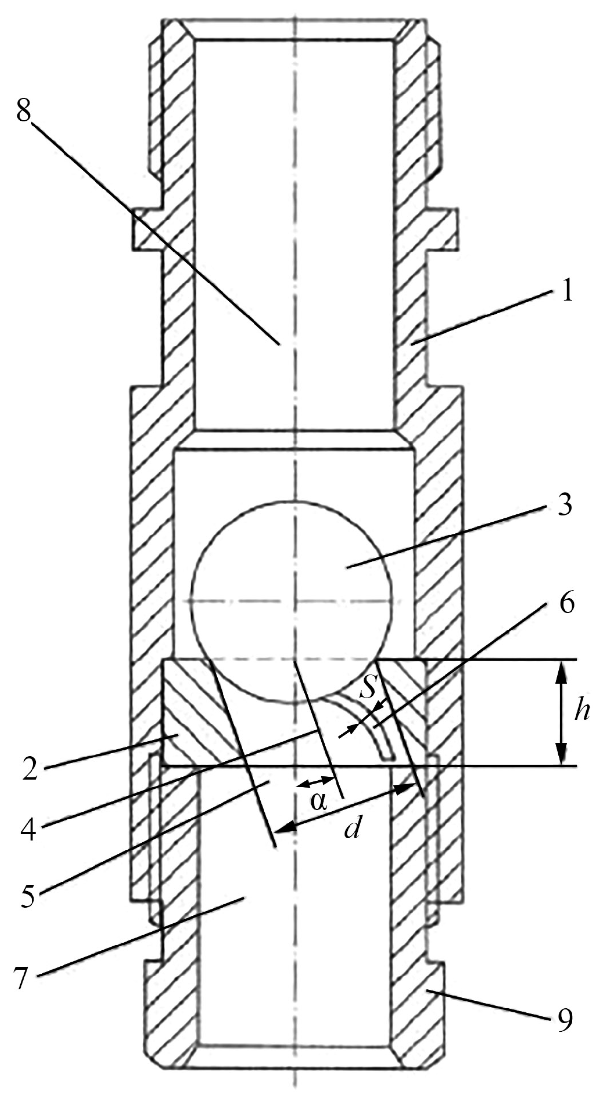
- To develop a modified valve assembly design incorporating a flow turbulizer intended to reduce localized wear and to improve sealing performance;
- To perform the laboratory testing of the proposed valve design under simulated downhole conditions in order to evaluate its mechanical behaviour and functional efficiency;
- To conduct pilot field trials of the redesigned valves in real oil wells and to assess their durability and performance in comparison with standard designs.
2. Methods and Materials
2.1. Collection of Oilfield Equipment Failure Statistics
2.2. Design of the DRPU Structure and Manufacture of DRPU Elements
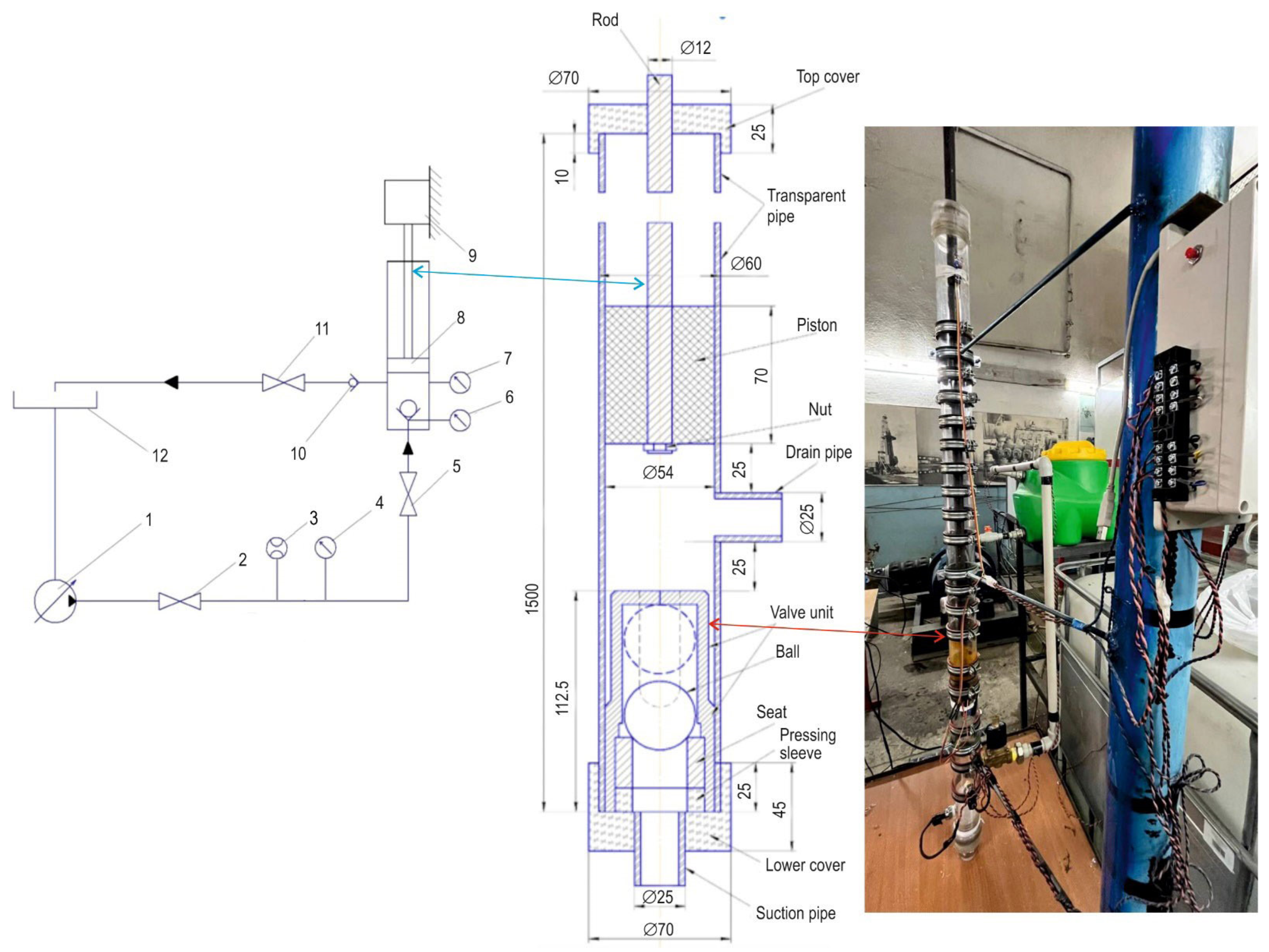
2.3. Laboratory Tests of the Developed DRPU
2.4. Industrial Testing of the Developed DRPU
3. Results and Discussion
3.1. Analysis of Failure Statistics and Refinement of the DRP Valve Assembly Design
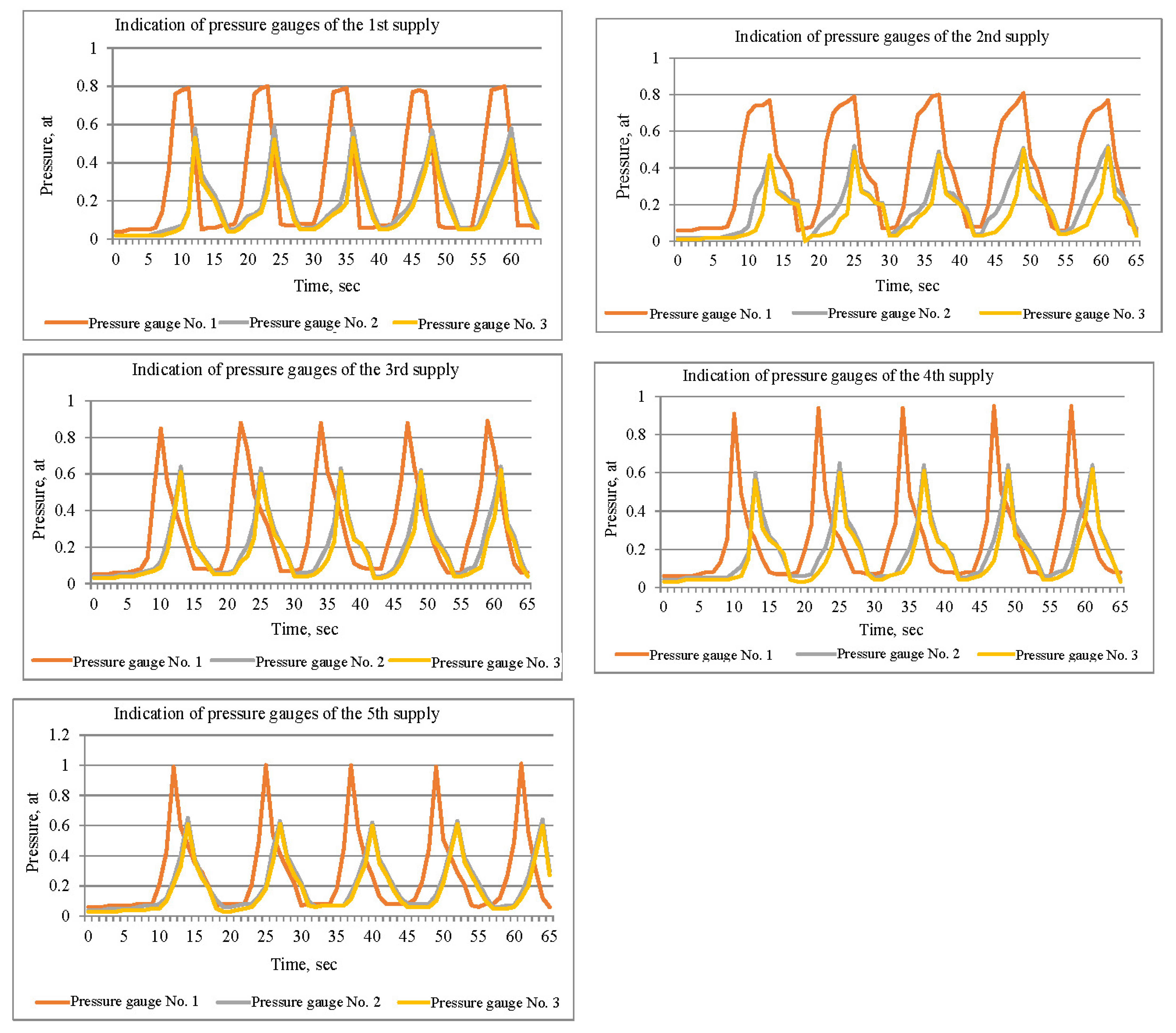
3.2. Conducting Bench Experimental Tests
3.3. Conducting Pilot Field Tests
4. Discussion
5. Conclusions
Author Contributions
Funding
Institutional Review Board Statement
Informed Consent Statement
Data Availability Statement
Conflicts of Interest
References
- Exactitude Consultancy. Oil & Gas Pumps Market (2019–2028); Forecast to Reach USD 10.80 Billion by 2028 at CAGR 6.4%; Global Report; GlobeNewswire: Luton, UK, 2022. [Google Scholar]
- Extractive Industries Transparency Initiative. Kazakhstan Country Facts. EITI. 2022. Available online: https://eiti.org/countries/kazakhstan (accessed on 1 July 2025).
- Jurasz, J.; Canalesc, F.A.; Kiesd, A.; Guezgouz, M.; Beluco, A. A review on the complementarity of renewable energy sources: Concept, metrics, application and future research directions. Sol. Energy 2020, 195, 703–724. [Google Scholar] [CrossRef]
- A.T. Consulting. Market Overview of Submersible Pumps for Oil Production in Russia. 2023. Available online: https://atconsult.ru/oilpump.html (accessed on 1 March 2025).
- Bakhtizin, R.N.; Urazakov, K.R.; Topolnikov, A.S.; Azizov, A.M.; Komkov, A.G.; Ishmukhametov, B.H. Oil Production by Rod Installations in Complicated Conditions; UGNTU Publishing House: Ufa, Russian, 2016. [Google Scholar]
- Stosiak, M.; Lubecki, M.; Karpenko, M. Designing a Composite Hydraulic Cylinder Using Genetic Algorithms. Actuators 2025, 14, 77. [Google Scholar] [CrossRef]
- Molchanov, A.V. Stankov-kachalki: Problems and Prospects of Improvement. Promyshlennye Vedom. 2007, 10, 46–50. [Google Scholar]
- Adonin, A.N. Oil Extraction by Rod Pumps; Nedra: Moscow, Russian, 1979. [Google Scholar]
- Andrew, S.P.; Eiselstein, L.E.; Caligiuri, R.D.; Kim Parnell, T. Evaluation of a failure in a chlorine production facility. In Proceedings of the ASME International Mechanical Engineering Congress and Exposition, New York, NY, USA, 11–16 November 2001; Volume 2, pp. 771–781. [Google Scholar]
- Belogolov, Y.I.; Pogodin, V.K.; Gozbenko, V.E.; Kargapoltsev, S.K.; Olentsevich, V.A.; Gladkih, A.M. Method for determining the sealing forces in a shut-off valve. IOP Conf. Ser. Mater. Sci. Eng. 2021, 1064, 012036. [Google Scholar] [CrossRef]
- Elagina, O.Y.; Buklakov, A.G.; Dubinov, Y.S.; Dedok, D.V. Gas-abrasive wear of shut-off valves and process piping of compressor and gas distribution stations. Mater. Phys. Mech. 2023, 51, 84–92. [Google Scholar] [CrossRef]
- Syrkin, V.V.; Balakin, P.D.; Treyer, V.A. Study on hydraulic direct-acting relief valve. J. Phys. Conf. Ser. 2017, 858, 012035. [Google Scholar] [CrossRef]
- Bartenev, D.A.; Boiko, A.Y.; Matyushin, E.G.; Regush, L.A.; Fedorov, O.I.; Grebkov, A.A. Prestressed polymeric sealing elements of pipeline shut-off valves. Chem. Pet. Eng. 1986, 22, 265–267. [Google Scholar] [CrossRef]
- Alekhnovich, V.; Syasko, V.; Umanskii, A. Multi-Parameter Complex Control of Metal Coatings on Ball Plugs of Pipeline Shut-Off Valves. Inventions 2024, 9, 78. [Google Scholar] [CrossRef]
- Alexandrov, I.A.; Muranov, A.N.; Mikhailov, M.S. Development of an Algorithm for Automated Evaluation of the Operability of Structural Elements of Shut-off Valves. In Proceedings of the 2021 IEEE International Conference “Quality Management, Transport and Information Security, Information Technologies” T and QM and IS 2021, Yaroslavl, Russian, 6–10 September 2021; pp. 257–261. [Google Scholar] [CrossRef]
- Arbuzov, N.S. Protection of the marine oil terminal against hydraulic shock using the fast shut-off valve. Neft. Khozyaystvo—Oil Ind. 2012, 2, 106–108. [Google Scholar]
- Soboleva, J.; Kerimov, A.; Lampezhev, A. Consideration of Temperature Factors when Designing Butterfly Check Valves for Hazardous Production Facilities. Civ. Eng. J. 2023, 9, 263–274. [Google Scholar] [CrossRef]
- Hu, C.-S.; Qin, H.; Zhu, J.; Zhao, Z.-X. Analysis of the causes of valve stem nut fracture in shut-off valves. Dongbei Daxue Xuebao/J. Northeast. Univ. 2012, 33 (Suppl. 2), 76–78. [Google Scholar]
- Chinyaev, I.R.; Fominykh, A.V.; Tel’minov, A.V. Gate Valve with Internal Bypass; Lecture Notes in Mechanical Engineering; Springer: Cham, Switzerland, 2022; pp. 746–751. [Google Scholar] [CrossRef]
- Hasanov, I.I.; Guliyev, A.A. Development of effective sealing units for oil and gas equipment in the oil and gas production system [Opracowanie skutecznych zespołów uszczelniających dla urządzeń naftowych w systemie wydobywczym ropy i gazu]. Nafta—Gaz 2023, 79, 464–472. [Google Scholar] [CrossRef]
- Gan, X.; Akin, J.E. Low-cycle fatigue life estimation of a subsurface safety valve. In Proceedings of the Materials Science and Technology Conference and Exhibition 2010, MS and T’10, Houston, TX, USA, 17–21 October 2010; Volume 2, pp. 1486–1494. [Google Scholar]
- Vasin, S.A.; Plakhotnikova, E.V. Electric drive setting torque calculation method in electric drive shut-off valve system with rectilinea displacement of the valve closure. J. Min. Inst. 2018, 232, 407–412. [Google Scholar] [CrossRef]
- Turbygin, V.; Klabukov, A.G.; Cheshlya, R.R.; Vikulin, Y.A. Wear resistance of metal-rubber sealing pairs in shut-off and regulating valves. Sov. Eng. Res. 1991, 11, 42–45. [Google Scholar]
- Zhukov, D.V.; Melnikov, A.A.; Konovalov, S.V.; Afanasyev, A.V. Analysis of manufacturing internal pressure induced defects of the pipe wall with modeling of stresses. Chernye Met. 2021, 10, 49–55. [Google Scholar] [CrossRef]
- Pogodin, V.K.; Belogolov, Y.I.; Gozbenko, V.E.; Kargapoltsev, S.K.; Olentsevich, V.A.; Gladkih, A.M. Calculation of sealing pressures of shut-off valves. IOP Conf. Ser. Mater. Sci. Eng. 2021, 1064, 012035. [Google Scholar] [CrossRef]
- Soboleva, J.A.; Kerimov, A.M.; Anudinov, S.S.; Kocharov, M.A. Operation Simulation for a Check Valve Used in High-Performance Systems. Civ. Eng. J. 2023, 9, 3202–3217. [Google Scholar] [CrossRef]
- Ivanov, V.V.; Oleinikov, A.V.; Denisevich, D.S.; Pektimirov, B.G. Emergency Shut-Off Valve for Pipelines. Chem. Pet. Eng. 2013, 49, 400–402. [Google Scholar] [CrossRef]
- Afinogentov, A.A.; Ivanova, N.I.; Fedotova, I.A. The Method of Shut-off Valves Optimal Placing on Trunk Oil Pipeline. IOP Conf. Ser. Earth Environ. Sci. 2019, 272, 022038. [Google Scholar] [CrossRef]
- Kislyakov, Y.P. Strategy for further development of the Uzen oil and gas field. In Collection of Proceedings Geology, Development, Drilling, Oil and Gas Production, Ecology, Training and Professional Development; JSC ‘NIPIneftegaz’: Ufa, Russian, 2014; Volume 1. [Google Scholar]
- Nurshakhanova, L.K. Analysis of Methods of Impact and Assessment of Changes in Oil Properties in the Process of Development of the Uzen Field. Ph.D. Thesis, Gubkin Russian State University, Moscow, Russian, 2005. [Google Scholar]
- Shinyakov, Y.; Sukhorukov, M.; Torgaeva, D.; Soldatov, A. Methods and Facilities for Monitoring the Operation of a Sucker Rod Pump. Int. J. Mech. Eng. Technol. 2018, 9, 1224–1231. Available online: https://iaeme.com/MasterAdmin/Journal_uploads/IJMET/VOLUME_9_ISSUE_12/IJMET_09_12_124.pdf (accessed on 1 July 2025).
- Fakher-Sefat, S.; Khlaifat, A.; Hossain, M.E.; Nameer, H. A Comprehensive Review of Sucker Rod Pumps’ Components, Diagnostics, Mathematical Models, and Common Failures and Mitigations. J. Pet. Explor. Prod. Technol. 2021, 11, 3815–3839. [Google Scholar] [CrossRef]
- Togasheva, A. Well Operation by Plunger Rod Pumps in Difficult Conditions: A Case Study of the Uzen Field. Nauk. Visnyk Natsionalnoho Hirnychoho Universytetu 2025, 1, 22–30. [Google Scholar] [CrossRef]
- Strekalovskaya, D.A.; Davydov, A.D.; Lyashenko, D.V.; Tleshev, M. Failure Analysis of Plunger Rod and Barrel of Sucker Rod Pumps. Int. J. Mech. Prod. Eng. Res. Dev. 2020, 10, 14835–14844. [Google Scholar] [CrossRef]
- Dolov, T.R. Research of Work of Valve Units of Downhole Rod Pumping Units. Ph.D. Thesis, Gubkin Russian State University, Moscow, Russian, 2017. [Google Scholar]
- Alper, R. Ball and Seat-Type Check Valve for Down-Hole Rod Pump. U.S. Patent 5,297,579 A, 22 March 1994. [Google Scholar]
- Khaliullin, F.H. Valve of a Downhole Rod Pump. RU Patent RU2059885C1 MPK F04B 47/02, 10 May 1996. [Google Scholar]
- Basos, G.Y.; Valovskiy, K.V. Suction Valve of a Depth Pump. RU Patent RU2487271C1 MPC F04B 53/10, 10 July 2013. [Google Scholar]
- Wang, Y.; Chen, C.; Ren, R.; Xue, Z.; Wang, H.; Zhang, Y.; Wang, J.; Wang, J.; Chen, L.; Mu, W. Ferrite Formation and Decomposition in 316H Austenitic Stainless Steel Electro Slag Remelting Ingot for Nuclear Power Applications. Mater. Charact. 2024, 218, 114581. [Google Scholar] [CrossRef]
- Ivey, R.K. Sucker Rod Pump with Improved Ball and Seat. U.S. Patent 8061381B2, 22 November 2011. Available online: https://patents.google.com/patent/US8061381B2 (accessed on 18 July 2025).
- Zaurbekov, S.A.; Zaurbekov, K.S.; Balgaev, D.E.; Kadyrov, J.N. Ball Valve of Deep-Seated Pump. RK Patent No. 34,582, bulletin No. 37, 18 September 2020. [Google Scholar]
- Wang, Y.; Chen, C.; Yang, X.Y. Solidification modes and delta-ferrite of two types of 316L stainless steels: A combination of as-cast microstructure and HT-CLSM research. J. Iron Steel Res. Int. 2025, 32, 426–436. [Google Scholar] [CrossRef]
- Chen, L.; Wang, Y.; Li, Y.; Zhang, Z.; Xue, Z.; Ban, X.; Hu, C.; Li, H.; Tian, J.; Mu, W.; et al. Effect of Nickel Content and Cooling Rate on the Microstructure of as Cast 316 Stainless Steels. Crystals 2025, 15, 168. [Google Scholar] [CrossRef]
- Fakher, S.; Khlaifat, A.; Hossain, M.E.; Nameer, H. Rigorous Review of Electrical Submersible Pump Failure Mechanisms and Their Mitigation Measures. J. Pet. Explor. Prod. Technol. 2021, 11, 3799–3814. [Google Scholar] [CrossRef]
- Fakher, S.; Khlaifat, A.; Hossain, M.E.; Nameer, H. Improving Electric Submersible Pump Efficiency and Mean Time Between Failure Using Permanent Magnet Motor. Upstream Oil Gas Technol. 2022, 9, 100074. [Google Scholar] [CrossRef]
- Peroutka, J. Sucker Rod Pump Standing Valve Movement Dynamics Investigation. Master’s Thesis, Montanuniversität Leoben, Leoben, Austria, 2022. [Google Scholar]
- Palka, M.; Czyż, A. Frequency-Elastic Control for Sucker-Rod Pumping Systems: Reducing Impulse Load and Increasing Efficiency. Energy Technol. 2021, 9, 1050–1060. [Google Scholar]
- Cheng, H.; Yu, H.; Zeng, P.; Osipov, E.; Li, S.; Vyatkin, V. Automatic Recognition of Sucker-Rod Pumping System Working Conditions Using Dynamometer Cards with Transfer Learning and SVM. Sensors 2020, 20, 5659. [Google Scholar] [CrossRef] [PubMed]
- Zhao, W.; Zhou, B.; Wang, Y.; Liu, W. Semi-Supervised Class-Incremental Sucker-Rod Pumping Well Operating Condition Recognition Based on Multi-Source Data Distillation. Sensors 2025, 25, 2372. [Google Scholar] [CrossRef] [PubMed]
- Fan, Z.; Song, X.; Wang, D.; Ayasrah, M.; Li, S. Poroelastic Solutions of a Semipermeable Borehole under Nonhydrostatic In Situ Stresses within Transversely Isotropic Media. Int. J. Geomech. 2025, 25, 04024342. [Google Scholar] [CrossRef]


| Production and Service Enterprise | Number of Well Repairs | Gradation by Causes of Field Equipment Failure | ||||||||
|---|---|---|---|---|---|---|---|---|---|---|
| Mechanical Impurities Paraffin-Salting Salt-Salting Pump Valve Leakage Leakage of Pump Valves Oil Leaks | Paraffin-Salting | Salt-Salting | Leakage of Pump Valves | Oil Leaks | Tubing Leakage | Rods Breakage | Slag, Scale in Gasoil Equipment | Accident with Field Equipment | ||
| Oil and Gas Production Division-2 | 2764 | 596 | 118 | 10 | 388 | 487 | 810 | 240 | 0 | 14 |
| No. | Characteristics | Units of Measurement | Al-Si-Mg Aluminum Alloy D16T (Hardened and Aged) |
|---|---|---|---|
| 1 | Yield strength (min) | MPa | 180 |
| 2 | Tensile strength (min) | MPa | 300 |
| 3 | Hardness (max) | НВ | 105 |
| 4 | Fatigue strength (min) | N/mm2 | 100 |
| 5 | Relative elongation (min) | % | 8–10 |
| 6 | Density | g/cm3 | 2.8 |
| 7 | Heat capacity | J/kg K | 922 |
| Data on Discharged Pumps | |||||
|---|---|---|---|---|---|
| Date of running | 28 July 23 | 14 August 23 | 15 August 23 | 17 August 23 | 17 August 23 |
| Well number | No. 6356 | No. 4702 | No. 8509 | No. 2093 | No. 3093 |
| Pump number | 302,036 | 303,169 | 303,149 | 308,086/11 | 307,932/10 |
| Well data | |||||
| Well type | Vertical | Vertical | Vertical | Vertical | Vertical |
| Field | Uzen | Uzen | Uzen | Uzen | Uzen |
| Horizon number | 15 | 15 | 13 | 17 | 14 |
| Well purpose | Oil | Oil | Oil | Oil | Oil |
| Commissioning date | 30 June 2014 | 31 July 2012 | 24 April 1993 | 21 September 1974 | 25 May 1979 |
| Diameter of production casing/completed production casing, mm | 168 | 168 | 146 | 168/114 | 168 |
| Pump running depth, m | 696 | 680 | 912 | 400 | 640 |
| Stroke length, m | 3.0 | 3.0 | 3.0 | 3.0 | 3.5 |
| Number of swings, rpm | 4.93 | 6.15 | 6.2 | 6.15 | 6.2 |
| Pump diameter, mm | 70 | 70 | 70 | 70 | 70 |
| Dynamic level | 138 | 420 | 415 | 326 | 113 |
| Static level | 0 | 44 | 265 | 0 | 237 |
| Rpl | 113.7 | 122.1 | 128 | 108 | 100.7 |
| Rzab | 106.2 | 91.4 | 71.9 | 120.2 | 101.9 |
| Actual bottom hole, m | 1215 | 1324 | 1170 | 950 | 1116 |
| Depth of tubing, run | 696 | 680 | 912 | 400 | 640 |
| Liquid flow rate, m3/day, (mode/actual) | 70.0/33.0 | 70.0/64.0 | 40.0/42.0 | 85.0/74.0 | 60.0/62.0 |
| Water cut, % (mode/fact) | 90.0/95.4 | 90.0/95.0 | 90.0/96.0 | 95.0/97.9 | 95.0/98.3 |
| Oil flow rate, tonnes per day (mode/fact) | 5.88/1.27 | 5.8/1.35 | 3.4/1.32 | 3.57/1.29 | 2.52/0.88 |
| Data on Discharged Pumps | ||||||
|---|---|---|---|---|---|---|
| Well number | 6356 | 4702 | 8509 | 2093 | 3093 | 9846 (repeat descent) |
| Pump number | 302,036 | 303,169 | 303,149 | 308,086/11 | 307,932/10 | 30,3962 |
| Run date | 28 July 2023 | 14 August 2023 | 15 August 2023 | 17 August 2023 | 17 August 2023 | 3 September 2023 |
| Lift date | 6 September 2023 | 23 November 2023 | 1 November 2023 | 10 November 2023 | 31 August 2023 | 19 November 2023 |
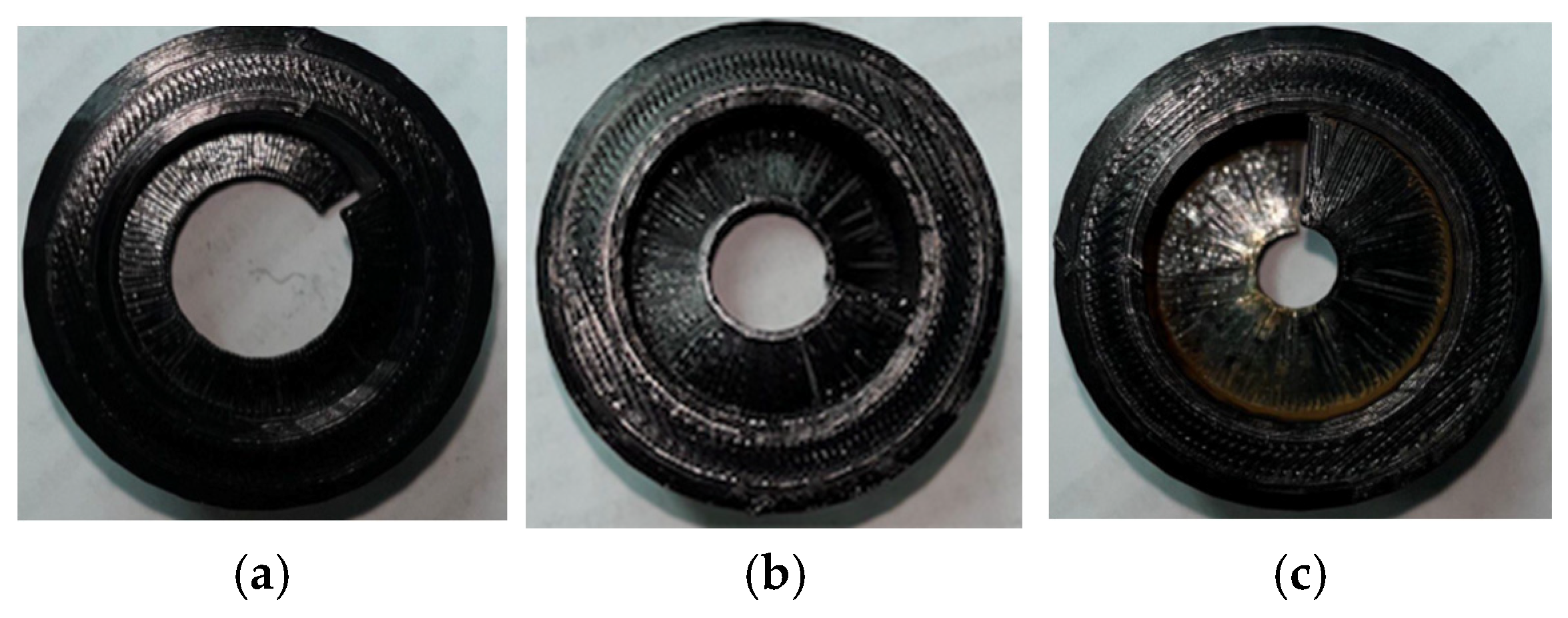
| Reason for lifting the pump | Wear of the turbulizer of the intake valve | Clamping of the pump | Wear of the turbulizer of the intake valve | Wear of the turbulizer of the intake valve | Mechanical impurities from pipes | Wear of the turbulizer of the intake valve |
| Pump operating time with newly designed valves, days | 37 | 101 | 78 | 85 | 15 | 77 |
Disclaimer/Publisher’s Note: The statements, opinions and data contained in all publications are solely those of the individual author(s) and contributor(s) and not of MDPI and/or the editor(s). MDPI and/or the editor(s) disclaim responsibility for any injury to people or property resulting from any ideas, methods, instructions or products referred to in the content. |
© 2025 by the authors. Licensee MDPI, Basel, Switzerland. This article is an open access article distributed under the terms and conditions of the Creative Commons Attribution (CC BY) license (https://creativecommons.org/licenses/by/4.0/).
Share and Cite
Zaurbekov, S.; Zaurbekov, K.; Balgayev, D.; Boiko, G.; Aksholakov, E.; Klyuev, R.V.; Martyushev, N.V. Design Optimization of Valve Assemblies in Downhole Rod Pumps to Enhance Operational Reliability in Oil Production. Energies 2025, 18, 3976. https://doi.org/10.3390/en18153976
Zaurbekov S, Zaurbekov K, Balgayev D, Boiko G, Aksholakov E, Klyuev RV, Martyushev NV. Design Optimization of Valve Assemblies in Downhole Rod Pumps to Enhance Operational Reliability in Oil Production. Energies. 2025; 18(15):3976. https://doi.org/10.3390/en18153976
Chicago/Turabian StyleZaurbekov, Seitzhan, Kadyrzhan Zaurbekov, Doszhan Balgayev, Galina Boiko, Ertis Aksholakov, Roman V. Klyuev, and Nikita V. Martyushev. 2025. "Design Optimization of Valve Assemblies in Downhole Rod Pumps to Enhance Operational Reliability in Oil Production" Energies 18, no. 15: 3976. https://doi.org/10.3390/en18153976
APA StyleZaurbekov, S., Zaurbekov, K., Balgayev, D., Boiko, G., Aksholakov, E., Klyuev, R. V., & Martyushev, N. V. (2025). Design Optimization of Valve Assemblies in Downhole Rod Pumps to Enhance Operational Reliability in Oil Production. Energies, 18(15), 3976. https://doi.org/10.3390/en18153976