1. Introduction
Global renewable energy capacity reached 4400 GW in 2024, with wind energy, one of the leading renewable sources, contributing 25% of this capacity [
1]. The success of wind energy arises from its improving cost competitiveness compared to conventional sources [
2]. The economics of wind energy promote the scaling of wind turbines to larger rotor diameters and higher hub heights. This is partly because the Annual Energy Production (AEP) of a single wind turbine depends on its power rating and site wind conditions. For a typical wind turbine, the extracted power scales with the square of the rotor radius and the cube of the incoming wind speed. By increasing rotor diameter, turbines sweep a larger area, and by raising hub height, they tap into faster winds. Consequently, modern wind turbines have undergone rapid upscaling, with multi-megawatt power ratings being common in new installations. Upscaling land-based wind turbines brings new engineering and logistical challenges. Complex terrains and surface roughness result in pronounced wind shear and turbulence, creating large differential wind speeds across the rotor that induce stochastic and dominant once-per-revolution (1P) loads on the turbine blades, yaw bearing, and tower. Such undesired forces drive both fatigue and extreme-load considerations on the design requirements. From a logistical perspective, transporting ever-longer, monolithic blades by roadways imposes severe transportation constraints. Further, a key social constraint is community resistance to new wind farm installations, driven by concerns over noise pollution and aesthetic impacts.
Offshore wind energy has emerged as a viable alternative to the predominant land-based wind energy. Most common offshore wind turbines are installed in shallow waters (<60 m), on substructures fixed to the seabed. However, a majority of the global offshore wind resource is found over deep ocean waters where fixed-bottom offshore installation becomes economically unfeasible. Floating offshore wind turbines (FOWTs) are seeing a surge in interest as they address some of these challenges. FOWTs are installed on floating platforms, typically attached to the seabed using mooring lines. Owing to their installation in deep waters (>60 m), FOWTs tap into superior wind resources characterized by consistently high wind speeds with lower turbulence and wind shear due to the smoothness of the ocean surface [
3]. Manufacturing and assembling FOWT components at ports and transporting them using ships or tugboats eases logistics. Moreover, the distant offshore locations minimize societal objections as they can be built away from populated areas.
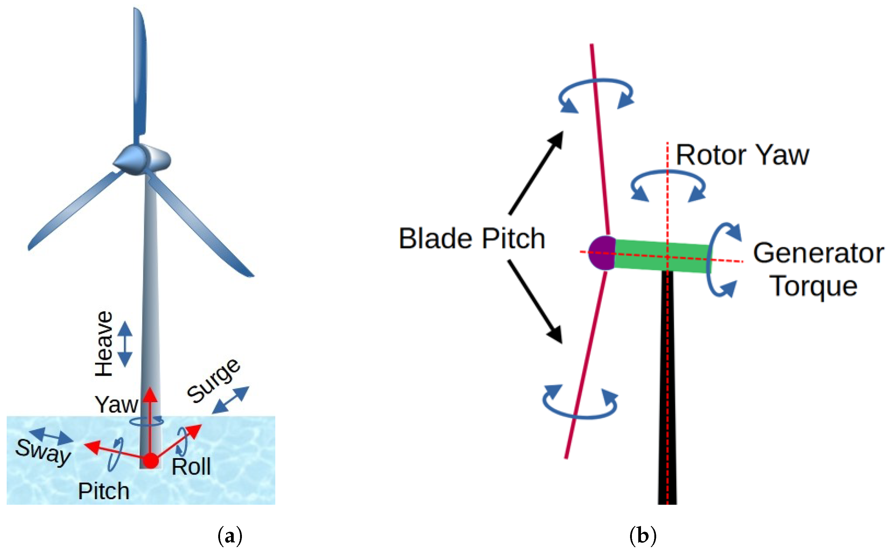
The dynamics of the FOWT platform motion introduce new engineering challenges and opportunities. The combined effects of wind and wave disturbances can induce translational and rotational motion in FOWTs. Such undesired movements can compromise power quality, exacerbate mechanical loading, and, under extreme conditions, may jeopardize FOWT stability.
Figure 1a describes the translations and rotations for the FOWT platform. Standard wind turbine controllers tuned for land-based turbines often underperform on FOWTs. The coupling between generator speed control and platform dynamics can introduce negative damping in above-rated operation, whereby blade pitch actuation amplifies platform pitch oscillations [
4,
5]. Past research has mitigated platform pitch oscillations by simply detuning the blade pitch control gains at the cost of worse generator speed regulation performance [
4,
6]. More advanced techniques have incorporated direct feedback of platform motion [
7] or used individual pitch control (IPC), which provides independent pitch commands to each turbine blade [
8] to improve platform pitch stability. Single-point moored FOWTs are particularly vulnerable to yaw drift (weathervaning effect) [
9] driven by wind shear or rotor coning and shaft tilt angles, degrading rotor alignment with the wind and reducing power capture. To counteract this misalignment, both collective pitch control in dual-rotor FOWTs [
10] and rotor yaw control and IPC strategies [
11,
12] have been studied to reduce yaw error and restore optimal rotor alignment in single-point mooring configurations.
Conversely, the inherent six DOF motion of FOWT platforms can be harnessed to enhance turbine and wind farm level performance. FOWTs have been shown to generate more power when pitched into the oncoming wind [
13]. This is mainly due to the rotor shaft tilt angle that offsets the rotor away from the wind to maintain clearance between the blades and the tower. Performance improvements could be achieved at the floating wind farm level through controlled wake interactions. Wake deflection steers upstream wakes away from downstream turbines by deliberately shifting [
14,
15] or pitching [
16] the platform about its equilibrium, thereby improving farm-level power capture. Wake mixing, in contrast, accelerates wake recovery by inducing targeted platform oscillations that promote turbulence and momentum transfer, re-energizing the flow downstream. Recent work has demonstrated passive FOWT designs that exploit platform yaw motions to achieve wake mixing [
17]. Free-floating or unmoored FOWT concepts have recently emerged that use a portion of the energy produced by the wind for station-keeping [
18]. Such systems, being untethered, are theoretically capable of locomotion to ‘chase the wind’ [
19]. Most unmoored FOWT concepts use some configuration of thrusters or propellers to achieve displacement or to remain stationary under external loads [
20,
21].
FOWT platform design remains an active area of research [
22,
23,
24,
25]. However, three popular platform designs have emerged, as shown in
Figure 2: spar-buoy, semi-submersible, and tension-leg platforms (TLPs). Each design uses distinct stability mechanisms in the presence of wind and wave disturbances, though all designs use mooring systems to avoid drift. The spar-buoy employs a deep draft and heavy ballast for gravitational and hydrodynamic stabilization, whereas the semi-submersible platform leverages a large surface area and buoyancy. Both utilize slack mooring lines, permitting limited platform motion about their nominal position. In contrast, the TLP relies on a taut mooring system, drawing stability from the tension in the mooring lines. Traditional wind turbine actuators such as the blade pitch drives, generator torque, and rotor yaw drive (as shown in
Figure 1b) have some control over FOWT platform motion. Blade pitch actuators can be especially used to influence platform pitching [
26]. The rotor yaw drive can affect platform yaw and sway motion [
14,
15]. However, the use of these actuators for platform motion typically comes at the cost of reduced performance in either power capture or structural loading. In addition, these actuators may not have sufficient control authority to reliably control platform motion. For example, ref. [
27] studied a wave feed-forward collective blade pitch control strategy to reduce wave-induced platform pitching motion and discovered that large fluctuations in the blade pitch were needed for minor reductions in platform motion. Research into novel actuated floating platforms is attempting to address the challenges of FOWTs and overcome the limitations of using traditional actuators for platform motion control through passive and active strategies.
Figure 2 also shows some of the novel platform concepts. The SpiderFLOAT platform [
28] proposes a lightweight flexible floater with actuated tension cables and actively ballasted buoyancy cans to control FOWT orientation [
13,
29,
30]. Active ballasting has also been studied for the semi-submersible type platforms for keel correction and wake deflection [
16,
31,
32,
33]. For the TLP, an active mooring line actuator has been investigated to reduce platform roll motion and tower side-side bending fatigue loads [
34]. Mooring line length control has been studied for FOWT reorientation/repositioning [
35]. The T-omega platform uses a single mooring line configuration and intends to use active control techniques to ‘weathervane’ the FOWT system according to changing wind direction [
36].
Despite extensive research into novel FOWT configurations and actuator technologies, there is currently no unified framework for rapidly evaluating emerging platform designs and motion control schemes at the conceptual stage. Passive stabilization methods such as tuned-mass dampers [
37] or mooring configurations [
17] are unable to adapt to changing conditions or shifting control objectives. Traditional PID-based controllers, while simple, ignore complex coupled dynamics and require extensive gain-scheduling to perform across nonlinear operating regions. By contrast, the Lyapunov-based approach developed in this work yields closed-form control laws for all six translational and rotational DOFs with global stability, establishing an analytical foundation to guide the design, placement, and sizing of actuators. This paper introduces a systematic methodology for deriving unconstrained analytical control laws early in the design process. Our primary contribution is an actuator-agnostic, nonlinear control framework that governs all six degrees-of-freedom (DOFs) of a FOWT platform. The framework uses reduced-order analytical (ROA) modeling of FOWT systems to derive the control laws using Lyapunov’s direct method [
38]. While higher-fidelity FOWT simulation tools such as the popular OpenFAST [
39] provide a fully coupled aero-hydro-servo-elastic simulation with up to 23 DOFs, its extensive parameterization of the turbine and the environment makes it complex, intractable, and thus unsuitable for extracting closed-form system equations for Lyapunov-based control. Such higher-fidelity tools are also computationally expensive for extensive design-space exploration. In contrast, the ROA model yields closed-form, symbolic system matrices that enable the application of Lyapunov’s direct method and execute in less than half the time of an equivalent OpenFAST simulation. The resulting control laws are validated using this higher-fidelity simulation tool, demonstrating performance across a variety of scenarios. Potential applications are outlined, and directions for future research are identified.
The remainder of this paper is organized as follows.
Section 2 will present the platform control framework and demonstrate its use to derive unconstrained control laws using Lyapunov’s direct method.
Section 3 will present results comparing the analytical model to higher-fidelity simulations. It will also show the performance of the unconstrained control laws.
Section 4 will discuss the findings, limitations, and future research directions, and
Section 5 will conclude the paper.
2. FOWT Platform Control Framework
The proposed platform control development framework is described in
Figure 3 as a four-stage process that begins with conceptualizing a novel FOWT system. Advanced FOWT concepts often begin with novel platform geometries, mooring systems, and actuator layouts. Yet, faithfully modeling blade and tower flexibility, drivetrain torsion, unsteady aerodynamics, wave kinematics, hydrodynamic damping, and nonlinear mooring forces can result in very high-order models that are untenable for control synthesis or rapid design exploration. To address this, the framework uses a reduced-order model that assumes rigid, multi-body dynamics, with six DOF platform motion and the rotor spin. This preserves the critical rotor–platform coupling, enables formal Lyapunov-based controller design, and facilitates early-stage analysis without resorting to costly high-fidelity simulations. The conventional wind turbine control comprising of the generator torque control and collective blade pitch control can be derived through established methods such as the Reference Open-Source COntroller (ROSCO) framework [
40]. Optionally, a rotor yaw control may be set up if needed by the application. Next, unconstrained, actuator-agnostic control laws to control six DOF platform motion are derived using Lyapunov’s direct method and the reduced-order model. These control laws generate an ideal vector of generalized forces and moments, assuring asymptotic convergence without imposing constraints of hardware realization. This allows for early-stage actuator design and analysis. The unconstrained force and moment profiles can guide actuator sizing, placement, and bandwidth specifications without resorting to repeated high-fidelity simulations. With this approach, the framework aims to accelerate innovation in floating offshore wind turbine concepts. Future work will translate these idealized vectors into achievable actuator commands through control allocation. Traditional turbine actuators and novel hardware, such as active ballast pumps and cable tensioners, may be studied for the platform motion control application.
The following subsections detail the first three stages of the framework. As a case study, we adopt the NREL–5 MW reference turbine mounted on the OC3 Hywind spar-buoy platform [
41,
42]. The goal of this paper is to illustrate the derivation of unconstrained, Lyapunov-based platform control laws using reduced-order analytical models, rather than to propose novel platform or actuator designs. The design and allocation of actuators to implement the unconstrained control laws (the fourth stage of the framework) are left to future work.
2.1. Reduced-Order Model
High-fidelity FOWT models account for blade and tower elasticity, drivetrain torsion, platform deformations, and detailed fluid–structure interactions, commonly having model descriptions with upwards of twenty DOFs. While important for structural and fatigue analysis, that level of complexity is unfeasible for analytical control development. Moreover, deformations exert limited influence on the relevant rigid-body platform motions. While many models reduce the complexity of FOWT dynamics [
43,
44], this work adopts a reduced-order modeling strategy based on [
45], which makes rigid-body assumptions for the primary FOWT components, omits higher-order elastic and drivetrain dynamics, and uses a Lagrangian approach to produce a seven-DOF representation that is better suited for Lyapunov-based control development. This subsection describes the simplified rotor and platform dynamics that incorporate the reduced-order model.
Wind turbines operate by converting the kinetic energy in the wind into electrical energy using a rotor driving a generator under aerodynamic torque. The power (
) available in the wind for a rotor with a radius
R is calculated as [
46]:
where
is the air density and
is the wind speed experienced by the turbine. However, not all the power available in the wind can be captured by the turbine. In fact, the power (
P) captured by the rotor at any instant is given by [
46]:
where
is the power coefficient for the turbine, which is the ratio of the rotor power (
P) to the available wind power (
), and is a function of the blade pitch angle
, and the tip-speed ratio (TSR)
. TSR is defined as the ratio of the linear speed of the blade tip to the speed of the incoming wind:
Here
is the rotor angular speed. The maximum theoretical limit for the power coefficient is derived using the actuator disc model and is found to be
[
46]. It is evident from Equations (
2) and (
3) that the power captured by a wind turbine is a function of the wind speed, the rotor speed, and the blade pitch angle. The rotor speed is primarily affected by two torques: the aerodynamic rotor torque (
) from the wind and the control torque (
) from the generator torque actuator. The simplified rotor dynamics are given by
where
is the rotor roll inertia about the
x-axis.
As illustrated in
Figure 4, the FOWT used in this research is modeled as a combination of four rigid bodies, representing the rotor, nacelle, tower, and platform, each characterized by its center-of-mass (COM,
) and moment-of-inertia (MOI,
), where subscript
for rotor, nacelle, tower, and platform, respectively. The kinematics are defined using two coordinate reference frames. The inertial frame,
, is fixed at the COM location of the undisplaced platform with its
-axis pointing in the downwind direction, the
-axis in the crosswind direction, and the
-axis aligned with the local vertical. The body-fixed frame,
, is attached to the platform COM, with the
-axis aligned with the rotor spin axis, the
-axis along the tower centerline, and the
-axis completing the right-handed system. The rotor shaft-tilt and preconing angles are neglected in the ROA model. This reduced-order FOWT model considers seven degrees of freedom: three translational motions (surge along
, sway along
, and heave along
), three rotational motions (roll about
, pitch about
, and yaw about
), and the rotor spin about the
-axis.
The platform translation is given by vector
, measured as the vector from the origin of
to the origin of
:
where
,
, and
are the surge, sway, and heave motions of the FOWT. The superscript, if present, denotes the frame in which the vector is defined. The rotation of the FOWT is measured using the 3-2-1 Euler angle set
, commonly known as the Roll-Pitch-Yaw (
-
-
) sequence that transforms the inertial frame to the platform frame:
The rotor DOF is accounted for with the rotor speed
about the
axis:
The linear velocity
of the system is simply the time derivative of the position,
and the angular velocity
is given as in [
47]:
The equations of motion for the FOWT system are calculated using Lagrangian dynamics from the kinetic and potential energies of the four rigid bodies as described in [
45], where the resulting equations of motion can be written in matrix form:
where
and
are the gravitational force and moment,
and
are the modeled external forces and torques,
and
are the aerodynamic and generator torques, and the matrix
is in the block matrix form
where
is the total mass matrix,
is the system moment of inertia matrix, and
, where
is the rotor spin inertia.
with
and
, where
and
are the vertical distances from the platform COM to the rotor and the tower COMs, respectively, and
and
are horizontal distances from the tower centerline to the nacelle and rotor COMs, respectively. Finally,
is the cross coupling matrix:
where
denotes the skew-symmetric matrix representing the vector cross product operation defined as
2.1.1. Aerodynamics
In addition to the aerodynamic torque that spins the rotor, the wind exerts an aerodynamic rotor thrust along the
-axis, which induces a pitching moment and a surge force on the floating platform. The aerodynamic torque
and rotor thrust
are modeled using the actuator disc model with the turbine power (
) and thrust (
) coefficients as in [
48,
49]:
where
is the relative wind speed parallel to the rotor spin axis.
2.1.2. Hydrostatics
The hydrostatic buoyancy force is a function of the instantaneous geometry of the submerged platform:
where
is the water density,
g is the gravitational constant, and
is the instantaneous volume of the submerged platform geometry. Subsequently, the hydrostatic moment can be calculated as the moment about the COM exerted by the vertical force
on the center of buoyancy.
2.1.3. Hydrodynamics
The hydrodynamic loads are calculated using Morison’s equation for a cylinder [
50] in still water conditions, with wave and current dynamics scheduled for future work.
2.1.4. Mooring Dynamics
The modeled FOWT employs three slack mooring lines connected to the platform through fairleads and the seabed using anchors. They are uniformly distributed
apart in the horizontal plane, both at the platform connections (fairlead points) and at the seabed connections (anchor points). The mooring tension is modeled using quasi-static models of catenary mooring lines as explained in [
51]. For each mooring line, the horizontal and vertical distances between the fairlead and the anchor, and the angle of the horizontal projection with the
axis (
) are used to calculate the horizontal (
) and vertical (
) components of mooring tension in a quasi-static manner. The two cases of a partially resting on the seabed or a fully suspended mooring line are accounted for using appropriate models [
45]. The resulting tension on the platform due to a mooring line is given as:
The total force and moment acting on the FOWT due to the mooring system is the sum of the forces and moments due to individual mooring lines.
2.2. Wind Turbine Control
The rating of a wind turbine signifies its desired maximum power production capacity. According to Equation (
2), power capture grows with the cube of wind speed.
Figure 5a depicts a typical power curve, illustrating power capture relative to wind speed. Given varied control objectives across wind speeds, the curve is segmented into distinct control regions:
Region 1: At minimal wind speeds, wind power can’t offset system losses, so the turbine remains inactive, outputting zero power.
Region 2 (Below-rated operation): Beyond the cut-in wind speed (), the goal is to optimize power capture up to the rated wind speed (), where power matches the turbine’s rated power.
Region 3 (Above-rated operation): For wind speeds surpassing , the objective shifts to maintaining power production at its rated value. This persists until reaching the cut-out wind speed (), beyond which the turbine is halted due to high aerodynamic loads.
Region 4: This represents the inoperative zone after the cut-out wind speed.
2.2.1. Generator Torque Control
In Region 2, generator torque is the primary actuator for maximizing power. The
surface of a wind turbine describes
variations due to changes in TSR and blade pitch angle. The peak value
is achieved at optimal values of TSR (
) and blade pitch angle (
), maximizing the turbine’s power capture. Therefore, the goal in Region 2 is to maintain operation at the (
) coordinate. Here, the blade pitch is set to the optimal value
, and the TSR is regulated to
, ensuring the turbine operates at
. The nonlinear control law used to implement Region 2 control is given by [
49]:
where
is the generator speed which is related to the rotor speed through the gearbox ratio
as
and the optimal gain
is calculated as [
49]
2.2.2. Collective Blade Pitch Control
In Region 3, the primary control objective is to regulate power production at the turbine’s rated capacity. The power output by the turbine generator is given by [
49]:
To regulate power in Region 3, the generator torque actuator is kept saturated at its rated value
and blade pitch actuators are used to manipulate the aerodynamic torque on the rotor to track the rated generator speed (
). This is achieved using the proportional-integral (PI) collective blade pitch control [
52]:
where
is the generator speed tracking error.
and
are the scheduled proportional and integral gains, respectively. The gain scheduling is necessary due to the nonlinear relation between blade pitch angle (
) and power (
P) across wind speeds. Smaller adjustments in blade pitch are needed at higher blade pitch angles to achieve similar control performance [
41]. The complete control scheme for wind turbines described above is summarized in
Table 1 and the standard control block diagram is shown in
Figure 5b.
2.3. Platform Control Laws
Towards the objective of developing control techniques for the 6-DOF FOWT platform, unconstrained control laws are first developed using Lyapunov’s direct method [
38] for the system dynamics from Equation (
10) to control rotational and translational platform motion. The approach for developing the control laws is described below.
Consider
and
to be position and velocity like coordinate vectors with kinematic and dynamic equations given by
where
is the kinematic function relating the states to the rates,
is a symmetric positive definite mass or inertia type matrix,
is the system dynamics including modeled external forces or torques and
is the required unconstrained control vector. A Lyapunov candidate function is chosen to be of the form
where
is a symmetric positive definite design matrix. The time derivative of the Lyapunov function is given as
Substituting Equations (
23) and (
24) and setting
equal to a negative definite function for an asymptotically stable system, we get
where
is another symmetric positive definite design matrix. Equating and solving for
we get
Rotational Control Law: From Equations (
9) and (
10), we have the rotational equations of motion. To use the above approach for control law development with
as
and
as
, we select the Lyapunov candidate function.
where
is a symmetric positive definite gain matrix. Following steps (
26) through (
28), the unconstrained control torque (
) is derived:
Here,
is also a symmetric positive definite gain matrix,
is the kinematic matrix from Equation (
9),
is the cross-product matrix operator given in Equation (
14), and
contains the external moments that are to be compensated by the control. The remaining terms in Equation (
30) are defined in Equations (
5)–(
13). Note that if all the external moments modeled in the ROA are countered by the unconstrained control torque
, the closed-loop system dynamics for rotational motion can be written as
If the inertia matrix
is diagonal, for small angular displacements
, with diagonal gain matrices
and
, the closed-loop dynamics can be approximated by a set of three linear, uncoupled equations.
Translational Control Law: For deriving the translational control force, with the motion described by Equations (
8) and (
10) and setting
as
and
as
we consider the Lyapunov candidate function given below.
with
being a diagonal positive definite gain matirx. Again, following steps (
26) through (
28), the unconstrained control force (
) is derived.
is designed as a diagonal positive definite gain matrix, and
is the sum of external forces to be compensated by the control with the remaining terms as defined in Equations (
5)–(
13). With
being a diagonal mass matrix, when this translational control law counters all modeled external forces, it results in the following linear, uncoupled closed-loop dynamics:
While these unconstrained control laws, which assume ideal actuators, have limited practical application, they can be useful for guiding the design, sizing, and evaluation of platform actuators, which will be a focus in future work.
3. Results
OpenFAST [
39] is a widely used open-source simulation tool developed by the National Renewable Energy Laboratory (NREL) to simulate fully coupled aero-hydro-servo-elastic responses of wind turbines, including floating offshore systems. It integrates blade aerodynamics, structural dynamics, wave and current hydrodynamics, mooring mechanics, and control system modules into a unified modular framework. To evaluate the ROA model’s performance in emulating FOWT behavior, we conducted 700-s simulations under steady, below-rated wind conditions with still water using the baseline wind turbine control (
Section 2.2), which was implemented in Matlab/Simulink [
53,
54], for both the ROA model and the higher-fidelity OpenFAST.
Figure 6 shows the generator speed and platform displacements time-averaged over the final 600 s of each run after discarding the first 100 s of OpenFAST transients. Overall, the ROA model successfully captures the key trends in generator speed and platform motion. Modest offsets in mean pitch and heave reflect the ROA model’s simplified representation of aerodynamic, mooring, and hydrodynamic loads compared to OpenFAST’s detailed physics. The ROA model also ignores the effects of rotor shaft tilt and coning angles, which impact the FOWT’s surge, pitch, and generator speed behavior. On the same platform, the ROA model runtime measured at roughly 230 s versus about 440 s per simulation for the equivalent OpenFAST run. This significant reduction in computational costs, together with the ROA’s closed-form system and control-law expressions, makes it possible to conduct rapid early-stage parameter sweeps and directly synthesize Lyapunov-based controllers without resorting to a detailed design process.
The platform control laws derived in the previous section are implemented in Matlab/Simulink for testing with the ROA model and OpenFAST. The OpenFAST source code was modified to allow the application of unconstrained control laws to the platform through the Simulink interface. It is important to note for the following results that only the aerodynamic force and torque on the platform are compensated through the modeled external forces (
) and torques (
) in the control laws of Equations (
30) and (
34), respectively. The restoring mooring and hydrodynamic effects are left as unmodeled components. Simulations are performed at 8 m/s steady and turbulent wind speed with still water and irregular wave conditions, using the NREL-5MW reference turbine on the OC3-Hywind spar buoy platform.
Figure 7 compares simulations between OpenFAST and the ROA model with non-zero initial conditions of
rotation about each platform axis and a 3 m displacement along each inertial axis. The error metrics for these simulations presented in
Table 2 and
Table 3 quantify the effects of progressively more complex dynamics on control performance in OpenFAST simulations as compared to the expected control performance in the ROA model. These metrics present the average root-mean-square error (RMSE) and worst-case maximum absolute error (MaxAE) deviation of the higher-fidelity OpenFAST simulation cases from the ROA model in steady-state. To exclude start-up transients, we restrict the timeseries to the final 100 s of the 200-s simulations. Defining
N as the number of retained samples, the RMSE and MaxAE for each DOF are calculated as
Case 1 assumes a rigid turbine, neglects blade coning and shaft tilt, and is in still water. Here, the ROA model captures the platform motion with a surge RMSE of 0.72 m and a maximum absolute surge error of 0.76 m. The sway, heave, roll, and yaw errors remain no larger than 0.03 m or 0.02°, demonstrating a good baseline fidelity. Introducing rotor coning and shaft tilt in Case 2 increases the yaw maximum error to 0.01°, reflecting additional kinematic couplings absent from the simplified geometry. When rotor and tower flexibility are enabled in Case 3, the generator speed mismatch grows markedly (RMSE 4.95 RPM, MaxAE 6.00 RPM), indicating that elastic blade–tower modes significantly influence rotor dynamics. Wave excitation accentuates hydrodynamic and elastic effects. In Case 4 with wind-aligned irregular waves, heave RMSE increases to 0.04 m, and the maximum heave error to 0.10 m, while the maximum surge and pitch errors rise to 0.96 m and 0.42°, respectively. Other platform motion DOFs mostly remain within baseline error bounds. The crosswind waves in Case 5 most significantly affect the sway (RMSE 0.02 m, MaxAE 0.05 m) and the roll (RMSE 0.09°, MaxAE 0.25°) DOFs, whereas the surge and pitch errors return to Case 1 levels. These wave-induced deviations primarily affect higher-frequency components, yet even peak errors (0.96 m surge, 0.42° pitch) are small relative to full-scale platform motions. Although elastic modes and wave forcing introduce DOF-specific deterioration of control performance, the ROA model retains accurate representation of the dominant closed-loop dynamics for early, concept stage control design.
Figure 7a shows the platform DOF timeseries for ROA model and OpenFAST Cases 4 and 5. The roll, yaw, sway, and heave outcomes align closely with the higher-fidelity OpenFAST results, although crosswind waves in Case 5 significantly affect the roll performance. The reduced-order model’s omission of certain aerodynamic, hydrodynamic, and mooring loads and the control laws’ compensation of only the simplified aerodynamic function produce persistent steady-state errors in pitch and surge correction. Since these control laws do not include integral compensation in their current form, steady-state errors remain uncorrected. Augmenting the control laws with an integral term would eliminate such biases from unmodeled forces and torques and further improve platform motion regulation.
Figure 7b shows the demanded control forces and torques for the ROA model and OpenFAST cases. Considering the steady-state errors, a good match is observed between the ROA model-predicted and actual control signals.
In
Figure 8, platform control (where controllers from both
Section 2.2 and
Section 2.3 are used, see
Figure 3) is compared against a baseline (
Section 2.2 only, with no platform control) in OpenFAST under 8 m/s steady wind and irregular waves, with zero initial conditions.
Figure 8a shows that the OC3-Hywind semisubmersible platform experiences substantial motion in operation. Especially, in the surge and pitch DOFs, aerodynamic loading in below-rated winds induces steady-state deflections of roughly 8 m and 2.5°, respectively, with the baseline controller. These amplitudes can be even worse near rated operation and under combined wind–wave loading. For example, ref. [
55] demonstrated that surge displacement at rated wind speeds exceeds 20 m and platform pitch surpasses 5° for the OC3-Hywind platform with the NREL-5MW wind turbine. Assuming ideal actuators, augmenting the proposed platform control law dramatically reduces steady-state motions across all six platform DOFs. The corresponding force and torque demands in
Figure 8b reveal that pitch and surge require the largest sustained inputs to counteract aerodynamic rotor thrust. It is noted that most DOFs initially have a high actuation demand for a short duration, which then reduces at the steady state. While controlling for such large FOWT displacements ultimately hinges on novel actuator designs and their optimal placement, recent studies highlight several promising strategies. Catenary mooring line–length control, for example, can shift the mean platform surge by as much as 12.5 m by retracting 15 m of a single mooring line at rated wind conditions [
35]. Active water-ballast systems offer another avenue. Ref. [
16] studied vertical wake deflection for a semi-submersible FOWT platform. By differentially pumping roughly 500 m
3 of water between the columns of the semi-submersible, a pitch of 20° could be attained within 300 s. Rotor yaw for repositioning of FOWTs with extended mooring lines has also been studied for semi-submersible platforms. At 8 m/s wind, a 6° yaw misalignment yields steady-state sway of around 80 m for 970 m long mooring lines in under 1000 s [
14]. Actuator saturation and bandwidth limits impacting this initial transient response will be considered in future research.
Figure 9 presents the time histories (where the first 100 s of startup transients have been omitted) alongside mean and standard-deviation statistics for power, rotor thrust (including gravitational loading), and tower-base fore–aft bending moment for the simulation case in
Figure 8. With platform control engaged, mean power rose by 1.3% while its variability dropped by 64.6%, mean rotor thrust reduced by 7.8% with a 37.6% reduction in standard deviation, leading to a mean tower-base bending load decrease of 30.9% alongside a 34.9% reduction in standard deviation.
Figure 10 illustrates the first 100 s of the platform surge and pitch response, together with the corresponding surge force and pitch moment commands, from a 700-s turbulent 8 m/s wind simulation with irregular waves. The baseline (with no platform control) is shown in blue dash-dotted curves, and the unconstrained platform control is shown in red curves. For a preliminary test of actuator constraints, actuation along each platform DOF is saturated at 50% of their peak demand from the unconstrained simulation (shown in purple curves). For the baseline, surge motion under aerodynamic thrust grows steadily to over 14 m and the platform pitch almost reaches 5°. Under unconstrained control, platform surge and pitch are significantly attenuated, with their peaks reduced by over 85%. The control performance degrades when a 50% saturation is applied to the actuators. However, the control laws still achieve more than 65% reduction in peak surge and pitch motion compared to the baseline.
Figure 11 quantifies the percent changes relative to the baseline, in steady-state mean and standard deviation of the power output, generator speed, tower fore–aft loading, and all six platform DOFs for both platform control scenarios (unconstrained and with 50% saturation). The unconstrained platform control produces a modest increase in mean power of approximately 1.88% but a slight rise in its variability of 5.5%, while reducing tower fore–aft load by roughly 30% in mean and 32% in variability. With a 50% actuator saturation, the mean power gain reduces slightly to 1.74%, but the tower-load reductions reduce to roughly 27% in mean and 19% in variability. All three translational DOFs exhibit greater than 90% reductions in the mean and over 70% in standard deviation under unconstrained control. Even with the 50% saturation, average platform displacements are attenuated by over 80% and variability by over 70% (except for heave, where the reduction in standard deviation drops to 15%). The rotational DOFs are similarly suppressed: unconstrained control yields mean and variability reductions exceeding 75% and 80%, respectively, and the 50% saturated control continues to achieve mean reductions in the 70–85% range. These preliminary results demonstrate that the Lyapunov-based control laws retain substantial performance even with significantly limited actuator authority, highlighting their robustness to practical saturation constraints.
4. Discussion
This research introduces a Lyapunov-based nonlinear control framework that uses a ROA FOWT model to derive analytical control laws for six DOF platform motion control. The use of this framework was demonstrated for the NREL-5MW reference turbine on the OC3 Hywind spar-buoy platform. A Lagrangian approach was adopted to derive a 7-DOF ROA model of this FOWT configuration. By leveraging Lyapunov’s direct method, unconstrained translational and rotational control laws were derived to mitigate FOWT platform motion. They were limited in this initial research to compensate for the aerodynamic force and moment on the rotor, with all other external effects being unmodeled. Validation against higher-fidelity OpenFAST simulations confirmed that the ROA model reasonably captures the dominant rotor and platform dynamics while offering twice as fast simulation times compared to OpenFAST. However, neglecting elastic modes and fluid-structure interactions yields deviations in expected and actual platform control performance.
The control laws were implemented with both the ROA model and OpenFAST model using Matlab/Simulink R2024b. Steady-state errors were observed both in ROA and OpenFAST simulations due to unmodeled effects and a lack of integral action in the control laws. For a steady wind speed of 8 m/s, the control performance with increasing levels of scenario complexity was compared with the expected control outcomes of the ROA model. It was observed that wave-structure interactions had the most effect on control performance degradation, and the alignment of waves dictated the DOFs that were most affected. While turbine flexing did not significantly affect platform control performance, it resulted in a worse generator speed tracking performance for the FOWT.
To assess the benefits of platform control, it was compared against a baseline (no platform control) within OpenFAST. It was evident that large platform motion is expected under operation, and a significant action will be required to mitigate it. Especially, the platform surge and pitch DOFs that are directly affected by aerodynamics need the most sustained control effort for effective counteraction. Certain novel actuators, such as active mooring lines or water ballasts, can be studied as promising solutions. The proposed control laws substantially reduce platform motion within ideal actuator assumptions. Under steady wind conditions, the turbine performance improves with platform control as the mean power capture increases, while power fluctuations reduce. Both rotor thrust and tower-base bending moments and load fluctuations are significantly reduced. Power gain and tower load reduction were also observed under turbulent wind and irregular wave scenarios; however, a slight increase in power variations was noted. Actuator saturation limits equal to 50% of the peak unconstrained actuator requirements were applied to obtain preliminary insights into the effects of constraints on control performance. Although imposing actuator saturation produces a modest reduction in platform-motion attenuation, the Lyapunov-based control laws still significantly suppress displacements and rotations relative to the baseline. This limited performance degradation demonstrates that the control design maintains considerable robustness despite substantial actuator constraints. These benefits underscore the promise of active platform stabilization for enhancing energy yield and mitigating loads and fatigue damage, to ultimately lower the levelized cost of floating wind energy.
The framework yields precise specifications for required control forces and moments, but it does not yet translate those demands into actuator commands or account for hardware constraints such as saturation and bandwidth limits. Real-world implementation of the control laws will require a control allocation (the fourth step of this framework shown in
Figure 3) to translate the generalized commands into feasible actuator signals. The control laws in their current form also show vulnerability to unmodeled effects. Refinements, most notably the addition of integral action, will eliminate such residual errors from unmodeled disturbances. Extensions to non-zero reference tracking will enable coordinated platform motions for wake-steering applications in floating wind farm settings. Embedding this methodology within wind farm-level studies promises to unlock new strategies for wake mitigation and collective optimization through active platform control.


