Article

Experimental Study on Co-Firing of Coal and Biomass in Industrial-Scale Circulating Fluidized Bed Boilers

State Key Laboratory of Clean Energy Utilization, Zhejiang University, Hangzhou 310027, China
*
Author to whom correspondence should be addressed.
Energies 2025, 18(14), 3832; https://doi.org/10.3390/en18143832
Submission received: 26 June 2025 / Revised: 13 July 2025 / Accepted: 16 July 2025 / Published: 18 July 2025
(This article belongs to the Section A4: Bio-Energy)

Abstract

Based on the low-carbon transition needs of coal-fired boilers, this study conducted industrial trials of direct biomass co-firing on a 620 t/h high-temperature, high-pressure circulating fluidized bed (CFB) boiler, gradually increasing the co-firing ratio. It used compressed biomass pellets, achieving stable 20 wt% (weight percent) operation. By analyzing boiler parameters and post-shutdown samples, the comprehensive impact of biomass co-firing on the boiler system was assessed. The results indicate that biomass pellets were blended with coal at the last conveyor belt section before the furnace, successfully ensuring operational continuity during co-firing. Further, co-firing biomass up rates of to 20 wt% do not significantly impact the fuel combustion efficiency (gaseous and solid phases) or boiler thermal efficiency and also have positive effects in reducing the bottom ash and SOx and NOx emissions and lowering the risk of low-temperature corrosion. The biomass co-firing slightly increases the combustion share in the dense phase zone and raises the bed temperature. The strong ash adhesion characteristics of the biomass were observed, which were overcome by increasing the ash blowing frequency. Under 20 wt% co-firing, the annual CO2 emissions reductions can reach 130,000 tons. This study provides technical references and practical experience for the engineering application of direct biomass co-firing in industrial-scale CFB boilers.

1. Introduction

With the introduction of the Kyoto Protocol and the Paris Agreement, the international community has committed to reducing their respective national carbon emissions. For instance, France has committed to reducing its carbon emissions by 40% compared to its 1990 levels by 2030, the UK has committed to achieving net-zero carbon emissions by 2050, the European Union aims to reduce its carbon emissions by 90% by 2050 compared to 1990, China has pledged to achieve carbon peaking by 2030 and carbon neutrality by 2060, and India has pledged that 40% of its power capacity will come from non-fossil fuel sources by 2030 [1,2,3]. Against the backdrop of an accelerating global climate governance system, the energy landscape centered on decarbonization is undergoing profound transformation. As one of the primary sources of carbon emissions in China, the low-carbon transition of coal-fired power generation is crucial to achieving national carbon reduction targets. Biomass energy, with its carbon-neutral characteristics, has emerged as a key alternative to fossil fuels. The direct co-firing of biomass fuel within existing coal-fired boiler systems can not only significantly reduce the fossil fuel carbon emission intensity of the units but also fully utilize the high-efficiency power generation capacity of existing infrastructure. This “existing renovation plus fuel substitution” technical pathway has become one of the most economical solutions for coal-fired power plants to achieve rapid carbon reductions, sparking widespread research and engineering applications in China’s energy transition field in recent years [4,5,6,7].
At present, pulverized coal (PC) boilers and circulating fluidized-bed (CFB) boilers are the two main types of boilers used in coal-fired power units, of which the CFB boilers exhibit significant advantages for co-firing with biomass, such as good fuel adaptability and blending, relatively low-temperature combustion, and lower pollutant emission rates [8]. They can directly burn biomass fuels ranging in size from millimeters to centimeters. The friction and collision of inert bed materials inside the furnace can effectively grind and crush the semi-coke produced via pyrolysis of the biomass, gradually reducing its particle size. Therefore, CFB boilers exhibit low sensitivity to the biomass fuel particle size, eliminating the need for high-energy, expensive fine grinding processes. The biomass can be directly fed into the furnace for combustion after simple crushing. Numerous laboratory-scale and pilot-scale studies have been conducted on the co-firing of coal and biomass within the furnaces of CFB boilers [9,10,11,12]. However, since the experimental conditions often differ from industrial applications, the research conclusions require validation through engineering applications.
The co-firing of biomass in CFB boilers is an internationally proven effective technology, with numerous reported cases of actual engineering operations. For instance, Krzywanski et al. [13] investigated gaseous pollutant emissions during the co-firing of forest biomass, sunflower husks, willow, and lignite in a 261 MW coal-fired CFB boiler. Wan et al. studied the feasibility of using densified refuse-derived fuel biomass as a supplementary fuel in a 130 t/h coal-fired CFB cogeneration boiler through both numerical simulation [14] and industrial trials [15]. Chen et al. [16] examined the energy efficiency and emission stability of co-fired paper-making biomass (wood chips, sludge, biogas) with coal in a 130 t/h coal-fired CFB boiler. Liu et al. [17] researched the migration behavior of As, Se, and Pb during the co-firing of sewage sludge and coal across five coal-fired CFB boilers ranging from 150 MW to 350 MW. Tzelepi et al. [18] surveyed the feasibility of partial biomass substitution in 21 commercial lignite-fired boilers in Europe, including one 195 MW CFB boiler located in Poland.
However, high-proportion direct co-firing in large-scale power plant CFB boilers still faces unique challenges. These challenges primarily stem from three aspects; namely, the design of mixed combustion processes is highly dependent on the geographical distribution and economic collection range of the surrounding biomass resources, the compatibility of the main and auxiliary systems with the biomass fuel, and the boiler combustion organization, operation, and maintenance methods [19,20,21,22,23]. For instance, the boiler in this study was originally designed for petroleum coke and coal co-firing, and the combustion system primarily focused on addressing issues such as the poor combustion activity, difficulties with complete combustion, and the high sulfur content of petroleum coke, resulting in unique design characteristics. When modifying the system for biomass co-firing, it is even more important to conduct in-depth and detailed research and experimental verification processes. In particular, in China, the biomass co-firing projects that have been put into operation have mainly adopted an indirect combustion mode of gasification coupling [24,25], relying on large-scale pulverized coal-fired boilers in suspension combustion power plants. The industrial application of direct biomass co-firing in large-scale CFB power plant boilers is rarely reported. Therefore, conducting in-depth research and engineering practice on direct biomass co-firing in large CFB power plant boilers holds significant importance for the development of biomass energy utilization and biomass co-firing technologies in China.
In response to the urgent need for the low-carbon transformation of coal-fired boilers in China, this study conducted industrial-scale experiments on the direct co-firing of biomass using a 620 t/h high-temperature, high-pressure circulating fluidized bed boiler system at a petrochemical company. Compressed biomass pellets were selected as the biomass fuel. Through a reasonable feed design, the risk of premature release of biomass volatiles was effectively suppressed, ensuring the reliability of the feed system. A gradual blending strategy was adopted, whereby preliminary experiments were first conducted at low blending ratios (weight percent; 4.85 wt%, 6.73 wt%, and 9.40 wt%) to verify the system’s stability before proceeding to the formal experiment at 20 wt%. After the experiment concluded, the boiler was shut down and ash and slag samples from various heating surfaces were collected. Utilizing multi-dimensional testing methods, a comprehensive assessment was made of the all-round impact of biomass co-firing on the boiler system. This included the influences on the heat absorption proportions of various heating surfaces; boiler thermal efficiency; furnace fluidization quality and circulation; SOx, NOx, and particulate emissions; ash deposition, slagging, and high-temperature corrosion on high-temperature heating surfaces; ash deposition and dew-point corrosion on low-temperature heating surfaces; denitrification catalyst performance; fly ash reuse; carbon emissions reductions; and technical–economic indicators. This study achieved the industrial-scale validation of direct biomass co-firing in a large-scale CFB boiler, providing a technical reference and practical engineering experience for the low-carbon retrofitting of large CFB boilers.

2. Experimental Section

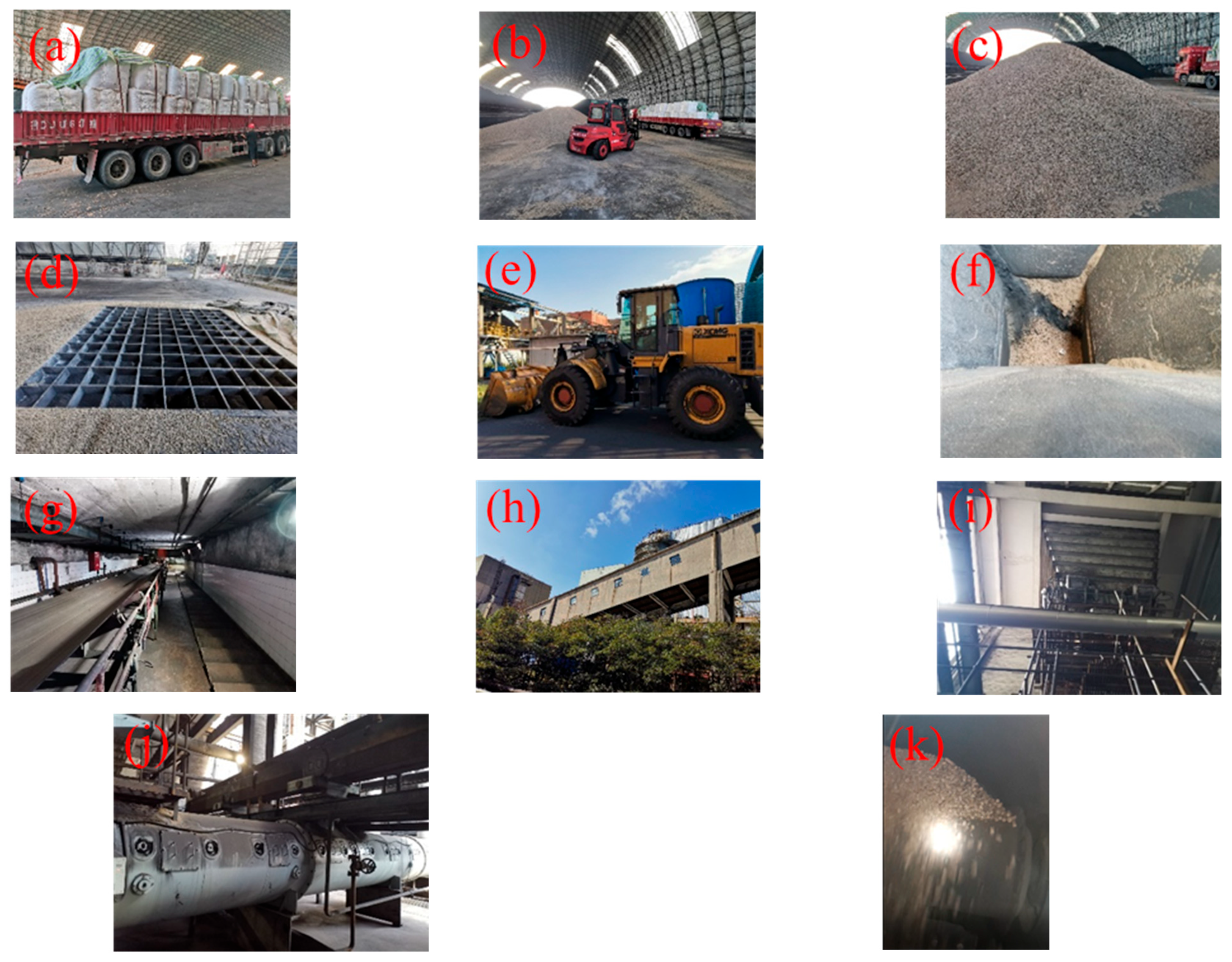
2.1. Experimental Materials

The investigation of the quantities, types, and costs of biomass resources within the economic transportation radius around the project site is critical for the process design when co-firing biomass in a large CFB boiler. Two categories of biomass feedstock are available. Firstly, there is raw biomass that has undergone preliminary crushing. This option involves low costs but involves complex conveying processes, significant quality fluctuations, and high impact on the boiler stability. Secondly, processed densified biomass fuels (such as dried, pulverized, and compressed pellets) can be used. These offer stable quality and easy conveying but come at a higher cost.
This study investigated the resource quantities of agricultural and forestry residues, industrial by-product biomass, and waste wood materials around the project site, as well as the production capacity, output, and expansion potential of the pellet and formed fuel manufacturers. After comprehensively considering factors such as the fuel supply sufficiency, quality stability, limitations on in-plant storage and transportation space, constraints of existing equipment, and delivered costs, compressed biomass pellets were ultimately selected as the co-firing biomass fuel. These pellets are produced by compressing woody raw materials (moisture content: 4–15%) under 60–130 MPa pressure at 70–150 °C, with energy consumption rates of 30–50 kJ/kg. The specifications of the compressed biomass pellets used in this work were as follows: diameter = 8 mm, length = 15–30mm, cylindrical shape, true density = 1.1 t/m3, bulk density = 0.63 t/m3. Their fuel characteristics and ash characteristics are shown in Table 1.
As shown in Table 1, the biomass pellet fuel ash composition contains a relatively high calcium content (25%), reflecting the typical characteristics of woody biomass. However, compared to high-quality woody biomass feedstock, the sulfur (0.14%), nitrogen (2%), and ash (6%) contents are significantly higher, which may be due to the inclusion of recycled wood products, such as old furniture and construction templates, in the feedstock used for compression palletization. Since this study employed low-temperature ash production at 600 °C, the lower temperature retained most of the alkali metal chlorides and a small portion of calcium carbonate in the biomass ash, resulting in a lower ash melting point for the biomass pellet fuel.
Regarding the risks associated with alkali metals (such as ash deposition, slagging, or corrosion) that may be introduced by biomass combustion, this study involved the leaching and testing of the water-soluble Na, K, and Cl in biomass pellets. The results showed that the water-soluble Na content of the biomass pellets was 0.829 mg/g, the water-soluble K content was 0.863 mg/g, and the water-soluble chloride ion content was 2.329 mg/g. Compared to the typical range of 0.5–1.5% found in conventional biomass fuels such as bark, branches, and straw, the alkali metal content of the biomass pellets used in this experiment was relatively low. Therefore, the risk of introducing alkali metals through the co-firing of biomass pellets is relatively low.
Regarding the risks associated with heavy metals that may be introduced by biomass combustion, making fly ash difficult to recycle, this paper conducted microwave digestion and trace analyses of harmful heavy metal components in biomass ash, with the results shown in Table 2. In terms of the elemental contents, all trace elements in the biomass pellet ash were found to be lower than those in common bituminous coal ash. Notably, the 600 °C low-temperature ash-making process was intentionally used to maximize the retention rates of K, Na, and Cl in the ash. This approach also preserved higher fractions of exchangeable and reducible forms of trace heavy metals, which would otherwise volatilize under actual operating temperatures. Therefore, in actual engineering applications, the levels of harmful trace heavy metals in the ash introduced by biomass combustion should be lower than the results of this test.

2.2. Experimental Systems and Methods

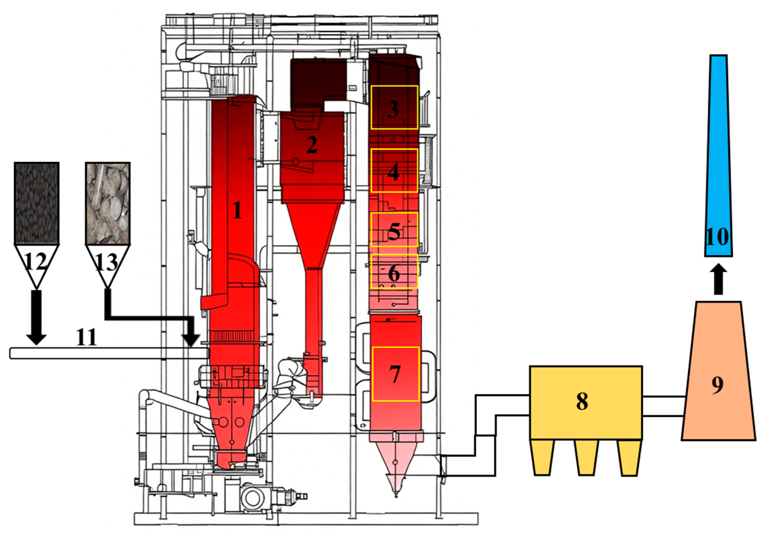
2.2.1. Boiler System

The experiments were conducted on a high-pressure, single-drum, natural-circulation circulating fluidized bed (CFB) boiler without reheating, as shown in Figure 1. The boiler was designed for a blended fuel of coal and petroleum coke (low calorific value: 23.89 MJ/kg; petroleum coke/coal ratio = 3:7). The verification conditions were 100% coal combustion and a coal-to-petroleum coke ratio of 5:5. Table 3 lists the main design parameters of the boiler.
When co-firing biomass (e.g., blending 10 wt% pellets), the fuel’s calorific value (23.20 MJ/kg), although lower than the design value, remains significantly higher than the verified heat value for the 100% coal operation (20.45 MJ/kg). The furnace heat balance can accommodate this. Biomass, characterized by its high volatile content and strong combustion reactivity of its semi-coke, burns out faster than coal or petroleum coke. Under the boiler’s high-efficiency cyclone separation and material circulation system, complete combustion can be ensured. The primary potential impact lies in the significant share of biomass gas-phase combustion and its concentrated heat release in the upper dense phase zone. This may lead to changes in the furnace temperature distribution, which requires experimental verification. Simultaneously, it is essential to ensure that the secondary air system provides sufficient turbulence and penetration capability in the upper dense phase zone to assist in the complete combustion of the substantial volatiles released. This also requires experimental observations and verification.

2.2.2. Feeding System

The existing feed system requires the coal or petroleum coke particles entering the furnace to be <6 mm, necessitating full compatibility with biomass pellets across all processes from the stockyard to the furnace. Field investigations have confirmed that high density, uniform sizing, and excellent flowability of biomass pellets enable stable transportation on existing inclined conveyors, smooth distribution through pants-leg distributors, reliable gravity flow in conical coal silos, and unimpeded passage as a thin layer through the belt feeder’s leveling gate (~25 mm height) without clogging risks. Thus, biomass pellets can integrate into any coal transport stage without compromising the original system integrity.
However, the existing feeding system was equipped with feed-assist and material-disturbing air exceeding 250 °C. If the biomass pellets release volatile components before entering the furnace, the condensed components may form a viscous liquid phase within the piping, posing a risk to the feeding system’s reliability. To prevent this, biomass pellets are blended with coal in the last section of the conveyor belt before the furnace. The mixture leverages coal’s higher thermal capacity to avoid the biomass overheating in the drop leg pipe while minimizing the impacts on the original system’s reliability, uniformity, and stability, ensuring operational continuity for subsequent co-firing tests.
The process flow for biomass fuel reception, storage, transfer, and feeding is illustrated in Figure 2a–h, and is briefly described as follows. The biomass pellets are transported in ton bags, unloaded by forklifts, and stockpiled in the warehouse. Given that biomass pellets are prone to moisture absorption and disintegration upon contact with water, the storage warehouse on site is a covered dry coal shed equipped with a rain canopy, as shown in Figure 2a–c. The biomass pellets are pushed by a loader into the feed bunker, which then fall onto a multi-stage belt conveyor system, as depicted in Figure 2d–f. They are transported via successive belt conveyors to the furnace-front feed bin, as depicted in Figure 2g–i. The blending of the biomass pellets occurs on the last belt of the final-stage belt conveyor system located beside the furnace, as illustrated in Figure 2j,k.

2.2.3. Experimental Design

The purpose of the study is to assess the comprehensive impact of biomass co-firing on the boiler system. This impact includes the heat absorption proportions of various heating surfaces; thermal efficiency of the boiler; furnace fluidization quality and circulation; SOx, NOx, and particulate emissions; ash deposition, slagging, and high-temperature corrosion on high-temperature heating surfaces; ash deposition and dew-point corrosion on low-temperature heating surfaces; denitrification catalyst performance, fly ash reuse; carbon emissions reduction; and technical–economic indicators.
To ensure the safe operation of the boiler, the experiment adopted a method of gradually increasing the biomass mass blending ratio. A preliminary experiment was first conducted. The experiment began with a 100% fossil fuel (coal and petroleum coke, mass ratio of 7:3, calorific value of 23.89 MJ/kg) and gradually increased the biomass mass blending ratio (4.85 wt%, 6.73 wt%, 9.40 wt%). Once the target condition was reached, the main operating parameters of the boiler were recorded, and samples were taken from key parts for an analysis. Based on the successful completion of the preliminary experiment, a formal experiment with a 20 wt% biomass co-firing ratio was conducted following the same procedure. After the formal experiment, the boiler was shut down for maintenance, and observations were made of the ash deposition, slagging, and corrosion in various parts of the boiler, with samples taken for an analysis. Finally, calculations were performed to assess the carbon emissions reductions and technical–economic indicators of biomass co-firing.

2.2.4. Testing Methods

For fuels and ash, this study conducted a proximate analysis (ISO 17246:2024), ultimate analysis (ISO 17247:2020), calorific value determination (ISO 1928:2020), ash composition analysis (GB/T 1574-2007), ash fusion temperature analysis (ISO 540:2023), water-soluble Na/K/Cl content analysis (ASTM D6357), and trace heavy metal content analysis (ISO 23380:2022). The equipment employed included an proximate analyzer (GYFX-610/612), an elemental analyzer (Various EL III), a muffle furnace (AFD1200-40), a calorimeter (ZDHW-8B), an online coal elemental analyzer (Thermo Scientific ECA-3), an ash fusion determinator (AF700SC), an ion chromatograph (ICS900), and an inductively coupled plasma mass spectrometer (NexlON 1000G).
For the deposit ash collected from various boiler sections, X-ray diffraction (XRD), X-ray fluorescence (XRF), and particle size distribution analyses were performed using an X-ray diffractometer (X’Pert PRO MPD), an X-ray fluorescence spectrometer (PANalytical Axios Petro), and a Malvern laser particle size analyzer (MASTER SIZE R3000).
The boiler’s thermal efficiency testing strictly adhered to GB/T 10184-2015. During in-operation instrument sampling, the fly ash flow rates were obtained through grid-based flue gas duct segmentation and isokinetic sampling, utilizing pitot tubes and an isokinetic dust sampler (Laoying 3012H). The flue gas composition was measured via an online flue gas analyzer (Gasmet DX4000).
Industrial circulating fluidized bed (CFB) boilers typically require 8–10 h of operation to achieve a fully developed gas–solid steady state. To ensure the thorough replacement of furnace materials and stable operation, all experiments maintained each target condition for 48 h prior to data acquisition and sampling. It should be noted that the differences among the various testing standards (e.g., GB, ASTM, or ISO) used in this study are minimal and have virtually no impact on the experimental conclusions.

3. Results and Discussion

3.1. The Impact of Low-Ratio Co-Firing (≤10 wt%)

The preliminary experiment lasted for more than a week. During this period, the boiler load remained constant, and no abnormalities were observed in the feeding system, such as biomass slipping on the belt, premature release, or the condensation of biomass volatile matter. This indicates that the biomass pellets are compatible with the feeding system. Table 4 shows the main operating parameters during the preliminary experiment.
As shown in Table 4, under the premise of maintaining a constant boiler load, the co-firing of the biomass pellets led to varying degrees of change in some operating parameters, although overall the impact on the boiler operation was not significant. Specifically, no obvious differences were observed in the carbon contents of fly ash and bottom slag, and the temperatures of the working fluid and flue gas across various heating surfaces remained largely stable. This indicates that the fuel combustion organization and burnout conditions remained good. The heat absorption ratios of the boiler’s heating surfaces and the exhaust gas temperature also remained unchanged. Therefore, a 10 wt% co-firing ratio did not cause any substantial changes in boiler operating conditions.
Firstly, the calorific value range of the biomass was approximately 75–80% of the design fuel’s calorific value. At the same load, as the biomass co-firing ratio increased, the overall calorific value of the fuel mixture entering the furnace gradually decreased. In the preliminary experiments, when the maximum biomass feed rate reached 5 t/h, the total fuel input increased by 1–1.5 t/h compared to the original coal combustion case. Based on boiler efficiency calculations using the input–output method (with the original coal efficiency set as the baseline of 1), the efficiency rates for co-firing 2.53 t/h, 3.65 t/h, and 5.0 t/h of biomass were 1.0076, 0.9979, and 1.0002, respectively. Evidently, within the 10% mass co-firing range, the biomass co-firing had a negligible impact on the boiler’s efficiency.
As the blending ratio of the biomass fuel increased, the average bed temperature in the dense-phase zone showed a slight upward trend, with an increase of approximately 10 °C. This indicates that biomass pellets enhance the heat release share in the dense-phase zone after entering the furnace. Unlike lightweight raw biomass such as straw, densified biomass pellets tend to descend into the dense-phase zone upon entering the furnace, where they are gradually heated and pyrolyzed to release volatiles. Consequently, they reside for longer in the lower furnace section, resulting in a significantly higher proportion of heat release. The stable attemperating water flow further supports this observation; although biomass co-firing may alter the vertical temperature distribution in the furnace, it does not significantly affect the temperature level in the middle-upper furnace or the heat absorption by evaporative heating surfaces. This is advantageous for further increasing the biomass co-firing ratio.
Secondly, the biomass pellets used in the experiment contained recycled wood products, leading to notably higher sulfur, nitrogen, and ash contents compared to high-quality woody biomass feedstock. Thus, gaseous pollutant emissions from co-firing have attracted considerable attention. However, the data in Table 4 show that biomass co-firing reduces NOx emissions, with this trend becoming more pronounced as the blending ratio increases. At a 10% mass blending ratio, the NOx reduction exceeds 35%. This is because during the initial combustion stage, the biomass pyrolyzes, releasing large amounts of reducing volatiles, primarily hydrogen (H2), carbon monoxide (CO), and various hydrocarbons. These gases consume oxygen within localized zones of the furnace, creating a highly reducing (oxygen-deficient) atmosphere. This reducing environment suppresses nitrogen oxide (NOx, mainly NO) formation through two key mechanisms: on the one hand, reducing gases (especially H2, CO, and reactive hydrocarbon radicals) chemically reduce any NO already formed via thermal or prompt mechanisms back into nitrogen gas (N2); on the other hand, this environment alters the conversion pathway of fuel-bound nitrogen. The fuel nitrogen in biomass and coal primarily converts to the intermediate products hydrogen cyanide (HCN) and ammonia (NH3) during pyrolysis. Under oxidizing conditions, HCN and NH3 tend to oxidize to form NO; however, within the reducing atmosphere established by the biomass volatiles, HCN and NH3 are instead more likely to react with existing NO (e.g., NH3 + NO = N2 + H2O) or be directly converted to N2 by reducing species and radicals [26,27,28]. Consequently, the conversion of fuel nitrogen to NOx is significantly diminished. Therefore, a higher biomass blending ratio releases more reducing volatiles, intensifies the reducing atmosphere, and makes this NOx suppression effect more pronounced.
In contrast, the variation in SOx emissions with increasing blending ratios is less distinct. Since the SOx concentrations in flue gas directly correlate with the fuel sulfur content, and biomass pellets have lower sulfur levels with limited blending ratios, their impact on SOx emissions is minimal. The slight rise in SOx emissions observed under specific operating conditions may stem from uncertainties in the sulfur content of recycled wood products used during pellet production.
Moreover, biomass fuel has a far lower ash content than coal. Higher blending ratios, thus, reduce the total ash entering the boiler. As most ash from biomass combustion exits as fly ash, the fluidized particle concentration in the furnace decreases with higher blending ratios. This trend is reflected in the significant drop in primary air plenum pressure shown in Table 4. At low blending ratios, this helps reduce the slag discharge and cold ash extractor operation time, benefiting the boiler operations. However, when the continuous blending increases to the point where the coal ash falls below a critical proportion in the bed material, the fluidization process may deteriorate, reducing the fluidization quality. At this point, given the vital role of circulating material in combustion organization, heat balance, and heat transfer, supplementary heavy bed material must be added externally to maintain normal operations. It is evident that within the 10 wt% blending range, biomass co-firing shows a beneficial effect on the ash balance, fluidization quality, and circulation of the furnace, thereby benefiting the boiler’s operation.
Within the 10 wt% blending range, the biomass co-firing showed no significant impact on the dust emission concentration in the rear flue or the fabric filter differential pressure. However, the frequency of steam soot blowing increased from 2 to 3 times per 24 h, indicating aggravated ash deposition on heating surfaces. Biomass ash, characterized by fine particles, low density, a soft texture, and strong adhesiveness, easily adheres to metal heating surfaces. Nevertheless, with moderate increases in soot blowing frequency, the temperatures across boiler sections and exhaust gas temperatures remain stable, confirming that ash deposition under 10 wt% blending is manageable.
After one week of co-firing experiments, the fouling on heating surfaces intensified. A composition analysis of ash deposits from the high-temperature superheater and horizontal flue (Table 5) revealed significant decreases in silicon, aluminum, and iron, alongside substantial increases in calcium and sulfur. This suggests that the ash from blended biomass exhibits stronger adhesiveness and greater propensity to adhere to heating surfaces. Therefore, caution is warranted when increasing the blending ratios or selecting a biomass with a high alkali metal content. Notably, the alkali metal (K, Na) levels in deposits show no abnormal increases, indicating that ash deposition induced by alkali salt condensation is not the primary mechanism within 10 wt% blending. Alkali metals preferentially combine with sulfur during combustion to form stable sulfates in fly ash, which helps mitigate hazards related to alkali metals and reduce SOx emissions during higher co-firing ratios.

3.2. The Impact of High-Ratio Co-Firing (20 wt%)

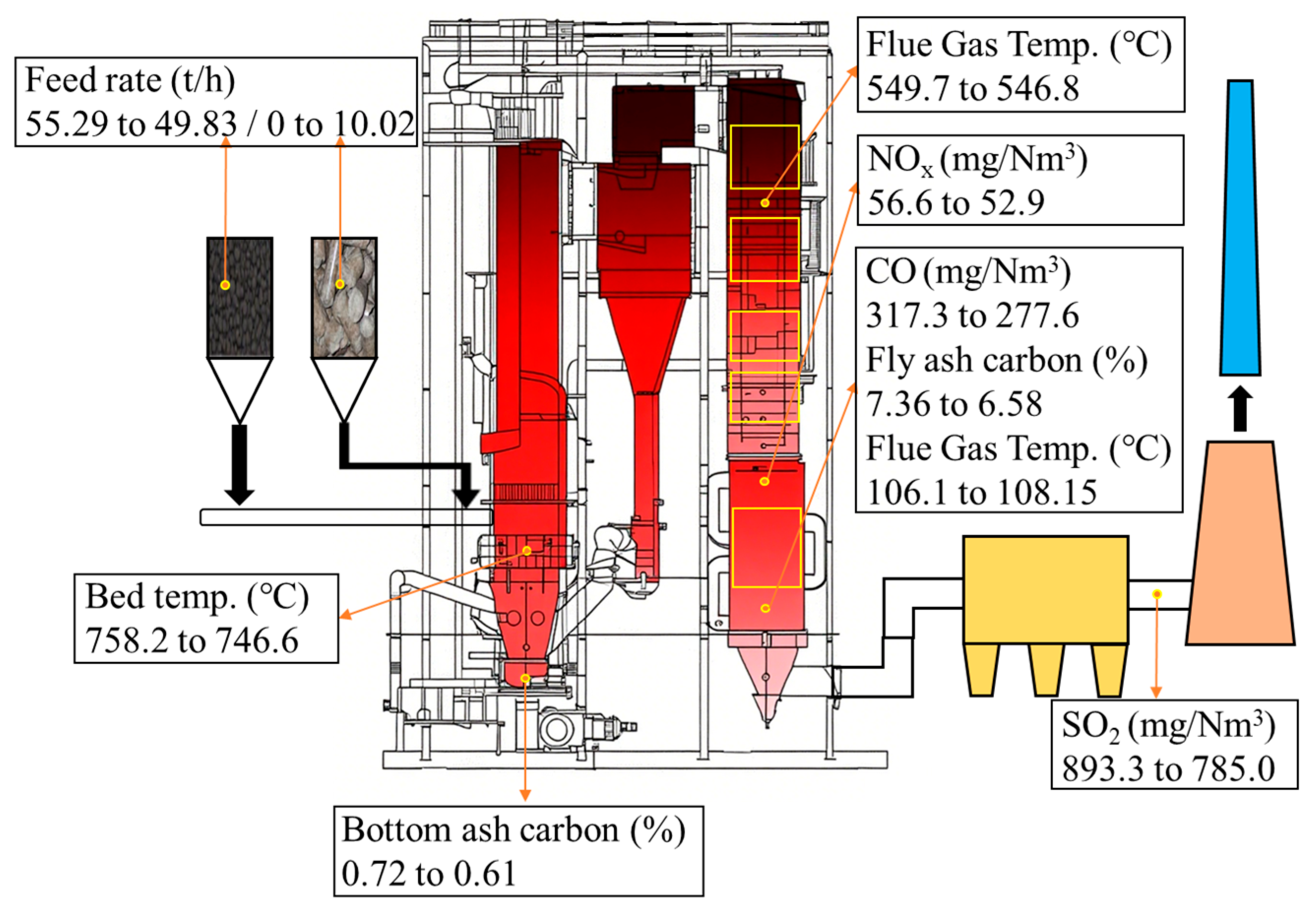
3.2.1. The Impact of Boiler Operating Parameters

In the formal experiment targeting a 20 wt% blending ratio, the fossil fuel used was pure coal. The fundamental combustion characteristics of the coal-biomass blended fuel are shown in Table 6, revealing a calorific value reduction of approximately 700 kJ/kg after biomass blending.
The key boiler operating parameters before and after co-firing are presented in Table 7. During the experiment, the actual mass blending ratio for the target 20 wt% biomass co-firing condition was 16.74%. This actual mass blending ratio was derived from the time-averaged values of each fuel type, measured by the weighing belts at the furnace front under steady-state operating conditions. While the main steam temperature (540 °C) and pressure (9.8 MPa) remained stable, the boiler load decreased from 432.24 t/h to 418.19 t/h (a reduction of ~14 t/h), primarily driven by production-side demand adjustments. Consequently, to compensate for the fuel calorific value reduction (~700 kJ/kg), the total feed rate increased by ~4.6 t/h (from 55.29 t/h to 59.85 t/h). These factors must be considered when comparing the operational parameters between the two conditions.
The variations in boiler operating parameters and efficiency (Figure 3 and Table 7) indicate a ~0.4% improvement in boiler thermal efficiency under 20 wt% co-firing. Accounting for data acquisition errors and sampling heterogeneity, it can be concluded that 20 wt% biomass pellet co-firing has a negligible impact on the boiler’s efficiency.
The exhaust gas heat loss (q2) increased by 0.03%, primarily due to the decreased flue gas velocity (the ratio of co-firing to the original case was 0.94:1), which diminished the convective heat transfer in the rear flue and elevated the exhaust temperature. Meanwhile, the gas incomplete combustion loss (q3) decreased by 0.02% as the CO content dropped from 317.3 mg/Nm3 to 277.6 mg/Nm3 (~40 mg/Nm3 reduction). The solid incomplete combustion loss (q4) declined by 0.43%, with the fly ash carbon content decreasing by ~0.8% and the bottom slag carbon by ~0.1%, demonstrating the biomass’ superior gas and solid burnout efficiency within this blending range. The radiation loss (q5) decreased by 0.02%, attributable to the lower boiler load, while the ash and slag sensible heat loss (q6) remained stable, given the unchanged slag discharge temperature.
Unlike the preliminary experiment, under 20 wt% co-firing, the dense-phase zone’s average bed temperature decreased by ~12 °C. This temperature correlates with the thermocouple placement heights, fluidization velocity, and bed material expansion, and the decrease is more likely linked to the decreased boiler load.
Under high biomass blending ratios (20 wt%), the combustion behavior of fuels in furnaces exhibits no significant changes, primarily due to two factors. The research by Zhang et al. [29] indicates that increasing the diameter of the biomass particles from 0.2 mm to 9.6 mm prolongs the volatile release time from 1.5 s to 40 s. This demonstrates that the larger particle size reduces the volatile release rate per unit mass. Consequently, 8-mm-diameter wood pellets may similarly require several tens of seconds for volatile release, comparable to the volatile release duration of smaller-sized coal particles. Therefore, within coal-fired circulating fluidized bed boilers, the combustion conversion rates of wood pellets (predominantly fueled by volatile release) and coal particles are remarkably similar. On the other hand, the annulus–core structure formed by abundant persistent char particles and bed material particles in the furnace hinders the upward movement of wood pyrolytic semi-coke (with decreased density after volatile release). This confinement causes the wood pellets to undergo heating, pyrolysis, and semi-coke combustion processes at furnace heights essentially identical to those of coal particles. These two factors collectively contribute to similar motion characteristics and combustion conversion rates between wood pellets and coal particles within the furnace. As a result, no significant changes occur in the axial temperature distribution of the furnace or the heat absorption ratios among various heating surfaces. Therefore, compared to other boiler types, coal-fired circulating fluidized bed (CFB) boilers offer significant advantages for co-firing densified wood pellets, with significant potential to further increase their co-firing ratio through optimization of the feeding system and supplementation of the high-density bed material.
Under the 20% co-firing condition, the NOx emissions decreased by ~4 mg/Nm3. Despite a 0.2% increase in blended fuel nitrogen content and 4.6 t/h higher feed rate, the SCR inlet NOx still declined, further verifying that biomass intensifies the reducing atmosphere and suppresses the conversion of nitrogen precursors to NOx. Concurrently, the SO2 emissions dropped significantly by ~108 mg/Nm3, primarily due to the decreased sulfur content in the blended fuel from the biomass, with a secondary contribution from weakly alkaline earth metals in the biomass ash enabling desulfurization through longer residence times and sufficient gas–solid contact during fluidized combustion. Additionally, the primary air plenum pressure decreased by only 0.32 kPa, demonstrating that within the 20 wt% blending range, appropriately reducing the bottom slag discharge according to the coal substitution ratio maintains adequate plenum pressure to ensure good fluidization quality.

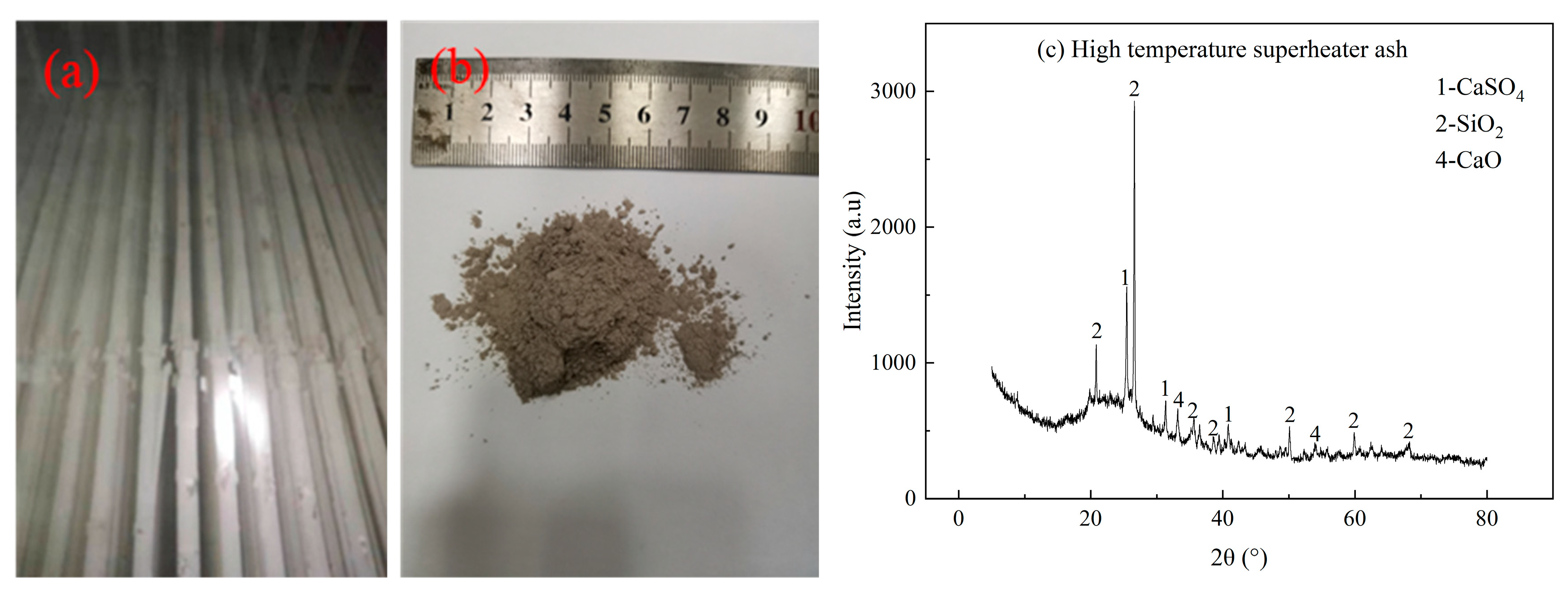
3.2.2. The Effect of the Heating Surface

After completing the 20 wt% biomass co-firing experiment, a boiler shutdown inspection was conducted. Based on visual observations, sampling, and ash sample testing, we systematically evaluated the impacts of biomass co-firing on ash deposition, slagging, and corrosion on both high-temperature and low-temperature heating surfaces of the boiler system. We examined changes in fly ash composition and the effects on the SCR catalyst.
The ash deposition conditions for the high-temperature superheater, low-temperature superheater, high-temperature economizer, low-temperature economizer, and air preheater are shown in Figure 4, Figure 5, Figure 6, Figure 7 and Figure 8. Although powder-like ash deposits were observed on heating surface tube banks, thick accumulations did not form, and no slagging or metal corrosion occurred. Integrated with prior boiler operational data, this indicates that 20 wt% biomass co-firing did not exacerbate the ash deposition, slagging, or corrosion in these areas. The XRD analysis revealed that the primary crystalline phases in the deposits were silica, calcium sulfate, calcium carbonate, and calcium oxide. Despite the high calcium content in the biomass, the 20 wt% blending ratios were insufficient to dominate the deposit composition. Moreover, previous operations under coal-firing conditions employing in-furnace calcium injection desulfurization led to the persistent accumulation of desulfurizing agents and byproducts on rear heating surfaces. Thus, the calcium-bearing substances originated solely from historical coal-firing operations rather than biomass co-firing.
When the flue gas temperature drops below the acid dew point, acidic gases (SO2, SO3, HCl, N2O5) condense on heating surfaces to form corrosive films. Three lines of evidence confirmed that there was no low-temperature corrosion risk in this test. Firstly, no liquid condensate or corrosion marks were found on the air preheater tubes. Secondly, the biomass co-firing decreased the fuel sulfur content from 1.85% to 1.54%, decreasing the SO2 emissions by 108 mg/Nm3 and curtailing the corrosion precursors. Finally, the ash–water solution’s pH reached 10.07 (1g ash + 100mL deionized water, magnetically stirred for 15 min), as biomass-derived alkaline earth metals (K/Na/Ca) formed neutralizing ash layers. Thus, co-firing does not increase the risk of low-temperature corrosion but rather decreases it.
Figure 9 shows slagging in the cyclone separator, with the slag samples extracted from cone and cylinder inner walls exhibiting hard laminar structures, with a thick red sintered layer (Figure 9(b1)) contrasting with a thin pink deposited layer (Figure 9(b2)). Our historical experience from shutdown maintenance operations confirmed that identical slagging patterns occurred without biomass co-firing, thereby eliminating biomass as a contributing factor.
The XRF and XRD analyses (Table 8 and Figure 10) revealed that both layers contained over 1% silicon, aluminum, titanium, calcium, and iron while sharing similar crystalline phases, and the additional presence of iron oxide in the sintered layer was attributable to its distinctive reddish hue. The deposited layer primarily consisted of partially unmelted fine particles (containing SiO2, CaSO4, Al2SiO5) accumulated through layer-by-layer deposition, exhibiting powder-like characteristics. Given that these components have melting points exceeding 1000 °C, the sintered layer formation is likely attributable to localized overheating on inner walls during unstable boiler operation, which was triggered by unburned carbon in the cyclone and subsequently resulted in melting of the fine particles.
This study evaluated risks of ash-deposition-induced blockage, poisoning, and erosion on SCR catalysts through particle size distribution, flue gas flow, and alkali metal (Na/K) content analyses. Figure 11 presents the morphology, particle size distribution, and XRD patterns of SCR catalyst surface ash samples. For vanadium–titanium-based catalysts, the ash blockage mechanisms encompass micropore obstruction (<3.5 nm) and macroscopic “popcorn-like” deposits from particle bridging. The Malvern laser analysis showed a dominant particle size at 30.0 μm with a minimum detection limit of 423 nm (0.432 μm). Although sub-100 nm particles were undetectable, the stable real-time NOx emissions and absence of macroscopic “popcorn-like” deposits confirmed that no blockage occurred.
Alkali metal poisoning involves multi-scale physicochemical processes that disrupt acidic active sites and mass transfer paths. However, the low alkali contents (0.17% Na2O, 0.11% K2O) in the catalyst surface ash and stable NOx emissions indicated no poisoning, despite the ash–water solution showing a pH of 10.92, primarily from the residual calcium-based desulfurizer. Theoretically, biomass co-firing could accelerate catalyst erosion via increased flue gas volumes, although the actual wet flue gas volume decreased by 0.58 Nm3/kg due to the decreased boiler load, thereby mitigating the erosion risk. The catalyst lifespan impact requires long-term operation verification. Collectively, no deactivation phenomena occurred, including ash-bridging blockage, pore obstruction, or alkali-induced crystallization.
The fly ash samples from the baseline and co-firing cases exhibited black coloration, corroborated by the carbon contents (7.36% and 6.58%, Table 7). The XRF results are shown in Table 9. After biomass blending, the fly ash exhibited increases of approximately 1.6% SiO2, 1.8% CaO, and 0.5% SO3. These compositional shifts primarily stemmed from the silicon and calcium enrichment inherent to biomass, with sulfur oxide elevation potentially linked to autogenous desulfurization by alkaline earth metals in biomass.

3.2.3. Carbon Reduction and Technical Economic Indicators

Carbon reduction, techno-economic indicators (power and heat supply), and the boiler heat efficiency under 20 wt% biomass co-firing are shown in Figure 12. Under stable long-term operation with 20 wt% biomass co-firing, the biomass consumption rate reached 10,020 kg/h (LHV 15,939 kJ/kg), displacing 7844 kg/h of coal. Based on the as-received carbon content (52.33%) of the substituted coal, the carbon reduction amounts to 4104 kg/h, equivalent to 130,000 t-CO2/year. At the average carbon market price in China of 42 CNY/t-CO2 during the experiment period, the annual carbon trading revenue is approximately 5.53 million CNY (365 day basis). Furthermore, the government support for biomass power generation includes per-kWh subsidies (calculated as the current feed-in tariff of the project or the local coal-fired power benchmark price), which will deliver additional economic benefits upon the implementation of these policies.
This CFB boiler exhibits a power supply standard coal consumption rate of 288 g/kWh. Given the calorific value of biomass, 1 g of biomass equates to 0.5438 g of standard coal. With biomass fuel priced at ¥1161/t, biomass-derived electricity generation costs 0.6149 CNY/kWh. Assuming full utilization of biomass power at the 0.70 CNY/kWh off-site purchase price, 20 wt% co-firing yields annual savings of 14.10 million CNY.
In the baseline case, the coal consumption rate of 55,290 kg/h resulted in a fuel cost of 53,078 CNY/h (representing 70% of the total costs), which when considering the enthalpy difference between the supply steam and feedwater of 592.64 GJ/h yielded a heat supply cost of 70.4 CNY/GJ. Under 20 wt% co-firing, the increased fuel expenditure of 59,470 CNY/h coupled with a enthalpy difference of 592.40 GJ/h elevated the heat supply cost to 73.6 CNY/GJ, consequently demonstrating that biomass co-firing induces a heat supply cost increment of approximately 3 CNY/GJ.
Biomass co-firing delivers significant carbon reduction benefits (130,000 t/year CO2 reduction and 5.53 million CNY/year carbon revenue) and cost-effective power generation (0.6149 CNY/kWh < external power purchase price). Although the higher biomass energy cost elevates the heat supply expenses, this increment is offset by the carbon trading revenue and power generation subsidies.

4. Conclusions

This study successfully achieved the continuous and stable co-firing of 20 wt% compressed biomass pellets in a large-scale CFB boiler. The key findings are listed below:
1. Stable operation with high potential for increased blending ratios: At this co-firing ratio, the biomass combustion showed no significant adverse effects on the gas- or solid-phase fuel burnout rates or overall thermal efficiency of the boiler. The fluidization status, combustion organization, and distribution of radiative heat absorption in the furnace with convective heat absorption in the rear heating surfaces remained optimal. Due to the densification process of the wood pellets, their size effect (which slows down the rate of volatile release), and the influence of the core–annulus structure formed by coal char particles and bed material particles within the furnace, the motion characteristics and combustion conversion rates of the compressed wood pellets exhibited similarities to coal within the coal-fired CFB furnace. Therefore, compared to other boiler types, coal-fired circulating fluidized bed (CFB) boilers offer significant advantages for co-firing densified wood pellets, with significant potential to further increase their co-firing ratio through the optimization of the feeding system and supplementation of high-density bed materials.
2. Notable environmental and operational benefits: The co-firing delivered multiple advantages: (a) significant reductions in SOx and NOx emissions; (b) decreased bottom ash discharge rates; (c) it mitigated the low-temperature corrosion risks in the rear heating surfaces; (d) annual CO2 reductions of ~130,000 tons, advancing the low-carbon transition.
3. Controllable ash deposition and corrosion: Despite inherent alkali metal challenges in biomass, no evident increase in heating surface fouling, slagging propensity, or corrosion rates was observed when using compressed wood pellets at 20 wt% co-firing. The enhanced ash adhesion characteristics noted during the experiments were effectively managed by increasing the soot-blowing frequency.

Author Contributions

Writing—original draft preparation, visualization, validation, investigation, H.Z.; writing—review and editing, conceptualization, supervision, funding acquisition, resources, C.Y. All authors have read and agreed to the published version of the manuscript.

Funding

This work was supported by the National Key Technologies Research and Development Program of China (Grant No. 2022YFB4202002).

Data Availability Statement

Dataset available on request from the authors. The raw data supporting the conclusions of this article will be made available by the authors on request.

Conflicts of Interest

The authors declare no conflicts of interest. The funders had no role in the design of the study; in the collection, analyses, or interpretation of data; in the writing of the manuscript; or in the decision to publish the results.

Abbreviations

The following abbreviations are used in this manuscript:
CFBCirculating Fluidized Bed
PCPulverized Coal
wt%Weight Percent (mass fraction)
LHVLow Heat Value
XRDX-Ray Diffraction
XRFX-Ray Fluorescence
ECREconomic Continuous Rating
BMCRBoiler Maximum Continuous Rating
APHAir Preheater
SCRSelective Catalytic Reduction
CNYChinese Yuan
DTDeformation Temperature
STSoftening Temperature
HTHemisphere Temperature
FTFlow Temperature

References

  1. Peng, B.; Zhao, Y.; Elahi, E.; Wan, A. Can third-party market cooperation solve the dilemma of emissions reduction? A case study of energy investment project conflict analysis in the context of carbon neutrality. Energy 2023, 264, 126280. [Google Scholar] [CrossRef]
  2. Kongkuah, M.; Alessa, N. Renewable Energy and Carbon Intensity: Global Evidence from 184 Countries (2000–2020). Energies 2025, 18, 3236. [Google Scholar] [CrossRef]
  3. Zhou, X.; Zhu, Q.; Xu, L.; Wang, K.; Yin, X.; Mangla, S.K. The effect of carbon tariffs and the associated coping strategies: A global supply chain perspective. Omega 2024, 122, 102960. [Google Scholar] [CrossRef]
  4. Xu, Y.; Wang, H.; Liu, X.; Zhu, J.; Xu, J.; Xu, M. Mitigating CO2 emission in pulverized coal-fired power plant via co-firing ammonia: A simulation study of flue gas streams and exergy efficiency. Energy Convers. Manag. 2022, 256, 115328. [Google Scholar] [CrossRef]
  5. Yan, S.; Lv, C.; Yao, L. Social welfare and equality equilibrium based carbon tax subsidy incentive approach for biomass-coal co-firing towards carbon emissions. Energy 2024, 291, 130282. [Google Scholar] [CrossRef]
  6. Zheng, J.; Cai, C.; Ge, T.; Zhang, M. Effect of Potassium on the Co-Combustion Process of Coal Slime and Corn Stover. Energies 2024, 17, 5185. [Google Scholar] [CrossRef]
  7. Cho, K.; Lee, Y. Life Cycle Assessment of Torrefied Residual Biomass Co-Firing in Coal-Fired Power Plants: Aspects of Carbon Dioxide Emission. Energies 2024, 17, 6165. [Google Scholar] [CrossRef]
  8. Peters, J.; May, J.; Ströhle, J.; Epple, B. Flexibility of CFB Combustion: An Investigation of Co-Combustion with Biomass and RDF at Part Load in Pilot Scale. Energies 2020, 13, 4665. [Google Scholar] [CrossRef]
  9. Kim, D.-W.; Park, K.; Lee, G.-H.; Lee, J.-M.; Hwang, J. Optimal blending ratio of Elga caking coal in Samcheok circulating fluidized bed boilers: Experimental and practical insights. Fuel 2025, 386, 134235. [Google Scholar] [CrossRef]
  10. Xie, J.-j.; Yang, X.-m.; Zhang, L.; Ding, T.-l.; Song, W.-l.; Lin, W.-g. Emissions of SO2, NO and N2O in a circulating fluidized bed combustor during co-firing coal and biomass. J. Environ. Sci. 2007, 19, 109–116. [Google Scholar] [CrossRef] [PubMed]
  11. Quan, S.; Zeng, Y.; Wu, Y.; Kim, R.-G.; Li, Z.; Han, Y.; Li, J.; Jeon, C.-h.; Zhu, X.; Wang, H.; et al. Ash thermomechanical properties and combustion characteristics during Co-combustion of anthracite and biomass for CFB combustors. Biomass Bioenergy 2025, 198, 107868. [Google Scholar] [CrossRef]
  12. Unchaisri, T.; Fukuda, S. Investigation of ash formation and deposit characteristics in CFB co-combustion of coal with various biomass fuels. J. Energy Inst. 2022, 105, 42–52. [Google Scholar] [CrossRef]
  13. Krzywanski, J.; Rajczyk, R.; Bednarek, M.; Wesolowska, M.; Nowak, W. Gas emissions from a large scale circulating fluidized bed boilers burning lignite and biomass. Fuel Process. Technol. 2013, 116, 27–34. [Google Scholar] [CrossRef]
  14. Gungor, A. Simulation of co-firing coal and biomass in circulating fluidized beds. Energy Convers. Manag. 2013, 65, 574–579. [Google Scholar] [CrossRef]
  15. Wan, H.-P.; Chang, Y.-H.; Chien, W.-C.; Lee, H.-T.; Huang, C.C. Emissions during co-firing of RDF-5 with bituminous coal, paper sludge and waste tires in a commercial circulating fluidized bed co-generation boiler. Fuel 2008, 87, 761–767. [Google Scholar] [CrossRef]
  16. Chen, T.; Zhao, Y.; Huang, S.; Jin, Y.; Wang, M.; Feng, H.; Yin, J. Influence of papermaking biomass co-firing on operation energy efficiency and gas emission stability of a coal-fired thermal power plant: A case study. Energy 2025, 327, 136484. [Google Scholar] [CrossRef]
  17. Liu, X.; Teng, Y.; Zhang, K. Migration Behaviors of As, Se and Pb in Ultra-Low-Emission Coal-Fired Units and Effect of Co-Firing Sewage Sludge in CFB Boilers. Energies 2022, 15, 1544. [Google Scholar] [CrossRef]
  18. Tzelepi, V.; Zeneli, M.; Kourkoumpas, D.-S.; Karampinis, E.; Gypakis, A.; Nikolopoulos, N.; Grammelis, P. Biomass Availability in Europe as an Alternative Fuel for Full Conversion of Lignite Power Plants: A Critical Review. Energies 2020, 13, 3390. [Google Scholar] [CrossRef]
  19. Chen, A.; Liu, Y. Optimizing sustainable biomass–coal co-firing power plant location problem under ambiguous supply. Comput. Ind. Eng. 2023, 182, 109401. [Google Scholar] [CrossRef]
  20. Smith, J.S.; Safferman, S.I.; Saffron, C.M. Development and application of a decision support tool for biomass co-firing in existing coal-fired power plants. J. Clean. Prod. 2019, 236, 117375. [Google Scholar] [CrossRef]
  21. Dumortier, J. Co-firing in coal power plants and its impact on biomass feedstock availability. Energy Policy 2013, 60, 396–405. [Google Scholar] [CrossRef]
  22. Zhang, Y.-L.; Liu, L.-C.; Kang, J.-N.; Peng, S.; Mi, Z.; Liao, H.; Wei, Y.-M. Economic feasibility assessment of coal-biomass co-firing power generation technology. Energy 2024, 296, 131092. [Google Scholar] [CrossRef]
  23. Zhang, X.; Ghamari, M.; Ratner, A. Numerical modeling of co-firing a light density biomass, oat (Avena sativa) hulls, and chunk coal in fluidized bed boiler. Biomass Bioenergy 2013, 56, 239–246. [Google Scholar] [CrossRef]
  24. Fan, X.; Yang, L.; Jiang, J. Experimental study on industrial-scale CFB biomass gasification. Renew. Energy 2020, 158, 32–36. [Google Scholar] [CrossRef]
  25. Chen, X.; Zhang, C.; Chen, X.; Peng, Z.; Gao, H.; Gong, X. Performance analysis of a novel biomass gasification system coupled to a coal-fired power plant based on heat and water recovery. Energy Convers. Manag. 2024, 299, 117822. [Google Scholar] [CrossRef]
  26. Wang, X.; Luo, Z.; Wang, Y.; Zhu, P.; Wang, S.; Wang, K.; Yu, C. NO emission during the co-combustion of biomass and coal at high temperature: An experimental and numerical study. J. Energy Inst. 2024, 115, 101707. [Google Scholar] [CrossRef]
  27. Allgurén, T.; Andersson, K.; Fry, A.; Eddings, E.G. NO formation during co-combustion of coal with two thermally treated biomasses. Fuel Process. Technol. 2022, 235, 107365. [Google Scholar] [CrossRef]
  28. Wang, X.; Zhang, J.; Xu, X.; Mikulčić, H.; Li, Y.; Zhou, Y.; Tan, H. Numerical study of biomass Co-firing under Oxy-MILD mode. Renew. Energy 2020, 146, 2566–2576. [Google Scholar] [CrossRef]
  29. Zhang, J.; Wang, Z.; Dai, G.; Heberlein, S.; Chan, W.P.; Wang, X.; Tan, H.; Lisak, G. Assessing the effect of size and shape factors on the devolatilization of biomass particles by coupling a rapid-solving thermal-thick model. J. Anal. Appl. Pyrolysis 2024, 183, 106835. [Google Scholar] [CrossRef]
Figure 1. Boiler system schematic diagram: (1) furnace; (2) cyclone separator; (3) high-temperature superheater; (4) low-temperature superheater; (5) high-temperature economizer; (6) low-temperature economizer; (7) air preheater; (8) fabric filter; (9) absorption tower; (10) chimney; (11) belt conveyor system; (12) coal bunker; (13) biomass bunker.
Energies 18 03832 g001
Figure 2. On-site schematic diagram of biomass fuel feeding system: (a) Ton bag transport; (b) Forklift unloading; (c) Storage in warehouse; (d) Ground-level feed inlet; (e) Pushing loader; (f) Beneath the Feed Inlet; (g) Lead conveyor belt under feed inlet; (h) Transfer via conveyor belt system; (i) Furnace-front biomass feed bin; (j) Final-stage conveyor system beside furnace; (k) Blended biomass pellets falling into feed pipe.
Energies 18 03832 g002
Figure 3. Schematic diagram of key boiler parameter variations.
Energies 18 03832 g003
Figure 4. Ash deposition in the high-temperature superheater: (a) ash deposition photo; (b) ash sample; (c) XRD result.
Energies 18 03832 g004
Figure 5. Ash deposition in the low-temperature superheater: (a) ash deposition photo; (b) ash sample; (c) XRD result.
Energies 18 03832 g005
Figure 6. Ash deposition in the high-temperature economizer: (a) ash deposition photo; (b) ash sample; (c) XRD result.
Energies 18 03832 g006
Figure 7. Ash deposition in the low-temperature economizer: (a) ash deposition photo; (b) ash sample; (c) XRD result.
Energies 18 03832 g007
Figure 8. Ash deposition in the air preheater: (a) ash deposition photo; (b) ash sample; (c) XRD result.
Energies 18 03832 g008
Figure 9. Ash slagging in the cyclone separator: (a) ash slagging photo; (b1b3) slag sample.
Energies 18 03832 g009
Figure 10. XRD results of slag sample in the cyclone separator: (a) XRD result of sintered layer; (b) XRD result of deposited layer.
Energies 18 03832 g010
Figure 11. Ash deposition on SCR catalyst surface and ash particle size distribution: (a) ash sample; (b) ash particle size distribution; (c) XRD result.
Energies 18 03832 g011
Figure 12. Carbon reduction, techno-economic indicators, and boiler efficiency under 20 wt% biomass co-firing.
Energies 18 03832 g012
Table 1. Fundamental combustion characteristics of biomass fuels.
Calorific ValueAsh Composition
Qar.net (MJ/kg)15.94SiO2 (%)31.87
Proximate analysisAl2O3 (%)4.89
Mar (%)7.40Fe2O3 (%)3.60
Aar (%)6.39CaO (%)25.42
FCar (%)15.7MgO (%)5.98
Var (%)70.51K2O (%)5.47
Elemental analysisNa2O (%)2.66
Car (%)42.16TiO2 (%)0.74
Har (%)4.63SO3 (%)8.70
Oar (%)37.01P2O5 (%)10.17
Nar (%)2.27
Sar (%)0.14
Ash fusion temperature
DT (°C)ST (°C)HT (°C)FT (°C)
1150120112101218
Table 2. A trace analysis of harmful heavy metals in biomass ash.
As (mg/kg)Cd (mg/kg)Cr (mg/kg)Cu (mg/kg)Pt (mg/kg)Hg (mg/kg)Ni (mg/kg)Zn (mg/kg)
3.270.9626.359.8644.550.424.68163.16
Table 3. Key design parameters of the boiler.
ParameterUnitDesign Value
Rated evaporation capacity (ECR)t/h571
Maximum evaporation (BMCR)t/h620
Steam drum operating pressureMPa10.84
Steam drum design pressureMPa11.50
Main steam pressureMPa9.81
Main steam temperature°C540
Feedwater temperature°C223 (BMCR)
215 (ECR)
Economizer outlet water temp.°C310
Primary air outlet temp. (APH)°C285
Secondary air outlet temp. (APH)°C280
Flue gas temperature°C135
Boiler efficiency%92.36
Dust concentration (APH outlet)g/Nm331.35
Flue gas flow (APH outlet)Nm3/h537,899
SO2 emission concentration (APH outlet)mg/Nm3400
NOx emission concentration (APH outlet)mg/Nm3150
Ca/S molar ratio (at 90% desulfurization)/2.8
Bottom ash to fly ash ratio/40%:60%
Table 4. Key boiler operating parameters.
ParameterBaseline Case
(70% Coal + 30% Petroleum Coke)
Co-Firing Case
(5 wt% Biomass)
Co-Firing Case
(7 wt% Biomass)
Co-Firing Case
(10 wt% Biomass)
Actual blending ratio0%4.85%6.73%9.40%
Boiler load (%)370370370370
Biomass fuel feed rate (t/h)02.533.565.0
Total fuel feed rate (t/h)51.7552.152.953.2
Average bed temperature (°C)865.5868.2873.3875.6
Attemperating water flow (t/h)5.38/0.19/0.435.0/0.12/0.174.49/0.13/0.435.52/0.4/0.63
SCR inlet NOx (mg/Nm3)53.1/25.653.7/20.152.2/19.733.2/17.8
High-temp. superheater outlet gas temp. (°C)519.1/515.1516.3/513.7518.0/514.3522.8/520.0
High-temp economizer outlet gas temp. (°C)345.2/347.5344.7/347.1345.0/346.1345.8/348.3
Exhaust gas temperature (°C)99.3/114.797.7/113.599.7/115.4100.5/116.6
Primary air plenum pressure (kPa)13.8913.7813.0113.21
Absorption tower inlet/outlet SO2 (mg/Nm3)2776.6/4.962727.7/4.852864.3/5.52729.5/5.38
Fabric filter differential pressure (Pa)593/989.6599.2/965.5600.6/965.8597.8/988
Absorption tower inlet/outlet dust (mg/Nm3)1.71/0.291.46/0.291.77/0.291.67/0.292
Table 5. Ash compositions from a high-temperature superheater, horizontal flue, and designed fuel (%).
SiO2Al2O3Fe2O3CaOMgOK2ONa2OSO3Others
High-temp. superheater ash 30.8625.053.9715.422.920.710.179.129.62
Horizontal flue ash38.4730.924.264.092.601.860.253.2011.93
Designed fuel ash48.9734.877.192.460.680.830.221.932.90
Table 6. Fundamental characteristics of fuels before and after blending.
Car
%
Har
%
Oar
%
Nar
%
Sar
%
Mar
%
Aar
%
Var
%
FCar
%
Qnet,ar(kJ/kg)
Coal52.334.119.260.941.854.3027.2025.2043.3020,360.00
Mixed fuel49.764.1313.751.151.546.3923.2732.3737.9719,619.84
Table 7. Detailed operating parameters and boiler efficiency.
Baseline Case (100% Coal)Co-Firing Case (20 wt% Biomass)
Actual blending ratio016.74%
Boiler load (t/h)432.24418.19
Steam temperature (°C)540540
Steam pressure (MPa)9.89.8
Biomass fuel feed rate (t/h)010.02
Total fuel feed rate (t/h)55.2959.85
Average bed temperature (°C)758.2746.6
Attemperating water flow (t/h)1.19/0.00/0.001.09/0.00/0.00
SCR inlet NOx (mg/Nm3)56.652.9
High temp. superheater outlet gas temp. (°C)536.4/563.0531.2/562.3
Exhaust gas temperature (°C)98.0/114.299.9/116.4
Primary air plenum pressure(kPa)14.96/14.72/8.2714.90/14.71/8.02
Absorption tower inlet/outlet SO2 (mg/Nm3)893.3/1.7785.0/1.3
Bottom ash flow rate (t/h)5.044.16
Fly ash carbon content (%)7.366.58
Bottom ash carbon content (%)0.720.61
Actual wet flue gas flow rate (Nm3/kg)6.946.78
Exhaust gas heat loss (q2, %)5.185.21
Gas incomplete combustion loss (q3, %)0.090.07
Solid incomplete combustion loss (q4, %)2.432.00
Radiation loss (q5, %)0.690.71
Ash/Slag sensible heat loss (q6, %)0.010.01
Boiler efficiency (%)91.6092.01
Table 8. XRF results of slag sample in the cyclone separator (%).
SiO2Al2O3TiO2CaOFe2O3K2OSO3MgOP2O5Na2OBaOOthers
Sintered layer37.432.32.362.222.070.9020.5800.4010.3430.1240.08121.22
SiO2Al2O3TiO2Fe2O3CaOK2OZrO2BaOMgOP2O5SO3Others
Deposited layer31.928.63.672.962.510.6650.6480.4780.3670.2760.21327.71
Table 9. XRF results of fly ash in baseline case and co-firing case (%).
SiO2Al2O3TiO2Fe2O3CaOMgOK2OSO3P2O5
Baseline case (100% coal)37.431.11.652.462.90.290.561.730.18
Co-firing case (20 wt% biomass)39.030.61.732.933.760.510.692.180.27
Disclaimer/Publisher’s Note: The statements, opinions and data contained in all publications are solely those of the individual author(s) and contributor(s) and not of MDPI and/or the editor(s). MDPI and/or the editor(s) disclaim responsibility for any injury to people or property resulting from any ideas, methods, instructions or products referred to in the content.

