Review

A Review of Electromagnetic Wind Energy Harvesters Based on Flow-Induced Vibrations

by
Yidan Zhang
1,
Shen Li
1,
Weilong Wang
1,
Pengfei Zen
2,
Chunlong Li
2,
Yizhou Ye
1,* and
Xuefeng He
1,*
1
College of Optoelectronic Engineering, Chongqing University, Chongqing 400044, China
2
State Grid Smart Grid Research Institute Co., Ltd., Beijing 102209, China
*
Authors to whom correspondence should be addressed.
Energies 2025, 18(14), 3835; https://doi.org/10.3390/en18143835
Submission received: 4 June 2025 / Revised: 3 July 2025 / Accepted: 17 July 2025 / Published: 18 July 2025

Abstract

The urgent demand of wireless sensor nodes for long-life and maintenance-free miniature electrical sources with output power ranging from microwatts to milliwatts has accelerated the development of energy harvesting technologies. For the abundant and renewable nature of wind in environments, flow-induced vibration (FIV)-based wind energy harvesting has emerged as a promising approach. Electromagnetic FIV wind energy harvesters (WEHs) show great potential for realistic applications due to their excellent durability and stability. However, electromagnetic WEHs remain less studied than piezoelectric WEHs, with few dedicated review articles available. This review analyzes the working principle, device structure, and performance characteristics of electromagnetic WEHs based on vortex-induced vibration, galloping, flutter, wake galloping vibration, and Helmholtz resonator. The methods to improve the output power, broaden the operational wind speed range, broaden the operational wind direction range, and enhance the durability are then discussed, providing some suggestions for the development of high-performance electromagnetic FIV WEHs.

1. Introduction

Wireless sensor network technology has broad application prospects in fields such as smart cities, environmental monitoring, and structural health monitoring [1,2]. More and more wireless sensor nodes are being and will be deployed in the surroundings. Currently, the majority of wireless sensor nodes are powered by traditional chemical batteries. Replacing or charging these batteries requires a significant amount of manpower and financial resources, and in addition, the large-scale deployment of battery-powered wireless sensor nodes causes serious environmental pollution [3]. Energy harvesting technology has been proposed to solve these issues by converting the ambient unused energies (such as solar energy [4], thermal energy [5], vibration energy [6], wind energy [7], etc.) into electrical energy to power wireless sensor nodes. Due to the wind energy being a widely distributed green and renewable energy source, miniature wind energy harvesters (WEHs) with the output power ranging from microwatts to milliwatts attract increasing attention as the power sources of wireless sensor nodes.
The utilization of wind energy dates back to the invention of windmills, originally used for mechanical tasks. In 1891, Denmark’s Poul la Cour designed the first modern wind turbine for power generation; in the 1970s, France’s Georges Darrieus invented the vertical-axis turbine; and Hermann Betz’s turbine theory further improved the efficiency of horizontal-axis wind turbines [8,9,10]. As the traditional energy sources such as oil and coal are increasingly depleted, renewable energy sources like wind energy have gained attention for their environmental benefits [11,12]. By 2024, global wind power generation accounted for approximately 12% to 15% of the total energy production [13]. According to the mechanism of converting the wind into kinetic energy, the miniature WEHs can be divided into two types: wind turbines and WEHs based on flow-induced vibrations (FIVs). The wind turbines convert wind energy into rotational kinetic energy of the blades through the Bernoulli effect, while the FIV WEHs harness FIV phenomena such as vortex-induced vibration (VIV) [14], galloping [15], flutter [16], and wake galloping [17] to convert wind energy into vibration energy, and then the rotational kinetic energy or the vibration energy is transformed into electrical energy through electromechanical transduction mechanisms like the piezoelectric effect [18], electromagnetic induction [19], and triboelectric effect [20]. Miniature wind turbines have lower efficiency in low-wind-speed conditions, more complex mechanical structures, increased risk of failure, and generally higher manufacturing costs. In contrast, miniature FIV WEHs can operate at lower wind speeds, have simpler structures, lower maintenance requirements, and better economic efficiency, thus compensating for some of the limitations of wind turbines. The miniature wind turbines and FIV WEHs can be used to directly collect ambient wind energy. In addition, by fixing traditional miniature vibration energy harvesters on FIV structures (such as a tree and a long-span bridge), the wind energy can also be indirectly converted into electrical energy. This review primarily focuses on FIV WEHs, and therefore, unless otherwise specified, WEHs mentioned hereinafter refer to FIV WEHs.
Piezoelectric WEHs can only generate high output power when the piezoelectric material is subjected to alternating large strain, but long-term alternating large strain would lead to fatigue damage [21,22]. The surfaces of triboelectric WEHs are prone to damage during long-term service, leading to a decrease in their output performances [23,24]. The main components of electromagnetic WEHs for electromechanical conversion are magnets and metal coils. Compared with piezoelectric and triboelectric WEHs, electromagnetic WEHs generally have higher cut-in wind speeds due to the relatively larger mass of moving components, and larger overall volumes due to the relatively larger volume of magnets and coils. The durability and long-term stability of magnets and coils have been verified in large-scale turbines. Therefore, electromagnetic WEHs have better durability and stability than piezoelectric and triboelectric WEHs. The superior durability and stability of electromagnetic WEHs make them feasible to power wireless sensor nodes that require long-term service. Even though there are review articles specifically focusing on piezoelectric WEHs or triboelectric WEHs, there are few review papers dedicated solely to electromagnetic WEHs. This review summarizes the recent advances in electromagnetic FIV WEHs, based on the peer-reviewed articles published in English journals. In Section 2, the working principles, structural configurations, and performance characteristics of electromagnetic WEHs based on vortex-induced vibration, galloping, flutter, wake galloping, and Helmholtz resonance are introduced. Section 3 reviews various strategies for improving energy conversion performance. In Section 4, key challenges related to environmental adaptability, durability, and system integration under real-world conditions are examined. Finally, Section 5 summarizes the main conclusions and outlines future research directions.

2. Electromagnetic Wind Energy Harvesters Based on Different FIV Phenomena

FIVs are generally categorized into two primary types based on their excitation mechanism: forced vibration and self-excited vibration. Forced FIV arises from the direct influence of periodic external aerodynamic forces acting on the structure. In this case, it is commonly understood that the vibration frequency is primarily dictated by the frequency of the external forcing—typically associated with wind speed—rather than by the structural natural frequency. As the wind speed varies, so do the frequency and amplitude of the aerodynamic loads, resulting in a wind-speed-dependent vibration response. Vortex-induced vibration (VIV) and wake-induced galloping are often cited as representative forms of forced FIV [25,26,27,28]. Self-excited FIV is initiated through the dynamic coupling between the structural motion and the surrounding aerodynamic forces. This mechanism involves a positive feedback loop: structural displacement induces changes in aerodynamic loading, which, in turn, reinforces and amplifies the vibration. It is widely recognized that the frequency of self-excited FIV tends to align with the natural frequency of the structure, and its amplitude increases progressively with wind speed. If unmitigated, such amplification can lead to dynamic instability or structural failure. Flutter and galloping serve as classic examples of self-excited FIV phenomena [29,30,31].

2.1. Based on Vortex-Induced Vibration

When air flows through a structure such as a cylinder, the vortices are formed alternately on both sides of the structure, which in turn generate periodic vortex shedding downstream. These vortices exert a transverse aerodynamic force on the structure, which triggers periodic vibrations. The frequency of VIV is related to a number of factors, including wind speed, the size of the structure, and its shape. For cylinders that can vibrate freely, a synchronization or locking phenomenon can be observed [32]: at wind speed, the frequency of vortex shedding is the same as the natural shedding frequency of a stationary cylinder, and this frequency is determined by the Strouhal number. However, as the wind speed increases, the vortex shedding frequency approaches the inherent frequency of the cylinder. In a wind speed range, the vortex shedding frequency no longer follows the original relationship of the Strauer number, but is “locked” to the inherent frequency of the cylinder. When the vortex shedding frequency is close to the intrinsic frequency of the cylinder, a significant vibration amplitude is usually observed in the locking interval, which manifests itself as a near-resonance phenomenon. If the vibration frequency matches the intrinsic frequency of the cylinder, resonance occurs, resulting in a significant increase in amplitude. The frequency of vortex excitation shedding can be expressed as
f = S t U D
where f is the vortex shedding frequency, U is the wind speed, D is the characteristic diameter of the structure, and S t is the Strouhal number, which gives the relationship between the vortex shedding frequency and the wind speed.
The dynamic response patterns of vortex-induced vibration (VIV) have been extensively explored through experimental investigations. Feng et al. [33] demonstrated that resonance in a vibrating cylinder occurs at a critical reduced velocity, and they established corresponding nondimensional parameters to describe the phenomenon. Under low mass ratio conditions, the VIV response has been widely categorized into the initial excitation stage, the lower branch, and the upper branch, each associated with distinct wake modes—namely, “2S” (two single vortices) and “2P” (two vortex pairs), respectively. In further work, Jeon and Gharib [34] analyzed wake vortex structures induced by forced vibrations with one and two degrees of freedom. It was found that in-line vibration effectively suppresses the emergence of the “2P” wake mode. Additionally, Jauvtis and Williamson [35] identified a novel VIV response regime referred to as the “super upper branch,” thereby extending the recognized classifications of VIV dynamics.
Recent studies have demonstrated that through careful manipulation of bluff body geometries, structural configurations, and transduction mechanisms, the performance of VIV WEHs can be significantly enhanced across a range of flow conditions. An aeroelastic configuration utilizing an airfoil mounted on a cantilever beam exemplifies how lift modulation can be exploited to induce VIV. In this setup, as described by Zhu et al. [36], the interaction between airflow and the airfoil generates bending in the cantilever. A downstream bluff body reduces lift by disturbing the flow, prompting the beam to rebound. This cyclic deformation produces relative motion between an embedded magnet and surrounding coils, thereby inducing voltage via Faraday’s law. The system demonstrated a low cut-in wind speed of 2.5 m/s with a power output of 470 μW, increasing to 1.6 mW at 5 m/s, highlighting the effectiveness of mechanically resonant systems for energy harvesting in low-speed environments.
Vortex shedding from bluff bodies has also been leveraged to directly stimulate electromagnetic transducers. One notable implementation involves a trapezoidal bluff body placed within a flow channel, coupled to a PDMS diaphragm that transmits oscillatory pressure to a suspended magnet. In this context, Wang et al. [37] demonstrated that the diaphragm facilitates vertical magnet displacement relative to a fixed coil, generating a peak-to-peak voltage of approximately 20 mV under periodic pressure excitation (~0.3 kPa at 62 Hz). This design illustrates how flexible membrane structures can enhance energy transfer efficiency from fluid to electromagnetic domains within VIV regimes.
To enable optimization of VIV-based harvesters, Xu et al. [38] introduced a theoretical framework capturing the coupled dynamics between a cylindrical resonator undergoing VIV and a linear translational electromagnetic generator. The model is based on a dual-mass representation accounting for the relative motions of the generator stator and translator. Analytical results derived from this formulation provide scaling laws for mechanical–electrical conversion and suggest a maximum efficiency of up to 8% under resonant conditions, offering practical insights for mass tuning and structural design.
Flexibility in the energy-harvesting structure itself has also been explored as a means of enhancing VIV-induced performance. Atrah et al. [39] utilized a flexible windbelt actuated by periodic pressure fluctuations originating from a Kármán vortex street. The resulting deformation of the windbelt causes an embedded magnet to oscillate within a surrounding coil, generating electricity. Experimental observations emphasized that energy conversion is strongly dependent on bluff body placement and geometry, with peak efficiency achieved when a 3 cm diameter cylindrical barrier was positioned 10 cm upstream—effectively synchronizing the vortex shedding frequency with the structural resonance of the windbelt.
In more complex systems, the integration of nonlinear dynamic elements has proven effective in broadening the operational range of VIV harvesters. A representative example is the two-degree-of-freedom harvester introduced by Huang et al. [40], which combines a hollow cylindrical structure subjected to asymmetric vortex shedding with a bistable vibration absorber. The nonlinear restoring force introduced by the bistable mechanism enhances the system’s responsiveness to varying flow velocities, enabling sustained energy output. Moreover, the design takes advantage of both structural and base excitations, demonstrating a synergistic enhancement in power generation.
Geometric optimization of bluff body–structure interaction has been further explored by Gharghani et al. [41], who investigated the influence of barrier shape (cylindrical, triangular, rectangular), spacing, and Reynolds number on the performance of a spring-supported galvanized plate embedded with magnets. Among the tested configurations, the highest energy harvesting efficiency (0.21%) was recorded when a cylindrical bluff body was positioned at a normalized distance of S/L = 1.25 under Reynolds numbers ranging from 119 to 126. These findings underscore the critical importance of fluid–structure synchronization in maximizing VIV-based energy conversion.
Collectively, these studies reveal that the efficacy of VIV-based WEHs is governed by a confluence of structural dynamics, aerodynamic forcing, and transducer configuration. Tailoring system parameters—such as bluff body shape, structural flexibility, nonlinear stiffness, and flow-structure coupling—enables significant improvements in performance, particularly under low-speed and fluctuating wind conditions. Continued refinement of VIV models and harvester architectures holds promise for advancing scalable and efficient energy harvesting solutions.
The electromagnetic VIV WEHs mentioned above are shown in Figure 1.

2.2. Based on Galloping

Galloping is a special FIV phenomenon that primarily occurs in slender and flexible structures [42], such as power lines, bridges, chimneys, and communication towers. The mass and flexibility of these structures make them sensitive to variations in wind speed. When the wind speed reaches a critical value, the airflow generates a pressure differential on the surface of the structure, causing it to deviate from its equilibrium position and triggering vibrations. The main characteristic of galloping is the nonlinear relationship between aerodynamic forces and structural displacement. As the structure displaces, the flow field distribution changes, which in turn affects the magnitude and direction of the aerodynamic forces.
Dai et al. [43] developed a nonlinear distributed parameter model using the Galerkin discretization method and the Euler–Lagrange principle. They investigated the effects of external resistance in the coil, magnet placement, electromagnetic coupling coefficient, and internal resistance on the cut-in speed of the coupled aeroelastic system. Equation (2) is transformed into a linear reduced-order model.
r ¨ 1 + 2 ζ 1 ω 1 1 2 ρ A t i p U s = 1 , 2 , a s φ 1 L + D 2 φ 1 L s + 1 r ˙ 1 + ω 1 2 r 1 + C B l φ 1 L m I = 0
L c I ˙ + R + R c I C B l φ 1 L m r ˙ 1 = 0
where r 1 is the modal coordinates of the displacement, ζ 1 is the undamped natural frequency of the first vibration mode, ω 1 is the undamped natural frequency of the first vibration mode, ρ is the air density, A t i p is the exposure area facing the wind flow, U is the wind speed, a s are the empirical coefficients depending on the cross-section geometry of the bluff body, φ 1 x is the first mode shapes of a cantilever beam with a tip mass, D is the characteristic dimension of the bluff body, L and L m denote the length of the beam and the distance between the clamped end and the magnet, L c is the inductance of the coil, C B l is the electromagnetic coupling coefficient, and I is the induced current.
Zhang et al. [44] introduced a galloping-type electromagnetic wind energy harvester (WEH) designed for efficient low-speed wind energy capture. The device integrates a Y-shaped bluff body and copper coils mounted on the free end of a stainless-steel cantilever. To enhance magnetic flux variation during vibration, Halbach array magnets were incorporated. A lumped parameter model was constructed, and its validity for performance prediction was confirmed through experiments. It was demonstrated that the optimal load resistance (~300 Ω) corresponds to a cut-in wind speed of approximately 1.5 m/s, with an average power output of 2.5 mW at 4 m/s wind speed.
Experimental and numerical investigations by Xing et al. [45] focused on the influence of surface geometries, such as rectangular, triangular, and elliptical protrusions, on galloping behavior. It was found that elliptical metasurface protrusions most effectively modified the oscillation mode and enhanced the energy harvesting efficiency, highlighting the sensitivity of aerodynamic response to surface morphology.
In the work by Kim et al. [46], a torsional galloping WEH was configured using an inverted L-shaped elastic structure coupled with three slender beams. The structure was shown to induce combined transverse and torsional vibrations under wind excitation, thereby driving the rotation of a permanent magnet DC generator. An average output voltage of 118 mV and a power output of 0.31 mW were recorded at a wind speed of 10 m/s.
A dual-magnet electromagnetic WEH, aimed at harvesting wind energy under low-speed conditions, was constructed by Le et al. [47]. The use of four oppositely polarized magnets positioned atop a galloping-responsive prism enabled a strong flux gradient without requiring mechanical linkages. Wind tunnel testing and simulations revealed a power output of 1.41 mW at 4 m/s, with operation commencing at a mere 1.5 m/s wind speed. A subsequent optimization effort by Le et al. [48] incorporated linear Halbach arrays, achieving increased flux density and reducing tip mass. The refined structure demonstrated enhanced low-frequency performance and vibration amplitude regulation under varied load resistance conditions.
Su et al. [49] constructed a WEH based on parallel elastic beam suspension. In this design, two magnets embedded in a hollow square tube were driven by aerodynamic galloping to induce transverse displacement, which generated electricity through electromagnetic induction. A stable and continuous power output of 7.8 mW was attained at 4 m/s wind speed once the threshold of 2 m/s was exceeded.
To enhance energy harvesting in high-speed wind conditions, a spring-coupled mechanism was implemented by Xiong et al. [50]. It was observed that converting the bluff body’s vibration into elastic potential energy not only minimized displacement amplitude but also increased the duty cycle of induced voltage, leading to nearly doubled output power. The modified WEH produced 0.79 mW at 14 m/s, representing a 92.7% improvement over its uncoupled counterpart. In follow-up research, Xiong et al. [51] reported that the cut-in wind speed of the device was significantly influenced by the position of the coil. Specifically, relocating the coil from the vibration center to an off-center position (10 mm away) reduced the cut-in wind speed from 4.01 m/s to 2.23 m/s, thus confirming the critical role of coil placement in tuning WEH startup characteristics.
The electromagnetic galloping WEHs mentioned above are shown in Figure 2.

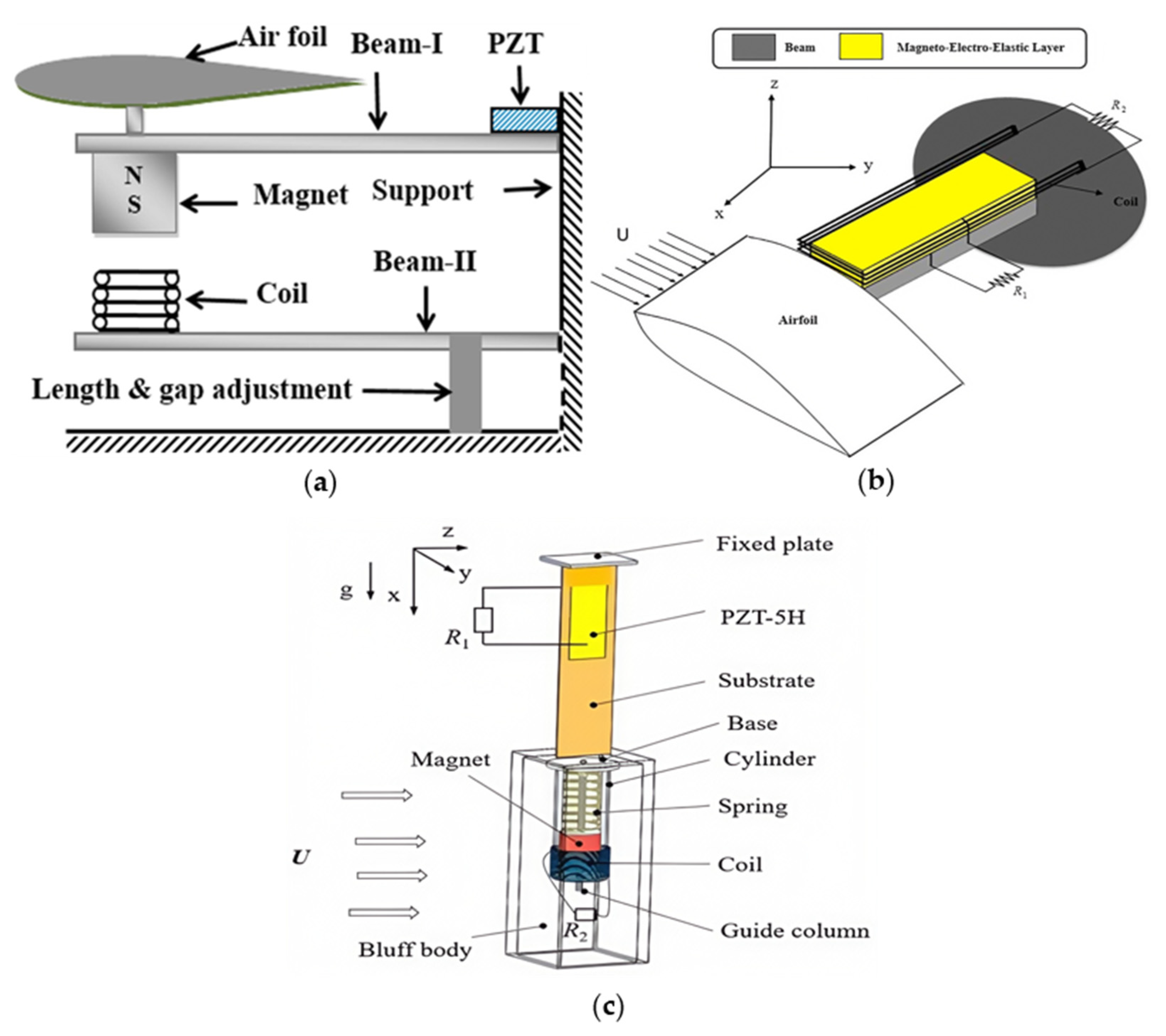
2.3. Based on Flutter

Flutter is a self-excited FIV phenomenon triggered by the interaction between the fluid and the structure [52]. When wind flows over a structure, the airflow generates varying pressure distributions on the surface, resulting in aerodynamic forces. Flexible structures undergo bending or twisting deformation under the action of the aerodynamic forces. The deformations, in turn, alter the direction and magnitude of the aerodynamic forces, generating forces that are out of phase with the structural motion, known as lag forces. When the structure undergoes small-amplitude vibrations, the aerodynamic forces change in response to the structure’s motion. As the wind speed increases, the aerodynamic forces gradually couple with the structure’s natural frequency, leading to a resonance effect. When the vibration frequency approaches or matches the structure’s natural frequency, the structure continuously absorbs energy, causing the vibration amplitude to grow rapidly. At the cut-in wind speed, a positive feedback loop forms between the aerodynamic forces and the structural deformation. The aerodynamic forces drive the structure’s vibrations, and the vibrations, in turn, amplify the aerodynamic forces. This positive feedback causes the vibration amplitude to continuously increase, ultimately leading to structural instability or even failure.
The governing equations of electromagnetic flutter WEHs may be expressed as [42,53]
m T h ¨ + m f x α b α ¨ + c h h ˙ + k h h θ e I = L
m f x α b h ¨ + I α α ¨ + c α α ˙ + k α α = M
θ e h ˙ L c I ˙ R + R c I = 0
where h represents the vertical displacement, α is the rotational angle, m T is the equivalent mass of the device, m f denotes the mass of the airfoil, I α is the mass moment of inertia about the elastic axis, x α is the dimensionless distance between the center of mass and the elastic axis, b represents the semi-chord length, c h is the plunge damping coefficient, c α is the pitch damping coefficient, k h is the plunge stiffness, k α is the pitch stiffness, θ e is the electromagnetic coupling, L c is the coil inductance, R is the resistance of electrical load, R c is the coil’s internal resistance, and L and M are the aerodynamic lift and moment, respectively.
Through a quasi-steady approximation with a stall effect, the aerodynamic loads are given by [54]
L = ρ U 2 b s c l α α e f f c s α e f f 3
M = ρ U 2 b 2 s c m α α e f f c s α e f f 3
where ρ is the air density, s denotes the airfoil span, c l α is the aerodynamic lift coefficient, c m α is the aerodynamic moment coefficient, and c s is a nonlinear parameter associated with stall. The effective angle of attack is expressed as
α e f f = α + h ˙ U + 0.5 a b α ˙ U
where α denotes the position of the elastic axis relative to the mid-chord.
The electromagnetic flutter WEHs have made significant progress in recent years. Park et al. [55] proposed a T-shaped flutter-based electromagnetic energy harvester, which cleverly utilizes the large vortex structures generated by the T-shaped cantilever under wind loading. This induces rotational instability, and through the relative motion between magnets and coils, electric current is generated, enabling energy conversion. The key to this design lies in optimizing the flutter onset wind speed and load resistance. Through numerical fluid dynamics (CFD) simulations and experimental validation, the significant impact of flutter derivatives and aerodynamic damping effects on system performance was revealed, laying a theoretical foundation for subsequent research.
In terms of parameter optimization and performance enhancement, Dinh Quy et al. [56] and Chawdhury et al. [57] optimized the performance of flutter WEHs and T-shaped cantilever systems by adjusting parameters such as wind speed, magnet position and size, membrane tension, angle of attack, generator orientation, as well as cantilever length, thickness, and tip height. Experimental results show that reasonable adjustments of these parameters can significantly improve energy harvesting efficiency, enabling the harvester to perform well even under low-wind-speed conditions.
In addition, an electromagnetic flutter-based WEH was introduced by Liu et al. [58] aimed at harvesting energy from pitching oscillations of an airfoil structure. Through the application of an equivalent linearization approach, they identified operating regions characterized by single-stable and double-stable limit cycle oscillations (LCO), concluding that stable LCO regimes are more conducive to effective energy conversion.
Lu et al. [59] formulated an analytical model for a ribbon-type electromagnetic wind energy harvester driven by flutter dynamics. Their analysis elucidated key parameters that govern optimal performance at low wind speeds, thereby offering theoretical guidance for the design of ribbon-based structures. Vinayan et al. [60] implemented an electromagnetic ribbon harvester utilizing taffeta silk as the structural medium. Their experimental investigation examined the influence of magnet position, ribbon width, wind speed, and ribbon tension on the electrical output. Under conditions of 12 m/s wind speed and 1.224 N ribbon tension, and with four coils connected in parallel, the system achieved a peak output voltage of 21.00 V and a power output of 346.08 mW.
Based on Lu et al.’s model, Zakaria et al. [61] further investigated the flutter-based electromagnetic wind energy harvesting performance of ribbon structures, finding a positive correlation between wind speed, magnet size, and model length with voltage generation, thus contributing to a better understanding of windbelt performance and identifying opportunities to optimize windbelt design and placement.
The structures of the electromagnetic flutter WEHs mentioned above are shown in Figure 3.

2.4. Based on Wake Galloping

Wake galloping primarily occurs when one object is situated in the wake of another object. The upstream object generates a wake as it moves through the fluid, which affects the downstream object. The vortices and uneven flow in the wake exert unstable fluid forces on the downstream object. These forces cause the downstream object to vibrate, with the amplitude and frequency depending on the fluid velocity, the characteristics of the object, and their relative position [62]. The lift and drag forces exerted by the fluid on the downstream object vary with the distance between the objects. When the distance is appropriate, the influence of the wake can induce significant vibrations. The occurrence of wake galloping is closely related to the spacing between the objects and the flow velocity. If the distance between the objects is too large, the vibration may weaken, whereas a smaller distance may significantly enhance the vibrations.
According to the studies of Tokoro [63] (as cited in Jung [64], 2011), Jung [64], and others, wake galloping exhibits the following notable characteristics (see Figure 4 for a typical energy harvesting system based on this phenomenon). First, the occurrence of wake galloping is related to the Scruton number, which is defined as: S c = m ζ ρ D 2 , where m is the mass per unit length of the object, ζ is the damping ratio, ρ is the air density, and D is the diameter of the cylinder. This phenomenon exists over a wide range of wind speeds, but at high wind speeds, it may disappear due to changes in the Reynolds number. Secondly, the vibration amplitude of wake galloping is influenced by various factors, including the structural characteristics, flow conditions, and wind direction. Generally, as the wind speed increases, the vibration amplitude also increases. However, the maximum vibration amplitude typically does not exceed three times the cylinder diameter. This is because, as the relative wind angle of parallel cylinders increases, the stability of wake interference decreases. When the wind direction deviates more significantly from the optimal alignment, the wake becomes less stable, reducing the effectiveness of the wake-induced vibrations and limiting the amplitude. Finally, the spacing between cylinders is a key parameter influencing the characteristics of wake galloping. In the range of 2D to 6D spacing, the wake galloping phenomenon is particularly pronounced. At a spacing of approximately 3D, vibrations can increase dramatically. However, at a spacing of around 5D, the vibration amplitude tends to increase gradually. This behavior is due to the way the wake interacts with the downstream object. At smaller spacings (e.g., 3D), the wake-induced forces are more concentrated, leading to larger oscillations. As the spacing increases to around 5D, the interaction between the wakes becomes less intense, resulting in a more gradual increase in vibration amplitude.
The study on wake galloping WEHs mainly focused on the wake systems of two tandem cylinders with different diameters. It has been found that the critical spacing that divides the two states (i.e., the attached-type and synchronized shedding-type flow structures) is determined by the length of the vortex formation behind the upstream cylinder. This critical spacing allows the flow structure to transition from a “heavy attachment” type to a “synchronized shedding” type. Based on the spacing ratio L/d, the flow interactions between two cylinders are classified into three states. The first state is the expansion state. For small spacing ratios (L/d = 1 to 1.2–1.8), the cylinders are placed relatively close together. In this state, the free shear layer separated from the upstream cylinder directly crosses over the downstream cylinder without reattaching to its surface, resulting in the formation of a Kármán vortex street behind the cylinders. The second state is the reattachment state. For moderate spacing ratios (L/d = 1.2–1.8 to 3.4–3.8), the shear layer separated from the upstream cylinder reattaches to the downstream cylinder, rolls up to form vortices, and alternately sheds from both sides of the downstream cylinder. The third state is the synchronized shedding state. When L/d > 3.8, vortex streets are formed not only between the two cylinders but also behind the cylinders. In this state, both cylinders shed vortices in a synchronized manner, leading to a more complex wake structure [65,66,67].
The flow around two tandem square cylinders has also been investigated. Zhou et al. [68] studied the flow characteristics of the wake behind two tandem square cylinders with spacing ratios L/d = 1.0~5.0 and Reynolds numbers Re = 2.8 × 10³~2.8 × 10⁴. Based on the variation in the Strouhal number (St) with L/d and the behavior of the separation shear layer, they categorized the flow states into four types: expansion state, reattachment state, transition state, and another transition state. They found that the wake behavior behind square cylinders differs significantly from that behind circular cylinders. In the wake of circular cylinders, two distinct bistable states exist, while in the wake of square cylinders, only one bistable state and one stable reattachment state are observed. Additionally, the separation angle and vortex formation length in the wake of square cylinders show a stronger dependence on the Reynolds number compared to circular cylinders, with a more pronounced dependency.
A pioneering contribution in this domain was made by Jung et al. [69], who demonstrated the feasibility of utilizing the wake galloping mechanism for enhanced electromagnetic energy conversion. Wind tunnel experiments revealed that their system achieved average power outputs ranging from 50 to 370 mW under wind speeds of 2.5–4.5 m/s. This performance underscores the potential of wake galloping harvesters to deliver substantial energy output even within relatively low-wind-speed regimes, marking a significant departure from conventional fixed-direction flow-induced vibration systems.
Building on the concept of exploiting wake dynamics, Sarviha et al. [70] investigated a novel harvesting configuration designed to operate under low-frequency vortex shedding conditions. Their approach introduced wall-induced constraints that actively modulate the vortex street behind a bluff body. In this system, a flexible diaphragm transmits wake-induced oscillations to an internal magnet, which in turn induces voltage in surrounding coils. The electromagnetic conversion is further enhanced by additional permanent magnets embedded along the flow path. The bluff body, modeled as a square cylinder, was found to generate alternating vortex structures that efficiently excite the diaphragm. Experimental comparisons confirmed that tandem bluff body arrangements outperform single-cylinder setups, and the influence of wall confinement was shown to depend strongly on bluff body geometry—demonstrating the effectiveness of geometric and boundary condition control in optimizing wake energy harvesting.
Further refinement of this diaphragm-based system was pursued by Sarviha et al. [71], who analyzed the effects of electrical load resistance, magnet size, and bluff body positioning on energy conversion efficiency. Through experimentation involving a pair of fixed circular cylinders, the study offered the first empirical validation of energy harvesting directly from wake-induced oscillations using diaphragm-coupled structures. The findings highlight the viability and scalability of such systems, especially under configurations where flow-induced pressure fluctuations can be efficiently transferred to the energy transducer via compliant interfaces.
Expanding the scope of wake-induced mechanisms, Liu et al. [72] proposed a rotational energy harvesting architecture driven by wake-induced angular galloping. The design integrates a torsional spring with a dual-magnet electromagnetic converter, enabling the downstream bluff body to undergo rotational oscillations about a fixed axis, while the upstream body remains stationary to maintain consistent wake excitation. A magnet affixed to the rotating body interacts with two stationary magnets to form a magnetic spring that facilitates self-restoring torque. Energy conversion is achieved through iron-core coils located across a narrow air gap, enabling efficient flux variation. At a wind speed of 10 m/s, the system achieved a peak average power output of 9.3 mW, validating the potential of rotational galloping harvesters for efficient energy extraction in wake-rich flow environments.
Collectively, these contributions illustrate the growing maturity of electromagnetic harvesters based on wake-induced oscillations. By leveraging complex interactions between bluff body geometries, wake patterns, structural compliance, and electromagnetic coupling, these systems present promising pathways for low- to moderate-speed wind energy harvesting with improved directionality, power density, and flow adaptability.
The electromagnetic wake galloping WEHs mentioned above are shown in Figure 5.
The fluid dynamic phenomena involved in wake galloping are typically more complex and exhibit highly nonlinear characteristics. The formation and evolution of the wake are influenced by multiple factors, including flow velocity, object shape, and angle, among others. It is more challenging to make the wake galloping WEHs maintain high electrical outputs in a wide wind speed range than the galloping or flutter WEHs.

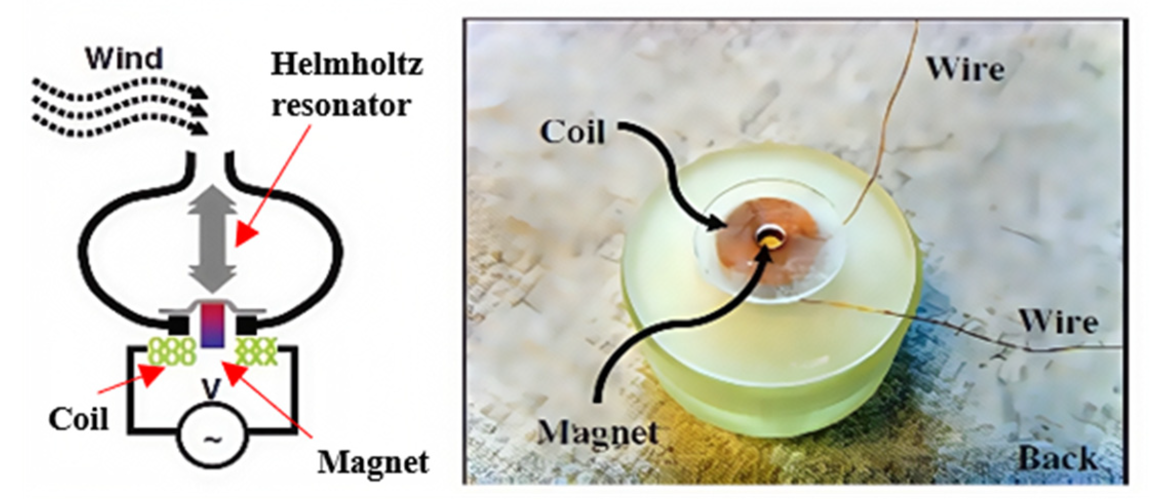
2.5. Based on Helmholtz Resonator

The Helmholtz resonator consists of a large-volume cavity and a narrow opening, with compression and expansion caused by airflow generating vibrations at specific frequencies. The resonant frequency can be adjusted by modifying the cavity volume, opening area, and air properties, making it sensitive to low-frequency airflow variations. Electromagnetic WEHs based on the Helmholtz resonator combine self-excited vibrations and resonance effects from FIVs. This allows them to generate stable mechanical vibrations using the kinetic energy of airflow, even under varying wind speeds, which are then converted into electrical energy. When the resonant frequency of the cavity is close to the natural frequency of the harvester, the harvester amplifies the vibration amplitude, enabling effective accumulation and conversion of mechanical energy. The vibration of the harvester structure causes relative motion between the magnets and coils, inducing a current in the coils.
Kim et al. [73] designed an electromagnetic WEH based on the Helmholtz resonator, as shown in Figure 6. The elastic structure consisting of a diaphragm and magnet is integrated into the Helmholtz resonator as the bottom wall of the chamber. When the natural frequency of the elastic structure is close to the resonant frequency of the Helmholtz resonator, the electrical output of metal coils fixed on the bottom housing of the chamber can be maximized. Experimental results show that the Helmholtz resonator-based energy harvester generates a peak-to-peak output voltage of 4 mV at an input pressure of 0.2 kPa, with a frequency of 1.4 kHz, corresponding to a wind speed of 5 m/s.
The electromagnetic WEHs based on the Helmholtz resonator face challenges due to complex multi-physics coupling, limited acoustic-induced motion, and strict geometric constraints for resonance tuning. Their performance is further hindered by unsteady wind conditions, structural integration difficulties, and limited experimental validation, which collectively restrict their practical deployment in applications. In contrast, the piezoelectric WEHs based on the Helmholtz resonator can achieve energy conversion without requiring large displacements. They offer a more compact structure, faster response, and flexible frequency tuning, making them better suited for low-frequency, small-amplitude excitations and more adaptable to practical engineering constraints. Therefore, there are more reports on piezoelectric WEHs based on the Helmholtz resonator [74,75].

2.6. Comparisons Among Electromagnetic WEHs Based on Different FIV Phenomena

The output performances of the aforementioned electromagnetic WEHs based on VIV, galloping, flutter, and wake galloping are listed in Table 1.
Abdelkefi [42] reviewed the progress of piezoelectric and electromagnetic WEHs based on VIV, galloping, flutter, and wake galloping. All the WEHs based on FIVs can produce high electrical outputs only when the wind speed is in a specified range. The VIV WEH works well when the wind speed is in the synchronization region and is considered inefficient when the wind speed varies in a wide range. The galloping and flutter WEHs produce electrical outputs when the wind speed is higher than the cut-in speed and work well in a much wider wind speed range than the VIV WEHs. In addition, VIV WEHs have lower output power than the galloping and flutter WEHs. These conclusions are also applicable to electromagnetic WEHs.

3. Performance Enhancement Methods

3.1. Output Power Enhancement

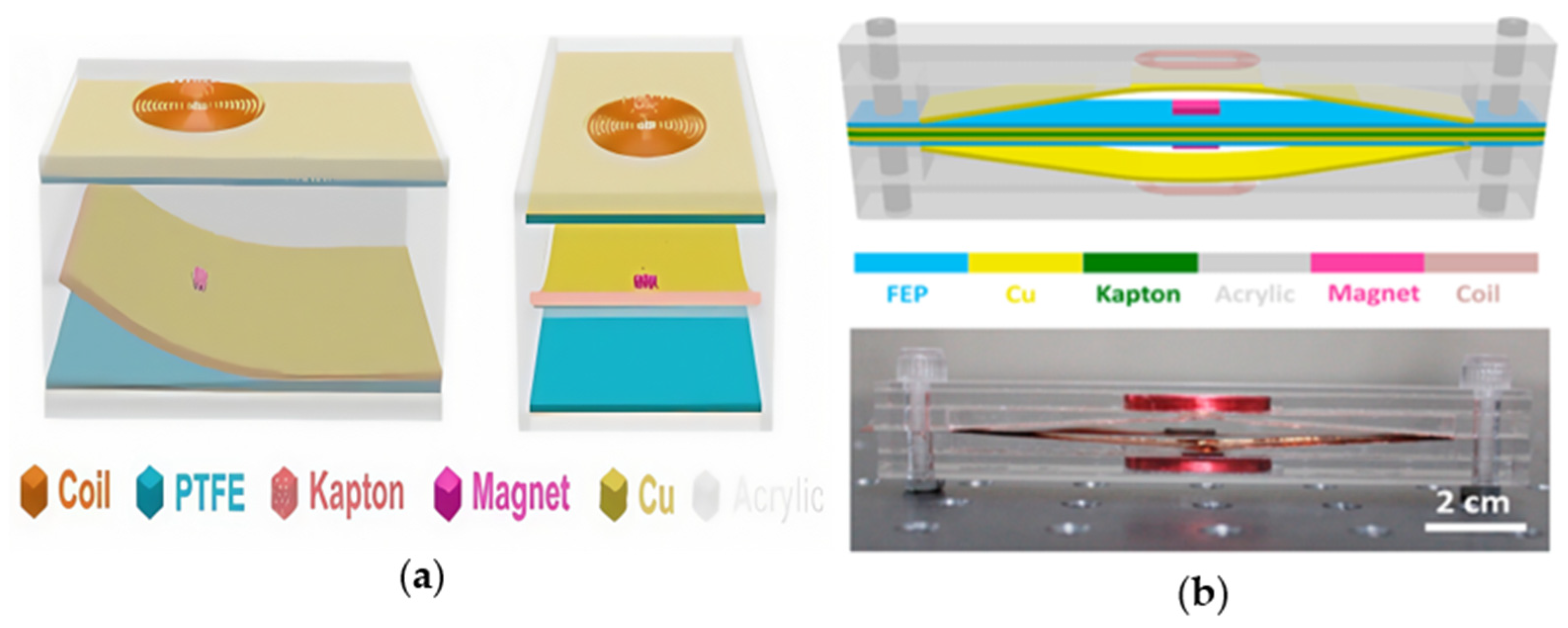
3.1.1. Hybrid Electromechanical Conversion

Improving the output power of energy harvesters can power more types of wireless sensor nodes, which is one of the research focuses for expanding the application scenarios. The hybrid energy harvesters simultaneously utilize multiple electromechanical conversion mechanisms to convert the structural vibration energy into electrical energy, thereby increasing the output power and extending operational bandwidth under FIV conditions.
The integration of piezoelectric and electromagnetic conversion mechanisms has been extensively investigated in hybrid energy harvester designs. Iqbal et al. [76] designed a novel multi-modal hybrid vibration and wind energy harvester that combines piezoelectric and electromagnetic conversions. Under specific wind speeds and load impedances, the electromagnetic transducer (ET) and piezoelectric transducer (PT) generated significant voltages, showcasing the potential of hybrid systems in wind energy harvesting.
Javed et al. [77] explored a VIV-based WEH incorporating both piezoelectric and electromagnetic mechanisms. They derived a nonlinear reduced-order model and compared the performance of the hybrid configuration with pure piezoelectric and electromagnetic counterparts. It was found that the external load resistance and the position of the magnet have a significant impact on the response, while the magnet mass had a relatively small effect. By optimizing the properties of the piezoelectric layer and the selection of external load resistance, the hybrid harvester demonstrated high efficiency within a specific wind speed range, capable of powering multiple electronic devices.
Li et al. [78] constructed an electromechanical coupling framework to examine the performance of a hybrid VIV WEH. They compared the output power of the hybrid VIV WEH and classical piezoelectric VIV WEH with the variation in wind speed. The results revealed that the power response curve of hybrid VIV WEH exhibits two peaks. The operational wind speed range of the power curve above 0.1 mW of the hybrid VIV WEH is 2.25 times that of the traditional piezoelectric VIV WEH.
In flutter-based configurations, Abdehvband et al. [79] examined a continuous model comprising a rigid airfoil coupled to an elastic beam with both piezoelectric and electromagnetic transducers. Their findings indicated that maximum power generation occurs at the flutter velocity threshold, with the electromagnetic transducer outperforming the piezoelectric unit by approximately 13.7% in peak power output. This result emphasizes the advantage of combining distinct transduction mechanisms to exploit flutter-induced vibrations effectively.
Additionally, Li et al. [80] integrated an electromagnetic transducer within the blunt body of a piezoelectric–electromagnetic hybrid flutter harvester. Vibration at the cantilever tip induces relative motion between embedded magnets and coils, enabling energy conversion. Experimental data demonstrated that at a wind speed of 9 m/s, the hybrid system’s power output exceeded that of a conventional piezoelectric harvester by 121%, highlighting the substantial performance gain achievable through integrated hybrid designs.
These studies highlight that hybridization not only boosts energy output but also improves adaptability to wind fluctuations. This is primarily attributed to the complementary nature of the two mechanisms: the piezoelectric component is effective under mechanical strain, while the electromagnetic unit leverages relative motion for efficient induction. These synergistic effects make hybrid WEHs promising candidates for stable and scalable energy harvesting in real-world variable wind conditions.
The piezoelectric–electromagnetic hybrid WEHs mentioned above are shown in Figure 7.
To overcome the limitations of low output power from triboelectric nanogenerators (TENGs) and high excitation wind speeds required for electromagnetic generators (EMGs), researchers have begun exploring hybrid energy harvesting systems that combine TENGs with EMGs. This combination not only maintains good energy collection efficiency across a wide range of wind speeds but also allows for the design of more compact and portable harvesters, which is especially important for portable devices.
Theoretical analyses by Zhang et al. [81] and Zi et al. [82] confirmed a symmetrical relationship between TENGs and EMGs, showing that TENG output scales linearly with frequency at low excitation, while EMG output scales quadratically—thereby establishing the rationale for hybridization. Zhang et al. [81] conducted a detailed comparison of the theoretical models of TENGs and EMGs, revealing the symmetrical relationship between the two. Subsequently, Zi et al. [82] found that under low-frequency motion, the output performance of TENGs is roughly proportional to the frequency, while the output of EMGs is proportional to the square of the frequency. This further confirms the advantage of TENGs at low frequencies and the potential of EMGs at high frequencies.
The EMG-TENG hybrid nanogenerator is categorized into vibration-based EMG-TENG and rotation-based EMG-TENG [83]. The vibration-based mechanical structure is a simple, efficient, and widely adaptable EMG-TENG manufacturing method that works through basic contact or sliding. In contrast to the more complex rotating EMG-TENGs that require rotating parts, bearings, gears, and other mechanical components, the vibration-based system can maintain a high energy collection efficiency under variable wind speeds and directions by utilizing vibration signals at different frequencies and nonlinear designs.
Among hybrid architectures, vibration-based TENG–EMG systems are particularly favored for their structural simplicity, adaptability to varying wind conditions, and suitability for miniaturization. Unlike rotation-based systems requiring complex mechanical components (e.g., gears, bearings), vibration-based designs enable efficient energy conversion using contact or sliding interfaces and nonlinear resonant responses. For example, Wang et al. [84,85] demonstrated a vibration-driven hybrid nanogenerator in which airflow-induced oscillations of a Kapton film simultaneously excited both EMG and TENG modes. The energy harvested was sufficient to power multiple temperature sensors, and subsequent improvements in structural fixation and power management circuits significantly enhanced charging rates and output stability.
In terms of flutter-based energy harvesting, Kim et al. [86] investigated a hybrid generator based on flutter, with the triboelectric component utilizing a contact-separation mode. The negative material was fluorinated ethylene propylene (FEP), and the positive material was aluminum. The electromagnetic component consisted of a horizontally wound coil and a neodymium magnet at the top. The device was enclosed in a small wind tunnel structure, and when wind acted on the system, both TENG and EMG collected energy simultaneously. The TENG generated a maximum voltage of 100 V and a current of 2 μA, while the EMG produced a voltage of 200 mV and a current of 200 mA. This design is suitable for powering low-power electronic devices and charging commercial capacitors.
The electromagnetic–triboelectric hybrid WEHs mentioned above are shown in Figure 8. The output performance of the various hybrid electromagnetic–triboelectric WEHs mentioned above is listed in Table 2.
PT-ET and TENG-EMG hybrid systems exhibit complementary advantages under different wind conditions and application scenarios. The PT-ET system features a relatively mature structure, typically integrating piezoelectric layers onto elastic beams or bluff bodies with embedded electromagnetic modules, resulting in a compact configuration that facilitates simulation and parameter optimization. It is particularly suitable for applications involving structural health monitoring or stable environments with resonant excitation. Multiple studies (e.g., Javed et al. [77], Li et al. [78,80]) have demonstrated that PT-ET systems achieve high energy conversion efficiency at moderate wind speeds. By optimizing piezoelectric materials and load matching, dual-peak power output can be realized, significantly broadening the operational wind speed range—for instance, Li et al. reported that the effective output range of the hybrid VIV device was 2.25 times wider than that of traditional piezoelectric harvesters. However, EM–PE systems are sensitive to resonance frequency tuning and load impedance matching, and the brittleness of materials such as PZT limits their applicability in large-deformation scenarios.
In contrast, TENG-EMG systems are structurally more complex, incorporating flexible membranes, triboelectric materials, electrodes, and coils, along with precisely designed contact–separation or sliding mechanisms. These systems are sensitive to contact pressure and mechanical wear but offer excellent low-frequency performance and wide wind speed adaptability. Their ability to operate under non-resonant and turbulent wind conditions is particularly notable, as demonstrated in studies by Wang et al. [84,85] and Kim et al. [86], where TENGs provided high voltage while EMGs supplied high current in a complementary manner. Nevertheless, long-term durability remains a challenge due to friction-induced degradation, which affects output consistency and system reliability.
Regarding manufacturing cost, TENG-EMG systems utilize commercial piezoelectric ceramics and copper coils, which are relatively mature in terms of fabrication, yielding moderate costs. In comparison, TENG-EMG systems rely on low-cost polymers and metal electrodes, but require high-precision micro/nanopatterning techniques to form efficient contact interfaces, thereby limiting mass-production efficiency. Overall, TENG-EMG systems have greater industrial scalability, particularly when integrated into existing MEMS or modular packaging processes. Meanwhile, TENG-EMG systems are more suitable for low-power, wearable, or distributed applications. Future work should tailor the choice between PT-ET and TENG-EMG systems to specific use cases by balancing efficiency, structural complexity, and fabrication cost, while also exploring opportunities for integration and optimization.

3.1.2. Nonlinear Effects

The incorporation of nonlinear effects in the design of WEHs could effectively enhance the output performance. By introducing nonlinear mechanisms into FIV WEHs, it is possible to not only expand the operational range and reduce the cut-in wind speed, but also significantly enhance the electrical output. Li et al. [87] proposed a magnetic-coupled piezoelectric–electromagnetic hybrid galloping WEH, which enhances the output power through a bistable nonlinear magnetic coupling structure. They found that the higher the coupling degree between the two components, the stronger the nonlinear characteristics, and the better the output performance. Compared to the conventional piezoelectric galloping WEHs, the piezoelectric–electromagnetic hybrid galloping WEH achieved a 28% reduction in cut-in wind speed and a 136% increase in output power. Li et al. [88] developed a magnetic-coupled bi-stable piezoelectric–electromagnetic hybrid flutter WEH and established its mathematical model. Both the simulations and experiments demonstrate that the introduction of the magnetic-coupled bi-stability could reduce the cut-in speed and enhance the output voltage. At a wind speed of 18 m/s, the piezoelectric and electromagnetic transducers achieved peak output powers of 14.5 mW and 31.8 mW, respectively.

3.2. Operational Wind Speed Range Expansion

The FIV WEHs produce relatively high electrical outputs only when the wind speed is within a specific range. Therefore, in order to expand the application scenarios, it is necessary to broaden their operational wind speed range. Multi-stable states have been used to lower the cut-in speed of piezoelectric–electromagnetic hybrid WEHs [87,88]. The interaction between VIV and galloping has been utilized to expand the wind speed range of piezoelectric galloping WEHs to the lower cut-in speed [89,90,91], with concurrent VIV and flutter used to improve the performance of a piezoelectric WEH at low wind speeds [92], and concurrent galloping and flutter used to improve the performance of piezoelectric–triboelectric hybrid WEHs at low wind speeds [93]. Sun et al. [94] adopted a movable bluff body to expand the operational wind speed range of a piezoelectric galloping WEH. By elaborately designing the movement of the bluff body, the cut-in speed can be lowered, and the power in a high-speed regime can be enhanced. Yang et al. [95] developed a VIV-galloping interactive piezoelectric WEH that adopts a deformable Y-type bluff body to expand the operational wind speed range. Chen et al. [96] proposed a two-degree-of-freedom nonlinear piezoelectric galloping WEH with ultra-low cut-in wind speed utilizing the quasi-zero stiffness near the initial position caused by magnetic force. Liu et al. [97] utilized the nonlinear stiffness caused by magnetic force to expand the operational wind speed range of a piezoelectric WEH to higher speeds. It is expected that multi-stable states, concurrent multiple FIV phenomena, movable or deformable bluff body, and nonlinear stiffness can also be used to expand the operational wind speed range of electromagnetic WEHs.

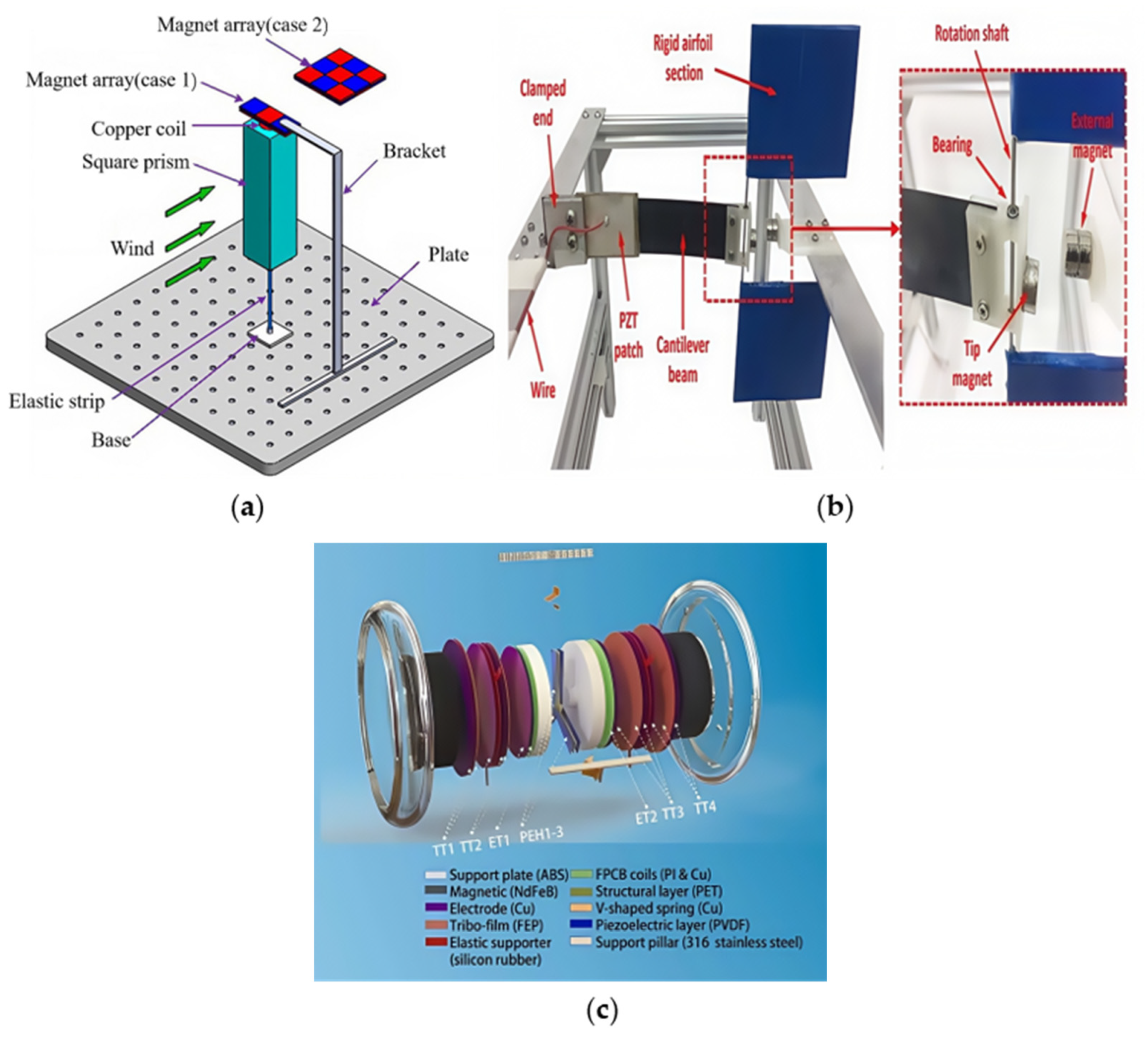
3.3. Operational Wind Direction Range Expansion

In practical WEH applications, temporal fluctuations in wind direction often compromise the performance of conventional FIV-based systems, which are typically optimized for a fixed or narrow directional range. Such directional constraints substantially reduce energy conversion efficiency when the incident wind deviates from the design orientation. As a result, enhancing directional adaptability has become a central objective in the ongoing development of WEH technologies.
One strategy to overcome this limitation involves the integration of structural configurations capable of maintaining performance across multiple wind directions. For instance, Zhang et al. [98] introduced a multi-directional electromagnetic galloping WEH that employs a 3 × 3 magnet array to amplify magnetic flux variation independently of wind orientation. This approach enables consistent energy harvesting under changing wind directions. Experimental evaluations at a wind speed of 2 m/s and a load resistance of 50 Ω demonstrated a peak power output of 0.124 mW, validating its applicability to low-speed, multi-directional environments.
To improve directional responsiveness, Li et al. [99] implemented a rotatable bluff body mechanism that allows passive alignment with the prevailing wind. This self-orienting feature ensures continuous vortex-induced vibrations, facilitating electricity generation through the relative motion of a permanent magnet and coil. Under a wind speed of 8 m/s, the system maintained a stable output of 0.673 mW, highlighting its suitability for dynamic wind conditions without the need for active orientation control.
Further advances have been achieved through the incorporation of multiple transduction mechanisms within a single configuration. Li et al. [100] presented an in-plane omni-directional hybrid energy harvester that combines electromagnetic, piezoelectric, and triboelectric modalities within a flutter-induced vibration framework. The use of a cylindrical bluff body with nearly isotropic stiffness in both pitching and plunging directions enables consistent mechanical response and efficient electromechanical conversion throughout a full 360° wind direction range. Experimental results indicated a maximum average power output of 6.84 mW at a wind speed of 20 m/s, with reliable operation maintained across a broad wind velocity range (3.6–20 m/s). These findings underscore the efficacy of hybrid, structurally adaptive designs in accommodating multi-directional and variable-speed wind scenarios.
The multi-directional electromagnetic WEHs mentioned above are shown in Figure 9. The output performance of the several multi-directional electromagnetic WEHs mentioned above is shown in Table 3. The study on multi-directional electromagnetic WEHs is still limited, and more research on the operational wind direction range expansion needs to be conducted in the future.

3.4. Durability Enhancement

The electromechanical conversion components of the majority of FIV WEHs are exposed to the external environment. For WEHs that are used to power the wireless sensor nodes deployed in outdoor environments, rainwater, dust, and corrosive substances will seriously affect their durability. In order to improve the survival ability in the wild, the durability of electromagnetic and piezoelectric WEHs was improved by deploying partly electromechanical conversion components in the blunt bodies [80,101,102,103,104], and the durability of piezoelectric and triboelectric WEHs was enhanced through superhydrophobic and self-cleaning coatings [105,106]. The study on electromagnetic WEHs with a protective external bluff body and self-cleaning, superhydrophobic coatings needs to be strengthened in the future.

4. Discussion

Among electromagnetic WEHs based on various FIV mechanisms, galloping WEHs are found to offer the most balanced performance, combining relatively high output power, broad operational wind speed range, and moderate structural complexity, making them particularly suitable for practical deployment. Electromagnetic flutter WEHs can also achieve high output power and broad operational wind speed range, but often require complex, multi-degree-of-freedom designs, which may hinder scalability. In contrast, electromagnetic VIV WEHs exhibit structural simplicity but are limited by the low output power and narrow operational wind speed range. Wake galloping and Helmholtz resonator-based mechanisms remain in early stages of development, with challenges such as unstable dynamic responses, narrow bandwidths, and integration difficulties yet to be resolved.
Despite the relatively low cut-in wind speeds (typically 1–4 m/s) reported for many electromagnetic wind energy harvesters, as shown in Table 1, the corresponding output power at such wind speed conditions is generally insufficient to drive wireless sensor nodes or other practical loads. In most cases, higher wind speeds (e.g., above 4 m/s) are required to generate usable power levels. This highlights a key limitation in real-world deployment, especially in urban or sheltered environments where average wind speeds may remain low for extended periods. Consequently, further research is needed to improve the power density of harvesters operating under low-wind-speed conditions, potentially through structural optimization, nonlinear coupling mechanisms, or magnetic circuit enhancement. Conversely, in extreme weather scenarios where wind speeds exceed 20 m/s, excessive vibration amplitudes may lead to mechanical fatigue or structural failure. To mitigate these risks, the implementation of mechanical stoppers or other components can be used to avoid excessive deformation. These measures contribute to extending operational lifespan and improving the overall robustness of the device under high-wind conditions.
Although significant progress has been made in optimizing the performance of electromagnetic WEHs, there remains a notable deficiency in standardized metrics for comprehensive cross-study comparison and evaluation. At present, no unified standard exists that simultaneously encompasses key parameters such as wind speed range, power output, and durability. Moreover, these performance indicators are often reported separately under varying experimental conditions, which hinders direct comparison and objective assessment of different designs. To advance the field toward development, there is an urgent need to establish comprehensive testing and evaluation frameworks that integrate environmental conditions, mechanical reliability, and normalized performance metrics. This review highlights this critical gap and advocates for future research efforts to focus on the formulation and adoption of unified standards to facilitate steady technological progress and broader implementation of electromagnetic WEHs.
Practical outdoor deployment presents significant environmental challenges, including exposure to rain, dust, humidity, and corrosive agents, all of which can adversely affect the performance and longevity of electromagnetic WEHs. Documented failure modes include magnet corrosion, coil insulation degradation, and obstruction or fatigue of mechanical components. However, no universally accepted standards currently exist for evaluating the environmental reliability of micro-scale WEHs. As such, assessing their long-term durability remains difficult. The operational lifespan of these systems largely depends on material selection, structural integrity, and the effectiveness of protective strategies. For instance, NdFeB magnets are prone to corrosion-induced demagnetization, though surface treatments like nickel or epoxy coatings can mitigate this risk. Similarly, coil insulation may degrade due to thermal and moisture cycling, and prolonged vibration can lead to mechanical fatigue. While various protective approaches have been proposed, long-term outdoor testing remains essential to validate the reliability and practical applicability of these devices under real-world conditions.
Another important consideration is the performance of WEHs under complex and unsteady natural wind environments. Unlike controlled laboratory conditions, outdoor wind is highly turbulent, with frequent fluctuations in speed and direction. These fluctuations can destabilize target vibration modes, detune resonance conditions, and activate unintended dynamic responses, ultimately reducing energy conversion efficiency. Systems optimized for steady-state lab conditions may underperform or fail altogether when deployed outdoors. Consequently, research on adaptability-enhancing strategies—such as using multi-stable mechanisms or directionally adaptive structures—must be supported by long-duration outdoor testing and robust structural engineering to ensure practical effectiveness.
In addition to structural and environmental concerns, electromagnetic WEHs must also address potential electromagnetic compatibility (EMC) issues. During operation, the relative motion between magnets and coils generates electromagnetic interference (EMI), which may adversely affect nearby sensitive electronics, including wireless communication modules (e.g., Bluetooth, Wi-Fi, ZigBee), microcontrollers, and magnetometers. Both radiated and conducted EMI can disrupt signal transmission and logic operations. Mitigation strategies include magnetic shielding with high-permeability materials, maintaining safe separation distances, incorporating LC filters and proper grounding, and utilizing conductive or metalized enclosures. Furthermore, alternating the operation timing of energy harvesting and wireless communication can minimize overlap and enhance overall system compatibility, which is critical for applications in low-power wireless sensor networks.
To further support uninterrupted operation in energy-constrained environments, the integration of electromagnetic WEHs with energy storage systems has emerged as a key area of research. Particularly in remote or off-grid scenarios—such as field monitoring, isolated communication outposts, or ecological observation platforms—this integration can enable autonomous, self-sustaining operation. As highlighted by Citroni et al. [107], coupling electromagnetic WEHs with miniature storage units like supercapacitors or lithium-ion batteries, alongside low-power management strategies, allows for stable power output and dynamic load matching. Harb [108] similarly emphasized the critical role of energy storage in maintaining system availability under fluctuating wind conditions. Coordinated design of harvesting and storage subsystems will be essential for scaling up the deployments of intelligent sensing nodes in harsh, variable environments.
Moreover, long-term field data are still scarce, particularly for durability-related evaluations. These factors should be considered when interpreting the conclusions drawn from the reviewed works.

5. Conclusions

Significant progress has been made in the development of electromagnetic WEHs. This review examined the working principles, structural features, and application scenarios of electromagnetic WEHs based on various FIV mechanisms, including VIV, galloping, flutter, wake galloping, and Helmholtz resonators. Current studies demonstrate that electromagnetic VIV WEHs can effectively reduce cut-in wind speed through the optimization of bluff body geometry and the natural frequency of the harvester, while electromagnetic galloping and flutter WEHs enable high power output over a broad wind speed range, making them particularly suitable for environments with fluctuating wind speed conditions.
Notable innovations in performance enhancement include the synergistic integration of multiple FIV modes (e.g., VIV–galloping hybrids), nonlinear stiffness and multi-stable structures, and the incorporation of sliding or pendulum-based coupling mechanisms. These approaches have significantly extended the operational bandwidth and improved energy conversion efficiency. Additionally, hybrid energy conversion strategies (e.g., electromagnetic–piezoelectric combinations), adaptive bluff bodies, and variable-stiffness composite beams have been explored to improve system adaptability under complex wind conditions.
Nevertheless, several critical research gaps remain. Electromagnetic WEHs based on Helmholtz resonators—which offer strong resonant amplification at low frequencies—are still underexplored, particularly in terms of cavity–structure coupling, electromagnetic transduction, and miniaturization strategies. Furthermore, most existing electromagnetic WEHs are uni-directional and lack responsiveness to variable wind directions, limiting their applicability in outdoor environments.
To address these limitations, future research should focus on (1) the development of omni-directional energy harvesting architectures based on structural symmetry or reconfigurable structures; (2) the use of advanced, fatigue-resistant, and corrosion-proof materials to enhance durability; and (3) the integration of miniaturized Helmholtz resonator designs with magnetic levitation mechanisms to improve low-wind-speed activation and long-term stability.
In summary, electromagnetic FIV-WEHs, owing to their high output power and excellent durability, are expected to be increasingly applied in fields such as wireless sensor networks in the future.

Author Contributions

Conceptualization, Y.Z. and S.L.; formal analysis, Y.Z., P.Z. and Y.Y.; Investigation, W.W., Y.Y. and C.L.; writing—original draft preparation, Y.Z., S.L. and X.H.; writing—review and editing, Y.Z. and X.H.; supervision, X.H.; funding acquisition, X.H. All authors have read and agreed to the published version of the manuscript.

Funding

This work is supported by the R&D project of State Grid Corporation of China (No. 5700-202458255A-1-1-ZN).

Institutional Review Board Statement

Not applicable.

Informed Consent Statement

Not applicable.

Data Availability Statement

Data are contained within the article.

Conflicts of Interest

Author Pengfei Zen, Chunlong Li were employed by the company State Grid Smart Grid Research Institute Co., Ltd. The remaining authors declare that the research was conducted in the absence of any commercial or financial relationships that could be construed as a potential conflict of interest.

Abbreviations

The following abbreviations are used in this manuscript:
FIVFlow-Induced Vibration
WEHsWind Energy Harvesters
FIVsFlow-Induced Vibrations
VIVVortex-Induced Vibration
CFDComputational Fluid Dynamics
LCOLimit Cycle Oscillations
ETElectromagnetic Transducer
PTPiezoelectric Transducer
TENGsTriboelectric Nanogenerators
EMGsElectromagnetic Generators
FEPFluorinated Ethylene Propylene
EMCElectromagnetic Compatibility
EMIElectromagnetic Interference

References

  1. Jia, R.; Zhang, H. Wireless sensor network (WSN) model targeting energy efficient wireless sensor networks node coverage. IEEE Access 2024, 12, 27596–27610. [Google Scholar] [CrossRef]
  2. Jamshed, M.A.; Ali, K.; Abbasi, Q.H.; Imran, M.A.; Ur-Rehman, M. Challenges, applications, and future of wireless sensors in Internet of Things: A review. IEEE Sens. J. 2022, 22, 5482–5494. [Google Scholar] [CrossRef]
  3. Chen, M.; Yu, Y.; Ouyang, D.; Weng, J.; Zhao, L.; Wang, J.; Chen, Y. Research progress of enhancing battery safety with phase change materials. Renew. Sustain. Energy Rev. 2024, 189, 113921. [Google Scholar] [CrossRef]
  4. Maka, A.O.; Alabid, J.M. Solar energy technology and its roles in sustainable development. Clean Energy 2022, 6, 476–483. [Google Scholar] [CrossRef]
  5. Opolot, M.; Zhao, C.; Liu, M.; Mancin, S.; Bruno, F.; Hooman, K. A review of high temperature (≥ 500 °C) latent heat thermal energy storage. Renew. Sustain. Energy Rev. 2022, 160, 112293. [Google Scholar] [CrossRef]
  6. Zhou, S.; Lallart, M.; Erturk, A. Multistable vibration energy harvesters: Principle, progress, and perspectives. J. Sound Vib. 2022, 528, 116886. [Google Scholar] [CrossRef]
  7. Roga, S.; Bardhan, S.; Kumar, Y.; Dubey, S.K. Recent technology and challenges of wind energy generation: A review. Sustain. Energy Technol. Assess. 2022, 52, 102239. [Google Scholar] [CrossRef]
  8. Shepherd, D.G. Historical Development of the Windmill; (No. NASA-CR-4337); NASA: Washington, DC, USA, 1990. [Google Scholar]
  9. Ackermann, T.; Söder, L. Wind energy technology and current status: A review. Renew. Sustain. Energy Rev. 2020, 4, 315–374. [Google Scholar] [CrossRef]
  10. Ackermann, T.; Söder, L. An overview of wind energy-status 2002. Renew. Sustain. Energy Rev. 2002, 6, 67–127. [Google Scholar] [CrossRef]
  11. Smil, V. World history and energy. Encycl. Energy 2004, 6, 549–561. [Google Scholar]
  12. Wang, H.; Xiong, B.; Zhang, Z.; Zhang, H.; Azam, A. Small wind turbines and their potential for internet of things applications. iScience 2023, 26, 107674. [Google Scholar] [CrossRef]
  13. Antonini, E.G.; Virgüez, E.; Ashfaq, S.; Duan, L.; Ruggles, T.H.; Caldeira, K. Identification of reliable locations for wind power generation through a global analysis of wind droughts. Commun. Earth Environ. 2024, 5, 103. [Google Scholar] [CrossRef]
  14. Zhang, L.B.; Abdelkefi, A.; Dai, H.L.; Naseer, R.; Wang, L. Design and experimental analysis of broadband energy harvesting from vortex-induced vibrations. J. Sound Vib. 2017, 408, 210–219. [Google Scholar] [CrossRef]
  15. Barrero-Gil, A.; Alonso, G.; Sanz-Andres, A. Energy harvesting from transverse galloping. J. Sound Vib. 2010, 329, 2873–2883. [Google Scholar] [CrossRef]
  16. Olivieri, S.; Boccalero, G.; Mazzino, A.; Boragno, C. Fluttering conditions of an energy harvester for autonomous powering. Renew. Energy 2017, 105, 530–538. [Google Scholar] [CrossRef]
  17. Alhadidi, A.H.; Daqaq, M.F. A broadband bi-stable flow energy harvester based on the wake-galloping phenomenon. Appl. Phys. Lett. 2016, 109, 033904. [Google Scholar] [CrossRef]
  18. Covaci, C.; Gontean, A. Piezoelectric energy harvesting solutions: A review. Sensors 2020, 20, 3512. [Google Scholar] [CrossRef] [PubMed]
  19. Zhu, D.; Beeby, S.P.; Tudor, M.J.; White, N.M.; Harris, N.R. Novel Miniature Airflow Energy Harvester for Wireless Sensing Applications in Buildings. IEEE Sens. J. 2013, 13, 691–700. [Google Scholar] [CrossRef]
  20. Fan, F.-R.; Tian, Z.-Q.; Lin Wang, Z. Flexible triboelectric generator. Nano Energy 2012, 1, 328–334. [Google Scholar] [CrossRef]
  21. Khaligh, A.; Onar, O.C. Energy Harvesting: Solar, Wind, and Ocean Energy Conversion Systems; CRC Press: Boca Raton, FL, USA, 2017. [Google Scholar]
  22. Priya, S.; Song, H.C.; Zhou, Y.; Varghese, R.; Chopra, A.; Kim, S.G.; Kanno, I.; Wu, L.; Ha, D.S.; Ryu, J.; et al. A review on piezoelectric energy harvesting: Materials, methods, and circuits. Energy Harvest. Syst. 2019, 4, 3–39. [Google Scholar] [CrossRef]
  23. Dong, X.; Liu, Z.; Yang, P.; Chen, X. Harvesting wind energy based on triboelectric nanogenerators. Nanoenergy Adv. 2022, 2, 245–268. [Google Scholar] [CrossRef]
  24. Yan, J.; Tang, Z.; Mei, N.; Zhang, D.; Zhong, Y.; Sheng, Y. Research progress on the application of triboelectric nanogenerators for wind energy collection. Micromachines 2023, 14, 1592. [Google Scholar] [CrossRef] [PubMed]
  25. Williamson, C.H.K.; Govardhan, R. A brief review of recent results in vortex-induced vibrations. J. Wind. Eng. Ind. Aerodyn. 2008, 96, 713–735. [Google Scholar] [CrossRef]
  26. Lupi, F.; Niemann, H.-J.; Höffer, R. Aerodynamic damping model in vortex-induced vibrations for wind engineering applications. J. Wind. Eng. Ind. Aerodyn. 2018, 174, 281–295. [Google Scholar] [CrossRef]
  27. Francis, S.; Swain, A. Modelling and harnessing energy from flow-induced vibration, particularly VIV and galloping: An explicit review. Ocean Eng. 2024, 312, 119290. [Google Scholar] [CrossRef]
  28. Fukushima, H.; Yagi, T.; Shimoda, T.; Noguchi, K. Wake-induced instabilities of parallel circular cylinders with tandem and staggered arrangements. J. Wind. Eng. Ind. Aerodyn. 2021, 215, 104697. [Google Scholar] [CrossRef]
  29. Chai, Y.; Gao, W.; Ankay, B.; Li, F.; Zhang, C. Aeroelastic analysis and flutter control of wings and panels: A review. Int. J. Mech. Syst. Dyn. 2021, 1, 5–34. [Google Scholar] [CrossRef]
  30. Xu, C.; Zhao, L. Internal resonance in galloping, VIV, and flutter for concurrent wind and base vibration energy harvesting. In Active and Passive Smart Structures and Integrated Systems XVI; SPIE: Bellingham, WA, USA, 2022; Volume 12043, pp. 227–237. [Google Scholar]
  31. Hasheminejad, S.M.; Masoumi, Y. Dual-functional synergetic energy harvesting and flow-induced vibration control of an electromagnetic-based square cylinder integrated with a flexible bimorph piezoelectric wake splitter plate. Renew. Energy 2023, 216, 119133. [Google Scholar] [CrossRef]
  32. Ma, X.; Zhou, S. A review of flow-induced vibration energy harvesters. Energy Convers. Manag. 2022, 254, 115223. [Google Scholar] [CrossRef]
  33. Feng, C.C. The Measurement of Vortex Induced Effects in Flow Past Stationary and Oscillating Circular and D-Section Cylinders. Ph.D. Dissertation, University of British Columbia, Vancouver, BC, Canada, 1968. [Google Scholar]
  34. Jeon, D.; Gharib, M. On circular cylinders undergoing two-degree-of-freedom forced motions. J. Fluids Struct. 2001, 15, 533–541. [Google Scholar] [CrossRef]
  35. Jauvtis, N.A.; Williamson, C.H.K. The effect of two degrees of freedom on vortex-induced vibration at low mass and damping. J. Fluid Mech. 2004, 509, 23–62. [Google Scholar] [CrossRef]
  36. Zhu, D.; Beeby, S.; Tudor, J.; White, N.; Harris, N. A novel miniature wind generator for wireless sensing applications. In Proceedings of the SENSORS, 2010 IEEE, Waikoloa, HI, USA, 1–4 November 2010; pp. 1415–1418. [Google Scholar]
  37. Wang, D.A.; Chiu, C.Y.; Pham, H.T. Electromagnetic energy harvesting from vibrations induced by Kármán vortex street. Mechatronics 2012, 22, 746–756. [Google Scholar] [CrossRef]
  38. Xu-Xu, J.; Barrero-Gil, A.; Velazquez, A. A theoretical study of the coupling between a vortex-induced vibration cylindrical resonator and an electromagnetic energy harvester. Smart Mater. Struct. 2015, 24, 115009. [Google Scholar] [CrossRef]
  39. Atrah, A.B.; Ab-Rahman, M.S.; Salleh, H.; Nuawi, M.Z.; Mohd Nor, M.J.; Jamaludin, N.B. Karman vortex creation using cylinder for flutter energy harvester device. Micromachines 2017, 8, 227. [Google Scholar] [CrossRef] [PubMed]
  40. Huang, X.; Zhong, T. Hydrokinetic energy harvesting from flow-induced vibration of a hollow cylinder attached with a bi-stable energy harvester. Energy Convers. Manag. 2023, 278, 116718. [Google Scholar] [CrossRef]
  41. Moradi Gharghani, F.; Bijarchi, M.A.; Mohammadi, O.; Shafii, M.B. An experimental investigation into a novel small-scale device for energy harvesting using vortex-induced vibration. Int. J. Low-Carbon Technol. 2021, 16, 317–325. [Google Scholar] [CrossRef]
  42. Abdelkefi, A. Aeroelastic energy harvesting: A review. Int. J. Eng. Sci. 2016, 100, 112–135. [Google Scholar] [CrossRef]
  43. Dai, H.L.; Yang, Y.W.; Abdelkefi, A.; Wang, L. Nonlinear analysis and characteristics of inductive galloping energy harvesters. Commun. Nonlinear Sci. Numer. Simul. 2018, 59, 580–591. [Google Scholar] [CrossRef]
  44. Zhang, L.B.; Dai, H.L.; Abdelkefi, A.; Lin, S.X.; Wang, L. Theoretical modeling, wind tunnel measurements, and realistic environment testing of galloping-based electromagnetic energy harvesters. Appl. Energy 2019, 254, 113737. [Google Scholar] [CrossRef]
  45. Xing, J.; Rezaei, M.; Dai, H.; Liao, W.-H. Investigating the effect of surface protrusions on galloping energy harvesting. Appl. Phys. Lett. 2023, 122, 153902. [Google Scholar] [CrossRef]
  46. Kim, H.; Kim, S.; Xue, K.; Seok, J. Modeling and performance analysis of electromagnetic energy harvester based on torsional galloping phenomenon. Mech. Syst. Signal Process. 2023, 195, 110287. [Google Scholar] [CrossRef]
  47. Le, H.D.; Kwon, S.-D. An electromagnetic galloping energy harvester with double magnet design. Appl. Phys. Lett. 2019, 115, 133901. [Google Scholar] [CrossRef]
  48. Le, H.D.; Kwon, S.D. Design and experiments of a galloping-based wind energy harvester using quadruple halbach arrays. Energies 2021, 14, 6094. [Google Scholar] [CrossRef]
  49. Su, B.; Wang, Y.; Li, J.; Guo, T.; Cheng, G.; Sun, W. A novel elastic strip suspension-based bi-directional electromagnetic wind energy harvester designed specifically for wind energy factories. Mech. Syst. Signal Process. 2024, 208, 111059. [Google Scholar] [CrossRef]
  50. Xiong, L.; Gao, S.; Jin, L.; Guo, S.; Sun, Y.; Liu, F. The Design and Experiment of a Spring-Coupling Electromagnetic Galloping Energy Harvester. Micromachines 2023, 14, 968. [Google Scholar] [CrossRef]
  51. Xiong, L.; Gao, S.; Jin, L.; Sun, Y.; Du, X.; Liu, F. Study on the Influence of Coil Arrangement on the Output Characteristics of Electromagnetic Galloping Energy Harvester. Micromachines 2023, 14, 2158. [Google Scholar] [CrossRef]
  52. Theodorsen, T. General Theory of Aerodynamic Instability and the Mechanism of Flutter (No. NACA-TR-496). 1979. Available online: https://ntrs.nasa.gov/citations/19800006788 (accessed on 3 June 2025).
  53. Li, Z.; Zhou, S.; Yang, Z. Recent progress on flutter-based wind energy harvesting. Int. J. Mech. Syst. Dyn. 2022, 2, 82–98. [Google Scholar] [CrossRef]
  54. Abdelkefi, A.; Nayfeh, A.H.; Hajj, M.R. Modeling and analysis of piezoaeroelastic energy harvesters. Nonlinear Dyn. 2012, 67, 925–939. [Google Scholar] [CrossRef]
  55. Park, J.; Morgenthal, G.; Kim, K.; Kwon, S.-D.; Law, K.H. Power evaluation of flutter-based electromagnetic energy harvesters using computational fluid dynamics simulations. J. Intell. Mater. Syst. Struct. 2004, 25, 1800–1812. [Google Scholar] [CrossRef]
  56. Dinh Quy, V.; Van Sy, N.; Tan Hung, D.; Quoc Huy, V. Wind tunnel and initial field tests of a micro generator powered by fluid-induced flutter. Energy Sustain. Dev. 2016, 33, 75–83. [Google Scholar] [CrossRef]
  57. Chawdhury, S.; Morgenthal, G. Numerical simulations of aeroelastic instabilities to optimize the performance of flutter-based electromagnetic energy harvesters. J. Intell. Mater. Syst. Struct. 2018, 29, 479–495. [Google Scholar] [CrossRef]
  58. Liu, S.; Li, P.; Yang, Y. On the design of an electromagnetic aeroelastic energy harvester from nonlinear flutter. Meccanica 2018, 53, 2807–2831. [Google Scholar] [CrossRef]
  59. Lu, Z.; Wen, Q.; He, X.; Wen, Z. A flutter-based electromagnetic wind energy harvester: Theory and experiments. Appl. Sci. 2019, 9, 4823. [Google Scholar] [CrossRef]
  60. Vinayan, V.A.; Yap, T.C.; Go, Y.I. Design of Aeroelastic Wind Belt for Low-Energy Wind Harvesting. IOP Conf. Ser. Earth Environ. Sci. 2019, 268, 012069. [Google Scholar] [CrossRef]
  61. Zakaria, N.M.; Zulkifli, M.S.; Mukhtar, A. The Potential of Flutter-Based Windbelt for Energy Generation in Low-Wind-Speed Regions: A Case Study in Malaysia. J. Adv. Res. Fluid Mech. Therm. Sci. 2023, 107, 125–141. [Google Scholar] [CrossRef]
  62. Kumar, S.K.; Bose, C.; Ali, S.F.; Sarkar, S.; Gupta, S. Investigations on a vortex induced vibration based energy harvester. Appl. Phys. Lett. 2017, 111, 243903. [Google Scholar] [CrossRef]
  63. Tokoro, S.; Komatsu, H.; Nakasu, M.; Mizuguchi, K.; Kasuga, A. A study on wake-galloping for stay cables of extradosed bridges employing full aeroelastic cable model. In Proceedings of the Wind Engineering into The 21st Century, Copenhagen, Denmark, 21–24 June 1999; pp. 1055–1062. [Google Scholar]
  64. Jung, H.-J.; Lee, S.-W.; Jang, D.-D. Feasibility Study on a New Energy Harvesting Electromagnetic Device Using Aerodynamic Instability. IEEE Trans. Magn. 2009, 45, 4376–4379. [Google Scholar] [CrossRef]
  65. Sumner, D. Two circular cylinders in cross-flow: A review. J. Fluids Struct. 2010, 26, 849–899. [Google Scholar] [CrossRef]
  66. Zhou, Y.; Mahbub Alam, M. Wake of two interacting circular cylinders: A review. Int. J. Heat Fluid Flow 2016, 62, 510–537. [Google Scholar] [CrossRef]
  67. Wang, L.; Alam, M.M.; Zhou, Y. Two tandem cylinders of different diameters in cross-flow: Effect of an upstream cylinder on wake dynamics. J. Fluid Mech. 2018, 836, 5–42. [Google Scholar] [CrossRef]
  68. Zhou, Y.; Hao, J.; Alam, M.M. Wake of two tandem square cylinders. J. Fluid Mech. 2024, 983, A3. [Google Scholar] [CrossRef]
  69. Jung, H.-J.; Lee, S.-W. The experimental validation of a new energy harvesting system based on the wake galloping phenomenon. Smart Mater. Struct. 2011, 20, 055022. [Google Scholar] [CrossRef]
  70. Sarviha, A.; Barati, E.; Zarkak, M.R. Electromagnetic energy harvesting via flow-induced vibration of flexible diaphragm in the presence of square cylinders at varied incidence angles: An experimental investigation. Mech. Syst. Signal Process. 2023, 202, 110696. [Google Scholar] [CrossRef]
  71. Sarviha, A.; Barati, E.; Zarkak, M.R.; Derakhshandeh, J.F.; Alam, M.M. Experimental investigations on the wake-induced vibration of an electromagnetic energy-harvesting system. Int. J. Energy Res. 2024, 2024, 7072340. [Google Scholar] [CrossRef]
  72. Liu, Y.; Liu, J.; Xue, K.; Seok, J. Development of a novel wake-induced rotational galloping wind energy harvester and the identification of its working mechanism. Mech. Syst. Signal Process. 2025, 224, 112019. [Google Scholar] [CrossRef]
  73. Kim, S.-H.; Ji, C.-H.; Galle, P.; Herrault, F.; Wu, X.; Lee, J.-H.; Choi, C.-A.; Allen, M.G. An electromagnetic energy scavenger from direct airflow. J. Micromechanics Microengineering 2009, 19, 094010. [Google Scholar] [CrossRef]
  74. Du, Z.G.; He, X.F. Micro piezoelectric wind energy harvester with a resonant cavity. Chin. J. Sensors Actuators 2012, 25, 748–750. [Google Scholar]
  75. Li, X.; Li, Z.; Liu, Q.; Shan, X. Study on the critical wind speed of a resonant cavity piezoelectric energy harvester driven by driving wind pressure. Micromachines 2019, 10, 842. [Google Scholar] [CrossRef]
  76. Iqbal, M.; Khan, F.U. Hybrid vibration and wind energy harvesting using combined piezoelectric and electromagnetic conversion for bridge health monitoring applications. Energy Convers. Manag. 2018, 172, 611–618. [Google Scholar] [CrossRef]
  77. Javed, U.; Abdelkefi, A. Characteristics and comparative analysis of piezoelectric-electromagnetic energy harvesters from vortex-induced oscillations. Nonlinear Dyn. 2019, 95, 3309–3333. [Google Scholar] [CrossRef]
  78. Li, X.; Li, Z.; Liu, B.; Zhang, J.; Zhu, W. Numerical research on a vortex shedding induced piezoelectric-electromagnetic energy harvester. J. Intell. Mater. Syst. Struct. 2022, 33, 105–120. [Google Scholar] [CrossRef]
  79. Abdehvand, M.Z.; Seyed Roknizadeh, S.A.; Mohammad-Sedighi, H. Modeling and analysis of novel coupled magneto-electro-aeroelastic continuous system for flutter-based energy harvesting system. Energy 2021, 230, 120742. [Google Scholar] [CrossRef]
  80. Li, X.; Bi, C.; Li, Z.; Liu, B.; Wang, T.; Zhang, S. A piezoelectric and electromagnetic hybrid galloping energy harvester with the magnet embedded in the bluff body. Micromachines 2021, 12, 626. [Google Scholar] [CrossRef] [PubMed]
  81. Zhang, C.; Tang, W.; Han, C.; Fan, F.; Wang, Z.L. Theoretical Comparison, Equivalent Transformation, and Conjunction Operations of Electromagnetic Induction Generator and Triboelectric Nanogenerator for Harvesting Mechanical Energy. Adv. Mater. 2014, 26, 3580–3591. [Google Scholar] [CrossRef] [PubMed]
  82. Zi, Y.; Guo, H.; Wen, Z.; Yeh, M.H.; Hu, C.; Wang, Z.L. Harvesting low-frequency (<5 Hz) irregular mechanical energy: A possible killer application of triboelectric nanogenerator. ACS Nano 2016, 10, 4797–4805. [Google Scholar] [CrossRef] [PubMed]
  83. Xu, L.; Hasan, M.A.M.; Wu, H.; Yang, Y. Electromagnetic–triboelectric hybridized nanogenerators. Energies 2021, 14, 6219. [Google Scholar] [CrossRef]
  84. Wang, X.; Wang, S.; Yang, Y.; Wang, Z.L. Hybridized Electromagnetic–Triboelectric Nanogenerator for Scavenging Air-Flow Energy to Sustainably Power Temperature Sensors. ACS Nano 2015, 9, 4553–4562. [Google Scholar] [CrossRef] [PubMed]
  85. Wang, X.; Yang, Y. Effective energy storage from a hybridized electromagnetic-triboelectric nanogenerator. Nano Energy 2017, 32, 36–41. [Google Scholar] [CrossRef]
  86. Kim, W.J. Development of Hybrid Generator Using Triboelectric-Electromagnetic Components for Scavenging Wind and Water Wave Energy. Ph.D. Dissertation, Jeju National University Graduate School, Jeju City, Republic of Korea, 2022. [Google Scholar]
  87. Li, X.; Ma, T.; Liu, B.; Wang, C.; Su, Y. Experimental Study on Magnetic Coupling Piezoelectric–Electromagnetic Composite Galloping Energy Harvester. Sensors 2022, 22, 8241. [Google Scholar] [CrossRef]
  88. Li, K.; Yang, Z.; Zhou, S. Performance enhancement for a magnetic-coupled bi-stable flutter-based energy harvester. Smart Mater. Struct. 2020, 29, 085045. [Google Scholar] [CrossRef]
  89. He, X.; Yang, X.; Jiang, S. Enhancement of wind energy harvesting by interaction between vortex-induced vibration and galloping. Appl. Phys. Lett. 2018, 112, 33901. [Google Scholar] [CrossRef]
  90. Wang, J.; Gu, S.; Zhang, C.; Hu, G.; Chen, G.; Yang, K.; Li, H.; Lai, Y.; Litak, G.; Yurchenko, D. Hybrid wind energy scavenging by coupling vortex-induced vibrations and galloping. Energy Convers. Manag. 2020, 213, 112835. [Google Scholar] [CrossRef]
  91. Del Priore, E.; Romano, G.P.; Lampani, L. Coupled electro-aeroelastic energy harvester model based on piezoelectric transducers, VIV-galloping interaction and nonlinear switching circuits. Smart Mater. Struct. 2023, 32, 075012. [Google Scholar] [CrossRef]
  92. Shan, X.; Tian, H.; Cao, H.; Xie, T. Enhancing performance of a piezoelectric energy harvester system for concurrent flutter and vortex-induced vibration. Energies 2020, 13, 3101. [Google Scholar] [CrossRef]
  93. Dong, L.; Hu, G.; Tang, Q.; Zhao, C.; Yang, F.; Yang, Y. Advanced Aerodynamics-Driven Energy Harvesting Leveraging Galloping-Flutter Synergy. Adv. Funct. Mater. 2025, 35, 2414324. [Google Scholar] [CrossRef]
  94. Sun, W.; Seok, J. Novel galloping-based piezoelectric energy harvester adaptable to external wind velocity. Mech. Syst. Signal Process. 2021, 152, 107477. [Google Scholar] [CrossRef]
  95. Yang, Z.; Zhang, Y.; Li, Z.; Lin, S.; Zhang, Z.; Kan, J. Design and characteristic analysis of a performance-enhanced piezoelectric wind energy harvester with a transformable Y-type bluff body. IEEE Sens. J. 2024, 24, 25360–25368. [Google Scholar] [CrossRef]
  96. Chen, S.; Zhao, L. A quasi-zero stiffness two degree-of-freedom nonlinear galloping oscillator for ultra-low wind speed aeroelastic energy harvesting. Appl. Energy 2023, 331, 120423. [Google Scholar] [CrossRef]
  97. Liu, F.R.; Zhao, L.C.; Yan, G.; Zhang, W.M.; Wu, Z.Y.; Zhang, X.L. Performing Magnetic Boundary Modulation to Broaden the Operational Wind Speed Range of a Piezoelectric Cantilever-Type Wind Energy Harvester. Micromachines 2024, 15, 1286. [Google Scholar] [CrossRef]
  98. Zhang, H.; Sui, W.; Yang, C.; Zhang, L.; Song, R.; Yang, X. Scavenging wind induced vibration by an electromagnet energy harvester from single to multiple wind directions. Ferroelectrics 2021, 577, 170–180. [Google Scholar] [CrossRef]
  99. Li, J.; Wang, G.; Yang, P.; Wen, Y.; Zhang, L.; Song, R.; Hou, C. An orientation-adaptive electromagnetic energy harvester scavenging for wind-induced vibration. Energy 2024, 286, 129578. [Google Scholar] [CrossRef]
  100. Li, S.; Chen, Z.; He, X.; Ye, Y.; Wan, S.; Dong, L. High performance hybrid omnidirectional wind energy harvester based on flutter for wireless sensing and hydrogen production applications. Nano Energy 2024, 132, 110403. [Google Scholar] [CrossRef]
  101. Zhang, M.; Hu, G.; Wang, J. Bluff body with built-in piezoelectric cantilever for flow-induced energy harvesting. Int. J. Energy Res. 2020, 44, 3762–3777. [Google Scholar] [CrossRef]
  102. Wang, S.; Liao, W.; Zhang, Z.; Liao, Y.; Yan, M.; Kan, J. Development of a novel non-contact piezoelectric wind energy harvester excited by vortex-induced vibration. Energy Convers. Manag. 2021, 235, 113980. [Google Scholar] [CrossRef]
  103. Li, S.; He, X.; Li, J.; Feng, Z.; Yang, X.; Li, J. An in-plane omnidirectional piezoelectric wind energy harvester based on vortex-induced vibration. Appl. Phys. Lett. 2022, 120, 43901. [Google Scholar] [CrossRef]
  104. Li, S.; Feng, Z.; He, X.; Ye, Y.; Li, J. An in-plane omnidirectional flutter piezoelectric wind energy harvester. Mech. Syst. Signal Process. 2023, 200, 110637. [Google Scholar] [CrossRef]
  105. Li, X.; He, X. Preparation of Superhydrophobic Coating with Silica Powder on Flexible Substrates. Nanosci. Nanotechnol. Lett. 2018, 10, 554–558. [Google Scholar] [CrossRef]
  106. Wu, Z.; Huang, J.; Zhao, Y.; Ding, X.; Chen, J.; Liu, Z.; Liu, Z.; Zhu, Y. Lotus leaf-inspired superhydrophobic piezoelectric nanofiber films for moisture-proof pressure sensing and energy harvesting. Chem. Eng. J. 2025, 504, 158874. [Google Scholar] [CrossRef]
  107. Citroni, R.; Mangini, F.; Frezza, F. Efficient integration of ultra-low power techniques and energy harvesting in self-sufficient devices: A comprehensive overview of current progress and future directions. Sensors 2024, 24, 4471. [Google Scholar] [CrossRef]
  108. Harb, A. Energy harvesting: State-of-the-art. Renew. Energy 2011, 36, 2641–2654. [Google Scholar] [CrossRef]
Figure 1. Electromagnetic VIV WEHs: (a) Electromagnetic WEH based on VIV [36]; (b) Electromagnetic WEH with the vibration induced by Kármán vortex streets [37]; (c) Piezoelectric-electromagnetic hybrid WEH with the vibration induced by vortex shedding [38]; (d) Physical model of a cylinder generating Kármán vortices [39]; (e) Schematic of a two-degree-of-freedom VIV WEH [40]; (f) VIV WEH consisting of a lightweight galvanized plate fixed with a hinge on one side and a spring on the other [41].
Energies 18 03835 g001
Figure 2. Electromagnetic galloping WEHs: (a) Schematic of electromagnetic WEH based on prism galloping [43]; (b) Electromagnetic galloping WEH [44]; (c) Electromagnetic WEH based on torsional galloping [46]; (d) Electromagnetic galloping WEH with dual magnet design [47]; (e) Electromagnetic WEH with four linear Halbach arrays [48]; (f) Parallel elastic strip suspended electromagnetic WEH [49]; (g) Schematic of a spring-coupling electromagnetic WEH [50].
Energies 18 03835 g002aEnergies 18 03835 g002b
Figure 3. Electromagnetic flutter WEHs: (a) T-shaped electromagnetic flutter WEH [55]; (b) Miniature electromagnetic WEH [56]; (c) Schematic of electromagnetic WEH [58]; (d) Ribbon-type electromagnetic flutter energy harvester [59]; (e) Ribbon-type electromagnetic energy harvester with four coils in parallel [60].
Energies 18 03835 g003aEnergies 18 03835 g003b
Figure 4. Energy harvesting system based on the wake galloping phenomenon of structures under wind load [64].
Energies 18 03835 g004
Figure 5. Electromagnetic wake galloping WEHs: (a) Wake-based electromagnetic WEH [69]; (b) Assembled diaphragm electromagnetic WEH [70]; (c) Diagram of diaphragm under loads [71]; (d) 3D schematic of wake-induced rotational galloping WEH [72].
Energies 18 03835 g005
Figure 6. Schematic and photograph of the electromagnetic WEH based on the Helmholtz resonator [73].
Energies 18 03835 g006
Figure 7. Piezoelectric–electromagnetic hybrid structures: (a) Multimodal hybrid WEH [76]; (b) Magnetoelectric aeroelastic energy harvester model [79]; (c) Piezoelectric–electromagnetic hybrid flutter WEH with embedded magnet in blunt body [80].
Energies 18 03835 g007
Figure 8. Electromagnetic–triboelectric hybrid WEHs: (a) One-end fixed hybrid electromagnetic–triboelectric WEH [84]; (b) Two-end fixed hybrid electromagnetic–triboelectric WEH [85].
Energies 18 03835 g008
Figure 9. Multi-directional electromagnetic WEHs: (a) Electromagnetic WEH with a 3 × 3 magnet array [98]; (b) Directional adaptive electromagnetic WEH [99]; (c) Omni-directional electromagnetic–piezoelectric–triboelectric hybrid flutter WEH [100].
Energies 18 03835 g009
Table 1. Output performance of electromagnetic WEHs based on different FIV phenomena.
Ref.FIV TypeCut-In Speed (m/s)Wind Speed (m/s)Output
Voltage (V)
Output Power (mW)
[36]VIV2.55 1.6
[37]VIV0.00177
[44]galloping1.542.5
[46]galloping2.75100.1180.31
[47]galloping1.541.41
[48]galloping128
[49]galloping243.207.8
[50]galloping7.5140.10320.79
[56]flutter383100
[57]flutter485.3
[59]flutter3100.705
[60]flutter21221.00346.08
[69]wake-galloping14.5370
[71]wake-galloping0.080.00202
[72]wake-galloping2.95100.29.3
Table 2. Output performance of electromagnetic–triboelectric hybrid WEHs.
Ref.FIV TypeElectromechanical TransductionWind Speed (m/s)Output
Voltage (V)
Output Power (mW)
[76]gallopingPT-ET6 V PT = 0.114 , V ET = 0.025 P PT = 0.1557 , P ET = 2.214
[78]VIVPT-ET5.46 V PT = 11.53 , V ET = 0.445 P PT = 1.9 , P ET = 2.2
[80]gallopingPT-ET9 V PT = 39.80 , V ET = 0.378 P PT = 1.68 , P ET = 3.57
[84]VIVTENG-EMG18 V TENG = 102.47 , V EMG = 1.897 P TENG = 3.5 , P EMG = 1.8
[85]VIVTENG-EMG18 V TENG = 130.38 , V EMG = 1 . 581 P TENG = 1.7 , P EMG = 2.5
[86]flutterTENG-EMG V TENG = 150 , V EMG = 0.283 P TENG = 0.225 , P EMG = 0.8
Table 3. Output performance of multi-directional electromagnetic WEHs.
Ref.FIV TypeWind Speed (m/s) Output
Voltage (V)
Output Power (mW)Resistance (Ω)
[98]galloping20.0790.12450
[99]VIV80.5500.673450
[100]flutter206.84
Disclaimer/Publisher’s Note: The statements, opinions and data contained in all publications are solely those of the individual author(s) and contributor(s) and not of MDPI and/or the editor(s). MDPI and/or the editor(s) disclaim responsibility for any injury to people or property resulting from any ideas, methods, instructions or products referred to in the content.

