Article

An Adaptive Control Strategy for a Virtual Synchronous Generator Based on Exponential Inertia and Nonlinear Damping

1
School of Energy and Power Engineering, Inner Mongolia University of Technology, Hohhot 010051, China
2
Inner Mongolia Power (Group) Co., Ltd., Hohhot 010020, China
3
Huaneng Wulatezhongqi New Energy Power Generation Co., Ltd., Bayannur 015200, China
*
Author to whom correspondence should be addressed.
Energies 2025, 18(14), 3822; https://doi.org/10.3390/en18143822
Submission received: 23 May 2025 / Revised: 10 July 2025 / Accepted: 16 July 2025 / Published: 18 July 2025
(This article belongs to the Section F3: Power Electronics)

Abstract

The increasing incorporation of renewable energy into power grids has significantly reduced system inertia and damping, posing challenges to frequency stability and power quality. To address this issue, an adaptive virtual synchronous generator (VSG) control strategy is proposed, which dynamically adjusts virtual inertia and damping in response to real-time frequency variations. Virtual inertia is modulated by an exponential function according to the frequency variation rate, while damping is regulated via a hyperbolic tangent function, enabling minor support during small disturbances and robust compensation during severe events. Control parameters are optimized using an enhanced particle swarm optimization (PSO) algorithm based on a composite performance index that accounts for frequency deviation, overshoot, settling time, and power tracking error. Simulation results in MATLAB/Simulink under step changes, load fluctuations, and single-phase faults demonstrate that the proposed method reduces the frequency deviation by over 26.15% compared to fixed-parameter and threshold-based adaptive VSG methods, effectively suppresses power overshoot, and eliminates secondary oscillations. The proposed approach significantly enhances grid transient stability and demonstrates strong potential for application in power systems with high levels of renewable energy integration.

1. Introduction

In recent years, driven by escalating energy crises and environmental pollution, renewable energy generation—particularly wind and photovoltaic power—has been widely promoted and rapidly developed worldwide. However, the large-scale integration of renewable energy into power systems has introduced the so-called ‘double-high’ characteristic: high renewable penetration and a high proportion of inverter-based resources. This trend has weakened the system’s inherent inertia and damping, thereby impairing its ability to resist disturbances and fluctuations [1]. To address these challenges, researchers worldwide have proposed Virtual Synchronous Generator (VSG) technology, inspired by the dynamic behavior of synchronous generators [2,3,4]. By emulating the stator voltage and rotor dynamics of synchronous generators, VSG allows grid-connected inverters in renewable energy systems to exhibit virtual inertia and damping, thereby enhancing their disturbance rejection capability and improving overall power system stability [5].
However, conventional VSG control strategies typically adopt fixed virtual inertia and damping coefficients. These static parameters fail to satisfy the diverse optimization requirements under varying operating conditions [6]. Under small disturbances, excessive inertia and damping may cause sluggish system response, while under large disturbances, insufficient inertia can result in rapid frequency decline [7]. Therefore, adaptively tuning inertia and damping parameters according to system conditions has emerged as a critical research focus.
In recent years, many researchers have proposed improved adaptive control strategies. One class of methods focuses on the adaptive regulation of virtual inertia. For example, Reference [8] proposed a bang-bang control strategy that adjusts the moment of inertia based on system acceleration and deceleration phases. When a rapid frequency drop is detected, the inertia is temporarily increased to support the system frequency and reduced during the recovery phase. Although this approach mitigates frequency fluctuations to some extent, abrupt parameter switching can lead to discontinuous control and induce additional disturbances. To overcome this issue, Reference [9] introduced a segmented exponential function to enable the smooth adjustment of virtual inertia. However, this method requires repeated tuning of key parameters in practical applications, thereby increasing design complexity and implementation cost.
Another class of methods focuses on enhancing the virtual damping mechanism. For instance, Reference [10] introduced additional damping through state feedback to improve the system’s damping ratio. Reference [11] further incorporated instantaneous damping compensation and angular frequency feedforward into the conventional VSG damping loop to enhance active power response. These enhancements have proven effective in increasing damping and mitigating active power oscillations.
Several studies have also investigated coordinated adaptive control of both virtual inertia and damping. For instance, Reference [12] proposed a co-adaptive VSG control strategy that dynamically tunes virtual inertia and damping based on system transients, significantly improving the frequency response in islanded microgrids. Although this approach simultaneously addresses inertia support and damping enhancement, it requires the meticulous tuning of multiple parameters to prevent adverse interactions. Reference [13] further employed a real-time analysis of load power and frequency deviations to adaptively adjust VSG parameters.
To enhance the intelligence of VSG control, advanced control and optimization algorithms have been introduced. For instance, Reference [14] employed model predictive control and multi-objective optimization for VSG parameter tuning to simultaneously satisfy dynamic and steady-state performance requirements. Other researchers have explored intelligent optimization techniques, including reinforcement learning, particle swarm optimization, and genetic algorithms, to achieve adaptive control of inertia and damping parameters [15,16,17,18]. Alongside the steady advancement of time-domain VSG control strategies, nonlinear frequency-domain dynamics are increasingly recognized as a valuable complement. For example, Reference [19] explored the oscillatory behavior and stability boundaries of inerter-based mechanical systems by integrating harmonic balance analysis with bifurcation theory. They proposed a frequency-dependent equivalent impedance model that offers theoretical guidance for the tuning of damping and inertance. Although originally developed for vehicular suspension systems, the analytical techniques employed are generalizable and can be extended to grid-forming inverter research. This cross-disciplinary approach enriches the dynamic performance evaluation of VSG systems and provides valuable insights for the development of more robust and adaptive control strategies.
In summary, existing enhanced methods still face several challenges, including parameter discontinuity, implementation complexity, and strong dependence on accurate system models. To address these issues, this paper proposes an adaptive VSG control strategy that integrates exponential inertia tuning with tanh-based nonlinear damping regulation. An objective function is formulated based on frequency deviation and active power output, and key control parameters are optimized using an improved particle swarm optimization (PSO) algorithm. Finally, a grid-connected inverter test system with VSG control is developed in MATLAB/Simulink, and simulation tests under various operating conditions are conducted to verify the feasibility of the proposed approach.

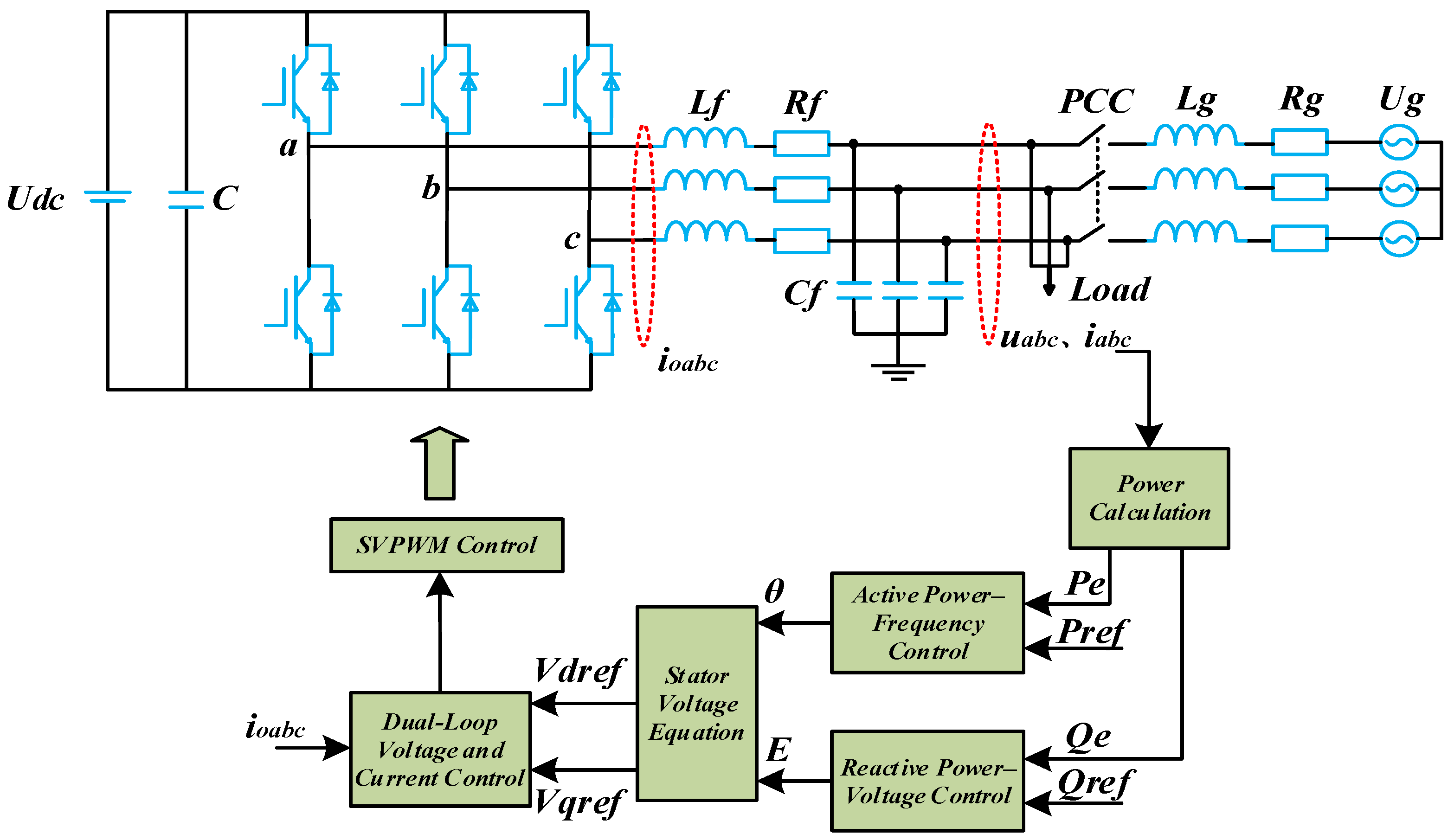
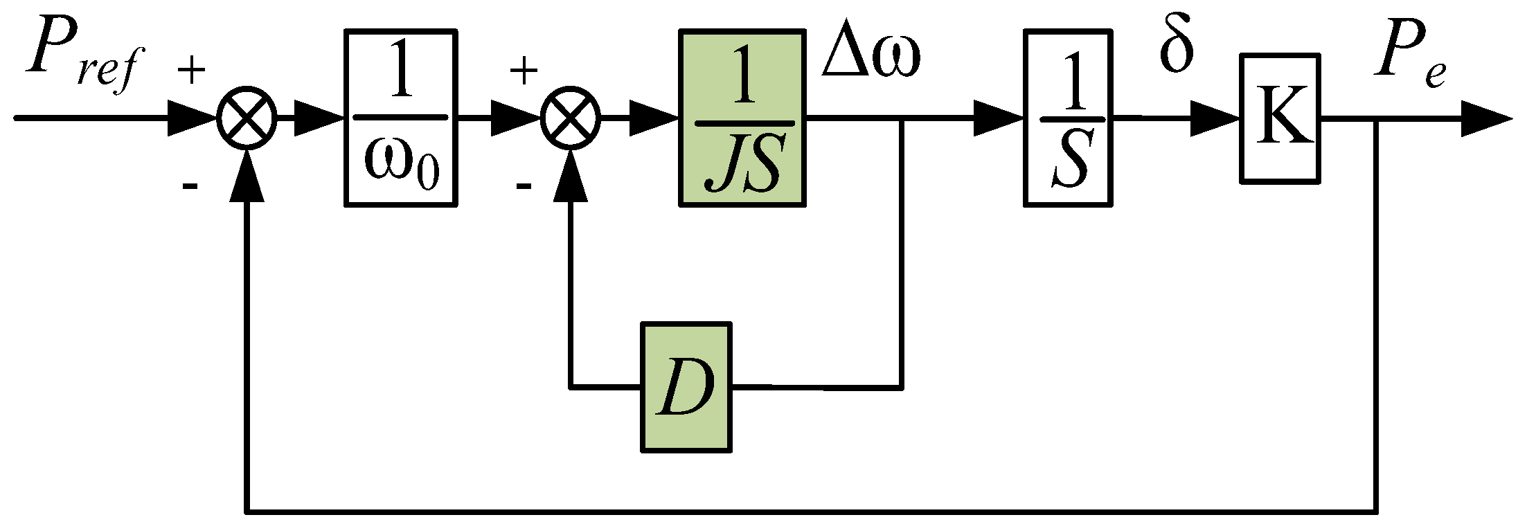
2. Fundamental Principles and Characteristic Analysis of VSG

As illustrated in Figure 1, Udc and Ug denote the DC bus voltage and grid-side voltages, respectively, while uabc and iabc represent the inverter’s three-phase output voltage and current. ioabc denotes the current through the filter inductors. Rf, Lf, and Cf correspond to the parasitic resistance of the inverter-side inductor, the filter inductance, and the filter capacitance, respectively. Rg and Lg represent the equivalent resistance and inductance on the grid side. Pref and Qref are the reference values for active and reactive power, respectively. “PCC” denotes the point of common coupling, while θ and E represent the output phase angle and voltage amplitude of the VSG.
The control strategy proposed in this study is primarily designed for PV–storage hybrid systems, in which photovoltaic units and energy storage devices are integrated into the grid through a shared DC bus via inverters. Considering the rapid response and millisecond-level frequency regulation capability of energy storage systems [20,21], this study focuses on optimizing the frequency control performance on the inverter side. Accordingly, the source-side dynamics are comparatively neglected, and the DC-link voltage Udc is assumed to be constant to simplify the modeling process and emphasize the inverter-side control dynamics.
In the control layer, the “Power Calculation” module measures the real-time output active and reactive power of the VSG. The “Reactive Power–Voltage Control” module determines the voltage amplitude E to regulate terminal voltage and reactive power. Signal E consists of three components: (1) a reference term simulating the internal electromotive force of a conventional synchronous generator, (2) an increment based on reactive power deviation, and (3) a correction term related to voltage deviation. The “Stator Voltage Equation” module uses E and θ to generate three-phase symmetrical sinusoidal voltage commands. These voltages are transformed into the rotating reference frame via an abc-dq transformation, yielding reference voltage vector components Vdref and Vqref. Meanwhile, the measured current ioabc undergoes the same transformation and, along with the voltage reference, enters the “Dual-Loop Voltage and Current Control” module. This module applies PI regulation via an outer voltage loop and an inner current loop to produce the voltage reference vector for modulation. The resulting voltage vector is then sent to the SVPWM (Space Vector Pulse Width Modulation) module, which calculates the switching duty cycles to drive the inverter, thereby achieving the VSG control objectives.
The “Active Power–Frequency Control” module of the VSG includes the rotor motion equation based on the second-order model of a synchronous generator, and a primary frequency control component that mimics the generator’s governor mechanism. The corresponding mathematical models are presented in Equations (1) and (2).
J d ω d t = P m ω 0 P e ω 0 D ( ω ω 0 ) ,
P m = P ref k ω ( ω ω 0 ) ,
Substituting Equation (2) into Equation (1) gives
J d ω d t = P r e f ω 0 P e ω 0 D e q ( ω ω 0 ) D e q = D + k w ω 0 ,
where J is the virtual moment of inertia (unit: kg·m2); ω and ω0 represent the angular velocity of the VSG and the nominal angular velocity, respectively (unit: rad/s); and Pm and Pe denote the mechanical and electromagnetic power, respectively. D is the damping coefficient (unit: N·m·s/rad). Since both the damping coefficient D and the frequency regulation coefficient kω contribute to power regulation via the frequency deviation term (ωω0), and the value of kω is relatively small, its dynamic effect is incorporated into D in this work to simplify the control structure.
In addition, based on the VSG circuit topology and the apparent power calculation principle, it is reasonable to assume that the equivalent impedance between the grid voltage and the inverter output voltage is predominantly inductive under practical conditions. Therefore, the output power of the VSG during grid-connected operation can be approximately expressed as
P e = 3 U g E 2 X sin δ 3 U g E 2 X δ = K δ ,
where δ is the power angle of the VSG; Ug and X represent the grid voltage amplitude and the equivalent line reactance, respectively; and K = 1.5 UgE/X denotes the synchronous voltage coefficient. As illustrated in Figure 2, the equivalent closed-loop control block diagram for the grid-connected active power of the VSG can be derived from the above analysis [22].
Based on the small-signal model, the transfer function between active power and frequency is derived as a typical second-order system, as shown in Equation (5).
G P ( s ) = Δ P e Δ P r e f = K J ω 0 s 2 + D ω 0 s + K G H z ( s ) = Δ ω Δ P ref = s J ω 0 s 2 + D ω 0 s + K ,
From the above equation, the natural angular frequency and damping ratio of the corresponding second-order VSG model can be derived as follows:
ω n = K J ω 0 ξ = D ω 0 2 1 K J ω 0 ,

3. Adaptive Control Strategy for VSG Parameters

3.1. Adaptive Inertia and Damping Control Algorithm

In modern power grids with increasing renewable energy integration, grid-connected VSGs must ensure robust dynamic and steady-state performance in both active power output and frequency [23]. Accordingly, this paper proposes an adaptive inertia–damping control strategy based on frequency-disturbance perception, which flexibly reinforces inertia and damping regulation while maintaining overall system stability, thereby enhancing disturbance resilience. Specifically, the control scheme incorporates an exponential inertia adjustment algorithm and a tanh-based nonlinear damping regulation, as defined by Equations (7) and (8):
J = J 0 + K j ( 1 e α | ω · | ) K j = K j _ min + ( K j _ max K j _ min ) | ω · | max ( | ω · | ) ,
D = D 0 + K d tanh ( β Δ ω ) Δ ω > 0 D = D 0 Δ ω 0 ,
Here, Δω = ωref − ω denotes the angular frequency deviation. J0 is the system’s base virtual inertia, providing essential inertia support. The coefficient Kj represents the inertia enhancement factor, whose value is constrained within the range [Kj_min, Kj_max] and varies linearly with the normalized value of ω ˙ . This design enables a rapid increase in inertia under severe disturbances to suppress frequency drops, while retaining J0 under mild or steady-state conditions to avoid unnecessary dynamic energy losses caused by excessive inertia. The parameter α determines the sensitivity of the inertia adjustment to ω ˙ , where a larger α accelerates the adaptation of virtual inertia.
In the damping regulation part, Kd is the damping enhancement magnitude, and β is the sensitivity coefficient of the damping regulation. When Δω > 0, indicating that the system frequency is below the nominal value (typically due to a sudden load increase or insufficient active power), appropriately enhancing the damping helps to suppress frequency oscillations, improve dynamic stability, and prevent large frequency deviations or overshoot. The introduced tanh (·) function, as a smooth nonlinear saturation function, allows the damping coefficient to increase gradually with respect to the frequency deviation Δω, and saturates under large disturbances, thereby effectively avoiding abrupt adjustments that may compromise system stability. When Δω ≤ 0, indicating that the system frequency is equal to or above the nominal value (such as in the case of sudden load shedding or excess active power), maintaining the base damping level is more conducive to smooth operation during frequency recovery. Excessive damping in this case may result in slower dynamic response or reduced control flexibility. Therefore, the damping coefficient is maintained at its baseline value D0 to ensure system stability and convergence during the frequency restoration stage.

3.2. Parameter Tuning

To ensure both practical applicability and optimal dynamic performance, this section first defines the boundary ranges of key control parameters based on engineering principles and standard references. An enhanced PSO algorithm is then employed to determine the optimal parameter set within these ranges.

3.2.1. Parameter Range Selection for Key Control Variables

In the proposed adaptive control strategy, the parameters α, Kd, and β play a critical role in shaping the dynamic behavior of virtual inertia and nonlinear damping. To ensure both rapid dynamic response and system stability, the parameter α is confined to the range of 1 × 10⁻⁴ to 1 × 10⁻², striking a balance between inertia adaptation speed and numerical stability. The gain Kd is selected within the range of 0 to 5 to ensure sufficient damping enhancement while avoiding excessive power oscillations. Meanwhile, β is varied between 1 and 30, allowing the nonlinear damping term to respond more aggressively to large frequency deviations while maintaining stability under small disturbances. These parameter ranges are determined based on system dynamic characteristics and extensive simulation-based empirical studies.
In addition, to prevent inadequate inertia support during small frequency deviations—which may amplify frequency fluctuations—the lower bound Kj_min should not be set too low. Conversely, an excessively high Kj_max may result in the overcompensation of inertia adjustment, leading to frequency overshoot or system oscillations. Considering typical system frequency deviation ranges and the required sensitivity of inertia regulation, this study sets Kj_min = 0.2 and Kj_max = 1.0.
According to the EN 50549-1-2019 standard [24], a VSG must be capable of adjusting its output power within the range of 40% to 100% of its rated capacity when the grid frequency deviation reaches 1 Hz. Based on this standard, the damping coefficient D is designed as follows:
D = Δ P ω Δ ω max Δ P ω 0 Δ ω max ,
In this equation, Δ ω max = 2 π . The rated capacity of the inverter designed in this paper is 100 kVA, from which the feasible range of the damping coefficient D is determined as 20.27 ≤ D ≤ 50.69. By equivalently transforming Equation (6), we obtain
J = ω o X D 2 6 ξ 2 U g E ,
In the above equation, X denotes the equivalent line reactance. To ensure a fast, dynamic response and short settling time of the VSG control system, the damping ratio ξ is typically set within the range of 0.6 to 1.0. Considering the gain margin and phase margin requirements of a second-order system, a damping ratio of 0.65 is selected in this study. Based on Equations (9) and (10), the feasible range of virtual inertia J is derived as 0.13 ≤ J ≤ 0.80.

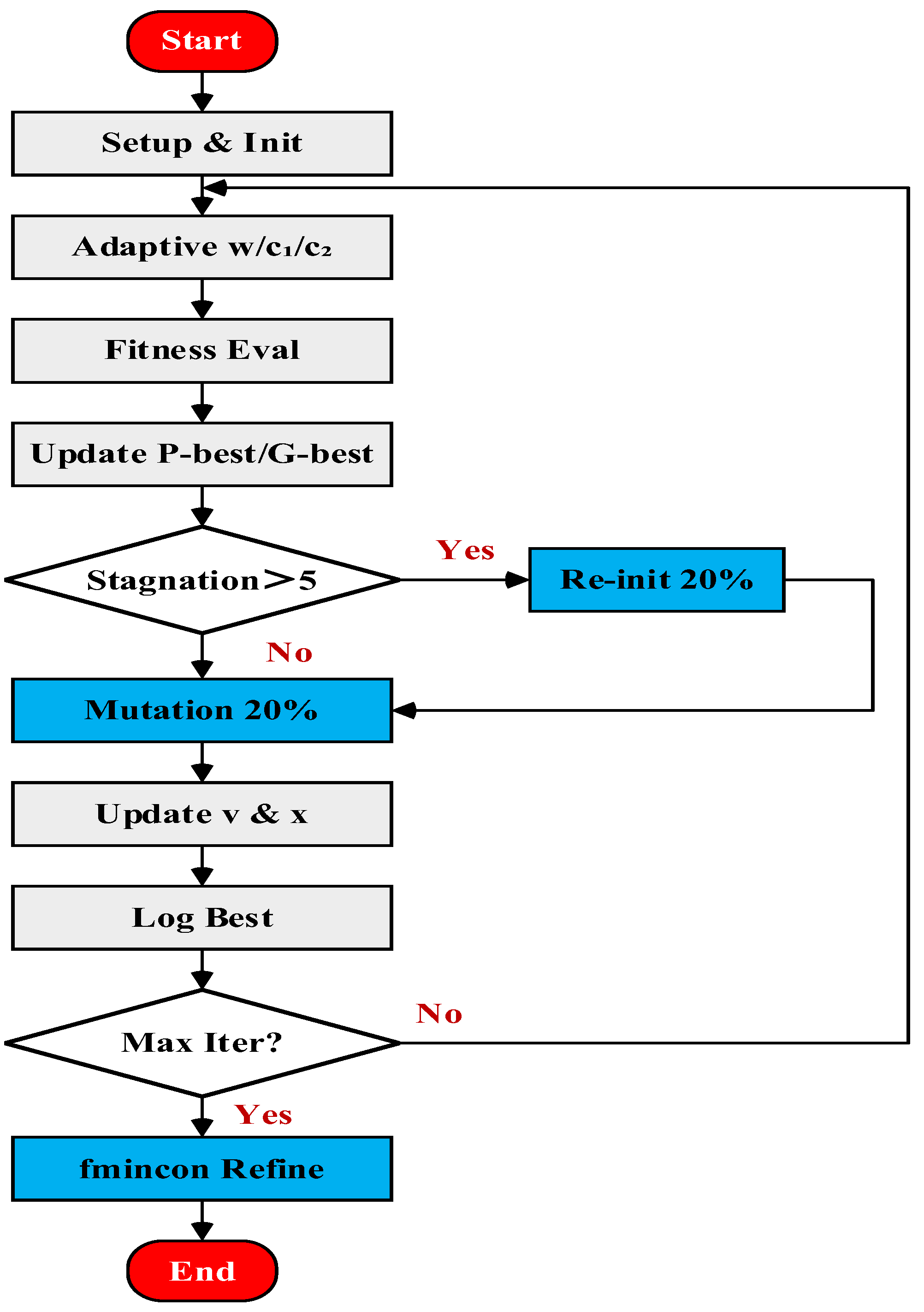
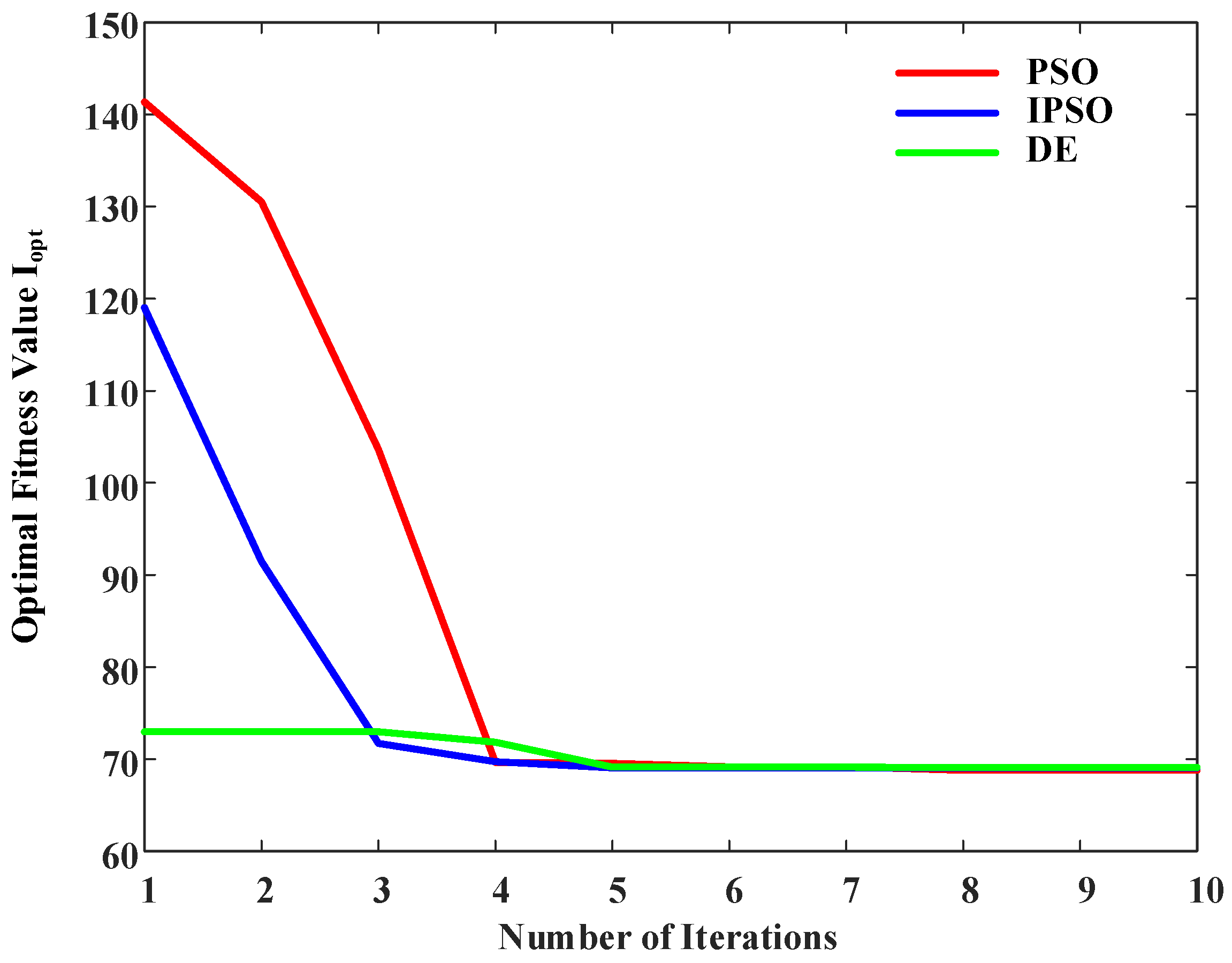
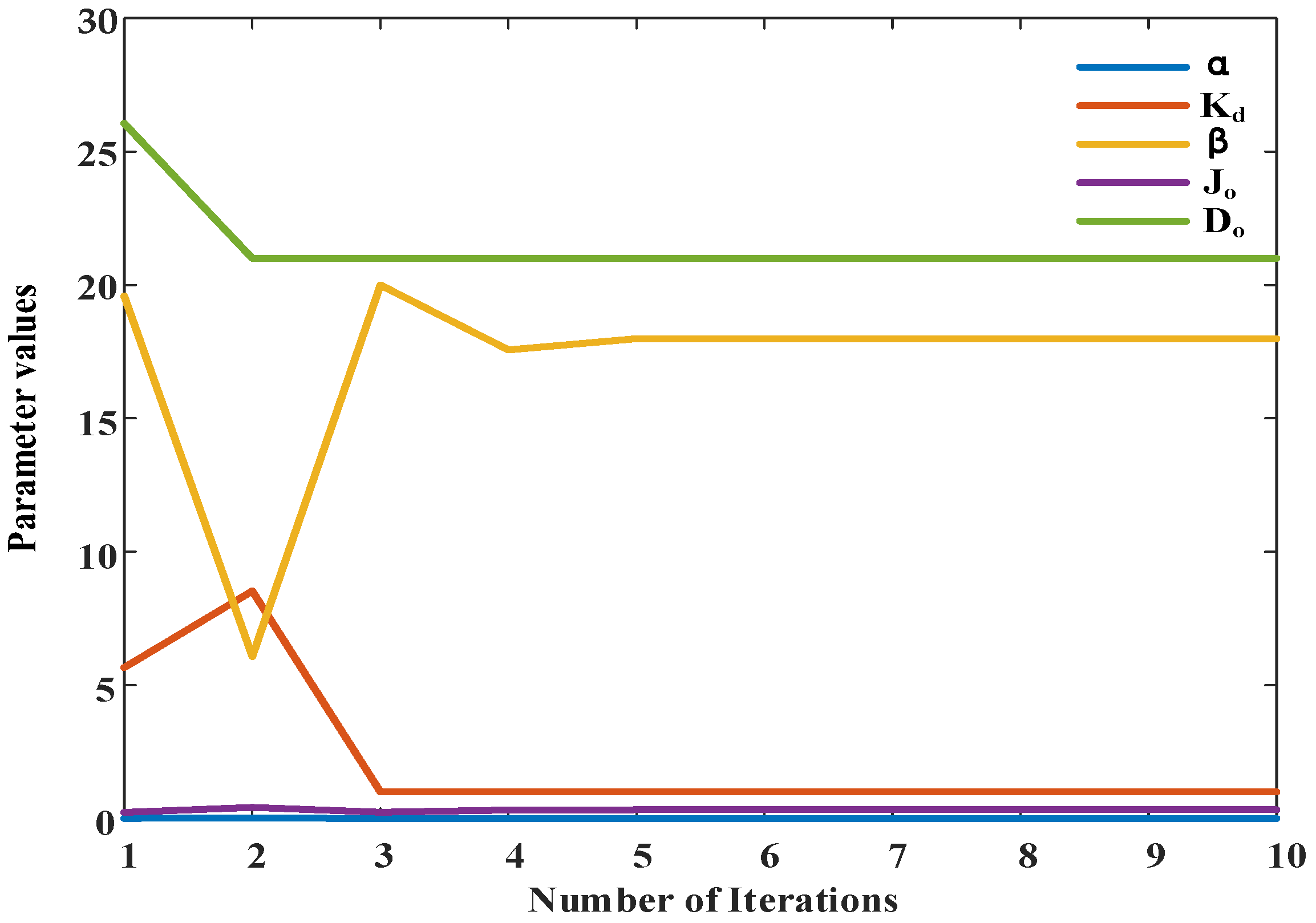
3.2.2. Parameter Optimization Using the Enhanced PSO Algorithm

The proposed adaptive VSG control strategy involves several key parameters to be optimized (e.g., J0, α, D0, Kd, β), all of which significantly influence the dynamic regulation of virtual inertia and damping. Since manual tuning often fails to achieve an optimal trade-off among multiple performance objectives, this work adopts an intelligent optimization approach. Particle Swarm Optimization (PSO) and Differential Evolution (DE) are widely used in control system parameter tuning due to their strong global search capabilities and implementation simplicity. However, standard PSO and DE algorithms often suffer from premature convergence and unstable performance when applied to highly nonlinear, multi-objective, and coupled optimization problems.
To address these issues, this study proposes an enhanced PSO algorithm based on the standard PSO framework. The optimization flowchart of the proposed algorithm is illustrated in Figure 3. Compared to the standard PSO, the proposed algorithm incorporates dynamically adjusted inertia weights and learning factors, random reinitialization in case of stagnation, and local refinement strategies. These enhancements synergistically improve convergence speed, maintain population diversity, and enhance solution accuracy.
The enhanced PSO algorithm begins with the random initialization of particles and their associated parameters. In each iteration, the algorithm adaptively adjusts the inertia weight (w) and learning factors (c1 and c2), evaluates the fitness of each particle, and updates both personal and global best positions. If the global best solution exhibits negligible improvement over several consecutive generations, the population is considered to be stagnating. In such cases, approximately 20% of the particles are randomly reinitialized to restore diversity. If no stagnation is detected, a mutation operation is applied to a non-optimal particle with a fixed probability to continuously introduce new candidate solutions. Subsequently, particle velocities and positions are updated based on a combination of personal best, neighborhood best, and inertia components. The best fitness value and corresponding parameter trajectory are recorded in each generation. If the maximum number of iterations is not reached, the process proceeds to the next generation. Upon completion of all iterations, a local optimizer is employed to refine the current best global solution, thereby achieving a balance between global exploration and convergence precision.
In addition, a comprehensive performance index, Iopt, is adopted in this paper as the optimization objective:
I opt = w 1 f ITAE + w 2 O s + w 3 S T + w 4 P ITAE ,
where fITAE represents the integral of frequency deviation, Os is the maximum frequency overshoot, ST denotes the frequency settling time, PITAE is the integral of active power deviation, and w represents the weighting coefficients assigned to each performance metric. Under identical initial conditions and using the same objective function, the convergence performance of standard PSO, improved PSO, and DE algorithms is evaluated for parameter tuning. The evolution curves of the optimal fitness value Iopt are illustrated in Figure 4.
The improved PSO exhibits a faster initial convergence rate and attains a lower final objective function value compared to the standard PSO and DE algorithms, indicating superior optimization accuracy and global search capability. Moreover, the convergence process is smooth and stable, validating the effectiveness of adaptive weighting, neighborhood-based updating, and mutation mechanisms. Therefore, the improved PSO algorithm is adopted as the optimization tool for tuning the parameters of the exponential inertia and tanh-based damping control strategy.
As shown in Figure 5, the improved PSO algorithm was applied for parameter optimization with a particle population of 30. After 10 iterations, the optimal parameters were obtained as follows: α = 0.001, Kd = 1, β = 17.988, Jo = 0.330, and Do = 21.002. The corresponding optimal objective function value was Iopt = 69.0386.

4. Simulation Verification

To verify the effectiveness of the theoretical analysis and the proposed enhanced adaptive control strategy, a single VSG model was developed in MATLAB/Simulink for simulation analysis. The simulation parameters are listed in Table 1.

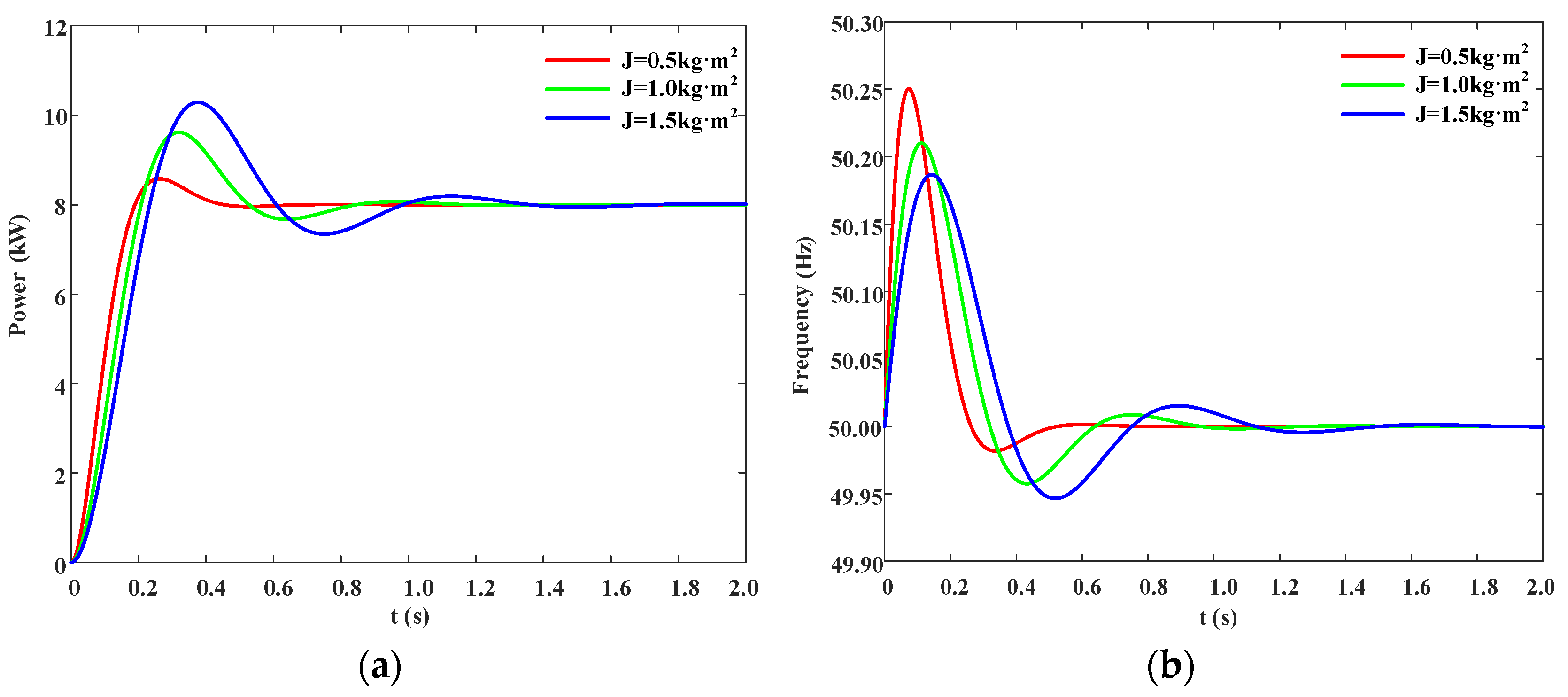
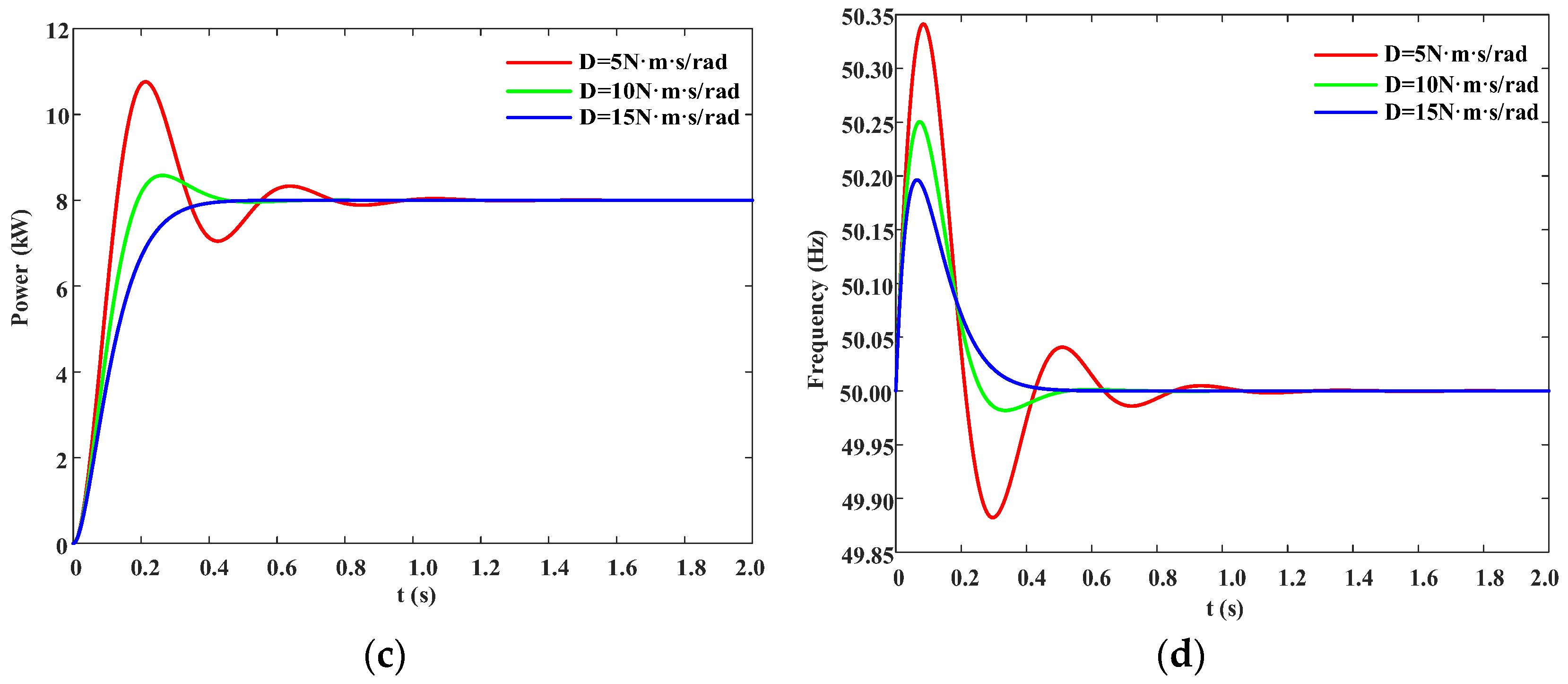
4.1. Validation of Theoretical Analysis

As shown in Equation (6), the virtual inertia J and damping coefficient D have a significant impact on the dynamic response characteristics of the VSG second-order system. Based on the simulation parameters listed in Table 1, the dynamic responses of active output power and frequency under varying values of inertia and damping are obtained by substituting them into Equation (5), as illustrated in Figure 6.
As illustrated in Figure 6a,b, with the damping coefficient fixed, variations in the virtual rotational inertia J exhibit a significant bidirectional coupling effect on the transient electrical performance of the VSG. Numerical results show that as J increases from 0.5 kg·m2 to 1.5 kg·m2, the peak active power injected into the grid rises from 8.8 kW to 10.6 kW, and the steady-state recovery time extends from 0.55 s to 1.20 s, indicating enhanced inertial support capability. Meanwhile, the positive frequency deviation decreases from 0.25 Hz to 0.18 Hz. However, both the negative overshoot and the amplitude of low-frequency oscillations increase, with the frequency settling time extended from 0.60 s to 1.40 s, suggesting that increasing inertia may weaken the damping effect. These results indicate that increasing virtual inertia effectively suppresses initial frequency overshoot, but insufficient damping compensation may slow the attenuation of oscillations and delay dynamic recovery.
As shown in Figure 6c,d, when the virtual rotational inertia is held constant, increasing the damping coefficient D from 5 N·m·s/rad to 15 N·m·s/rad reduces the initial peak active power injected into the grid from approximately 11 kW to 8 kW—a nearly 25% decrease—while secondary oscillations are nearly eliminated. Accordingly, the power curve’s steady-state recovery time shortens from 1.1 s to 0.55 s, indicating that higher damping significantly accelerates energy dissipation. As D increases, the maximum frequency deviation decreases from 0.34 Hz to 0.19 Hz, and the minimum frequency nadir rises significantly. The frequency settling time also shortens from 1.1 s to 0.55 s, demonstrating that higher damping effectively suppresses low-frequency oscillations after inertia injection and accelerates system resynchronization. However, excessive damping also limits the release rate of kinetic energy from the inertia loop, resulting in a slower rise slope and a relatively weakened transient power support capacity. Overall, increasing the damping gain under fixed inertia conditions suppresses overshoot, shortens the oscillation decay period, and enhances system frequency stability margins.

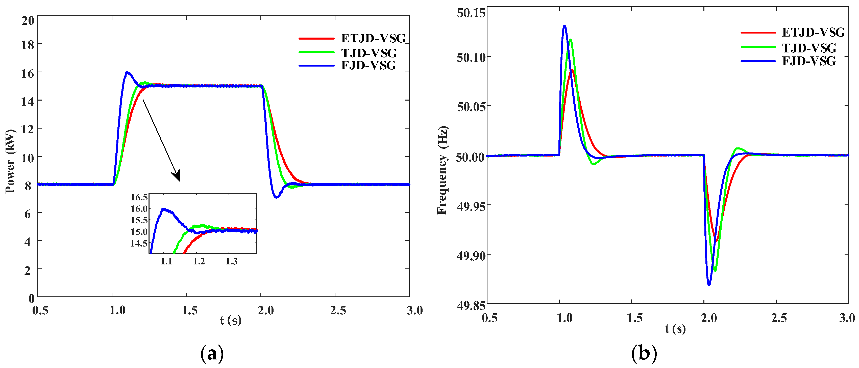
4.2. Validation of Adaptive Control Strategy

To evaluate the proposed adaptive scheme, simulations compare three VSG control methods: (1) traditional fixed-parameter VSG control (FJD-VSG); (2) a segmented adaptive method based on a dual-threshold evaluation of the frequency rate of change dω/dt and frequency deviation Δω (TJD-VSG); and (3) the proposed exponential inertia tuning and tanh-based damping regulation method (ETJD-VSG).

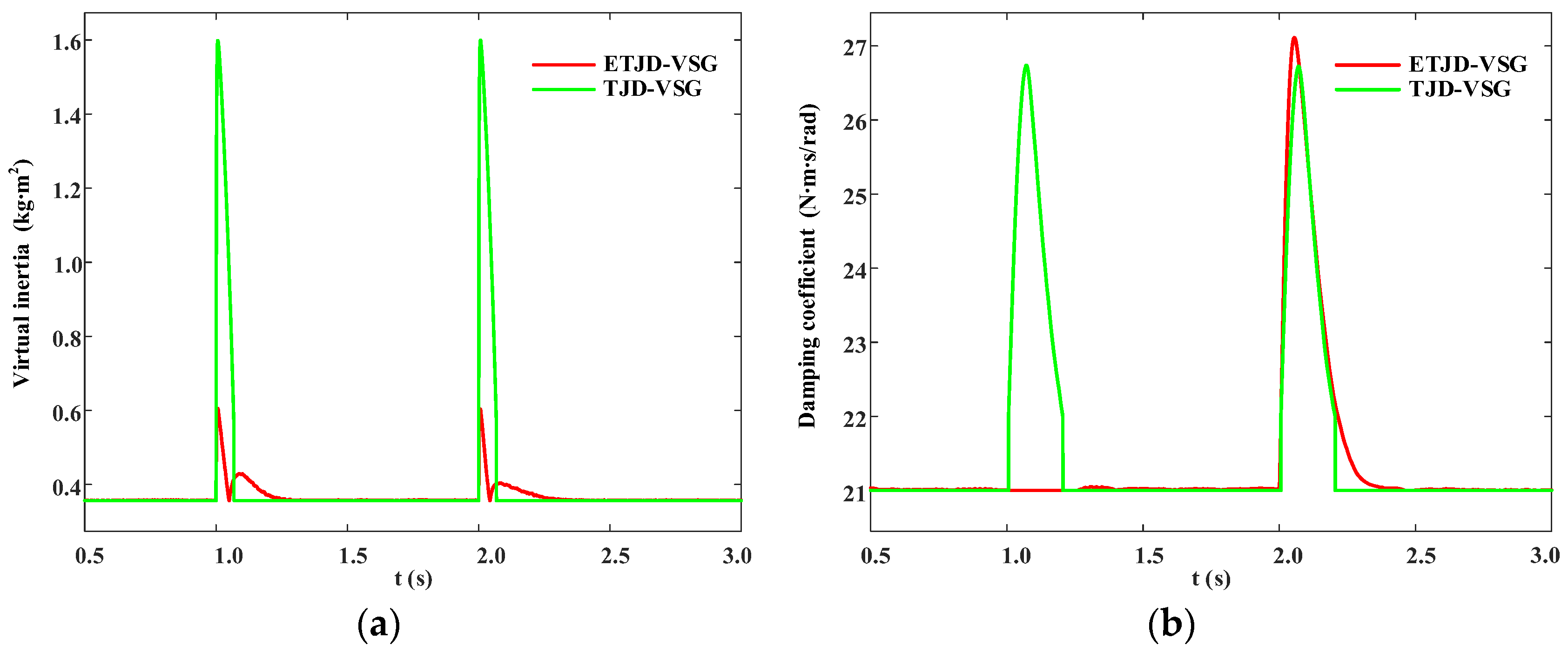
4.2.1. Sudden Change in Active Power Reference of VSG Output

To emulate abrupt changes in active power demand in real-world power systems, a simulation scenario was designed with a total duration of 3 s. At time t = 0 s, the PCC switch is closed, and the VSG is connected to the grid with an initial load of 8 kW. The initial active power reference is set to 8 kW. At t = 1 s, the reference steps up to 15 kW, and at t = 2 s, it returns to 8 kW.
As shown in Figure 7a, the FJD-VSG exhibits a notable overshoot during the power ramp-up stage, reaching approximately 6.7%, and demonstrates poor steady-state tracking performance. Although the TJD-VSG slightly reduces the overshoot, oscillations still occur in the early steady-state phase due to segmented parameter switching. In contrast, the ETJD-VSG effectively suppresses active power overshoot, and the response curve rapidly converges to the reference value. As illustrated in Figure 7b, both FJD-VSG and TJD-VSG exhibit significant frequency deviations during step disturbance. Although TJD-VSG reduces the deviation amplitude to some extent, abrupt changes in both the virtual inertia J and damping coefficient D occur at threshold-switching transitions, causing the frequency peak to remain relatively high. Simulation results confirm that ETJD-VSG significantly reduces both active power overshoot and peak-to-valley frequency deviation compared to FJD-VSG. Specifically, the frequency deviation is reduced by approximately 26.15%, clearly validating the proposed method’s effectiveness in enhancing transient support and improving frequency stability margins.
As shown in Figure 8a,b, the trajectories of virtual inertia and damping reveal fundamental differences in parameter dynamics between the two adaptive control algorithms. The segmented, threshold-based TJD-VSG abruptly raises the virtual inertia J and damping coefficient D to 1.6 kg·m2 and 26.8 N·m·s/rad, respectively, upon reaching the threshold, and then suddenly drops them back to their baseline values. This behavior produces sharp, rectangular-shaped peaks. Although this strategy offers strong inertial and damping support during the initial disturbance phase, it tends to induce control oscillations near the switching thresholds. In contrast, the ETJD-VSG enables the virtual inertia J to increase smoothly to 0.6 kg·m2 during the initial frequency peak and then gradually decrease, driven by the rapid decay of the absolute frequency derivative ω ˙ . A secondary, smaller rise in inertia occurs due to residual frequency oscillations, after which it exponentially returns to its nominal value J0, demonstrating the algorithm’s ability to recognize and respond to residual fluctuations. The damping coefficient D increases smoothly only when Δω > 0, thereby avoiding excessive damping during periods of negative frequency deviation. In summary, the ETJD-VSG strategy effectively eliminates abrupt parameter transitions, striking a balance between strong inertial support during the initial frequency peak and smooth attenuation of subsequent oscillations. This leads to improved transient stability and enhanced control robustness, especially under high-penetration renewable energy integration scenarios.

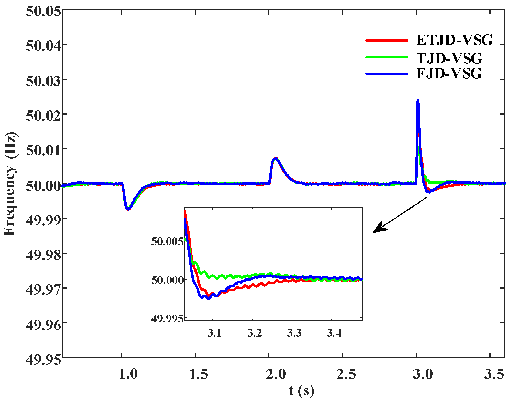
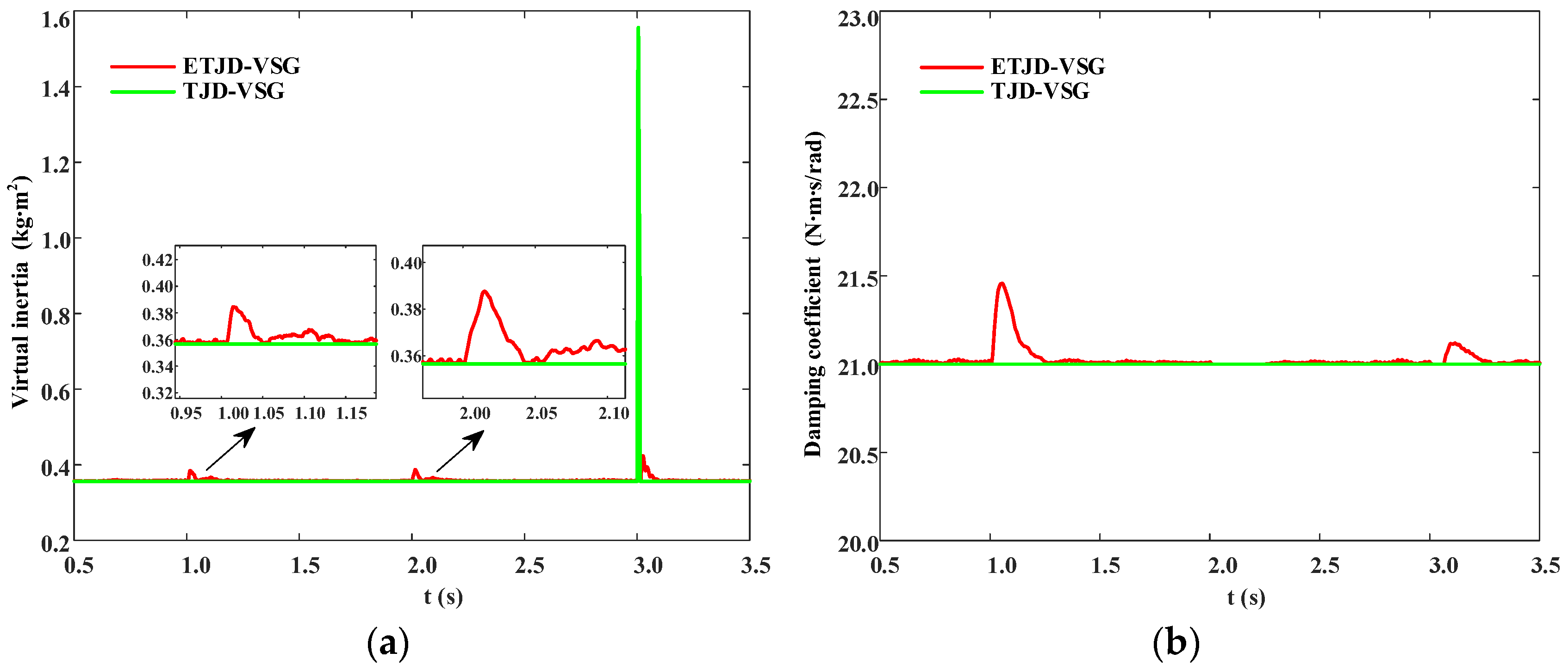
4.2.2. Grid-Connected Condition with Small Load Fluctuations

During normal power system operation, small load-side fluctuations frequently occur. To evaluate the performance of the proposed control strategy under such conditions, a simulation scenario is designed in which the system operates in grid-connected mode with minor variations in load power. Specifically, the initial load is set to 8 kW; at 1 s, an additional 0.4 kW is applied; at 2 s, the load returns to 8 kW; and at 3 s, 0.2 kW is removed. The system’s behavior is observed over a 4 s window. As shown in Figure 9, all three VSG control strategies maintain comparable frequency stability under small routine fluctuations.
As illustrated in Figure 10a,b, the segmented threshold-based TJD-VSG displays a significant limitation in adapting to small disturbances. Because both the virtual inertia and damping are activated only when hard thresholds are crossed, the virtual inertia J remains fixed at its nominal value J0 during minor load changes at 1 s and 2 s, and only exhibits a sudden jump to 1.6 kg·m2 during the load reduction at 3 s, followed by a rapid drop. Meanwhile, the damping coefficient D remains constant at D0 throughout the simulation, providing no additional support to suppress small frequency deviations. In contrast, under the ETJD-VSG control strategy, the virtual inertia increases smoothly, reaching a peak value of only 0.45 kg·m2 during small load fluctuations. The damping control mechanism, based on the tanh function, is designed to respond only to positive frequency deviations. At 2 s, the frequency deviation becomes negative, resulting in no significant change in the damping coefficient.

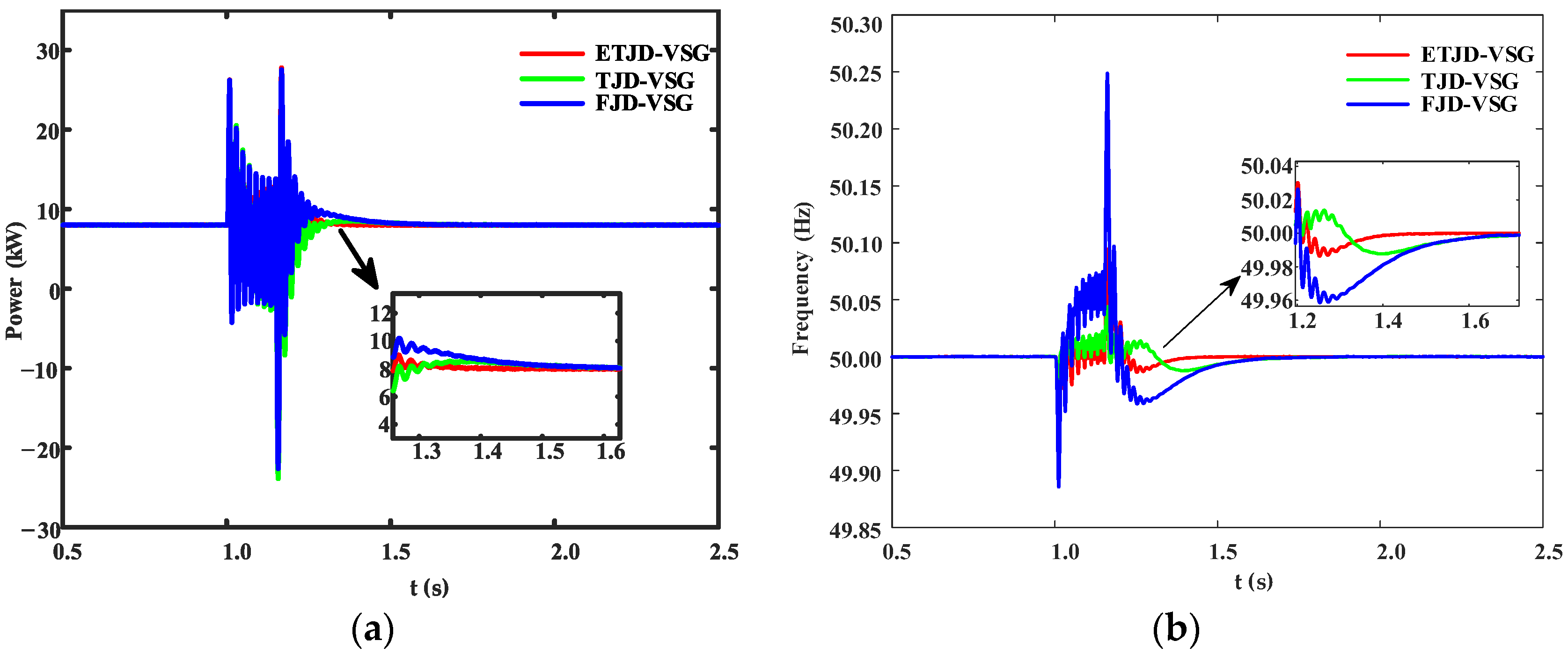
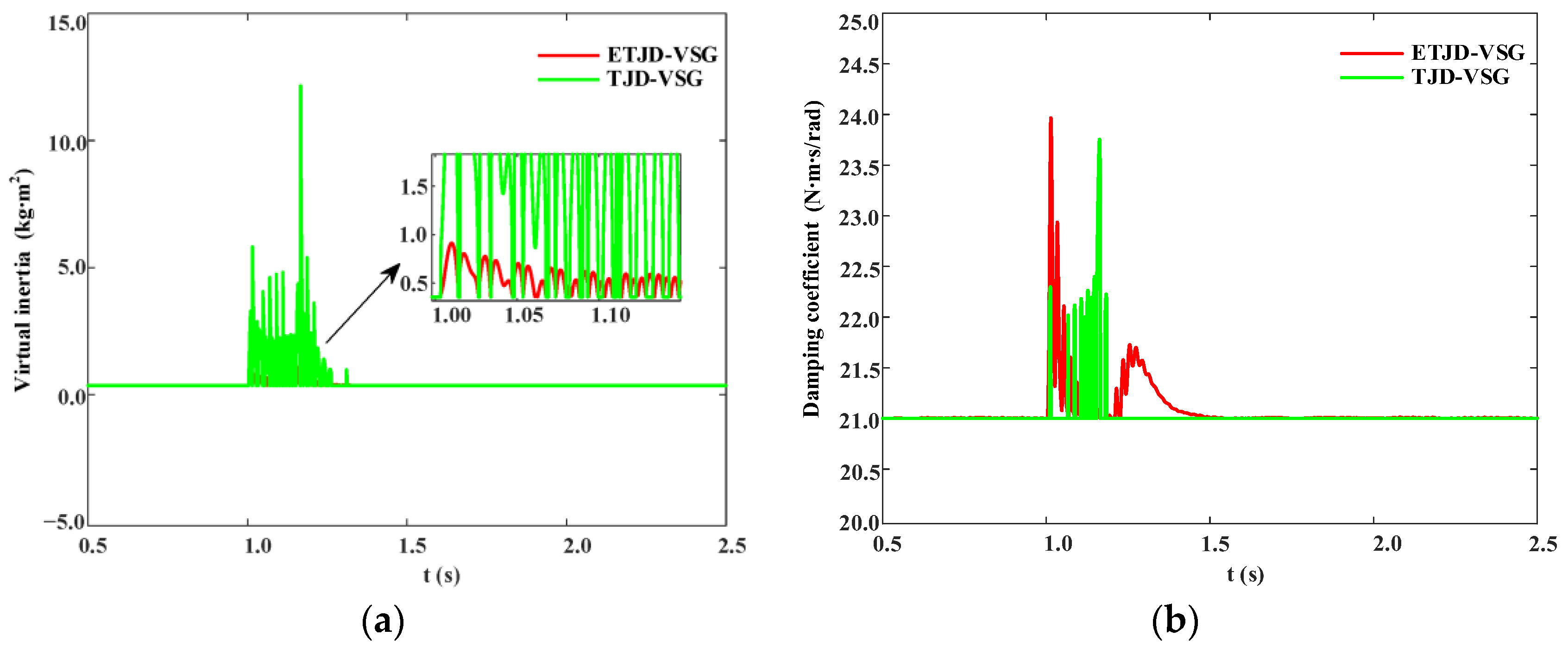
4.2.3. Grid-Side Single-Phase Fault Condition

To further evaluate the transient response capability of the proposed VSG control strategy under grid disturbances, a grid-side single-phase-to-ground fault scenario is simulated in this subsection. Specifically, a 150 ms single-phase short-circuit fault is introduced at 1.0 s and cleared at 1.15 s. Compared to symmetrical three-phase faults, single-phase faults occur more frequently in practical distribution networks and thus provide a representative test case for evaluating controller robustness. This test aims to assess the VSG’s ability to maintain power stability and suppress oscillations under asymmetric fault conditions.
As shown in Figure 11a, all three control strategies deviate abruptly from the steady-state output of 8 kW and enter high-frequency oscillations following fault clearance at t = 1.15 s. However, the oscillation amplitude and decay rate differ significantly among the strategies. During the transient period, the FJD-VSG exhibits a peak-to-valley fluctuation of approximately 50.19 kW. The TJD-VSG slightly reduces this fluctuation to 50.13 kW. In contrast, the ETJD-VSG further reduces the fluctuation to 48.45 kW, representing reductions of 3.47% and 3.35% compared to FJD-VSG and TJD-VSG, respectively. Moreover, ETJD-VSG exhibits the fastest damping performance after fault clearance, with the oscillation envelope settling within 0.31 s. These results demonstrate that ETJD-VSG, through coordinated flexible inertia injection and nonlinear damping, effectively suppresses active power surges and significantly accelerates power resynchronization.
As illustrated in Figure 11b, the FJD-VSG exhibits the largest frequency fluctuation during the transient phase, with a peak-to-valley difference of approximately 0.36 Hz. The TJD-VSG and the proposed ETJD-VSG produce similarly smaller peak-to-valley variations. After fault clearance, FJD-VSG exhibits high-frequency beating between 1.15 and 1.25 s, characterized by gradually diminishing amplitude but prolonged duration. TJD-VSG shows a smaller high-frequency component; however, a “hump-shaped” secondary overshoot appears between 1.25 and 1.35 s. In contrast, ETJD-VSG converges monotonically without any additional overshoot. ETJD-VSG significantly shortens the frequency recovery time and confines the peak-to-peak frequency deviation within 0.15 Hz, confirming the effectiveness of the coordinated exponential inertia and nonlinear damping regulation.
As shown in Figure 12a,b, the virtual inertia J and damping coefficient D exhibit significantly different dynamic trajectories under the two adaptive strategies following the onset of the single-phase fault. Under the TJD-VSG scheme, J rises abruptly from its base value J0 to approximately 6 kg·m2 and then undergoes repeated oscillations, while D exhibits over twenty sharp spikes, peaking at around 23.7 N·m·s·rad−1. These large values of dJ/dt and dD/dt inject high-frequency torque pulses into the electromagnetic path, directly causing the “hump-shaped” secondary overshoot observed around 1.25 s in Figure 11b. In contrast, under the ETJD-VSG scheme, the maximum virtual inertia reaches only 1.1 kg·m2, and the damping coefficient increases smoothly to approximately 24 N·m·s·rad−1 before decaying exponentially. The entire process remains continuously differentiable and free of abrupt transitions. Therefore, ETJD-VSG ensures adequate transient support while avoiding the shock effects induced by stepwise changes inherent in threshold-based methods, thereby shortening the frequency resynchronization time. These results confirm the effectiveness and engineering applicability of the coordinated exponential inertia and nonlinear damping regulation.

5. Conclusions

This paper addresses the reduction in system inertia and damping associated with large-scale renewable energy integration by proposing ETJD-VSG, a continuously adaptive VSG control strategy that integrates exponential inertia injection with a tanh-shaped nonlinear damping mechanism. The strategy is parameterized using an improved particle swarm optimization (PSO) algorithm guided by a composite fitness index. Simulation results confirm three principal findings. (i) Under severe power step disturbances, ETJD-VSG limits the frequency peak-to-nadir deviation to 0.17 Hz, representing a reduction of approximately 33.95% compared to the fixed parameter VSG. (ii) During small, stochastic load variations, it avoids the parameter dead-band and switching ripples observed in dual-threshold controllers, resulting in smoother inertia–damping trajectories and the complete elimination of secondary oscillations. (iii) Under grid-side single-phase faults, ETJD-VSG suppresses active power surges by 3–4% and accelerates resynchronization to within 0.31 s.
Beyond numerical improvements, ETJD-VSG requires only frequency and power measurements, introduces no hard thresholds, and is readily implementable on the DSP/FPGA hardware commonly used in grid-forming inverters—features that lower deployment barriers for wind–solar–storage systems and islanded microgrids.
Nevertheless, two limitations should be acknowledged: (1) the current results are based solely on detailed simulations without hardware validation, and (2) the coordination among multiple inverters has not been investigated. Future work will focus on hardware-in-the-loop (HIL) experiments, field deployment in weak-grid environments, and hierarchical control extensions that integrate the proposed controller with battery or flywheel storage systems for system-wide inertia scheduling.

Author Contributions

Conceptualization: H.P. and K.M.; methodology: H.P., K.M. and H.L.; software and validation: Y.L.; data curation: Z.L. and L.J.; formal analysis: H.P. and K.M.; writing—original draft: H.P.; writing—review and editing: K.M. and H.L.; supervision and project coordination: Y.L., Z.L. and L.J. All authors have read and agreed to the published version of the manuscript.

Funding

This research was supported by the National Key Research and Development Program of China (Grant No. 2023YFB2405905; Funder: Yongjiang Liu), and by Huaneng New Energy Co., Ltd. under the project “Research and Application of Key Equipment and Control Strategies Adapted to New Energy Power Grids” (Grant No. HNKJ24-H117). The article processing charge (APC) was funded by Inner Mongolia Power (Group) Co., Ltd.

Data Availability Statement

The original contributions presented in this study are included in this article; further inquiries can be directed to the corresponding author.

Conflicts of Interest

Author Yongjiang Liu was employed by the company Inner Mongolia Power (Group) Co., Ltd. Author Zhi Li and Ligang Jiang was employed by the company Huaneng Wulatezhongqi New Energy Power Generation Co., Ltd. The remaining authors declare that the research was conducted in the absence of any commercial or financial relationships that could be construed as a potential conflict of interest.

References

  1. Wang, Y.; Jin, T.; Weng, J. Virtual Synchronous Generator with Improved Adaptive Control of Rotational Inertia. Chin. Meas. Test 2025, 1, 1–6. Available online: http://kns.cnki.net/kcms/detail/51.1714.TB.20240325.1223.010.html (accessed on 7 May 2025).
  2. Khajehoddin, A.S.; Karimi-Ghartemani, M.; Ebrahimi, M. Grid-Supporting Inverters with Improved Dynamics. IEEE Trans. Ind. Electron. 2019, 66, 3655–3667. [Google Scholar] [CrossRef]
  3. Linbin, H.; Huanhai, X.; Zhen, W. Damping Low-Frequency Oscillations Through VSC-HVdc Stations Operated as Virtual Synchronous Machines. IEEE Trans. Power Electron. 2019, 34, 5803–5818. [Google Scholar]
  4. Lan, Z.; Liu, Z.; He, D. Active Power Oscillation Suppression Strategy for VSG Parallel Systems Based on Transient Electromagnetic Power Compensation. Power Syst. Technol. 2023, 47, 23–33. [Google Scholar]
  5. Chao, K.; Miao, S.; Liu, Z. Microgrid Stability Analysis Based on Virtual Synchronous Generator Control. Prot. Control Mod. Power Syst. 2019, 47, 9–16. [Google Scholar]
  6. Li, C.; Yang, Y.; Cao, Y.; Wang, L.; Blaabjerg, F. Frequency and Voltage Stability Analysis of Grid-Forming Virtual Synchronous Generator Attached to Weak Grid. IEEE J. Emerg. Sel. Top. Power Electron. 2022, 10, 2662–2671. [Google Scholar] [CrossRef]
  7. Zhu, X.; Liu, Y.; Liu, S. Adaptive Control Strategy of VSG Based on Variable Universe Fuzzy Control. Distrib. Energy 2023, 8, 19–28. [Google Scholar]
  8. Li, J.; Wen, B.; Wang, H. Adaptive Virtual Inertia Control Strategy of VSG for Microgrid Based on Improved Bang-Bang Control Strategy. IEEE Access 2019, 7, 39509–39514. [Google Scholar] [CrossRef]
  9. Li, Z.; Yang, M.; Zhang, J. Cooperative Adaptive Control of VSG Inertia and Damping. J. Electr. Power Syst. Autom. 2023, 35, 36–43. [Google Scholar]
  10. Liu, J.; Miura, Y.; Ise, T. Fixed-Parameter Damping Methods of Virtual Synchronous Generator Control Using State Feedback. IEEE Access 2019, 7, 99177–99190. [Google Scholar] [CrossRef]
  11. Wang, S.; Xie, Y. Virtual Synchronous Generator Control Strategy Based on Improved Damping and Angular Frequency Deviation Feedforward. Energies 2023, 16, 5635. [Google Scholar] [CrossRef]
  12. Gurski, E.; Kuiava, R.; Perez, F.; Benedito, R.; Damm, G. A Novel VSG with Adaptive Virtual Inertia and Adaptive Damping Coefficient to Improve Transient Frequency Response of Microgrids. Energies 2024, 17, 4370. [Google Scholar] [CrossRef]
  13. Liu, P.; Zheng, K.; Zhu, J. Secondary Frequency Control of Islanded Microgrids Considering Load Dynamic Variations. J. Electron. Meas. Instrum. 2024, 38, 213–224. [Google Scholar]
  14. Zhang, M.; Zhao, T.; Zhu, A. Control Strategy of Virtual Synchronous Generator Based on Current Model Prediction. Mach. Electron. 2023, 41, 63–69. [Google Scholar]
  15. Kang, X.; Huang, W.; Zhou, G. Deep Reinforcement Learning-Based Parameter Self-Tuning Control Strategy for VSG. Energy Rep. 2022, 8, 219–226. [Google Scholar]
  16. Guo, J.; Fan, Y. Adaptive Control Strategy of VSG Parameters Based on Improved Particle Swarm Optimization. J. Electr. Mach. Control 2022, 26, 90–98. [Google Scholar]
  17. Grover, H.; Sharma, S.; Verma, A.; Hossain, M.J.; Kamwa, I. Adaptive Parameter Tuning Strategy of VSG-Based Islanded Microgrid under Uncertainties. In Proceedings of the IEEE International Conference on Sustainable Energy and Future Electric Transportation (SEFET), Hyderabad, India, 31 July–3 August 2024; pp. 1–6. [Google Scholar]
  18. Zhao, N.; Qiao, P.; Zhou, P. Adaptive Control Strategy of VSG Parameters Based on Improved Grey Wolf Algorithm. Power Sci. Eng. 2024, 40, 33–43. [Google Scholar]
  19. Yang, Y.; Liu, C.; Lai, S.K. Frequency-Dependent Equivalent Impedance Analysis for Optimizing Vehicle Inertial Suspensions. Nonlinear Dyn. 2025, 113, 9373–9398. [Google Scholar] [CrossRef]
  20. Wu, X.; Li, W.D.; Li, Z.W. Active Frequency-Response Optimization Control Strategy Considering Electrochemical Energy Storage under Large Disturbances. Autom. Electr. Power Syst. 2023, 47, 118–127. (In Chinese) [Google Scholar]
  21. Zhou, T.; Xiang, Y.J.; Du, K.K. Review of Coordinated Control Technology of Wind Turbine and Energy Storage Participating in Grid Frequency Regulation. Zhejiang Electr. Power 2024, 43, 45–55. (In Chinese) [Google Scholar]
  22. Shi, R.; Lan, C.; Dong, Z. An Active Power Dynamic Oscillation Damping Method for the Grid-Forming Virtual Synchronous Generator Based on Energy Reshaping Mechanism. Energies 2023, 16, 23. [Google Scholar] [CrossRef]
  23. Liu, W.; Shi, R.; Zhou, Q. Adaptive Optimization Strategy for VSG Parameters in Energy Storage System Based on BP Neural Network. Electron. Meas. Technol. 2024, 47, 42–49. [Google Scholar]
  24. EN 50549-1:2019; Requirements for Generating Plants to Be Connected in Parallel with Distribution Networks—Part 1: Connection to a LV Distribution network—Generating Plants up to and Including Type B. CENELEC—European Committee for Electrotechnical Standardization: Brussels, Belgium, 2025. Available online: https://www.en-standard.eu/ (accessed on 15 July 2025).
Figure 1. Circuit topology and control scheme of the VSG.
Energies 18 03822 g001
Figure 2. Small−signal model of the VSG active power closed loop.
Energies 18 03822 g002
Figure 3. Optimization flowchart of the improved PSO algorithm.
Energies 18 03822 g003
Figure 4. Convergence curves of the three algorithms.
Energies 18 03822 g004
Figure 5. Variation curves of each parameter.
Energies 18 03822 g005
Figure 6. Impact of different parameters on system output responses. (a) Active power response curves of the VSG under different virtual inertia values (D = 10 N·m·s/rad). (b) Frequency response curves of the VSG under different virtual inertia values (D = 10 N·m·s/rad). (c) Active power response curves of the VSG under different damping coefficients (J = 0.5 kg·m2). (d) Frequency response curves of the VSG under different damping coefficients (J = 0.5 kg·m2).
Energies 18 03822 g006aEnergies 18 03822 g006b
Figure 7. System response under a sudden change in active power reference. (a) Comparison of system active power output; (b) comparison of system frequency response.
Energies 18 03822 g007
Figure 8. Parameter variation under active power command step change. (a) Virtual inertia J; (b) damping coefficient D.
Energies 18 03822 g008
Figure 9. Frequency variation under small load fluctuations in grid-connected operation.
Energies 18 03822 g009
Figure 10. Parameter variation under small load fluctuations in grid-connected operation. (a) Virtual inertia J; (b) damping coefficient D.
Energies 18 03822 g010
Figure 11. System response under grid-side single-phase fault. (a) Comparison of system active power output; (b) comparison of system frequency response.
Energies 18 03822 g011
Figure 12. Parameter variation under grid-side single-phase fault. (a) Virtual inertia J; (b) damping coefficient D.
Energies 18 03822 g012
Table 1. Simulation parameters of the VSG.
ParametersValuesParametersValues
Udc/V800.00α0.001
Lf/mH5.00β17.99
Rf0.10Kd1.00
Cf/μF30.00Kj_min0.20
Lg/mH0.20Kj_max1.00
Rg0.10J0/(kg∙m2)0.33
ω0/(rad/s)314.00D0/(N∙m∙s/rad)21.002
Disclaimer/Publisher’s Note: The statements, opinions and data contained in all publications are solely those of the individual author(s) and contributor(s) and not of MDPI and/or the editor(s). MDPI and/or the editor(s) disclaim responsibility for any injury to people or property resulting from any ideas, methods, instructions or products referred to in the content.

