Article

Analysis of Heat Transfer and Fluid Flow in a Solar Air Heater with Sequentially Placed Rectangular Obstacles on the Fin Surface

1
Department of Refrigeration and Air-Conditioning Engineering, Chonnam National University, Yeosu 59626, Republic of Korea
2
Department of Mechanical Engineering, Ulsan National Institute of Science and Technology, Ulsan 44919, Republic of Korea
*
Author to whom correspondence should be addressed.
Energies 2025, 18(14), 3811; https://doi.org/10.3390/en18143811
Submission received: 22 June 2025 / Revised: 14 July 2025 / Accepted: 16 July 2025 / Published: 17 July 2025
(This article belongs to the Special Issue Solar Energy and Resource Utilization—2nd Edition)

Abstract

A solar air heater (SAH) converts solar energy into heated air without causing environmental pollution. It features a low initial cost and easy maintenance due to its simple design. However, owing to air’s poor thermal conductivity, its thermal efficiency is relatively low compared to that of other solar systems. To improve its thermal performance, previous studies have aimed at either enlarging the heat transfer surface or increasing the convective heat transfer coefficient. In this study, a novel SAH with fins and sequentially placed obstacles on the fin surface—designed to achieve both surface extension through a finned channel and enhancement of the heat transfer coefficient via the obstacles—was investigated using computational fluid dynamics analysis. The results confirmed that the obstacles enhanced heat transfer performance by up to 2.602 times in the finned channel. However, the obstacles also caused a pressure loss. Therefore, the thermo-hydraulic performance was discussed, and it was concluded that the obstacles with a relative height of 0.12 and a relative pitch of 10 yielded the maximum THP values among the investigated conditions. Additionally, correlations for the Nusselt number and friction factor were derived and predicted the simulation values with good agreement.

1. Introduction

As environmental pollution and energy depletion issues arise due to the significant increase in fossil fuel usage, interest in transitioning from traditional energy sources to renewable energy is growing worldwide. A solar air heater (SAH) is a renewable energy system that converts solar irradiance into heated air without causing environmental pollution. This system offers advantages in terms of initial cost, manufacturing, and maintenance owing to its uncomplicated configuration relative to other solar conversion devices. It can be utilized for several purposes, including space heating, food drying, pre-heating for industrial processes, and more [1]. However, the poor thermal conductivity of air decreases the convective heat transfer coefficient between the absorber and the flowing air in an SAH, thereby causing relatively lower thermal efficiency compared to other types of solar conversion systems [2,3]. Therefore, many studies have been conducted to address this issue.
One effective approach to augment the thermal performance of an SAH is to extend the surface area of the heat transfer in its air channel. Pakdaman et al. [4] integrated an SAH with longitudinal fins and experimentally evaluated its performance under natural convection. Their research showed that the inclusion of fins led to a notable increase in the SAH’s performance. Fudholi et al. [5] compared double-pass SAHs with and without fins through numerical analysis and concluded that inserting fins effectively improves the thermal efficiency of an SAH. Priyam and Chand [6] investigated a wavy-finned SAH using a numerical method and confirmed that an SAH with a wavy fin achieved higher thermal efficiency compared to an SAH without a wavy fin. Kabeel et al. [7] experimentally assessed the daily thermal performance of a finned SAH with various fin heights. Their study revealed that higher fin heights led to higher efficiency. Chand et al. [8] suggested an SAH with louvered fins and conducted an experimental study. Their study concluded that incorporating louvered fins improved the thermal efficiency of a cumulative SAH by up to 106.7% compared to an SAH without fins. Karwa [9] established a numerical model of a finned SAH with a rectangular air flow channel and demonstrated that their SAH had about 31% higher thermal efficiency relative to the conventional SAH. Vengadesan et al. [10] proposed an SAH with discontinuous V-corrugated fins and rectangular tubes and found that the proposed SAH performed better than a conventional SAH, despite the increased pressure penalty. Elakrout et al. [11] compared a double-pass SAH with three different fin configurations—vertical, parallel, and opposed—using computational fluid dynamics (CFD). Their study indicated that the configuration of the fin provided the highest thermal performance among the fins investigated. In addition to these studies, various fin types, such as offset strip fins [12], C-shaped fins [13], and double triangular fins [14], have also been investigated.
Another method is to boost the heat transfer coefficient at the heated wall through the incorporation of ribs, obstacles, baffles, etc. [15]. Yadav and Bhagoria [16,17,18] demonstrated, through CFD analysis, that installing circular, triangular, or square ribs on the heated wall can effectively enhance heat transfer performance. Gawande et al. [19] analyzed heat transfer augmentation due to reverse L-shaped ribs. Their research found that the ribs improved the heat transfer coefficient at the heated wall by up to 2.827 times. Singh and Singh [20] investigated an SAH with square wave-profiled transverse ribs of various heights and pitches, and demonstrated that the ribs could improve heat transfer by up to 2.14 times. Singh et al. [21] experimentally and numerically evaluated the thermal behavior of an SAH with multiple broken transverse ribs. Their study demonstrated that the proposed ribs achieved maximum thermal enhancement by 3.24 times while increasing the pressure drop by 3.85 times. Kumar and Goel [22] performed a CFD analysis to evaluate an SAH with various rib shapes in a triangular airflow channel. Their research indicated that backward-chamfered rectangular ribs outperformed ribs of other shapes. Boussouar et al. [23] analyzed an SAH equipped with perforated baffles and indicated that incorporating baffles with holes enhances heat transfer performance while reducing pressure drop. Kumar et al. [24] evaluated an SAH with polygonal ribs using CFD analysis for various rib pitches and Reynolds numbers ( R e ), and reported that the polygonal rib enhanced thermal performance for all fin pitches and R e compared to an SAH without ribs. In addition, various designs, such as an SAH with plus-shaped baffles [25], dimples [26], triangular blocks [27], wavy ribs [28], one-eighth sphere vortex generators [29], and rotating cylindrical turbulators [30], have also been evaluated. Further studies can be found in comprehensive review articles [3,15,31,32,33,34].
So far, many studies have been conducted, as revealed in the aforementioned literature review. However, most of these studies have been conducted either by incorporating extended surfaces or by enhancing the convective heat transfer coefficient. If obstacles are combined with a finned surface, the heat transfer coefficient at the finned surface can be improved while simultaneously extending the heat transfer surface area. Accordingly, in a previous study, the authors demonstrated that attaching obstacles to the finned channel improved heat transfer performance [35]. In this study, the installation locations of the base and side obstacles were restricted to the same position. Hence, in a further study, it was confirmed that the sequential installation of obstacles along the finned surface yielded the highest thermo-hydraulic performance [36]. However, the heat transfer and fluid flow characteristics can vary considerably depending on the obstacle height and pitch. Despite this, the effects of these geometric parameters have not yet been thoroughly analyzed for sequentially placed obstacles in a finned air channel.
To fill this research gap, this study investigates thermal and flow characteristics in a fin channel of an SAH with sequentially placed rectangular obstacles using CFD analysis. Heat transfer enhancement and pressure loss were evaluated for various obstacle heights and pitches under different R e values. The thermo-hydraulic performance was also assessed to account for both the improvement in heat transfer and the associated pressure drop. Additionally, correlations for the Nusselt number ( N u ) and friction factor ( f ) were derived from the simulation results as dependent variables of geometric conditions and R e . The objective of this study is to explore how the height and pitch of sequentially placed obstacles affect heat transfer and pressure loss, and to identify the geometric conditions that yield the highest performance.

2. Methodology

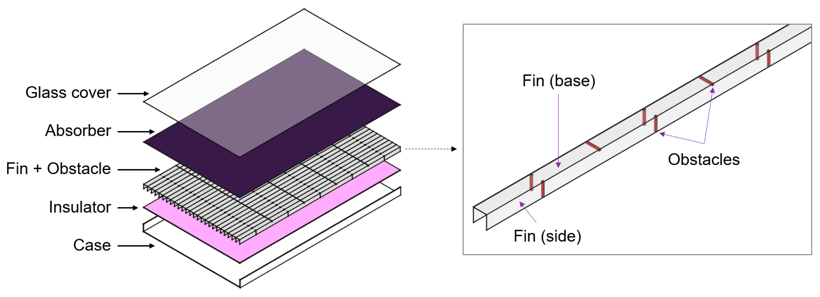
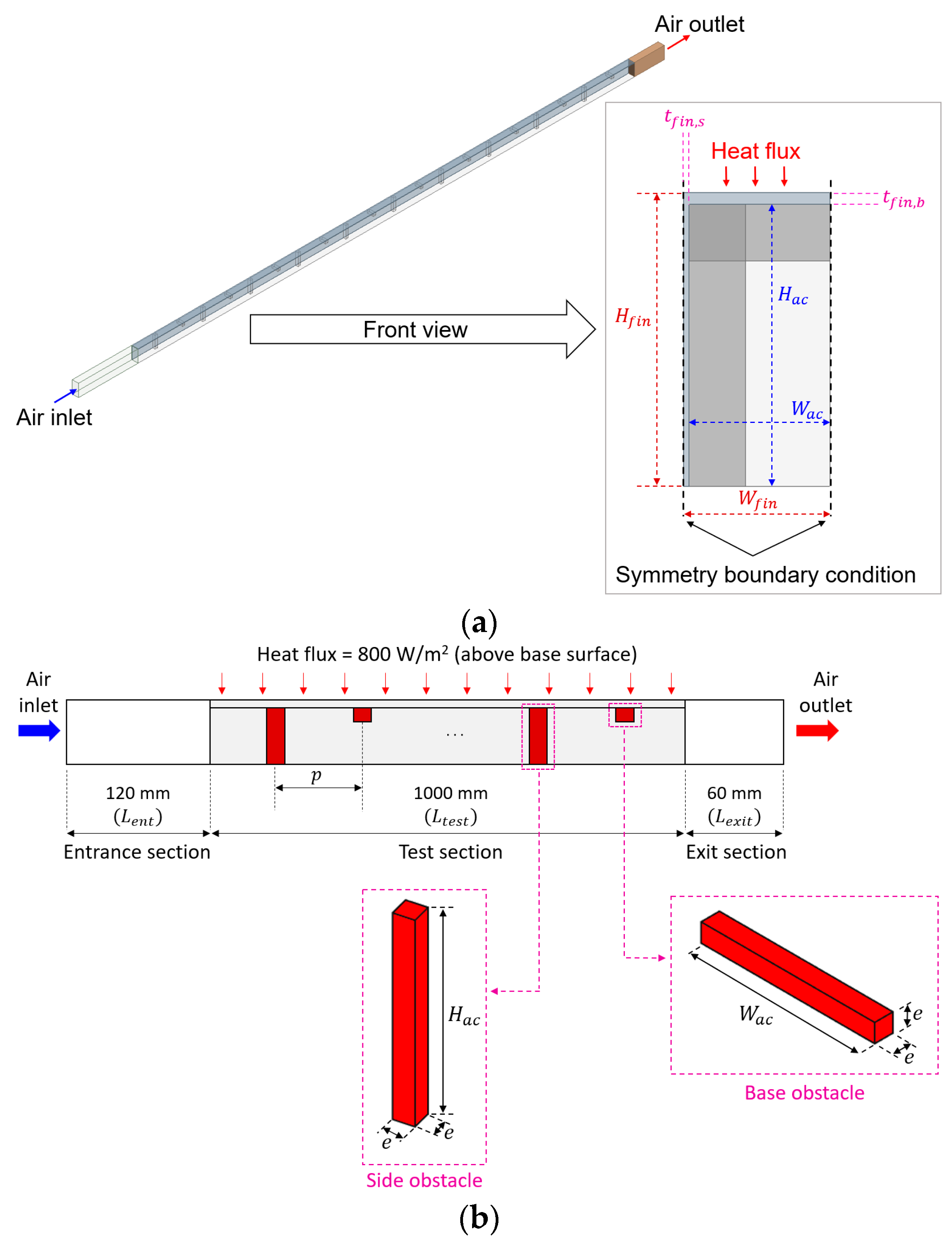
2.1. Description of the Model

Figure 1 presents a schematic illustrating an SAH featuring sequentially placed obstacles in the finned air channel. The absorber is in contact with the base plate of the fin. The obstacles are sequentially placed on both the upper side and vertical faces of the fin, boosting convective heat transfer along the fin surfaces.
This study aims to analyze the thermal and fluid flow characteristics with different configurations of obstacle height and pitch. Accordingly, one of these finned channels was selected for analysis. A symmetric condition was implemented along the mid-plane of the selected finned channel and the fin’s lateral surface to minimize the simulation domain. Figure 2 illustrates the computational domain developed using the commercial software ANSYS Fluent 2023 R1, including the specified boundary conditions. The computational domain consists of an entrance section which is 120 mm long, a test section which is 1000 mm long, and an exit section which is 60 mm long. The finned air channel and obstacles are located in the test section. Four different relative heights, ranging from 0.04 to 0.28, and four different relative pitches, ranging from 10 to 34, were used, selected based on related previous research [17,20,25,28], while the width and height of the finned channel remained fixed. Five different R e values, varying from 3000 to 15,000, were used for each configuration. As a result, a total of 80 cases were investigated. Table 1 summarizes the values of the geometric conditions for the investigated computational domain.

2.2. Boundary Conditions and Solution Method

As boundary conditions, a constant velocity inlet with an air temperature of 300 K was specified. At the outlet, a constant pressure of 101.325 kPa was applied [19,22,28]. A heat flux of 800 W/m2 was applied to the top surface of the base fin, which has commonly been used in similar studies [3,31,37,38], while the remaining walls were treated as adiabatic. Consequently, the air introduced at 300 K was heated in the finned air channel. Additionally, a no-slip condition was applied to all solid surfaces. Table 2 summarizes the boundary conditions adopted in the simulation.
To solve the computational domain, the commercial software ANSYS Fluent was used. The continuity, momentum, energy, and turbulence equations were solved using the aforementioned boundary conditions, assuming steady-state and incompressible flow. To link the velocity and pressure, a coupled algorithm was adopted. The governing equations were discretized using a second-order upwind scheme. The convergence criteria were set to 10−6 for the energy equation and 10−5 for the other equations.

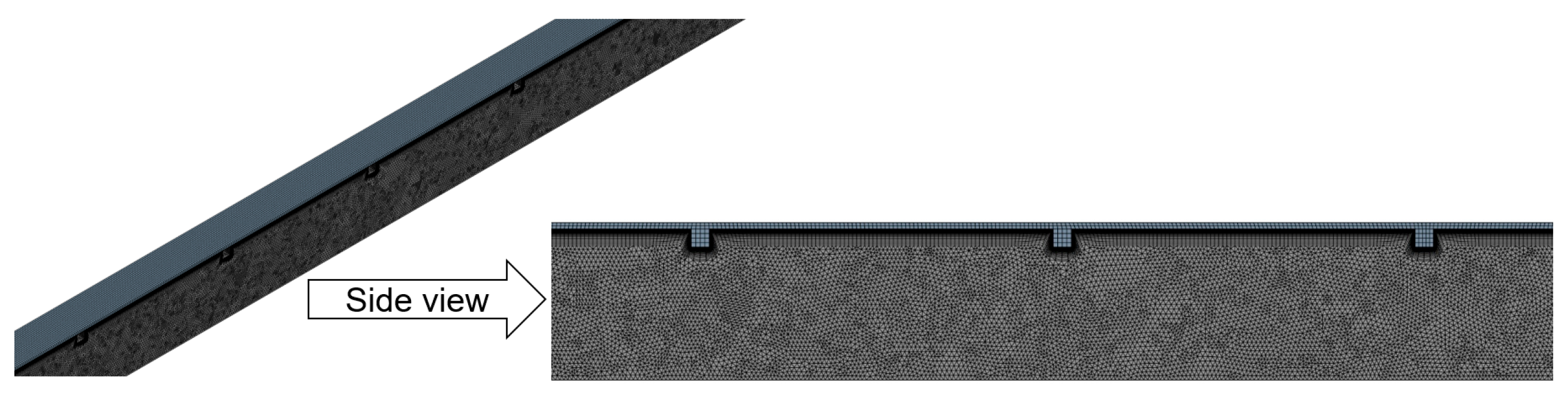
2.3. Grid Independence Test

A 3D model for the simulation was prepared using ANSYS Design Modeler, and a non-uniform mesh was generated with ANSYS ICEM CFD. The number of cells was increased from 1,381,060 to 8,486,004 to confirm grid independence. To ensure grid independence, the Nusselt number and friction factor were evaluated, similar to the other relative studies [22,30,39]. Table 3 presents the variations in Nusselt number at the base surface ( N u b ); Nusselt number at the side surface ( N u s ); and average friction factor ( f a v g ) with changes in cell number for a relative height ( e / D h ) of 0.12, a relative pitch of 10 ( P / e ), and a R e of 9000. The results fluctuated with increasing cell number. However, the changes in results indicated that further increases in cell number beyond 5,250,974 led to changes in N u b , N u s , and f a v g of less than 1%. Therefore, a cell number of 5,250,974 was selected for further analysis. The computational domain with the chosen mesh density is shown in Figure 3.

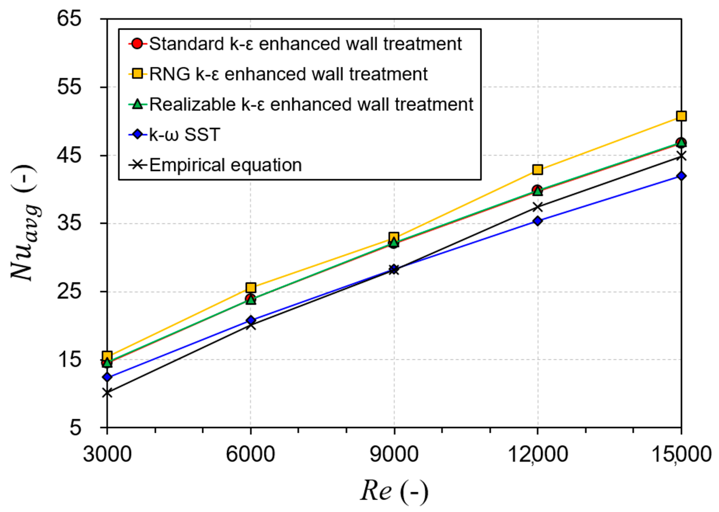
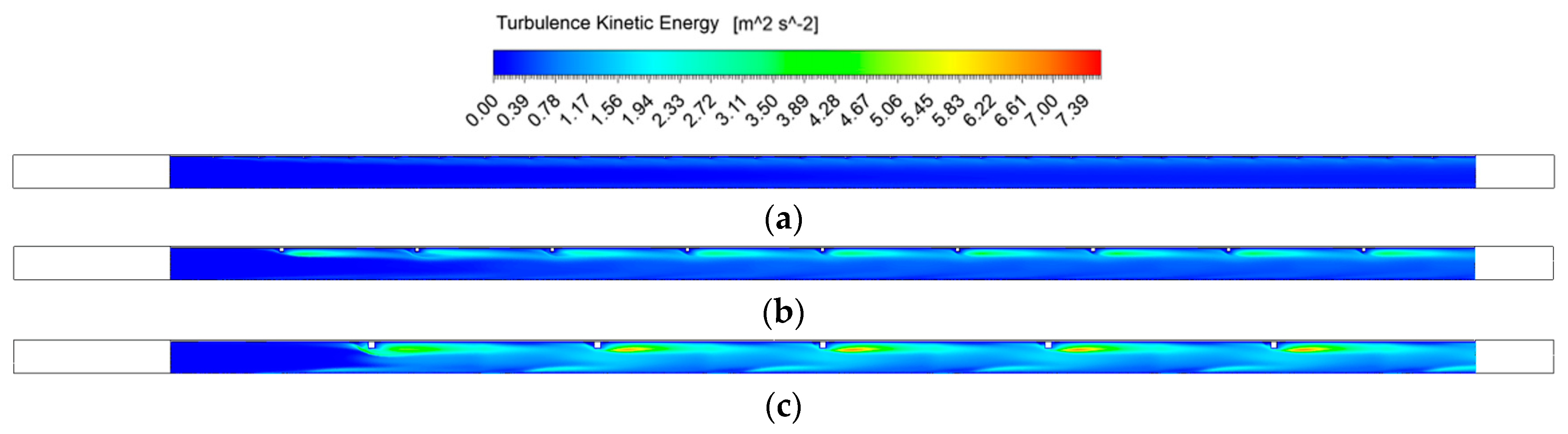
2.4. Turbulence Model Selection

Many studies on the CFD analysis of an SAH have selected an appropriate turbulence model and validated the developed model by comparing simulation results with empirical equation values [23,30,40]. Thus, this study also compared the simulated N u and f values for a smooth-finned channel, obtained using various turbulence models, with empirical values to select the appropriate model. To obtain the empirical N u values, Gnielinski and Dittus–Boelter correlations—widely used for SAH simulation—were employed, as shown in Equations (1) and (2) [20,35,40,41].
N u r e f = f g / 8 R e 1000 P r 1 + 12.7 f g / 8 1 / 2 P r 2 / 3 1   f o r   3000 < R e < 10,000
N u r e f = 0.023 R e 0.8 P r 0.4   f o r   10,000 < R e
Here, f g represents the friction factor used in the Gnielinski correlation. It was calculated using Equation (3).
f g = 0.79 ln R e 1.64 2
Figure 4 compares the simulated average Nusselt number ( N u a v g ) obtained using various turbulence models with empirical values. The figure confirms that the k ω SST model yields the lowest mean absolute percentage error (MAPE) of 7.41% for N u a v g between the simulated and empirical values. This result is consistent with the results reported in similar previous studies [26,42,43,44,45,46]. Therefore, the k ω SST model was selected for further analysis.

2.5. Performance Indices

This study sought to assess the heat transfer enhancement and associated pressure drop resulting from obstacles sequentially arranged on the fin surface. Heat transfer takes place on both the fin’s upper and vertical surfaces. Accordingly, N u b and N u s were evaluated as follows:
N u b = h b D h k a i r
N u s = h s D h k a i r
The convective heat transfer corresponding to each fin surface was computed based on Equations (6) and (7).
h b = Q ˙ b A b T b T a i r
h s = Q ˙ s A s T s T a i r
The average N u on the fin was obtained from Equation (8).
N u a v g = h a v g D h k a i r
The total fin-to-air heat transfer can be expressed as Equation (9).
Q ˙ t = h a v g A t T f i n T a i r = Q ˙ b + Q ˙ s
Therefore, the average convective heat transfer coefficient can be obtained from Equation (10).
h a v g = h b A b T b T a i r + h s A s T s T a i r A t T f i n T a i r
The average friction factor due to the obstacle was calculated using Equation (11) [47,48,49].
f a v g = P / L a c D h 2 ρ a i r V a i r 2
The rectangular obstacle installed on the fin surface not only improves heat transfer performance but also increases the pressure drop. Therefore, this study evaluates the thermo-hydraulic performance (THP) as a combined measure of both enhanced heat transfer and its resulting pressure penalty. The THP is calculated using Equation (12) [20,50,51,52].
T H P = N u a v g / N u r e f f a v g / f r e f 1 / 3
where f r e f represents the friction factor for a smooth-finned channel. A higher THP indicates more effective heat transfer enhancement under similar pressure drops.

3. Results and Discussion

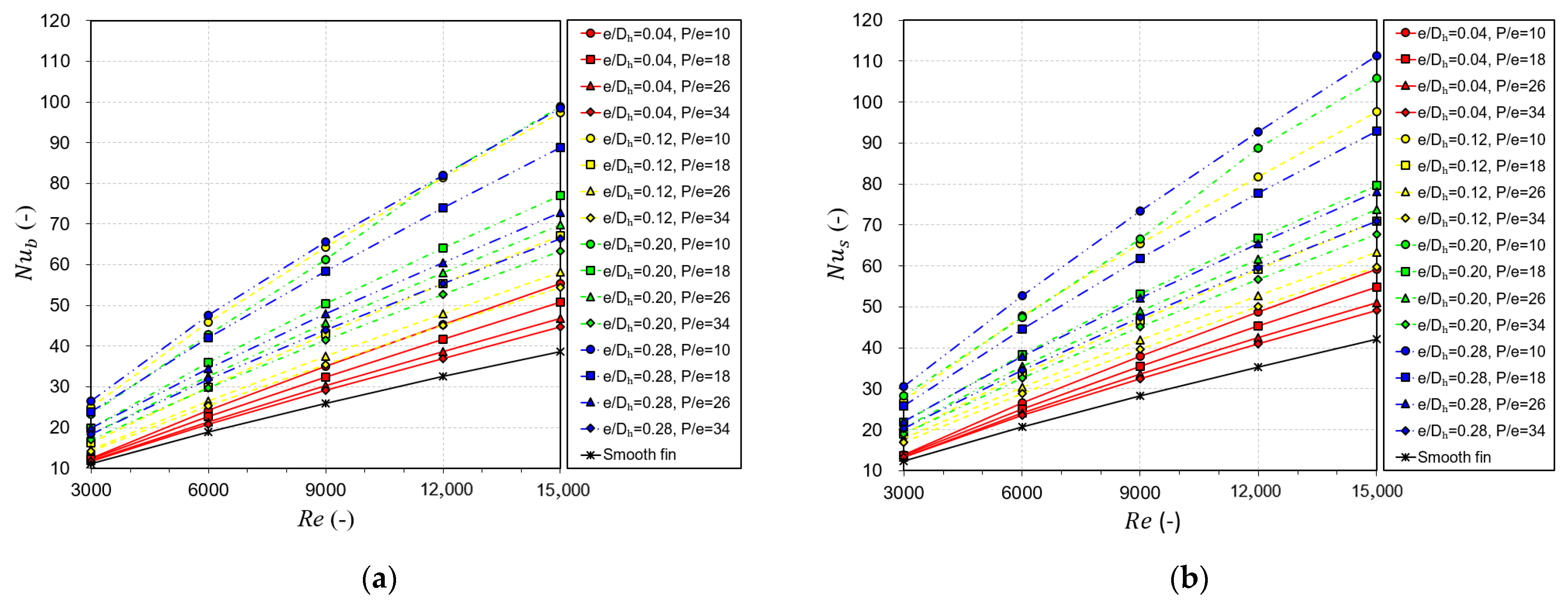
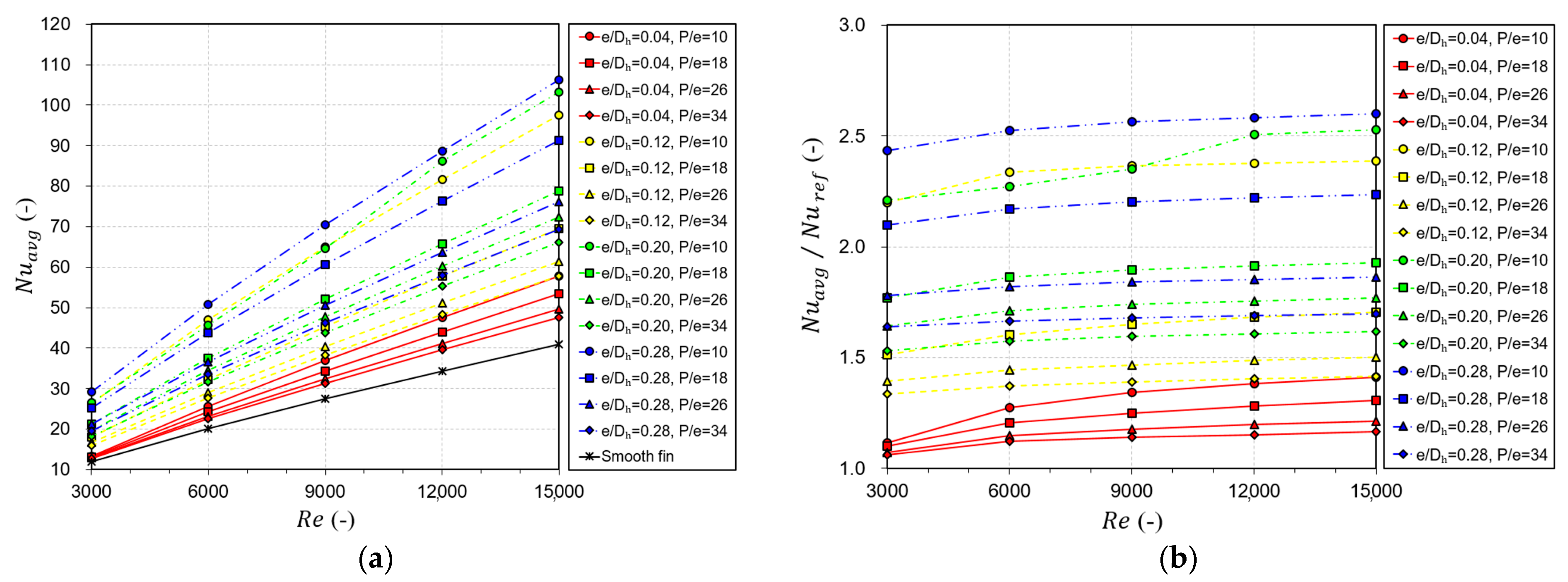
3.1. Heat Transfer Performance

This subsection demonstrates heat transfer enhancement through the installation of obstacles with various heights and pitches. Figure 5 presents N u on the base and side surfaces. It is apparent that incorporating obstacles enhances heat transfer performance in a finned air channel. The values of N u b and N u s ranged from 11.14 to 98.96 and from 12.40 to 111.24, respectively. Both values increased with increasing R e , as a higher R e promotes turbulence generation near the hot surface, thereby enhancing convective heat transfer, as reported in several related studies [16,17,18,19,35,36].
It was also observed that a larger relative height ( e / D h ) and a smaller relative pitch ( P / e ) resulted in greater heat transfer enhancement. This is because a larger relative height increases the turbulence kinetic energy, as shown in Figure 6, while a smaller relative pitch increases the total number of installed obstacles.
Figure 7 presents N u a v g and its enhancement. The value of N u a v g ranged from 11.97 to 106.28, varying with the relative height and pitch of the obstacle and R e . As shown previously, N u a v g tended to increase with increasing relative height, decreasing relative pitch, and increasing R e .
Due to the presence of obstacles, N u a v g was enhanced by a factor of 1.061 to 2.602 compared to the smooth-fin case. The minimum enhancement in N u a v g was observed at a relative height of 0.04, a relative pitch of 34, and a R e of 3000, whereas the maximum enhancement occurred at 0.28, 10, and 15,000, respectively.

3.2. Fluid Friction

This section presents the friction factor, with the obstacle increasing the pressure drop in addition to enhancing heat transfer performance. Figure 8 shows f a v g and its increase. In all cases, the presence of obstacles led to an increase in f a v g . The value of f a v g ranged from 0.0117 to 0.2578, varying with the relative heights, relative pitches, and R e . It tended to rise with increasing relative height and decrements in relative pitch. The reason is that increasing the relative height and the number of obstacles resulting from a smaller relative pitch causes greater flow disruption, leading to an increased pressure drop. R e had a lesser effect on f a v g compared to the relative height and pitch. This is because the increase in pressure drop, which is proportional to f a v g , is similar to the velocity-squared increase, which is inversely proportional to f a v g , as R e increases.
The increase in f a v g varied from 1.20 to 36.95 times. The minimum increase occurred at a relative height of 0.04, a relative pitch of 34, and a R e of 3000, whereas the maximum increase was observed at 0.28, 10, and 15,000, respectively.

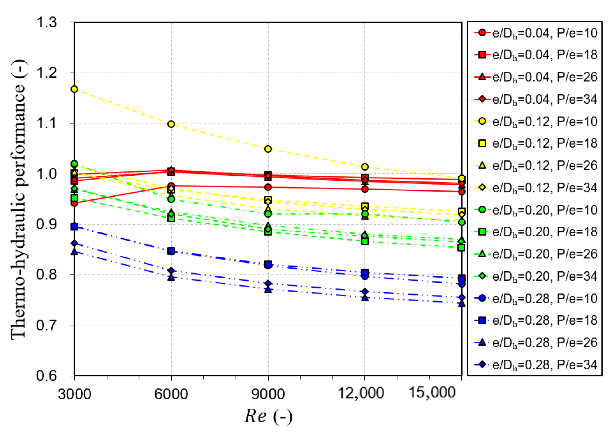
3.3. Thermo-Hydraulic Performance

The results described in the previous subsections clearly show that a higher relative height and a smaller relative pitch not only enhance heat transfer performance, but also increase the pressure drop. Accordingly, the THP values, which reflect both heat transfer enhancement and the associated pressure drop, are presented in Figure 9.
The value of THP ranged from 0.744 to 1.167. An increase in R e tended to decrease the THP value. This implies that the pressure penalty due to higher R e outweighed the corresponding enhancement in heat transfer. The highest THP values were observed when the relative height and relative pitch were 0.12 and 10, respectively, regardless of R e . Therefore, the combination of a relative height of 0.12 and a relative pitch of 10 was considered the most suitable geometric condition for the sequentially placed rectangular obstacles among the investigated cases. In contrast, the THP corresponding to a relative height of 0.28 exhibited the lowest values across all R e and relative pitch conditions, despite providing the highest heat transfer augmentation. This is because the increase in pressure drop outweighed the improvement in heat transfer. Accordingly, a relative height of 0.28 was identified as an unsuitable design parameter for obstacles in a finned SAH.

3.4. Correlation Derivation

N u and f are essential for modeling the thermal behavior of an SAH and for predicting its thermal performance and fan power consumption. Therefore, this subsection derives the correlations for N u and f as functions of relative height, relative pitch, and R e . The correlations were developed based on log–log plots, and the results are presented in Equations (13)–(15). A detailed description of the methodology can be found in related studies [1,35,51,53].
N u b = 0.10701 R e 0.8483 e / D h 0.1503 P / e 0.5465 e x p 0.0274 l n e / D h 2 e x p 0.0395 l n P / e 2
N u s = 0.20289 R e 0.8106 e / D h 0.1384 P / e 0.7287 e x p 0.0283 l n e / D h 2 e x p 0.0738 l n P / e 2
f a v g = 25.455 R e 0.0228 e / D h 2.2881 P / e 1.2153 e x p 0.2659 l n e / D h 2 e x p 0.0697 l n P / e 2
Figure 10 compares the simulated values of N u b , N u s , and f a v g from the CFD analysis with the values predicted by the derived correlations under identical conditions. The results confirm that the predicted values are in good agreement with the simulated values, with MAPEs of 5.08% for N u b , 4.55% for N u s , and 9.66% for f a v g .

4. Conclusions

In this work, the effects of the geometric conditions of sequentially placed obstacles in a finned channel, incorporated into an SAH, on thermal and flow characteristics were investigated through CFD analysis. The key findings are as follows:
(1)
An increase in N u a v g was observed with higher relative obstacle height, lower relative obstacle pitch, and higher R e . The sequentially placed obstacles enhanced N u a v g by 2.602 times for the case where a relative height of 0.28, a relative pitch of 10, and a R e of 15,000 were used.
(2)
Elevating the relative height and reducing the relative pitch led to an increment in f a v g , while R e had a comparatively smaller effect. The value of f a v g increased by 36.95 times compared to the smooth-fin case at a relative height of 0.28, a relative pitch of 10, and a R e of 3000.
(3)
The THP values varied from 0.744 to 1.167. The highest THP was achieved at a relative height of 0.12 and a relative pitch of 10, regardless of R e . Therefore, these conditions were deemed the most suitable for the obstacles when considering both thermal performance and flow resistance.
(4)
Correlations for N u s , N u b , and f a v g were derived as functions of relative height, relative pitch, and R e . The values of N u s , N u b , and f a v g were accurately predicted by the correlations with MAPEs of 5.08%, 4.55%, and 9.66%, respectively.
This study confirms that sequentially placed obstacles effectively enhance heat transfer in the finned channel of an SAH. However, the scope of this study was limited to the analysis of heat transfer and pressure penalty within the fluid domain. The temperature rise and thermal efficiency are the most important parameters for an SAH from a practical point of view. Therefore, future research will involve both experimental studies and numerical analyses of the proposed SAH to evaluate its performance, including air temperature rise and thermal efficiency. In addition, an economic analysis should be conducted to confirm the feasibility of the proposed design because the initial cost and fan power increase due to the use of the obstacles. The findings and derived correlations from this research are anticipated to offer useful information for further investigation.

Author Contributions

Conceptualization, B.-H.A. and S.-B.K.; methodology, B.-H.A.; software, B.-H.A., K.-A.M. and H.-U.C.; validation, B.-H.A.; investigation, B.-H.A. and H.-U.C.; data curation, K.-A.M. and S.-B.K.; writing—original draft preparation, B.-H.A. and H.-U.C.; writing—review and editing, H.-U.C.; visualization, B.-H.A. and K.-A.M. All authors have read and agreed to the published version of the manuscript.

Funding

This research received no external funding.

Data Availability Statement

Data available on request.

Acknowledgments

This research was supported by the Regional Innovation System & Education (RISE) program, funded by the Ministry of Education and the Jeollanam-do Provincial Government.

Conflicts of Interest

The authors declare no conflicts of interest.

Nomenclature

A b Surface area of the base fin (m2)
A s Surface area of the side fin (m2)
A t Total surface area of the fin (m2)
D h Hydraulic diameter (m)
f a v g Average friction factor (-)
f g Friction factor for Gnielinski correlation (-)
f r e f Smooth-finned air channel friction factor (-)
h a v g Average convective heat transfer coefficient between the fin and the flowing air (W/m2·K)
h b Convective heat transfer coefficient at the base surface of the fin (W/m2·K)
h s Convective heat transfer coefficient at the side surface of the fin (W/m2·K)
k a i r Thermal conductivity of the air (W/m·K)
L a c Length of the finned air channel (m)
N u a v g Average Nusselt number at the fin–air interface (-)
N u b Nusselt number on the fin base surface (-)
N u r e f Nusselt number for the smooth-finned air channel (-)
N u s Nusselt number on the fin side surface (-)
P Pressure drop (Pa)
P r Prandtl number (-)
Q ˙ b Heat transfer rate at the base surface of the fin (W)
Q ˙ s Heat transfer rate at the side surface of the fin (W)
Q ˙ t Total fin-to-air heat transfer rate (W)
R e Reynolds number (-)
T a i r Temperature of the flowing air (°C)
T b Temperature at the base surface of the fin (°C)
T f i n Average temperature of the base and side of the fin (°C)
T s Temperature on the side surface of the fin (°C)
V a i r Velocity of the air (m/s)
Greek symbol
ρ a i r Air density (kg/m3)

References

  1. Chamoli, S.; Lu, R.; Xu, D.; Yu, P. Thermal performance improvement of a solar air heater fitted with winglet vortex generators. Sol. Energy 2018, 159, 966–983. [Google Scholar] [CrossRef]
  2. Singh, V.P.; Jain, S.; Karn, A.; Kumar, A.; Dwivedi, G.; Meena, C.S.; Dutt, N.; Ghosh, A. Recent Developments and Advancements in Solar Air Heaters: A Detailed Review. Sustainability 2022, 14, 12149. [Google Scholar] [CrossRef]
  3. Markam, B.; Maiti, S. Artificial enhancer for small-scale solar air heater—A comprehensive review. Clean. Energy Syst. 2023, 4, 100046. [Google Scholar] [CrossRef]
  4. Fakoor Pakdaman, M.; Lashkari, A.; Basirat Tabrizi, H.; Hosseini, R. Performance evaluation of a natural-convection solar air-heater with a rectangular-finned absorber plate. Energy Convers. Manag. 2011, 52, 1215–1225. [Google Scholar] [CrossRef]
  5. Fudholi, A.; Sopian, K.; Ruslan, M.H.; Othman, M.Y. Performance and cost benefits analysis of double-pass solar collector with and without fins. Energy Convers. Manag. 2013, 76, 8–19. [Google Scholar] [CrossRef]
  6. Priyam, A.; Chand, P. Thermal and thermohydraulic performance of wavy finned absorber solar air heater. Sol. Energy 2016, 130, 250–259. [Google Scholar] [CrossRef]
  7. Kabeel, A.E.; Hamed, M.H.; Omara, Z.M.; Kandeal, A.W. Influence of fin height on the performance of a glazed and bladed entrance single-pass solar air heater. Sol. Energy 2018, 162, 410–419. [Google Scholar] [CrossRef]
  8. Chand, S.; Chand, P.; Kumar Ghritlahre, H. Thermal performance enhancement of solar air heater using louvered fins collector. Sol. Energy 2022, 239, 10–24. [Google Scholar] [CrossRef]
  9. Karwa, R. Thermo-hydraulic performance of solar air heater with finned absorber plate forming multiple rectangular air flow passages in parallel under laminar flow conditions. Appl. Therm. Eng. 2023, 221, 119673. [Google Scholar] [CrossRef]
  10. Vengadesan, E.; Arunkumar, T.; Krishnamoorthi, T.; Senthil, S. Thermal performance improvement in solar air heating: An absorber with continuous and discrete tubular and v-corrugated fins. Therm. Sci. Eng. Prog. 2024, 48, 102416. [Google Scholar] [CrossRef]
  11. Elakrout, O.; Ghriss, O.; Bouabidi, A.; Garcia Castellanos, H.; Mohtaram, S.; Keçebaş, A.; Aryanfar, Y. Investigative analysis of the influence of diverse fin configurations on the performance of a dual pass solar air collector. Therm. Sci. Eng. Prog. 2024, 50, 102545. [Google Scholar] [CrossRef]
  12. Yang, M.; Yang, X.; Li, X.; Wang, Z.; Wang, P. Design and optimization of a solar air heater with offset strip fin absorber plate. Appl. Energy 2014, 113, 1349–1362. [Google Scholar] [CrossRef]
  13. Saravanan, A.; Parida, S.; Murugan, M.; Reddy, M.S.; Elumalai, P.V.; Kumar Dash, S. Thermal performance prediction of a solar air heater with a C-shape finned absorber plate using RF, LR and KNN models of Machine learning. Therm. Sci. Eng. Prog. 2023, 38, 101630. [Google Scholar] [CrossRef]
  14. Albdoor, A.K.; Obaid, Z.A.H.; Kamel, M.S.; Azzawi, I.D.J. Energy, exergy, economic and environmental analysis of a solar air heater integrated with double triangular fins: Experimental investigation. Int. J. Thermofluids 2024, 24, 100979. [Google Scholar] [CrossRef]
  15. Singh Bisht, V.; Kumar Patil, A.; Gupta, A. Review and performance evaluation of roughened solar air heaters. Renew. Sustain. Energy Rev. 2018, 81, 954–977. [Google Scholar] [CrossRef]
  16. Yadav, A.S.; Bhagoria, J.L. A CFD (computational fluid dynamics) based heat transfer and fluid flow analysis of a solar air heater provided with circular transverse wire rib roughness on the absorber plate. Energy 2013, 55, 1127–1142. [Google Scholar] [CrossRef]
  17. Yadav, A.S.; Bhagoria, J.L. A numerical investigation of square sectioned transverse rib roughened solar air heater. Int. J. Therm. Sci. 2014, 79, 111–131. [Google Scholar] [CrossRef]
  18. Yadav, A.S.; Bhagoria, J.L. A CFD based thermo-hydraulic performance analysis of an artificially roughened solar air heater having equilateral triangular sectioned rib roughness on the absorber plate. Int. J. Heat Mass Transf. 2014, 70, 1016–1039. [Google Scholar] [CrossRef]
  19. Gawande, V.B.; Dhoble, A.S.; Zodpe, D.B.; Chamoli, S. Experimental and CFD investigation of convection heat transfer in solar air heater with reverse L-shaped ribs. Sol. Energy 2016, 131, 275–295. [Google Scholar] [CrossRef]
  20. Singh, I.; Singh, S. CFD analysis of solar air heater duct having square wave profiled transverse ribs as roughness elements. Sol. Energy 2018, 162, 442–453. [Google Scholar] [CrossRef]
  21. Singh, I.; Vardhan, S.; Singh, S.; Singh, A. Experimental and CFD analysis of solar air heater duct roughened with multiple broken transverse ribs: A comparative study. Sol. Energy 2019, 188, 519–532. [Google Scholar] [CrossRef]
  22. Kumar, R.; Goel, V. Unconventional solar air heater with triangular flow-passage: A CFD based comparative performance assessment of different cross-sectional rib-roughnesses. Renew. Energy 2021, 172, 1267–1278. [Google Scholar] [CrossRef]
  23. Boussouar, G.; Rostane, B.; Aliane, K.; Ravi, D.; Gęca, M.J.; Gola, A. Study of the Thermal Performance of Solar Air Collectors with and without Perforated Baffles. Energies 2024, 17, 3812. [Google Scholar] [CrossRef]
  24. Kumar, B.V.; Kanna, P.R.; Manikandan, G.; Taler, D.; Taler, J.; Sobota, T.; Nowak-Ocłoń, M. Investigation of Thermo-Hydraulic Performances of Artificial Ribs Mounted in a Rectangular Duct. Energies 2023, 16, 4404. [Google Scholar] [CrossRef]
  25. Khanlari, A.; Güler, H.Ö.; Tuncer, A.D.; Şirin, C.; Bilge, Y.C.; Yılmaz, Y.; Güngör, A. Experimental and numerical study of the effect of integrating plus-shaped perforated baffles to solar air collector in drying application. Renew. Energy 2020, 145, 1677–1692. [Google Scholar] [CrossRef]
  26. Alam, M.W.; Souayeh, B. Parametric CFD Thermal Performance Analysis of Full, Medium, Half and Short Length Dimple Solar Air Tube. Sustainability 2021, 13, 6462. [Google Scholar] [CrossRef]
  27. Choi, H.; Choi, K. Parametric study of a novel air-based photovoltaic-thermal collector with a transverse triangular-shaped block. Renew. Energy 2022, 201, 96–110. [Google Scholar] [CrossRef]
  28. Haldar, A.; Varshney, L.; Verma, P. Effect of roughness parameters on performance of solar air heater having artificial wavy roughness using CFD. Renew. Energy 2022, 184, 266–279. [Google Scholar] [CrossRef]
  29. Hu, J.; Zhang, Y.; Xie, S.; Xiao, Y. Thermo-hydraulic performance of solar air heater with built-in one-eighth sphere vortex generators. Appl. Therm. Eng. 2024, 245, 122837. [Google Scholar] [CrossRef]
  30. Singh, S.; Suman, S.; Mitra, S.; Kumar, M. Thermo-hydraulic performance enhancement of a solar air heater using rotating cylindrical turbulators. Appl. Therm. Eng. 2024, 236, 121748. [Google Scholar] [CrossRef]
  31. Mahanand, Y.; Senapati, J.R. Implementation of hybrid rib-turbulators on the thermal performance of solar air heater duct: A collective review. Sustain. Energy Technol. Assess. 2022, 52, 102345. [Google Scholar] [CrossRef]
  32. Hassan, A.; Nikbakht, A.M.; Fawzia, S.; Yarlagadda, P.; Karim, A. A Comprehensive Review of the Thermohydraulic Improvement Potentials in Solar Air Heaters through an Energy and Exergy Analysis. Energies 2024, 17, 1526. [Google Scholar] [CrossRef]
  33. Nidhul, K.; Yadav, A.K.; Anish, S.; Kumar, S. Critical review of ribbed solar air heater and performance evaluation of various V-rib configuration. Renew. Sustain. Energy Rev. 2021, 142, 110871. [Google Scholar] [CrossRef]
  34. Ghritlahre, H.K.; Verma, M.; Parihar, J.S.; Mondloe, D.S.; Agrawal, S. A detailed review of various types of solar air heaters performance. Sol. Energy 2022, 237, 173–195. [Google Scholar] [CrossRef]
  35. Choi, H.-U.; Moon, K.-A.; Kim, S.-B.; Choi, K.-H. CFD Analysis of the Heat Transfer and Fluid Flow Characteristics Using the Rectangular Rib Attached to the Fin Surface in a Solar Air Heater. Sustainability 2023, 15, 5382. [Google Scholar] [CrossRef]
  36. An, B.-H.; Choi, K.-H.; Choi, H.-U. Heat Transfer Augmentation and Friction Factor Due to the Arrangement of Rectangular Turbulators in a Finned Air Channel of a Solar Air Heater. Energies 2023, 16, 6891. [Google Scholar] [CrossRef]
  37. Diana, L.; Safitra, A.G.; Muhammad, G. Numerical Investigation of Airflow in a Trapezoidal Solar Air Heater Channel. In Proceedings of the 2019 International Electronics Symposium (IES), Surabaya, Indonesia, 27–28 September 2019; pp. 248–253. [Google Scholar]
  38. Al-Abbasi, O.; Sarac, B.; Ayhan, T. Experimental Investigation and CFD Modeling to Assess the Performance of Solar Air Humidifier. Int. J. Heat Technol. 2019, 37, 357–364. [Google Scholar] [CrossRef]
  39. Qader, B.S.; Supeni, E.E.; Ariffin, M.K.A.; Talib, A.R.A. RSM approach for modeling and optimization of designing parameters for inclined fins of solar air heater. Renew. Energy 2019, 136, 48–68. [Google Scholar] [CrossRef]
  40. Singh, S.; Singh, B.; Hans, V.S.; Gill, R.S. CFD (computational fluid dynamics) investigation on Nusselt number and friction factor of solar air heater duct roughened with non-uniform cross-section transverse rib. Energy 2015, 84, 509–517. [Google Scholar] [CrossRef]
  41. Singh, A.; Singh, S. CFD investigation on roughness pitch variation in non-uniform cross-section transverse rib roughness on Nusselt number and friction factor characteristics of solar air heater duct. Energy 2017, 128, 109–127. [Google Scholar] [CrossRef]
  42. Chaube, A.; Sahoo, P.K.; Solanki, S.C. Analysis of heat transfer augmentation and flow characteristics due to rib roughness over absorber plate of a solar air heater. Renew. Energy 2006, 31, 317–331. [Google Scholar] [CrossRef]
  43. Alam, T.; Kim, M.-H. Heat transfer enhancement in solar air heater duct with conical protrusion roughness ribs. Appl. Therm. Eng. 2017, 126, 458–469. [Google Scholar] [CrossRef]
  44. Kumar, S.; Verma, S.K. Heat transfer and fluid flow analysis of sinusoidal protrusion rib in solar air heater. Int. J. Therm. Sci. 2022, 172, 107323. [Google Scholar] [CrossRef]
  45. Wongcharee, K.; Changcharoen, W.; Eiamsa-ard, S. Numerical Investigation of Flow Friction and Heat Transfer in a Channel with Various Shaped Ribs Mounted on Two Opposite Ribbed Walls. Int. J. Chem. React. Eng. 2011, 9, A26. [Google Scholar] [CrossRef]
  46. Boulemtafes-Boukadoum, A.; Benzaoui, A. CFD based Analysis of Heat Transfer Enhancement in Solar Air Heater Provided with Transverse Rectangular Ribs. Energy Procedia 2014, 50, 761–772. [Google Scholar] [CrossRef]
  47. Kumar, R.; Goel, V.; Kumar, A. Investigation of heat transfer augmentation and friction factor in triangular duct solar air heater due to forward facing chamfered rectangular ribs: A CFD based analysis. Renew. Energy 2018, 115, 824–835. [Google Scholar] [CrossRef]
  48. Kim, S.-B.; Choi, H.-U. Numerical analysis of photovoltaic–thermal air collector with fins and rectangular turbulators. Therm. Sci. Eng. Prog. 2025, 59, 103393. [Google Scholar] [CrossRef]
  49. Choi, H.-U. Dynamic analysis of air-based photovoltaic–thermal system with fins and rectangular obstacles. Appl. Therm. Eng. 2025, 272, 126412. [Google Scholar] [CrossRef]
  50. Webb, R.L.; Eckert, E.R.G. Application of rough surfaces to heat exchanger design. Int. J. Heat Mass Transf. 1972, 15, 1647–1658. [Google Scholar] [CrossRef]
  51. Kumar, R.; Kumar, A.; Goel, V. Performance improvement and development of correlation for friction factor and heat transfer using computational fluid dynamics for ribbed triangular duct solar air heater. Renew. Energy 2019, 131, 788–799. [Google Scholar] [CrossRef]
  52. Gupta, A.D.; Varshney, L. Performance prediction for solar air heater having rectangular sectioned tapered rib roughness using CFD. Therm. Sci. Eng. Prog. 2017, 4, 122–132. [Google Scholar] [CrossRef]
  53. Choi, H.-U.; Choi, K.-H. CFD Analysis on the Heat Transfer and Fluid Flow of Solar Air Heater having Transverse Triangular Block at the Bottom of Air Duct. Energies 2020, 13, 1099. [Google Scholar] [CrossRef]
Figure 1. A schematic of an SAH with sequentially placed obstacles in a finned air channel.
Energies 18 03811 g001
Figure 2. The computational domain of the SAH: (a) isometric view; (b) side view.
Energies 18 03811 g002
Figure 3. Meshed computational domain with selected cell number.
Energies 18 03811 g003
Figure 4. Comparison of simulated values obtained using various turbulence models with empirical values.
Energies 18 03811 g004
Figure 5. N u under varying relative heights and pitches: (a) base; (b) side.
Energies 18 03811 g005
Figure 6. Contours of turbulence kinetic energy for different relative heights at fixed relative pitch of 18 and R e of 9000: (a) e / D h = 0.04; (b) e / D h = 0.12; (c) e / D h = 0.20.
Energies 18 03811 g006
Figure 7. N u a v g under varying relative heights and pitches: (a) N u a v g ; (b) enhancement in N u a v g .
Energies 18 03811 g007
Figure 8. f a v g under varying relative heights and pitches: (a) f a v g ; (b) increase in f a v g .
Energies 18 03811 g008
Figure 9. THP values under varying relative heights and pitches.
Energies 18 03811 g009
Figure 10. Comparison of simulated and predicted values of N u b , N u b , and f a v g .
Energies 18 03811 g010
Table 1. The geometric conditions of a computational domain.
ParameterNomenclatureValue
Length of entrance section (mm) L e n t 120
Length of test section (mm) L t e s t 1000
Length of exit section (mm) L e x i t 60
Height of fin (mm) H f i n 25
Width of fin (mm) W f i n 12.5
Height of finned channel (mm) H a c 24
Width of finned channel (mm) W a c 12
Thickness of side fin (mm) t f i n , s 0.5
Thickness of base fin (mm) t f i n , b 1
Hydraulic diameter of finned channel (mm) D h 24
Relative height (-) e / D h 0.04, 0.12, 0.20, 0.28
Relative pitch (-) p / e 10, 18, 26, 34
Table 2. Boundary conditions.
BoundaryConditionValue
Top of base surfaceHeat flux (W/m2)800
Mid-plain of finned channelSymmetry-
Fin’s side surfaceSymmetry-
Other wallsAdiabatic-
InletReynolds number (-)
velocity (m/s)
3000, 6000, 9000, 12,000, 15,000
1.683, 3.366, 5.048, 6.731, 8.414
OutletPressure (kPa)101.325
Table 3. Changes in N u s , N u b , and f a v g with various cell numbers.
Cell Number N u s (-) Change   in   N u s (%) N u b (-) Change   in   N u b (%) f a v g (-) Change   in   f a v g (%)
1,381,06059.62-63.41-0.07045-
2,779,15059.250.6258.248.160.0842519.59
5,250,97459.981.2358.991.290.084300.06
6,622,86159.890.1459.290.510.083960.40
8,486,00460.350.7759.650.610.084080.14
Disclaimer/Publisher’s Note: The statements, opinions and data contained in all publications are solely those of the individual author(s) and contributor(s) and not of MDPI and/or the editor(s). MDPI and/or the editor(s) disclaim responsibility for any injury to people or property resulting from any ideas, methods, instructions or products referred to in the content.

