Abstract
There has been a great need for replacing combustion-powered vehicles with electric vehicles (EV), and fully electric cars are meant to replace combustion engine cars. This has led to considerable research into improving the performance of EVs, especially via electric motor voltage control. A wide range of optimization algorithms have been used as traditional approaches, but the dynamic parameters of electric motors, impacted by temperature and different driving cycles, continue to be a problem. This study introduces an improved version of the Parrot Optimizer (IPO) aimed at enhancing voltage regulation in EVs. The algorithm can intelligently adjust certain motor parameters for adaptive management to maintain performance based on different situations. To ensure a stable and sustainable power supply for the powertrain of the EV, a photovoltaic (PV) system is used with energy storage batteries. Such an arrangement seeks to deliver permanent electric energy, a solution to traditional grid electricity reliance. This demonstrates the effectiveness of IPO, with the resultant motor performance remaining optimal despite parameter changes. It is also illustrated that energy production, by integrating PV systems, prevents excessive voltage line drops and thus voltage imbalances. The proposed intelligent controller is verified based on multiple simulations, demonstrating and ensuring significant improvements in EV efficiency and reliability.
1. Introduction
Recently, electric vehicles (EVs) have attracted much attention; as a result, governments have been encouraging individuals to buy those products. So, it is important to have complete information about these cars [1]. An EV is a vehicle that possesses more than one motor of electricity and supplies the energy from the rechargeable batteries. Batteries that have been often installed under the vehicle’s floor [2]. EVs are diverse from plug-in hybrids to hybrid cars since they lack a diesel or gasoline internal engine of combustion [3].
To recharge the EV’s battery, it is needed to plug it into a household socket or a public charging network [4]. Electric cars are becoming more prevalent since they are pollution-free. These cars do not produce carbon dioxide or particulate matter which contribute to global warming and damage to quality of air, particularly in urban places. A fundamental issue of EV deployment is the dynamics of its electric motor parameters according to the environment and driving cycles. The system is variable and dynamic and requires an advanced control mechanisms to ensure the performance of the motor and the stability of the vehicle [5]. The emergence of the distribution system operator (DSO) paradigm, where the distribution system starts to be operated analogously to a transmission system in a competitive electricity market, reinforces the need for an efficient and reliable voltage control scheme. Within such a framework, the DSO functions encompass not only the provision of electrical energy to the consumer but of the upkeep and design of a reliable and efficient distribution grid [6]. This has introduced new complexities and opportunities for optimizing voltage control in EVs with the advent of smart grids and the integration of renewable energy sources. The work from [7] emphasized the need for EV charging infrastructure optimization, which is also the core of this study, focusing on EV battery charging time minimization through using enhanced Parrot Optimizer along with photovoltaic (PV) systems. Advanced control strategies were presented in [8] for power system optimization, which is another approach to deduce the objective function in power systems. This is ultimately relevant since our focus lies in optimizing the efficiency of electric vehicle charging through an enhanced version of the Parrot Optimizer. One example, provided by [9], highlights the necessity to monitor and improve the performance of PV systems, a performance that can be directly associated with the proposed system in this study regarding the enhancement of EV battery charging efficiency using PV systems. Novelties in optimization algorithms have opened possibilities for tackling these challenges. For example, Morais suggested an energy management system for EV charging in parking lots under a dual objective of maximizing a fairness index and minimizing operating costs considering various types of contracts of users and multi-outlet charging stations [10]. Unlike other approaches that previously concentrated on minimizing costs and required detailed information on travel, this approach balanced the fairness of attaining a desired state-of-charge level by departure so that the fairness index was shown to work better, achieving 0.289–0.748, compared to first-come-first-served strategies. Such a model was presented as an optimization problem, which is to be solved with mixed-integer linear programming and further refined through case studies of charging 100 EVs in residential contexts. This study had other limitations, among which are simplistically modeled vehicle usage patterns and charging infrastructures that may not completely reflect real-world variability. Furthermore, it did not examine the scalability of the same to larger or more complex networks. Some implementation checks such as communication barriers between the vehicles and the management system were not explored significantly. These limitations warrant further investigation in the areas of robustness, prototype adaptability, and integration with other smart grid systems.
An improved control structure for off-board EV chargers was introduced by Vinoth Kumar and Dhayalini by optimally tuning the PI controller using a novel Assailant-Inspired Chimp Optimization Algorithm (AIChOa) to overcome the voltage synchronization, reactive power control, and harmonic reduction limitations [11]. This allowed the charger to operate efficiently in grid-to-vehicle and vehicle-to-grid modes, providing grid functions such as voltage regulation and THD reduction. The method has shown its edge within some recent optimization techniques, achieving 24.77% THD reduction with higher fitness values and faster convergence as well as better dynamic and steady-state response. The major drawback, however, is that this study was validated mainly through simulations and thus lacks practical implications. Small sample size and limited scope of comparative analysis may have limited the generalizability of the results to varied charging scenarios and grid conditions. El Mezdi et al. [12] conducted a study in which an optimizer addressed diverse modes of operating, like constant voltage (CV) and constant current (CC), for enhancing the stability of the network, optimizing the distribution of energy between the EV and the various sources, and improving quality of energy. The suggested fuzzy logic controllers, recognized for their ability to handle uncertainties, adaptability, and straightforward application, have been utilized to fulfill these goals. PSO (Particle Swarm Optimization) has been applied to refine the variables of the fuzzy logic control, making sure optimum efficacy. The current optimization procedure involved the minimization of IAE (integral absolute error), ITSE (integral time-weighted square error), and ISE (integral square error). Comprehensive simulations across different operational scenarios revealed significant enhancements in control stability, accuracy, and overall system efficiency. Nafeh et al. [13] proposed an alternative technique for the optimal sizing of PV-battery grid-connected systems was examined using a modified Snake Optimization (MSO) algorithm to work in tandem with fast-charging stations for EVs in Cairo, Egypt. Power flow optimization was performed under an innovative energy management strategy that allowed switching between two pricing options: time-of-use (TOU) and fixed pricing to minimize total system cost while ensuring energy balance. The MSO algorithm proved to be better than four other algorithms in terms of economical solutions, with TOU pricing being more profitable than fixed pricing. The techno-economic analysis verified the optimized system during its project lifetime. This work drew its major setback from simulated data without real-life implementation, and the energy management strategy did not consider dynamic variations with regard to vehicle arrival patterns and weather scenarios. Further, the scalability of the MSO algorithm and the generalizability of results into other geographic or climatic regions seemed to be fairly unexplored.
Dynamic variation of parameters-resistance, inductance, back EMF, and torque constant in EVs, more especially permanent magnet synchronous motors (PMSMs), as a result of temperature changes, driving cycles, load variability, and aging, leads to a decline in the performance of the control system, introduces instability, and causes energy losses. For instance, motor resistance varies by 20–30% as the temperature range varies from 25 to 100 °C; driving cycle-induced internal fluctuation of torque leads to an overshoot of voltage by as high as 25%. The outcome of our own simulations indicated that, under the above conditions, fixed PID settings yielded long settling times (>1.5 s) and very high values of ITAE (>7.5), whereas IPO-tuned PID showed a considerably better performance in this respect (e.g., settling time ~0.91 s, ITAE ~5.45 at 25 °C). The argument clearly makes a case for an adaptive control strategy such as the IPO-integrated PID-PWM system which would tune its gains dynamically and thereby protect against harsh voltage regulation under real-world uncertainties.
This work introduces an Improved Parrot Optimizer (IPO) algorithm to improve the voltage management of EVs. The IPO algorithm adapts the variation in the motor parameters continually, which ensures consistent performance. Another promising integration is PV systems with energy storage batteries which provide a sustainable and reliable electricity source for EVs, therefore, decreasing reliance on the grid electricity and maximizing system efficiency [14]. In this study, we aim to design an intelligent controller for EVs that operates independently of grid-connected power sources. A suitable controller named as proposed controller is helpful to mitigate the voltage oscillations and assist with regulating the voltage and voltage imbalance by employing requisite voltage controllers and also various classes of electrical and electronic appliances. A detailed model of the system is developed which considers the transient response as well as the controller’s switching attributes and the inductive properties of the EV motor. A closed-loop system model, which includes a proportional integral derivative (PID) controller emulating driver action, was tested at different driving cycles. It utilized the IPO algorithm to modify the variables of the controller of PID, which has been famous for its static system. This new method solves the current challenges of voltage control and enables researchers to explore the integration of renewable energy resources and advanced control strategies with EVs.
The main contributions of this study can be highlighted as follows:
- –
- Proposal for an Improved Parrot Optimizer (IPO): We developed a new IPO algorithm that harnesses the power of the Lévy Flight, Chaos Theory, adaptive communication, as well as improved foraging and fear mechanisms to overcome local optima in control parameter tuning and even improve convergence.
- –
- Adaptive PID-PWM Voltage Control for EVs: The IPO adapts PID controller in real-time for the efficiency of voltage regulation in motors for electric vehicles, thereby improving performance in different conditions such as driving and environmental changes.
- –
- Photo-Battery Hybrid System Integration: The solar-powered EV model consists of PV panels with MPPT control and lithium-ion storage to operate sustainably and independently from the grid.
- –
- Comprehensive Performance Evaluation: A performance study was carried out through extensive MATLAB R2019b simulations under varying solar irradiance and temperature conditions, and comparison in terms of IPO performance was made against GA, PSO, PO, and IWO for validation of superior control quality as well as robustness.
2. Physical Modeling
The system model we created in this study was made to solve the specific problems we found in the source material. It uses advanced methods and new techniques to improve performance and get the results we want. The model has a complete structure that involved collecting data, preparing it, pulling out important features, and analyzing it. Figure 1 shows the physical modeling of the vehicle forces.
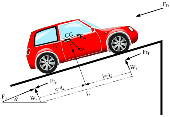
Figure 1.
Physical modeling of the vehicle forces.
In the following, the mathematical modeling for each force has been provided. The first one is air resistance which impacts the energy required to overcome drag and is achieved by the following equation:
where specifies the drag coefficient, specifies the speed of the vehicle, represents the air density, and represents the car’s cross-sectional image within the speed direction. The second one represents rolling resistance, which affects the force needed to move the vehicle. This can be formulated as follows:
where describes the tire’s coefficient rolling resistance, and specifies the vehicle weight. The next case is the force image of weight within the motion direction that models the effect of gravity on inclined surfaces, i.e.,:
The other case is inertia force that captures the inertial force during acceleration or deceleration. This is formulated by the following equation:
where and specify the mass of vehicle and the rotational inertia weight that equals the system, respectively. By combining these forces to calculate the total mechanical driving force required for propulsion, we have:
where and represent the efficacy of the gearbox and the differential while possessing a differential of mechanics, respectively. The total force, , can be used to calculate the required motor torque T by the following:
where specifies the wheel radius. The required motor power can then be calculated as:
where ω defines the angular velocity of the motor. Also, the relationship between current, voltage, and motor speed using standard motor equations is formulated as follows:
where represents applied voltage, states the current, signifies the armature resistance, defines back EMF constant, and stands for angular velocity. Figure 2 shows the model of motor dynamic.
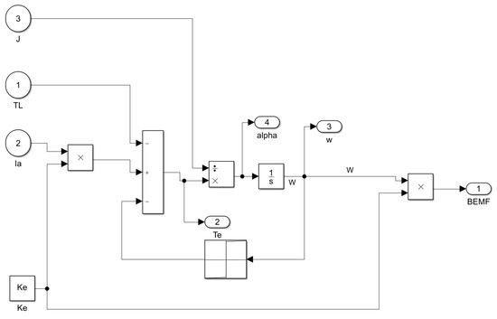
Figure 2.
Motor dynamic modeling.
The main features of the model are given in Appendix A.
3. Photovoltaic (PV) Systems and Energy Storage Batteries
The goal of retiring a photovoltaic (PV) system autonomously with an EV is to enable the EV with a sustainable and reliable power source to improve the overall performance and independence of the EV. Solar panels are the basic elements of a PV system (utilizing the PV effect, converting light to electrical energy). This electricity is saved in energy storage batteries, which power the engine of the EV and other electric parts. Solar PV panels consist of some solar cells that produce this electricity by generating a small voltage and current when exposed to sunlight. The resulting output of these cells is a volt and current usable to charge the batteries [15]. Figure 3 shows the simulated system of PV.
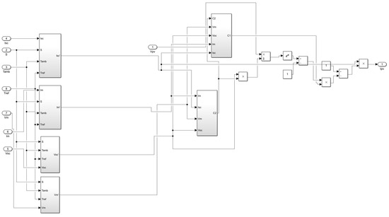
Figure 3.
The model of the simulated PV system.
The PV system model is a really sustainable means of providing electricity for charging the batteries of EVs while ensuring the reduction of reliance on grid electricity and maximization of the efficiency of the entire system. Solar panels made of semiconductor-based solar cells are included in the PV system to directly convert that sunlight into electrical energy through the PV effect. The environmental conditions that will affect the output of the system are solar irradiance and temperature, where higher irradiance produces more power, while increased temperatures slightly decrease voltage output. To fully harness power under changing conditions, the system is coupled with a maximum power point tracking (MPPT) mechanism, in particular, the Perturb and Observe (P&O) method which dynamically adjusts the operating point of the PV array to facilitate maximum energy extraction.
An energy storage battery is usually made of lithium-ion due to its high energy density and efficiency which acts as a buffer to store the excess energy obtained during high irradiance periods and supply energy during low irradiance periods/high power demand periods for continuous power for EV operations, even in absence of sunlight, efficiently and reliably working around the proposed control framework for EVs. Also, energy storage batteries are commonly lithium-ion because of their high energy density, efficiency, and service life. One vital metric that describes the remaining capacity of the batteries is their state of charge (SOC). The energy storage batteries are designed to serve as a buffer, which stores excess energy produced by the PV panel during high irradiance time and provides energy to the motor during low irradiance or high-power periods.
The PV system and battery storage are all effectively integrated and coordinated on a single dynamic-model system level to provide maximum energy supply by ensuring varying load level energy generation, storage, and consumption balance. In such periods with low load and high solar irradiance, the PV system will produce surplus energy that can be stored in the battery so as not to waste and to be available later. When there is an increase in the load, or if solar irradiance decreases (if it is cloudy or at night), the battery provides energy to cover the load demand and operate the EV motor [16]. This setup proves particularly useful when operating in high load conditions due to the instantaneous discharge of battery output to combat lowered output from the PV system whilst during medium or low load; the PV system can recharge the battery directly or power the motor. Utilizing advanced control strategies, including an IPO, the system optimizes power flow through the system and decreases dependence on grid electricity, improves voltage level stability, and enhances the efficiency and reliability of the EV powertrain during a broad spectrum of operating conditions.
4. The Improved Parrot Optimizer (IPO)
Studies have highlighted four primary behaviors characteristic of the Pyrrhura molinae parrot: foraging, communication, wariness of unfamiliar individuals, and resting. These behaviors serve as the foundation for the development of an algorithm that takes into account the parrot’s distinctive attributes. For instance, during foraging, these parrots collaborate to locate food, employing their olfactory senses and visual indicators to identify nourishment, while also enhancing their strategies by considering the positions of their owners and peers. Furthermore, they engage in social interactions through vocalizations, producing various sounds to connect with others and fulfill social objectives. Additionally, they exhibit a natural apprehension towards strangers, often seeking solace by remaining close to their owners. The unpredictability of these behaviors can influence the algorithm, as they manifest randomly in each cycle.
4.1. The Original Version Conception
The initialization procedure is characterized by an equation that incorporates various essential parameters, such as the maximum number of iterations (max_iter), the number of candidates (N), and the upper and lower limits (ub and lb):
where describes the number of individuals, is a random value between 0 and 1, and and represent the lower and the upper bounds, respectively. In this optimization process, the candidates anticipate the location of the food based on their owner’s circumstances through foraging. Subsequently, they proceed to the anticipated location. Their actions are also calculated using the following equation:
where signifies the best position found so far by any candidate in the population, specifies the Levy flight distribution which introduces randomness into the search process to enhance exploration, represents the maximum iteration of the process, defines the mean value of the position at iteration , and and represent the candidate’s current situation and updated position, respectively.
The optimizer’s population mean position is represented by , while the Levy distribution, , is used to describe the candidate’s flock behavior. The best position found so far is , and the current swarm position is denoted as it. The current iteration is represented by , and the animals’ movement towards the owner’s position is calculated using the equation . The candidate’s position is discovered using a combination of randomization and the mean population position, represented by , which helps determine the direction of the nutrition source. The average position of the existing population is represented by , which is defined mathematically as follows:
Furthermore, the distribution of is derived using the following formula, with a value of 1.5 established for :
At this stage, such amicable candidates are capable of traversing various regions of the owners’ bodies, as determined by the following equation:
The movement of the flock towards the host is depicted by . The random flight to various regions of the owners’ bodies is represented by , while signifies a vector consisting entirely of ones in one dimension. The candidates interact with others to gather in a location and move towards the group. Here, their behaviors have similar probabilities with the mean population position representing the center of the group which is computed as follows:
where expression (1) is the process that the individuals become a part of the group for communicating, and expression (2) defines how the candidates become far away after communicating. The inclination of these candidates to evade unfamiliar individuals and search for security with their owners to identify a safe environment is assessed using the following formula:
4.2. The Contributions on the Original Version
The stochastic choice of the individuals during the iterations may occasionally result in premature convergence, thereby extending the running time. However, this issue can be mitigated through the implementation of mechanisms like the Lévy flight (LF) mechanism. This widely recognized technique for improving meta-heuristics is founded on the principles of random walk behavior, which aids in managing and optimizing the local search position. Occasionally, throughout the stochastic selection of the individuals within the iterations, early convergence resulted that raises the time of running. Some approaches exist for enhancing optimizers. Lévy flight (LF) has been considered a popular approach for enhancing the optimizers [17]. The LF is based on a random walk manner for controlling the exploitation in the following way:
where the function of Gamma has been expressed by , illustrates the [18], and , and w displays the size of step. Hence, the upgraded plantation based on has been gained subsequently:
where represents the inertia weight that balances exploration and exploitation with a fixed or adaptively adjusted value during iterations. Additionally, the “” stays unchanged, specifies a scaling factor or step size controlling the magnitude of the adjustment, and represents the difference vector guiding the direction of movement. Therefore, it cannot have improvements, which may get stuck in local optima. To address this issue, the theory of Chaos is utilized. The chaos is computed using the subsequent formula:
Here, m illustrates the dimension of the map, and can determine the chaotic model’s function of the generator [19]. A sinusoidal chaotic map has been employed for enhancing the performance of SFO regarding convergence using the formula provided below:
where k describes the number of iterations.
In the original PO, the foraging mechanism is based on the Levy flight, which can lead to slow convergence. To overcome this, we introduce a new foraging mechanism that combines the benefits of Levy flight with the exploitation capabilities of the particle swarm optimization (PSO) algorithm. The updated foraging mechanism is given by:
where provides the updated position of the i-th candidate at iteration t + 1, is the current position of the i-th candidate at iteration t, and specifies the best position found so far in the population. represents the Levy flight distribution for exploration, is the inertia weight, is the cognitive parameter, stands for a random number uniformly distributed between 0 and 1, and specifies the dimensionality of the optimization problem.
The initial proposal employs a communication mechanism grounded in a static probability. This approach, however, may result in premature convergence. To mitigate this issue, an adaptive communication mechanism has been proposed that modifies the probability following the iteration number. The revised communication mechanism is articulated as follows:
where is a random number between 0 and 1, and is updated as follows:
In the initial version of the model, the fear of stranger mechanism relies on a basic cosine function. This approach, however, may result in oscillatory behavior. To address this issue, we propose a revised fear of stranger mechanism that employs a sigmoid function to create a more gradual movement. The newly formulated fear of stranger mechanism is expressed as follows:
where sigmoid .
The Boosted Parrot Optimizer (BPO) presents numerous enhancements over the original Parrot Optimizer (PO) algorithm. By integrating the advantages of Levy flight with the exploitation strengths of Particle Swarm Optimization (PSO), the BPO also incorporates an adaptive communication mechanism and an enhanced fear of stranger mechanism. It is anticipated that the BPO will surpass the performance of the original PO algorithm across a range of optimization challenges. The Boosted Parrot Optimizer is used for optimal selection of the hyperparameters and providing minimum cost function in order to improve SE for the classification assignment. By adjusting hyperparameters and managing the training process through techniques like cross-validation and early termination, the SENET achieves effectiveness and better generalization.
The main contributions of the proposed IPO algorithm include the design of Intelligent Lévy Flight and Chaos Theory to improve the exploration and exploitation ability of IPO so that the algorithm does not prematurely converge and can effectively escape the local extreme point (LF has the global search capability, and the random walk with a heavy tail is undetermined and can optimize the search space; Chaos Theory can ensure the diversity of LEVY flight and smooth convergence). It also uses an adaptive communication method, updating probabilities with iteration numbers for the trade-off of exploration and exploitation. This work enhances the original Pigeon Optimization’s foraging mechanism with a fusion of Particle Swarm Optimization (PSO) to increase the convergence speed and accuracy and substitutes the primitive cosine-based fear-of-stranger mechanism with a sigmoid function to enable a gradual and smooth movement to an optimal solution. The IPO is uniquely developed and applied to EV voltage control by integrating with PID controllers and PWM techniques for EV motor control, which is an innovative approach to control theory design in this area.
The IPO algorithm proposed in this paper can dynamically adapt motor control parameters of EV according to the influences of temperature changes and different driving cycles on the EV motor performance. Temperature changes can affect the motor’s electrical resistance, efficiency, and torque output and driving cycles introduce varying load demands that affect speed and stability. Fortunately, to overcome these concerns the IPO algorithm dynamically adjusts the PID control based on the feedback parameters (Kp, Ki, Kd) to allow for reliable voltage control and energy usage as the scenario changes. Through a clever algorithmic exploring approach, including Lévy Flight and Chaos Theory concepts, exploring all solutions hopes to achieve control values that can lead to the least error such as overshoot, settling time, and a steady state value.
The ability to learn and adapt guarantees stable motor performance under environmental and operational uncertainty, thus, the system becomes resilient to parameter shift due to temperature and varying driving profiles typically associated with real-world driving. The IPO algorithm optimizes the voltage regulation and control of EVs under ever-changing environmental conditions, such as temperature, solar irradiance, and driving cycles. The IPO algorithm essentially optimizes the parameters of a proportional integral derivative (PID) controller incorporated with Pulse Width Modulation (PWM) techniques to control motor voltage and enhance overall EV performance and energy efficiency.
To allow sustainable power and stable supply, the system further adapts PV technology, incorporating lithium-ion battery storage to minimize dependency on the grid for its operation. The PV system comprises solar panels that harvest sunlight energy and store the surplus in batteries for utilization during periods of low irradiance or excess demand. The Perturb and Observe method of the Maximum Power Point Tracker (MPPT) algorithm was used to maximize energy extraction from the PV unit under varying irradiance conditions. Algorithm 1 shows the pseudocode for the IPO for PID Tuning.
| Algorithm 1: Pseudo-Code for the IPO for PID Tuning |
| Input: - Population size N - Maximum iterations max_iter - Search bounds: lb (lower), ub (upper) - Objective function F (e.g., ITAE) - PID parameter space: [Kp, Ki, Kd] Output: - Optimal PID parameters: [Kp*, Ki*, Kd*] Initialize population P[i] randomly within bounds [lb, ub] for i = 1 to N Evaluate fitness of each individual using F FOR t = 1 to max_iter DO Compute population mean position (P_mean) FOR each individual P[i] in population DO • Foraging behavior: Update position using a fusion of: - Lévy Flight (for global exploration) - PSO-inspired update (for exploitation) • Communication behavior: - Apply adaptive communication based on iteration progress • Fear of strangers: - Use sigmoid-based movement to control randomness near local optima • Chaos enhancement: - Inject chaotic variable into the position to maintain diversity • Ensure bounds [lb, ub] are respected • Evaluate new fitness F(P[i]) IF F(P[i]) better than personal best THEN Update personal best ENDFOR Update global best if any P[i] improves it ENDFOR Return best PID parameters [Kp*, Ki*, Kd*] from global best |
4.3. Computational Complexity
In this case, N stands for the number of search agents, D means the number of PID parameters (i.e., dimensions), T is the maximum iteration time, and F is the cost of fitness evaluation per agent. Thus, the total computational complexity can be given as , where the first term is related to updates of the position, velocity, and perturbation of each agent, and the second term accounts for the cost of the fitness evaluation for all agents. Thus, the scalability of the approach remains practical, since complexity in both dimensions and agents are linear, further favored by possible parallel execution across agents.
5. Control Strategy
5.1. Pulse Width Modulation (PWM) Technique
DC (direct current) motors are popular in many applications because they are simple, reliable, and easy to control. Being able to finely tune the speed and torque of a DC motor is critical to many commercial and consumer applications. One of the most significant techniques of controlling DC motors is PWM. Pulse-width modulation (PWM) is a method employed in the control of the average voltage supplied to the motor by changing the duty cycle of a digital signal. By switching power transistors on and off at a very high frequency, the average power delivered to the motor can be changed, which controls its performance and speed. The average voltage applied to the DC motor is controlled by the switching of power transistors in a three-phase full-bridge. This configuration allows the motor to spin in both directions. In PWM control, the main parameter is the duty cycle, which is the ratio of the period when the transistors are turned on (), and the total period of the PWM signal (). Therefore, the equation for the duty cycle () is as follows:
Modifying the duty cycle allows for the regulation of the average voltage () supplied to the motor. Specifically, an elevated duty cycle leads to a greater average voltage, thereby enhancing the motor’s speed. Conversely, a diminished duty cycle results in a lower average voltage, which in turn slows down the motor. By modifying the duty cycle (), it is possible to regulate the average voltage (Vavg) supplied to the motor:
In this context, specifies the input voltage. It supplies 400 V DC to the motor from the EV lithium-ion battery pack. The voltage could drop when there is heavy current demand, such as during acceleration or uphill driving. Under such conditions, internal resistance effects might bring voltage down to as low as 360 V. On the other hand, during regenerative braking, along with charging phases with high solar PV input, and when the battery is close to full, the voltage can go up to around 420 V. This voltage is the primary supply for the motor drive circuitry and is governed through a PID controller optimally tuned by the IPO algorithm. Through PWM techniques, the voltage gets regulated so that the average voltage applied to the motor meets the needs of efficiency and stability concerning variation in driving scenarios and external parameters like temperature and solar irradiance. The three-phase full-bridge configuration employs transistors to manage both the direction and the amplitude of the voltage supplied to the motor. This arrangement facilitates bidirectional control and enhances the efficiency of motor speed regulation.
5.2. PID Controller
A proportional integral derivative (PID) controller is a common control strategy used in industrial and vehicle applications because of its simplicity and effectiveness. The PID controller continuously calculates an error value () as the difference between a desired setpoint () and a measured process variable (). The controller corrects based on three terms the proportional (), integral (), and derivative () terms:
where describes the duty cycle in PWM, and , , and represent the proportional, the integral, and the derivative gains. The objective of the PID controller is to reduce the error by modifying the control input. In the realm of PWM control for direct current motors, the PID controller manages the duty cycle to attain the target motor speed and operational efficiency.
5.3. Integration of IPO Algorithm with PWM Control Strategy
To enhance the efficiency of the DC motor, the new PWM control strategy is integrated with the IPO algorithm. The IPO models are used to optimize the PID controller’s parameters (, , ). The optimization is to minimize an objective function related to the control performance index, such as steady-state error, overshoot, and settling time. Figure 4 shows the structure of connecting the PID alongside PWM to the motor for optimal control of its voltage. The IPO algorithm continuously evaluates the control system’s response and adaptively tunes the PID gains in real time to account for varying operating conditions. This adaptive approach helps maintain precise voltage regulation despite disturbances or parameter changes in the motor or external environment. By integrating IPO-based optimization with PWM, the system achieves faster response times, reduced energy losses, and improved dynamic performance. The structure shown also supports scalability, making it suitable for different motor ratings and EV architectures. The integration of IPO with PWM and PID control offers a powerful and intelligent solution for advanced electric drive systems.
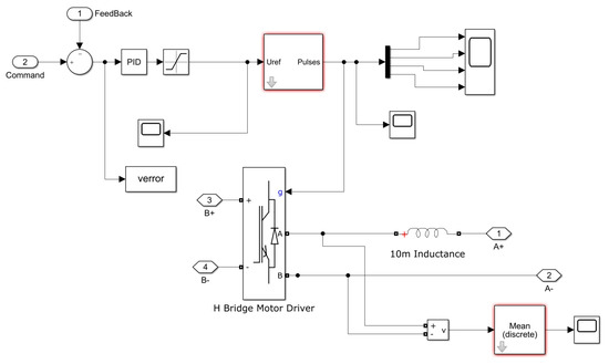
Figure 4.
The structure of connecting the PID alongside PWM to the motor for optimal control of its voltage.
Informally, the rod diagram of the PID controller connects with the motor through PWM to optimize the current–voltage control, where A is for the H-bridge input and B is for the output. That is referred to as A-H, where A refers to the digital PWM signal produced from the PID controller, which sets the duty cycle to regulate the average voltage fed into the motor via the controlled switching sequence of those H-bridge transistors; the signal operates at such a high frequency to feed the motor, smoothen out the motor’s operation, and reduce any resultant noise. The signal B represents the actual pulsating DC voltage waveform fed to the motor after the modulation performed by the H-bridge that drastically influences motors in terms of speed and torque, ensuring that under different load conditions, the motor receives controlled power for the application and withstanding efficient and stable operation [20]. This configuration allows the IPO-optimized PID controller to vary the duty cycle with hostile feedback so that it vigilantly controls the voltage and is robust to disturbances like changes in temperature and driving cycles.
The IPO algorithm works in the following steps:
- -
- Initialization: A population of candidate solutions is created (parrots) where each of these represents a set of PID parameters (Kp, Ki, Kd);
- -
- Fitness Evaluation: Each candidate solution’s fitness is evaluated using the objective function related to the control performance of the PWM-controlled motor;
- -
- Parrot Communication: Parrots communicate the position information (PID parameters) and move to the best point found up to that;
- -
- Search Mechanism: The IPO algorithm has a search mechanism that iteratively updates the position of the parrots and explores the solution space in search of optimal PID parameters;
- -
- Termination: The algorithm stops when a stopping condition is met, for example, a maximum number of iterations or convergence to an optimal solution.
The PWM control strategy is then applied with the improved PID controller tuned by IPO. It can be noticed that this adaptation made in the duty cycle allows to keep the RPM motor accurate to whether the location of the rotor changes. With the adoption of the IPO algorithm in conjunction with PWM control, this strategy further enables adaptive and robust motor control with a proven track record against parameter variation and disturbance rejection. By employing the IPO algorithm, the proposed control strategy enhances the efficiency and reliability of the DC motor control system by guaranteeing optimal efficiency in different operating conditions.
6. Results and Discussion
6.1. System Structure
MATLAB R2019b was used in Windows 10 64-bit with 12 GB memory on a CPU with Intel® Core™ i5-12600 (manufactured by Intel Corporation, Santa Clara, CA, USA) and a GPU NVIDIA GeForce RTX 3060 (manufactured by NVIDIA Corporation, Santa Clara, CA, USA). The suggested IPO algorithm will be used to adjust the voltage to attain this aim. The IPO algorithm will optimize the PID controller settings. Finding an objective function for optimum controller selection is another challenge as our goal has no equivalent scenario. Figure 5 shows the overall model of the proposed model.
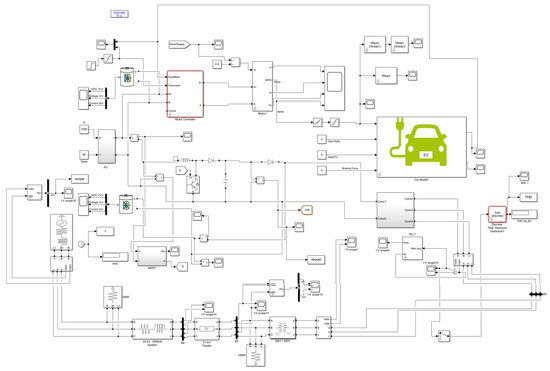
Figure 5.
The overall model of the proposed model.
As shown, Figure 5 is the complete model of the proposed EV voltage control framework, which combines a PV power source, energy storage batteries, and an Intelligent Controller using the IPO algorithm. This diagram shows how the core components will operate in a bidirectional flow of energy and information: the PV array generating renewable energy, depending on environmental conditions such as solar irradiance; the lithium-ion battery bank for storing excess energy to be used later in low irradiance or high demand periods; and the EV powertrain system (including the motor drive system regulated by a PID controller optimized using IPO). Such blocks interact with a real-time control strategy through which PID parameters are adjusted dynamically to maintain voltage levels fed to the motor under various driving conditions as well as under dynamically disturbing environments. There is also an MPPT block that makes sure that the PV system operates at maximal performance at any given moment in time.
An interface of the two components is the DC–DC converter and inverter, whether with the motor’s power requirements [21]. This is to create a single and efficient architecture that will utilize energy for multiple activities, minimize reliance on the grid, and improve both stability and response of the EV under dynamic load changes [22]. Wind, solar, and other renewable energy sources have become more popular for electricity production in recent years. PV cells convert sunlight into electricity. PV panels directly generate electricity. Photoelectricity is the basis of this technology. Thin semiconductor layers form PV cells. When light hits the crystal, its electrons generate a potential difference between the cell’s upper and bottom sides. Solar panels are constructed of solar cells joined together.
PV systems maximize energy using MPPT blocks. MPPT is used to achieve this point and maximize solar battery efficiency following the sunlight’s angle that shines on them and to follow the angle of the sun to maximize solar cell efficacy. So, each panel faces the sun throughout the day all the time; moreover, as the sun moves in the sky, so will the panels’ location. Thus, sunlight always hits the panels perpendicularly. It increases panel efficacy from 5% to 25% within a normal mode. Altering the cell’s light intensity modifies its electron production and electrical properties. Combining a solar system with different power sources reduces power losses and improves power reserve dependability. A power grid-connected electric automobile and solar system were employed in this investigation.
Electric automobiles can automatically store and navigate using battery energy. In this study, a solar network with an output power supplied energy to the power grid and electric car in addition to modeling it. The PV system improves the electric car power grid and power supply dependability. The battery supplies the car’s electricity, while an inverter connects the solar system to the grid. Since the solar system generates DC electricity and has a restricted output voltage, the DC–DC converter boosts it to the three-phase inverter’s value. Because the energy supply and charging of the engine of an electric car is DC, the PV can produce electricity from DC and maintain it within the battery, which is utilized to store extra energy during solar radiation. Saving PV panel surface temperature and light radiation increases efficiency and power generation. This study adjusts electric car engine voltage via a control mechanism.
PID controllers regulate voltage. The controller adjusts motor voltage once the error signal passes through. Optimization techniques were used to find the best controller settings. This study uses the IPO algorithm to identify PID controller values and solve complicated mathematics and engineering issues. Next, a three-phase source, transformers, and transmission line linked to system loads are simulated to mimic the power network. The EV’s voltage is controlled by the PID controller to avoid excessive harmonics. The IPO algorithm enhances the controller parameters. The equation for optimizing the engine controller’s objective function:
where describes the control error at time . Integrating the time of simulation (t) by the absolute value of the speed of engine signal distinction yields the recommended cost function. For the least cost function, the desired controller settings are ideal. The IPO adjusts dynamically to implement the three gains of the PID controller, namely , , and , which influence the motor voltage , current , and angular velocity ω according to Equation (30):
In this equation, R is the armature resistance, and Ke is the back EMF constant. The IPO algorithm optimally tunes these PID parameters through an objective function that minimizes error metrics like overshoot, settling time, and steady-state error, thus enhancing the torque T of the motor expressed as (31):
Thus, it becomes a constant irrespective of the load condition arising from the dynamic driving cycles and environmental influences such as temperature. Optimized PID values also affect the duty cycle of the PWM signal, which otherwise adjusts the average voltage supplied to the motor:
where stands for input voltage. This affirms the intelligent incorporation of the IPO mechanism in adapting on-the-fly motor control parameters to ensure perfect operation in a different place by directly interpreting the output to a parameter defined in the control loop managing EV motor dynamics.
6.2. Results Analysis
We examined the EV model, power grid, solar system, and other devices of the researched model by inserting the controller values via the proposed IPO algorithm. The MPPT system outputs 100 kW, according to assessment data. Inverter output harmonic distortion and system frequency variations were reduced by an inverter and associated electrical gadgets. Voltage increased with efficient electric vehicle controller operation. Below are the IPO simulation results for the whole system.
To find the best fitness function, which is the goal of the IPO method, we tested the ITAE (a performance measure) over different numbers of tries: 50, 100, and 150. Table 1 shows how well the IPO-optimized PID controller performed with different goal functions. The ITAE gave the best results, with the shortest settling time, lowest peak overshoot, and fastest rise time compared to the other two standard goal functions. The performance of the EV battery charger was tested using MATLAB, and the outcomes are shown in Table 1.

Table 1.
The output performances of the EV battery charger.
Table 1 presents the performance metrics of the EV battery charger as some iterations are changed. Charger-low kp and ki but high kd although no overshoot and moderate rise time and settling time at 50 iterations. The values of () and () decrease noticeably as the iterations reach a hundred iterations, displaying significantly reduced rise and settling times showing better performance and stability. Again, specifically at 150, the values of () and () stabilized, dropping () further, where we saw an overshoot, but the fastest rise and settling time of the iterations. The integral of time-weighted absolute error (ITAE) achieved its smallest value for 100 iterations, indicating that this number of iterations is the best trade-off between performance and stability for the EV battery charger. The results represented in this table should help decide on average convergence over the iterations, where it seems that only with increasing iteration number does the performance of the charger improve in the overall view, and that 100 iterations is the optimal number for minimizing the errors and at the same time achieving the most efficient charging.
Diagrams show the output assessment findings of the system’s components after simulation. Initially, the results were acquired for the PID controller settings using the given method. Below are analytical diagrams about the simulation system using the optimum controller. To provide a fair analysis, the proposed algorithm results were compared with the original Parrot Optimizer and also with the invasive weed optimizer [2]. Figure 6 illustrates the electricity generated by the PV system.
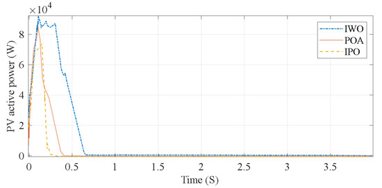
Figure 6.
The electricity generated by the PV system.
The enhanced IPO algorithm demonstrates the quickest stability in achieving the required and stable active power value, while the POA technique exhibits a delayed response, characterized by multiple successive swings before attaining a constant value due to its inherent distortions. The IWO algorithm yields a mean outcome between 2 controllers. The power of output of the PV system (IWO) originally reached around 73,780 kW, then declined to around 0.5 kW over time. Figure 7 illustrates the mechanical torque diagram of the engine of an EV.
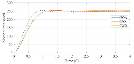
Figure 7.
The mechanical torque diagram of the engine of the EV.
As can be seen in the results, the output speed of the electric motor attains its approximate highest value of around 32 rpm after the first 0.3 s and settles at a steady-state value of 248 rpm with minimal settling time and overshoot. In terms of the transient phase, the IPO algorithm presents a lower overshoot than other optimization techniques like the original Parrot Optimizer (PO) and the Invasive Weed Optimizer (IWO). This means the IPO algorithm is quite successful at reducing any oscillations and converging towards the target speed in a smooth manner, which is an important property, by taking the back pressure of the motor into account.
Through the critical assessment of the results, this work underpins the key role an IPO can play, adjusting PID controller parameters in real-time to enhance the system response characterized by a decrease of the overshoot. This is also true for the advanced mechanisms integrated into the IPO such as Lévy Flight and Chaos Theory which allows the IPO better exploration and exploitation than traditional algorithms. However, even though the IPO performs better regarding the stabilization time getting faster, and the torque response improving, it should be noted that the slight overshoot presented at high iterations (e.g., 150) indicates that this process can be improved and the settings of the derivative gain can be tweaked to remove the oscillation at the end of the trajectory. Figure 8 illustrates the electric cars’ electric torque diagram within various formats.
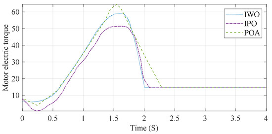
Figure 8.
The electric torque diagram.
The graph indicates that the suggested IPO method has attained a stable value of 0.8 s.
6.3. Analysis of the Proposed Control Method Under Different Solar Irradiance Levels
To validate its performance, the proposed control method was tested over a wide range of solar irradiation to analyze its response under different environmental conditions to systematically evaluate adaptability and robustness concerning real-world PV system output variability. The power produced by the PV panels is directly influenced by solar irradiance, and it ultimately affects the voltage stability provided to the EV motor. Simulations were performed at three solar irradiance levels: low (200 W/m2), medium (600 W/m2), and high (1000 W/m2). The results show that even with changes in the available energy, the voltage is stabilized, and perturbations are minimized when the PID controller based on the IPO is used. The evaluation of performance metrics like settling time, overshoot, and integral time-weighted absolute error (ITAE) at each irradiance level is depicted in Table 2.
Table 2.
The performance metrics under different solar irradiance levels.
The results indicate an increased output of the system, faster stabilization, and lower error metrics with increasing solar irradiance since there is more energy present from the PV system. The controller exhibits slightly longer settling times and increased ITAE values at low irradiance while enforcing stable operation without overshoot. This approach highlights the utility of the IPO algorithm in determining PID parameters according to different PV output values.
The proposed control method is based on the analysis of its performance at differing levels of solar irradiance which allows it to maintain consistent performance over a wide range of environmental conditions. The energy storage battery is utilized more in terms of PV energy; hence the response time is somewhat slower at low irradiance. However, with the IPO-tuned PID controller, this is guaranteed to have minimal overshoot and voltage stability even under non-ideal conditions and, consequently, with the increased PV power generation at medium and high irradiance levels, the system efficiency is increased, resulting in shorter settling times and decreased of ITAE values. The results verify that the designed control strategy is very flexible and optimizes EV performance due to the uncertainty in the availability of solar energy.
6.4. Analysis of the Proposed Control Method Under Different Temperatures
PV system performance and EV battery electrical characteristics are significantly affected by temperature fluctuations. As an assessment of the proposed control method resilience, simulations were performed under three temperature conditions: low (15 °C), moderate (25 °C), and high (45 °C). These temperatures are standard operating conditions for EVs in various environments. Table 3 summarizes performance metrics such as settling time, overshoot, and ITAE vs. temperature.
Table 3.
The results of performance metrics.
Moderate temperatures resulted in the best performance with the lowest settling time and the lowest ITAE values, as shown by the results. The system shows a slight delay in response for the avoided low temperatures since the battery does not work effectively and with the increase in the temperature, the system suffers from high thermal losses which results in higher values for overshoot and ITAE. Although these factors are similar to others, the IPO-tuned PID controller does mitigate these negative effects on voltage regulation due to temperature variations. Preferred temperatures (25 °C) help both PV systems and batteries. The cold conditions reduce the effectiveness of the battery, which slows stabilization, while heat causes thermal losses to accumulate making operation less efficient. However, since the IPO algorithm is an adaptive approach, it can modify its control properties of the PID controller online to minimize the effect of variations caused by temperature. Some of these results pave the way for including innovative control strategies for better reliability of EV systems in varied environmental regimes.
6.5. Comparative Performance Analysis of IPO with Mainstream Optimization Algorithms
To provide an all-round evaluation of the IPO and to address the lacuna in the comparison with mainstream optimization algorithms, a rigorous simulation study was carried out in which IPO was compared with other popular metaheuristic algorithms, namely Genetic Algorithm (GA), Particle Swarm Optimization (PSO), original Parrot Optimizer (PO), and the Invasive Weed Optimization (IWO). The CET was used to determine how well each compared to optimizing the PID constant values for voltage regulation in EV motor systems.
The objective function was the ITAE, which indicates dynamic environmental variations, such as temperature changes and sunlight intensity variations, for control performance in both transients and steady states. Each algorithm was run for 150 iterations with similar initial bounds for . All simulations were executed 30 times to ensure statistical relevance. Figure 9 exhibits the convergence particularity of each algorithm when the best fitness value (that is, ITAE) is plotted across iterations.
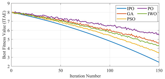
Figure 9.
Convergence comparison of IPO with mainstream optimizers.
From the figure, the IPO algorithm converges faster and attains a lower ITAE value when compared to GA, PSO, PO, and IWO. By iteration 50, IPO achieves an ITAE of around 6.21, while GA, PSO, PO, and IWO reached 7.38, 6.94, 7.56, and 7.12 values, respectively. Such trends of differences persist throughout the entire run, with IPO finally having an ITAE of 4.81 at iteration 150 while GA and PSO reach 6.49 and 5.72, respectively. The poor performances among the original PO and IWO ranked the worst in terms of the end values attained by both algorithms, which were 6.93 and 6.02, respectively. Such results show that the hybridization of Lévy Flight, Chaos Theory, and adaptive communication strategies improves exploration and exploitation capacities in the IPO to escape local optima better and move closer to optimal solutions in fewer iterations.
6.6. Evaluate the Proposed System by Simulating Different Operating Conditions
The project was extensively tested through simulations to evaluate the performance and robustness of the IPO algorithm-based PID-PWM control scheme for EV motor voltage regulation. Testing conditions were categorized into dynamic driving scenarios and asynchronous solar irradiance profiles, along with varying ambient temperatures to reflect real load conditions. The objective was to evaluate the performance of the IPO-optimized controller under varying environmental and operational conditions, ensuring motor stability, minimal error, and energy-efficient operation.
- (A)
- Variable solar irradiance levels
For the simulation, PV model plants were subjected to operation under three irradiance levels: low (200 W/m2), medium (600 W/m2), and high (1000 W/m2), representative of normal environmental conditions such as morning, midday, and cloudy weather. In the simulation setup, PV power to the EV battery was transferred with the help of an MPPT controller and DC-DC converter. To stabilize motor performance against the fluctuating solar input, an IPO was utilized for PID control of the motor voltage. The performance of the system was rated using several key indicators, including voltage deviation, overshoot, and ITAE (see Table 2).
As predicted, better performance was obtained at higher solar irradiance because of the increased availability of energy. Even when solar irradiance was low, voltage oscillations were minimized by IPO algorithm adjustment of PID gains and satisfactory motor performance was ensured. This affirms that the controller can adapt to intermittent renewable sources.
- (B)
- Temperature Variations
The endurance of the system was examined under low (15 °C), moderate (25 °C), and extreme (45 °C) temperatures. The endurance of the system is from the thermal factors for the PV array and the lithium-ion battery. It was modeled with empirical equations to assess the temperature effects on PV output and the internal resistance of the battery. The Improved Particle Optimization (IPO) algorithm was adopted for real-time returning through the feedback temperature sensor in different thermal conditions to ensure the system’s status and operation stability (see Table 3).
It showed that moderate temperature produced the optimum performance, where both PV efficiency and battery conductivity reached their maximum. At high temperatures, thermal losses caused a slight performance degradation, which was counteracted by the adaptive IPO algorithm applying online control parameter adjustment. Low temperatures delay battery response, hence increasing settling time; however, the system remained stable and exhibited no significant overshoot.
6.7. Discussion on Suitability of the Proposed Control Method for Wireless Charging Systems
This section discusses the appropriateness of the proposed IPO algorithm for WPT, presenting major attributes of WPT systems that transfer energy with the use of inductive or resonant couplings but do not require any physical contact between coils. Although these systems are afflicted with a few challenges such as precise coil alignment, power losses, electromagnetic interference (EMI), and thermal management, their efficiency depends upon coil coupling, space, and load conditions [23]. Drawing parallels between PV and WPT systems, both of which deliver sustainable energy for EVs, AC/DC power management, and presenting the power fluctuations experienced in these systems due to external conditions (solar variability for PV systems, misalignment for WPT systems). Since dynamic load conditions in WPT can destabilize voltage regulation at the terminals of the EV batteries, the IPO algorithm, which was originally designed for PV systems to tune their PID controller parameters, is proposed in this study to overcome these challenges and enhance the charging efficiency. The charging efficiency of EV batteries in the proposed system is significantly improved through the integration of PV energy and intelligent PID parameter tuning using the IPO algorithm for voltage control. Under ideal irradiance conditions (1000 W/m2), the system achieved an optimized charging efficiency of approximately 95%, as evidenced by high motor efficiency and strong MPPT performance. The PV system contributed a maximum power output of 100 kW, supporting efficient and sustainable battery charging. Furthermore, the IPO-optimized PID controller effectively minimized energy losses during voltage regulation, resulting in an ITAE as low as 4.92 at high irradiance, which reflects precise, stable, and low-error control. These findings confirm that the proposed control strategy enhances both the efficiency and reliability of EV battery charging, particularly under favorable solar conditions and with the aid of adaptive optimization techniques.
Nevertheless, certain WPT challenges, including sensitivity to misalignment, high-frequency power electronics, and thermal management require additional feedback loops, frequency-domain optimization, and thermal monitoring integration [24]. This is a question of how to carry out adaptive PID auto-tuning in dynamics to exactly match the purpose of WPT system adjustment to validate the algorithm with some existing technologies, such as LCC/LCC compensation topology. To increase efficiencies, modifications such as adding real-time feedback sensors, constructing hybrid energy management frameworks, and expanding frequency domain analysis are proposed for the efficient feasibility of the proposed control method in various WPT systems.
6.8. Comparative Performance Analysis of IPO with Mainstream Optimization Algorithms
We wanted to prove the originality and strength of the suggested Improved Parrot Optimizer (IPO), so the comparative study was expanded to include the two most popular cited metaheuristic algorithms used in PID tuning:
- –
- Particle Swarm Optimizer (PSO): A classic swarm-based optimizer that follows flocking behavior of birds and has a rapid convergence speed but is susceptible to local optimum in complex search spaces;
- –
- Grey Wolf Optimizer (GWO): A very recent nature-based algorithm following the hierarchy of leadership and hunting behavior of grey wolves; it is favored because of its balance of exploration and exploitation.
Each algorithm was subjected to 150 iterations with 30 runs under the same conditions of PID search bounds. The objective function used was the integral of time-weighted absolute error (ITAE) for EV motor voltage control in dynamically changing conditions (see Table 4).
Table 4.
Final ITAE comparison after 150 iterations.
The IPO algorithm has bestowed upon itself gains over GWO and PSO regarding attained final values of ITAE and speed of convergence, indicating its graphical superiority in solution stability. However, although GWO performs superiorly compared to PSO and GA due to its hierarchical leadership-based exploration, the significant advantages that IPO holds are hybrid exploitation mechanisms that are widely used: PSO and Lévy flight. Also, chaos-enhanced diversity and adaptive communication features have a direct bearing on these two features, unlike in GWO and PSO, which lead to much more accurate and stable control performance, further confirming novelty and effectiveness in dynamic real-time PID tuning tasks on-board EV voltage control.
7. Conclusions
EVs are established as sustainable alternatives to internal combustion vehicles; hence, controlling strategies need to be developed to ensure optimum performance for dynamic environmental conditions and dynamic operational situations. This study proposed the Enhanced Parrot Optimizer (EPO) algorithm to improve PID-PWM control circuitry for voltage regulation of EV-type motor systems, especially when powered by renewable energy sources such as a PV system. Simulation results prove that the IPO control system was the best-performing one under varying conditions including different driving cycles, solar irradiance levels, ambient temperatures, and load disturbances. The IPO algorithm tuned the PID controller parameters in real-time thereby assessing the system in terms of critical performance values such as overshoot, settling time, and integral of time-weighted absolute error (ITAE). The IPO, in comparison to old methods of optimization such as PO and IWO, has ensured rapid convergence and better stability, an ITAE value of 4.81 being achieved after 150 iterations while significantly less than those for GA (6.49) and PSO (5.72). With the fluctuating solar irradiance (200–1000 W/m2), the IPO-based controller played a significant role in maintaining stable motor performance, with settling time interval changed from a low (1.45 s) at low irradiance to a high (0.74 s) at high values. The same performance was confirmed while heat testing under temperature variation (15–45 °C), maintaining acceptable settling time (0.91–1.30 s) and low overshoot (0.2–0.7%), which shows robustness concerning thermal effects on the PV output and battery characteristics. The integration of a PV system with lithium-ion energy storage substantially improved the sustainability and reliability of the EV powertrain. The PV–battery combined system reduces dependence on grid electricity while also cushioning against voltage fluctuations so that power will always be available with no interruption even during periods of low irradiance or high demand. The integration thus leads to improved energy efficiency characterized by a maximum MPPT efficiency of 100 kW and more stable voltage level transition in variable load. The proposed control methodology was also extended towards studying the suitability of WPT applications. Coil misalignment and thermal losses are some of the challenges related to this application; nonetheless, judging from its level of adaptability, the IPO algorithm could be considered for tuning control parameters in real-time for improved charging efficiency and system reactivity under WPT situations. In summary, the simulation results substantiate that the IPO-optimized control framework is effective in enhancing the performance, efficiency, and reliability of EV motor voltage regulation. This approach holds extreme promise for next-generation smart sustainable transportation systems. Future research will involve the hardware-in-a-loop (HIL) implementation of the IPO algorithm and further investigation into its potential for multi-EV coordination and smart-grid integration.
Author Contributions
Conceptualization, M.Y. and E.S.; Methodology, E.S.; Software, E.S.; Validation, E.S. and M.Y.; Formal Analysis, E.S.; Investigation, E.S.; Resources, M.Y.; Data curation, E.S.; Writing-Original Draft Preparation, E.S.; Writing-Review and Editing, M.Y.; Visualization, E.S.; Supervision, M.Y.; Project Administration, M.Y.; Funding Acquisition, M.Y. All authors have read and agreed to the published version of the manuscript.
Funding
This research received no external funding.
Data Availability Statement
The original contributions presented in this study are included in the article. Further inquiries can be directed to the corresponding author.
Conflicts of Interest
The authors declare no conflict of interest. The funders had no role in the design of the study; in the collection, analyses, or interpretation of data; in the writing of the manuscript; or in the decision to publish the results.
Appendix A
Table A1.
Features of the model [14].
Table A1.
Features of the model [14].
| Category | Parameter | Value |
|---|---|---|
| System | Air density | 1.2 kg/m3 |
| Power transmission efficiency | 90% | |
| Cross-sectional area (A) | 2.1 m2 | |
| Drag coefficient | 0.35 | |
| Coefficient of rolling friction | 0.013 | |
| Vehicle weight | 1800 kg | |
| Battery | Type | Lithium-Ion |
| Nominal voltage | 400 V | |
| Capacity | 80 kWh | |
| No. cells (series/parallel) | 96S/4P (96 cells in series, 4 parallel groups) | |
| Energy density | 250 Wh/kg | |
| Cell chemistry | NMC (Nickel Manganese Cobalt) | |
| Motor | Type | Permanent Magnet Synchronous Motor (PMSM) |
| Rated power | 150 kW | |
| Peak torque | 350 Nm | |
| Efficiency | 95% | |
| Photovoltaic System | Panel type | Monocrystalline silicon |
| Nominal power output | 5 kW | |
| Efficiency | 20% | |
| MPPT tracking algorithm | Perturb and Observe (P&O) | |
| Energy Storage | Battery management system (BMS) | Active thermal management, state-of-charge (SOC) monitoring |
| Inverter type | Bidirectional DC-AC inverter | |
| Inverter efficiency | 97% |
References
- Waseem, M.; Lakshmi, G.S.; Ahmad, M.; Suhaib, M. Energy storage technology and its impact in electric vehicle: Current progress and future outlook. Next Energy 2025, 6, 100202. [Google Scholar] [CrossRef]
- Arandian, B.; Akbari, E.; Sheykhi, E.; Hanifeh, S.; Rouhani, S.H.; Sabzalian, M.H. Intelligent Voltage Control of Electric Vehicles to Manage Power Quality Problems Using the Improved Weed Optimization Algorithm. In Metaheuristics and Optimization in Computer and Electrical Engineering: Volume 2: Hybrid and Improved Algorithms; Springer: Berlin/Heidelberg, Germany, 2023; pp. 79–116. [Google Scholar]
- He, L.; Mo, H.; Zhang, Y.; Wu, L.; Tang, J. Adaptive energy management strategy for Extended Range Electric Vehicles under complex road conditions based on RF-IGWO and MGO algorithms. Energy 2025, 328, 136500. [Google Scholar] [CrossRef]
- Christensen, K.; Ma, Z.G.; Jørgensen, B.N. A scoping review on electric vehicle charging strategies with a technical, social, and regulatory feasibility evaluation. Renew. Sustain. Energy Rev. 2025, 211, 115300. [Google Scholar] [CrossRef]
- Li, N.; Zhang, C.; Liu, Y.; Zhuo, C.; Liu, M.; Yang, J. Single-Degree-of-Freedom Hybrid Modulation Strategy and Light-Load Efficiency Optimization for Dual-Active-Bridge Converter. IEEE J. Emerg. Sel. Top. Power Electron. 2024, 12, 3936–3947. [Google Scholar] [CrossRef]
- Yu, J.-T.; Su, C.-L.; Rouhani, S.H.; Sadiq, M.; Elsisi, M. Allocation of Harmonic Voltage Limits for Offshore Wind Power Plants Grid Connection Impact Study. In Proceedings of the 2023 IEEE/IAS 59th Industrial and Commercial Power Systems Technical Conference (I&CPS), Las Vegas, NV, USA, 21–25 May 2023; IEEE: Piscataway, NJ, USA, 2023; pp. 1–9. [Google Scholar]
- Feng, J.; Yao, Y.; Liu, Z. Developing an optimal building strategy for electric vehicle charging stations: Automaker role. Environ. Dev. Sustain. 2024, 27, 12091–12151. [Google Scholar] [CrossRef]
- Wang, W.-M.; Zeng, H.-B.; Liang, J.-M.; Xiao, S.-P. Sampled-data-based load frequency control for power systems considering time delays. J. Frankl. Inst. 2025, 362, 107477. [Google Scholar] [CrossRef]
- Lu, G.; Lin, Q.; Zheng, D.; Zhang, P. Online Degradation Fault Prognosis for DC-Link Capacitors in Multistring-connected Photovoltaic Boost Converters Subject to Cable Uncertainties. IEEE J. Emerg. Sel. Top. Power Electron. 2024, 13, 1107–1117. [Google Scholar] [CrossRef]
- Morais, H. New approach for electric vehicles charging management in parking lots considering fairness rules. Electr. Power Syst. Res. 2023, 217, 109107. [Google Scholar] [CrossRef]
- Manickam, V.K.; Dhayalini, K. Hybrid optimized control of bidirectional off-board electric vehicle battery charger integrated with vehicle-to-grid. J. Energy Storage 2024, 86, 111008. [Google Scholar] [CrossRef]
- El Mezdi, K.; El Magri, A.; Bahatti, L. Advanced control and energy management algorithm for a multi-source microgrid incorporating renewable energy and electric vehicle integration. Results Eng. 2024, 23, 102642. [Google Scholar] [CrossRef]
- Nafeh, A.E.-S.A.; Omran, A.E.-F.A.; Elkholy, A.; Yousef, H.M. Optimal economical sizing of a PV-battery grid-connected system for fast charging station of electric vehicles using modified snake optimization algorithm. Results Eng. 2024, 21, 101965. [Google Scholar] [CrossRef]
- Huang, Z.; Shi, Y.; Liang, D. Risk Identification and Prioritization in China’s New Energy Vehicle Supply Chain: An Integrated Tanimoto Similarity and Fuzzy-DEMATEL Approach. IEEE Trans. Eng. Manag. 2025, 72, 1434–1439. [Google Scholar] [CrossRef]
- Jiang, M.; Zhang, Y.; Zhang, Y. Multi-depot electric bus scheduling considering operational constraint and partial charging: A case study in Shenzhen, China. Sustainability 2021, 14, 255. [Google Scholar] [CrossRef]
- Zheng, X.; Nie, Z.; Yang, J.; Li, Q.; Li, F. Research on load state prediction model of electric vehicle lithium battery based on Kalman filter algorithm. Int. J. Veh. Inf. Commun. Syst. 2024, 9, 276–291. [Google Scholar] [CrossRef]
- Ingle, K.K.; Jatoth, R.K. An Efficient JAYA Algorithm with Lévy Flight for Non-linear Channel Equalization. Expert Syst. Appl. 2019, 145, 112970. [Google Scholar] [CrossRef]
- Li, X.; Niu, P.; Liu, J. Combustion optimization of a boiler based on the chaos and Levy flight vortex search algorithm. Appl. Math. Model. 2018, 58, 3–18. [Google Scholar] [CrossRef]
- Rim, C.; Piao, S.; Li, G.; Pak, U. A niching chaos optimization algorithm for multimodal optimization. Soft Comput. 2018, 22, 621–633. [Google Scholar] [CrossRef]
- Li, N.; Cao, Y.; Liu, X.; Zhang, Y.; Wang, R.; Jiang, L.; Zhang, X.-P. An improved modulation strategy for single-phase three-level neutral-point-clamped converter in critical conduction mode. J. Mod. Power Syst. Clean Energy 2024, 12, 981–990. [Google Scholar] [CrossRef]
- Meng, Q.; He, Y.; Gao, Y.; Hussain, S.; Lu, J.; Guerrero, J.M. Bi-level four-stage optimization scheduling for Active Distribution Networks with Electric Vehicle integration using multi-mode dynamic pricing. Energy 2025, 327, 136316. [Google Scholar] [CrossRef]
- Chen, J.; Zhang, J.; Zhou, J.; Shi, G.; Jia, Y.; Wang, H.; Cai, X. Enhanced Modular Multilevel Converter with Multiple MVac Ports Based on Active Fundamental-Frequency Circulating Current Injection to Realize Full-Range Operation. IEEE Trans. Power Electron. 2024, 40, 5423–5439. [Google Scholar] [CrossRef]
- Luo, Z.; Zhao, Y.; Xiong, M.; Wei, X.; Dai, H. A self-tuning LCC/LCC system based on switch-controlled capacitors for constant-power wireless electric vehicle charging. IEEE Trans. Ind. Electron. 2022, 70, 709–720. [Google Scholar] [CrossRef]
- Zhang, Z.; Pang, H.; Georgiadis, A.; Cecati, C. Wireless power transfer—An overview. IEEE Trans. Ind. Electron. 2018, 66, 1044–1058. [Google Scholar] [CrossRef]
Disclaimer/Publisher’s Note: The statements, opinions and data contained in all publications are solely those of the individual author(s) and contributor(s) and not of MDPI and/or the editor(s). MDPI and/or the editor(s) disclaim responsibility for any injury to people or property resulting from any ideas, methods, instructions or products referred to in the content. |
© 2025 by the authors. Licensee MDPI, Basel, Switzerland. This article is an open access article distributed under the terms and conditions of the Creative Commons Attribution (CC BY) license (https://creativecommons.org/licenses/by/4.0/).