1. Introduction
The maritime sector is of pivotal importance to global trade, with its significance showing no signs of abatement [
1]. This heightened intensity is particularly evident over the past decade, as maritime trade has undergone significant expansion to meet the growing demands of the sector [
2]. Marine energy systems represent a foundational component of the maritime industry, operating as the predominant source of energy for both propulsion systems and onboard power generation for commercial vessels, military vessels, and offshore vessels. These systems are of strategic importance, directly affecting the operational efficiency and sustainability of marine vessels [
3]. The power system is one of the most critical systems in a marine vessel, being autonomous in nature and affecting the entire life cycle of the vessel. This system is designed to provide energy generation to meet all the functional needs of the ship. In order to ensure safe and efficient operation of watercraft, it is essential that the electrical energy obtained from the power system is of a high quality, stable, and continuous. The substandard quality of electrical energy has the potential to exert a detrimental effect on a number of factors, including the safety of navigation, the longevity of equipment, and the efficiency with which operations are carried out. It is therefore vital to emphasize the significance of the design, monitoring, and control of the power system for the overall performance of marine vessels [
4]. The International Maritime Organization (IMO) has proposed a series of regulations with the objective of reducing emissions from this sector [
5,
6,
7]. In an effort to adhere to the established regulatory frameworks, maritime enterprises within the designated sector have initiated a series of research and development initiatives [
8]. While the IMO addresses the need for regulation by attempting to reduce this growth, shipping companies are conducting more R&D studies and taking energy efficiency measures to comply with these regulations. However, the implementation of new systems is often associated with significant financial investments, while a more cost-effective approach may involve the refurbishment of existing systems. In order to reduce the environmental impacts of the maritime sector, the International Maritime Organization (IMO) has set new targets for 2023. In this regard, the International Maritime Organization (IMO) has developed two primary assessment criteria: The Energy Efficiency Existing Ship Index (EEXI) and the Carbon Intensity Indicator (CII), which are two key performance indicators that provide valuable insights into the energy efficiency and carbon emissions of vessels. These indicators offer a framework to guide the enhancement of energy efficiency and the reduction of carbon emissions within the existing fleet of commercial ships [
9,
10,
11].
In recent years, the growing global awareness of environmental sustainability and the increasingly stringent emission regulations implemented by the International Maritime Organization (IMO) have brought about a fundamental transformation in the maritime industry. However, the maritime industry has focused on the application of new technologies to reduce emissions, the use of alternative fuels, and the electrification of propulsion systems by using multiple energy sources for propulsion. In this context, the development of next-generation propulsion systems is being restructured to meet energy efficiency and low emission targets, thus supporting the industry’s sustainability-oriented approach [
12,
13]. The utilization of shaft generators on board ships confers a dual benefit, both economically and environmentally, by enhancing energy efficiency. Consequently, these systems are being incorporated with increasing frequency in contemporary ship designs [
14,
15,
16]. The integration of these generators on vessels leads to a reduction in fuel consumption and maintenance costs, while concurrently reducing cabin noise levels. This, in turn, facilitates the utilization of lower-capacity diesel generators, thereby enhancing the overall efficiency of the vessel’s energy management system. The operation of shaft generators is predicated on the direct extraction of power from the main engine. Maintaining constant voltage and frequency values at the stator output of the generator is imperative, even in conditions where the main engine speed fluctuates due to variations in sea conditions or propeller performance under water flow. In standard synchronous SG systems, an inverter is placed between the generator and the load, and this inverter is responsible for managing the entire output power of the system [
17,
18].
In this study, one of the SGs plays an appropriate role in increasing the energy efficiency of ships. They cover both mechanical and electrical loads, providing power for the reliable operation of systems through high load variation periods, which is essential for military vessels. As for other power systems on military combat ships, this depends on their operational requirements and geographical location; the performance of the aforementioned power systems varies from region to region due to frequency and voltage level restrictions [
19].
On naval vessels, 50 Hz and 60 Hz are the most commonly used system frequencies. However, the influence of different frequency levels on the performance and technical requirements of ship power systems at different efficiencies needs to be further investigated. A comparison of the advantages and disadvantages of 50 Hz and 60 Hz systems will help to develop better ship power systems that are more economically efficient.
This paper deals with a comprehensive assessment of SGs in naval vessels and looks into how different frequency systems could translate into technical and energy efficiency. Analyses carried out in MATLAB/Simulink help to identify the best design solutions for each target system and thereby optimize system efficiency. For naval vessels, the design and energy performance analysis of the shaft generator results in a reliable energy source, enhancing operational capabilities, mission duration extension, and environmental friendliness through decreasing fuel consumption. To describe this using proper metaphors, this study is going to propose frequency and voltage systems choice for naval vessels. The present paper is concerned with the following subjects:
The main contents of this article are as follows:
- 1.
The present paper sets out the design of a shaft generator intended for military applications.
The paper presents a comprehensive electromagnetic and mechanical design of a shaft generator intended for use on military ships. The generator exhibits the capability to operate in both engine and generator modes, thereby conferring a degree of flexibility upon the vessel’s propulsion system.
- 2.
Efficiency Improvement under Operational Conditions:
Following the implementation of optimized design and enhanced performance measures, the shaft generator attained an efficiency of 97%, exhibiting a power factor of 0.86. This outcome surpasses the conventional 95% efficiency typically observed in analogous systems.
- 3.
Torque and Dynamic Performance Analysis:
A detailed analysis of torque and dynamic behaviors under various load and frequency conditions was conducted to ascertain the generator’s capacity to meet the stipulated requirements for high starting torque and stable operation.
- 4.
The validation process is to be conducted across multiple simulation environments.
A comprehensive simulation study was conducted utilizing ANSYS/Maxwell software for electromagnetic design and MATLAB/Simulink software for system-level dynamic modelling. Operational scenarios were realistically verified.
- 5.
The application’s implementation on a real military platform, in conjunction with the confidentiality scope, is a subject that merits further investigation.
The developed system has been deployed in a real-world setting on a military naval platform. Despite the fact that the system visuals were not disclosed due to military confidentiality, the design parameters and performance values employed in the study reflect the real system and reveal direct applicability for the defense industry.
2. Ship Electrical Power System Structure
According to that, the continuous development and progress of electrical and electronic engineering on ships has changed to a great extent in the installation of ships’ electrical power systems.
Figure 2 on the overview of three-phase ship’s electric power system includes diesel generators (DG), SG, other types of gensets, turbine generators, emergency gensets, submersible transformer room, load center with relays and power cables, as well as consumers [
20].
In ships that are equipped with electric propulsion systems, it is customary for the propulsion motors to be located at the main busbar systems. The utilization of power converters on such vessels magnifies the significance of power quality concerns in comparison to conventional ships [
21]. The ship’s power systems and terrestrial power distribution circuits negate many of the consequences of poor power management on the ship.
The following is a list of some of the most salient features of ship power systems:
The utilization of onboard generators imposes constraints on the available space, thereby restricting the potential for expansion.
The system under discussion must include power converters and transformers, which are essential components in the modification of voltage and frequency levels. The system incorporates a limited number of distinct capacity generators, in conjunction with major starter-control systems. The system has been engineered to ensure peak performance and efficiency.
It is imperative to acknowledge that certain power loads possess sufficient capacity to surpass the aggregate output of all installed generators when operated in conjunction.
It is evident that the short-circuit impedance of ship generators is relatively high.
Non-linear loads are a common occurrence in ship power systems.
Parallel operation of generators is possible.
Installed loads show higher sensitivity to power quality compared to terrestrial power systems [
22].
It is also important to note that ship generators have relatively high short-circuit impedance. The utilization of non-linear loads has become a customary aspect in the domain of ship power systems, facilitating parallel generator operation. Installed loads show higher sensitivity to power quality compared to terrestrial power systems. These factors require the development of special engineering approaches in the design, operation, and management processes of vessel electrical power systems.
In the domain of vessel propulsion systems, generators connected to the main propulsion shaft play a pivotal role in conjunction with generator sets, providing supplementary energy. In fixed propeller systems, the generators function at a constant speed during the operation of the main engine, thereby ensuring stable energy production, particularly in cruising mode. In propeller pitch-controlled systems, the generators can be utilized during maneuvers, provided that the engine speed remains constant.
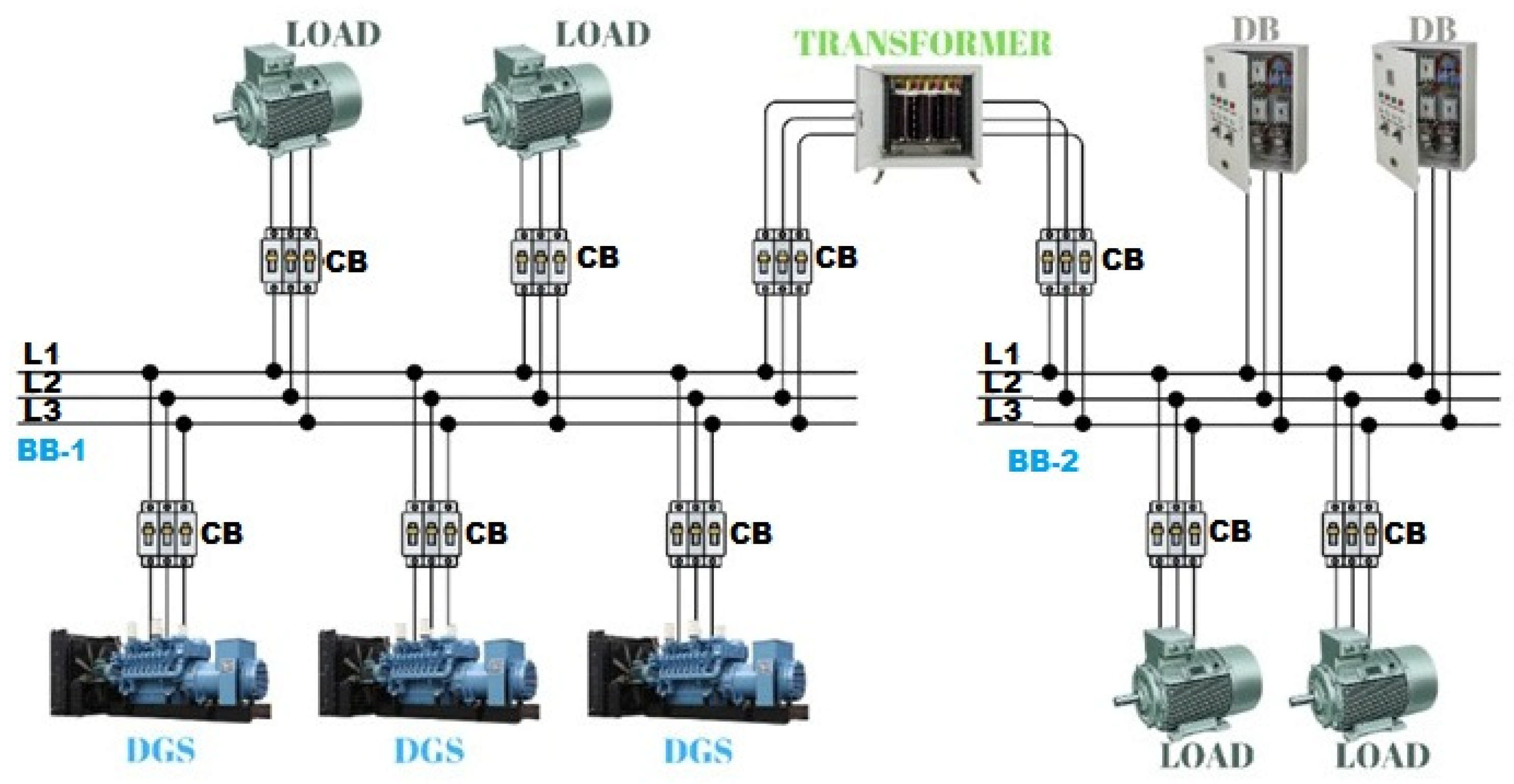
This paper provides an introduction to the fundamental principles and historical development of shipboard electrical systems that utilize three-phase synchronous generators and diesel engine-driven sets. The system is powered by two bus sections with differing voltages by three DGs. This configuration has been designed to enhance the robustness and efficiency of marine power systems. The efficacy of this configuration is determined by conducting a performance evaluation, as it is imperative that the most efficient machine in power generation and distribution is identified.
As illustrated below, a standard ship’s electrical system typically consists of a three-phase genset, driven by diesel engines, serving as the primary power source. It is important to note that the voltage rating of the two busbar sections powered by these generators is different. The DGs, in this configuration, are responsible for the generation of the requisite power. As demonstrated in
Figure 3, the system under consideration involves the generation of electricity by a generator set comprising three synchronous DGs.
Shaft generator systems have been shown to be fuel-efficient and to generate electrical power, thereby reducing the operational costs of ships. In comparison with conventional fuel-fired marine engine-generator sets, these systems offer a number of advantages in a variety of applications. These systems enhance the efficiency of the ship during operation at sea, thereby ensuring superior performance and reducing future operating costs. This paper investigates the architecture of ship energy systems with respect to shaft generator cycles for a comprehensive analysis and comparative evaluation of such systems with the operating conditions [
23]. As illustrated in
Figure 4, a system is presented in which electricity is generated by a generator set consisting of an SG and three DGs.
3. Shaft Generator System
3.1. General Specifications of Shaft Generators
Energy efficiency in the field of shipbuilding continues to be a matter of concern. The high cost of energy has prompted ship owners to purchase new vessels or upgrade existing ones in order to reduce fuel consumption [
16]. Prior to the implementation of technological solutions, it is imperative to assess the efficacy of such systems. The present study hypothesizes that ship consumers driven by the propeller shaft and powered by a shaft generator are a solution to this issue. It is acknowledged that different configurations can be used for different ship types and power plants. A generator-based solution, in particular, has been identified as a means of powering receivers, with the potential to significantly reduce fuel and operating costs by minimizing the number and hours of genset usage [
24].
The advantages of integrating an SG within the vessel’s power generation system, as contrasted with the conventional reliance on a single main engine for propulsion, are becoming clearer. This approach also offers distinct technical and economic advantages, including the utilization of the main engine in conjunction with alternative power sources to drive the generator [
25].
The introduction of the ship’s SG system dates back to its inception in 1982, with MAN B&W being among the early pioneers to explore its practical applications. Over the years, numerous models of shaft power generation systems have been developed and successfully employed in maritime operations. This innovative approach has garnered widespread interest and approval from ship owners and shipyards across the globe. The merits of integrating an SG into a vessel’s power generation system, as against relying on just a single main engine for propulsion, have become more apparent. The integration of an SG into the ship’s power generation system enables the utilization of the main engine’s power to drive the generator in combination with other power sources, thus providing both technical and economic benefits [
25].
This integration is particularly valued during extensive sea voyages, where the installed SG operates at peak efficiency. Remarkably, the power demand of a ship at sea typically accounts for only 5–10% of the main engine’s capacity. Consequently, the shaft generator optimizing surplus power reduces the workload on the diesel-driven generators and hence the fuel consumption. This contributes to the promotion of sustainability and extends the operational lifespan of the auxiliary generators. A notable advantage of shaft generators is that the cost of power production is only half that of a DG, making it a highly cost-effective and eco-friendly choice for the marine industry [
25].
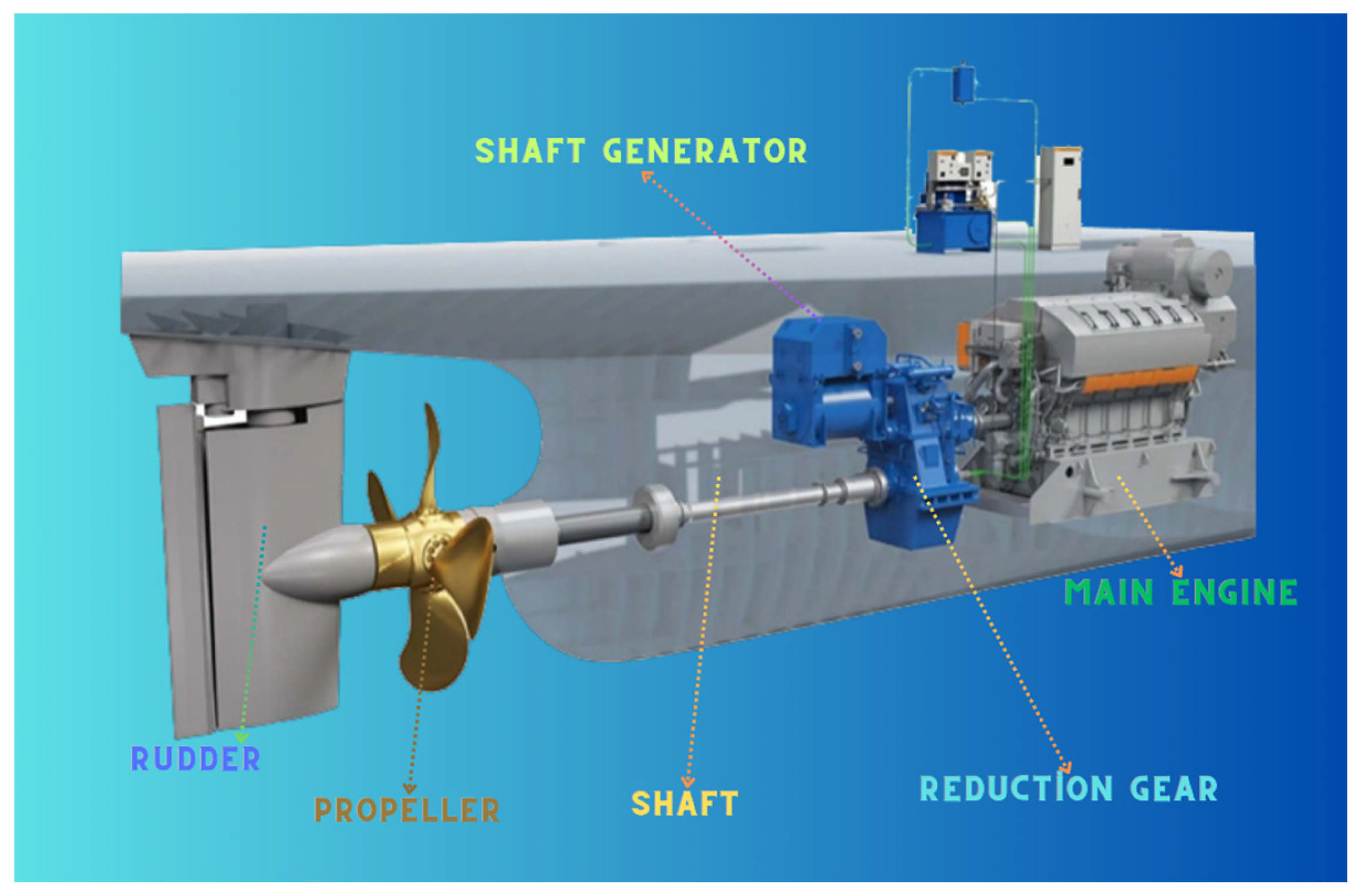
Shaft generator systems have witnessed a surge in popularity within the domain of marine propulsion, attributable to the numerous advantages they offer in comparison to conventional DG systems. The majority of SGs are mounted on the prop shaft, situated between the main propulsion engine and the propeller gearbox. A proportion of engine power is converted to electricity by some SGs. The integration of SG systems with both DG systems and other forms of alternative power sources has the potential to enhance the energy efficiency of ships. It is imperative that SG systems are meticulously designed to ensure optimal performance and efficiency. A comprehensive evaluation of the electromagnetic properties of these systems is also a crucial aspect of their assessment [
19]. As illustrated in
Figure 5, the SG is situated on a ship and is connected to the relevant systems.
Systems incorporating SGs are favored for their energy efficiency and operational advantages, offering significant benefits for ships. These systems generate electricity in a cost-effective manner by utilizing the vessel’s main engines, thereby reducing fuel consumption. The system’s compact design offers a distinct advantage in vessels where space is at a premium. In addition, the SG system offers ship owners a cost-effective solution, with low installation costs, while its lower noise levels compared to conventional generators allow for quieter operation in the vessel environment. A notable advantage of SG systems is their ability to provide an uninterrupted power supply, a crucial aspect for operational continuity, due to their high reliability [
19].
However, it should be noted that SG systems are not without their limitations. Primarily, as the ship is unable to generate electrical energy during port stays, alternative power sources are required. Additionally, the operation of the SG places an additional load on the ship’s main engine, which necessitates meticulous management. Failure to achieve so may result in adverse effects on engine performance and operational efficiency. Consequently, a meticulous design and management process is imperative, taking into account the limitations and advantages inherent to SG systems [
19].
3.2. Structure of Shaft Generator
Shaft generator systems are utilized as an efficient alternative in ship energy systems, with lower fuel consumption and operating costs when compared to conventional stationary diesel generator sets. This is due to their ability to generate electricity by taking mechanical energy directly from the main propulsion machine [
26]. In the marine industry, the term ‘shaft generator’ is used to denote an alternating current (AC) generator, otherwise referred to as an alternator. This component is powered by the ship’s primary engine. The vessel’s propulsion system comprises a drive shaft connected to the propeller, which engages a large gearbox. The gearbox is capable of accommodating supplementary auxiliary shafts, the function of which may be to drive various pieces of equipment, including compressors, hydraulic pumps, or alternators. In the context of marine engineering, it is pertinent to note that the alternator is frequently designated as a shaft generator.
Shaft generators are complex systems that convert mechanical energy into electrical energy, and their operating principles are based on certain physical principles to ensure that this conversion process takes place efficiently. Basically, SGs are based on the principle of electromagnetic induction, where the rotary motion of a motor is converted into an electric current by a combination of a magnetic field and a conductive coil. This process is based on the fact that, according to Faraday’s law of induction, a conductor will produce an electric current when passed through a time-varying magnetic field.
During operation, the motor rotates the shaft, and this rotation creates an interaction between the coils and the magnetic field of the installed rotor. The magnets on the rotor create the desired magnetic field as it rotates. This process causes the field to be interrupted by the coils, producing AC. The generated electrical current is then passed through a power electronics circuit to bring it to the required voltage level. The efficiency of these systems depends on the quality of the materials used, the design of the rotor and stator, and their placement and assembly.
In addition, SGs are supported by various control devices that provide the ability to optimize the system on the fly. For example, automatic control systems that regulate the output voltage and current increase the efficiency of SGs and provide protection in overload situations. In summary, the operating principle of SGs is both a reflection of the laws of physics and a product of modern engineering practice. In this way, the process of converting mechanical energy from both industrial and renewable sources into electrical energy is carried out with high efficiency.
As illustrated in
Figure 6, the general structure and connection details of a typical SG are demonstrated. This generator is mechanically connected to the main propulsion system and generates electricity with the rotational motion it receives from the ship’s main engine. It is evident that the SG depicted in
Figure 6 is prepared for immediate utilization, with all necessary connections having been established on board.
3.3. Shaft Generator Model and Analysis
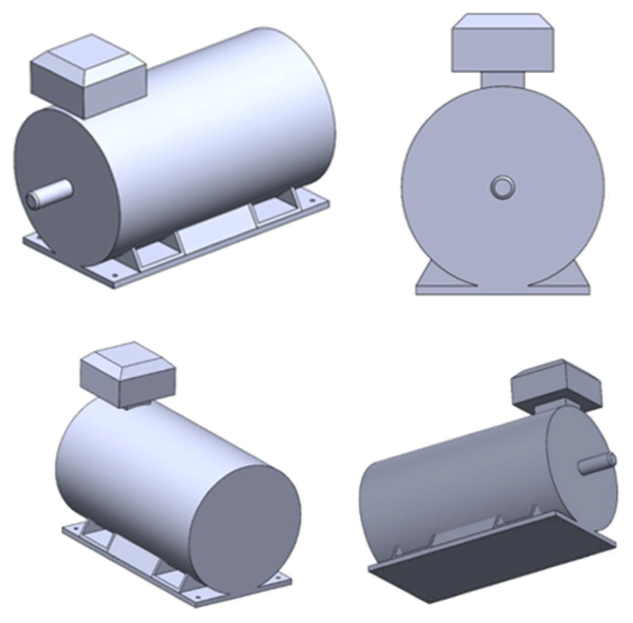
The purpose of this study is to analyze the performance of the SG under different voltage levels, output frequencies, and pole numbers in the MATLAB/Simulink environment. The analysis will encompass the electrical characteristics of the generator, with a particular focus on how parameters such as output voltage, frequency stability, power quality, efficiency, and torque generation are influenced by alterations in the number of poles and system frequency. The objective of this analysis is to ascertain the most suitable configuration of SG for use in specialized applications, such as military ships, and to optimize the system according to the operating conditions. The simulation results under different scenarios will shed light on the strategies to be followed in system design and contribute to the balance between energy efficiency and performance.
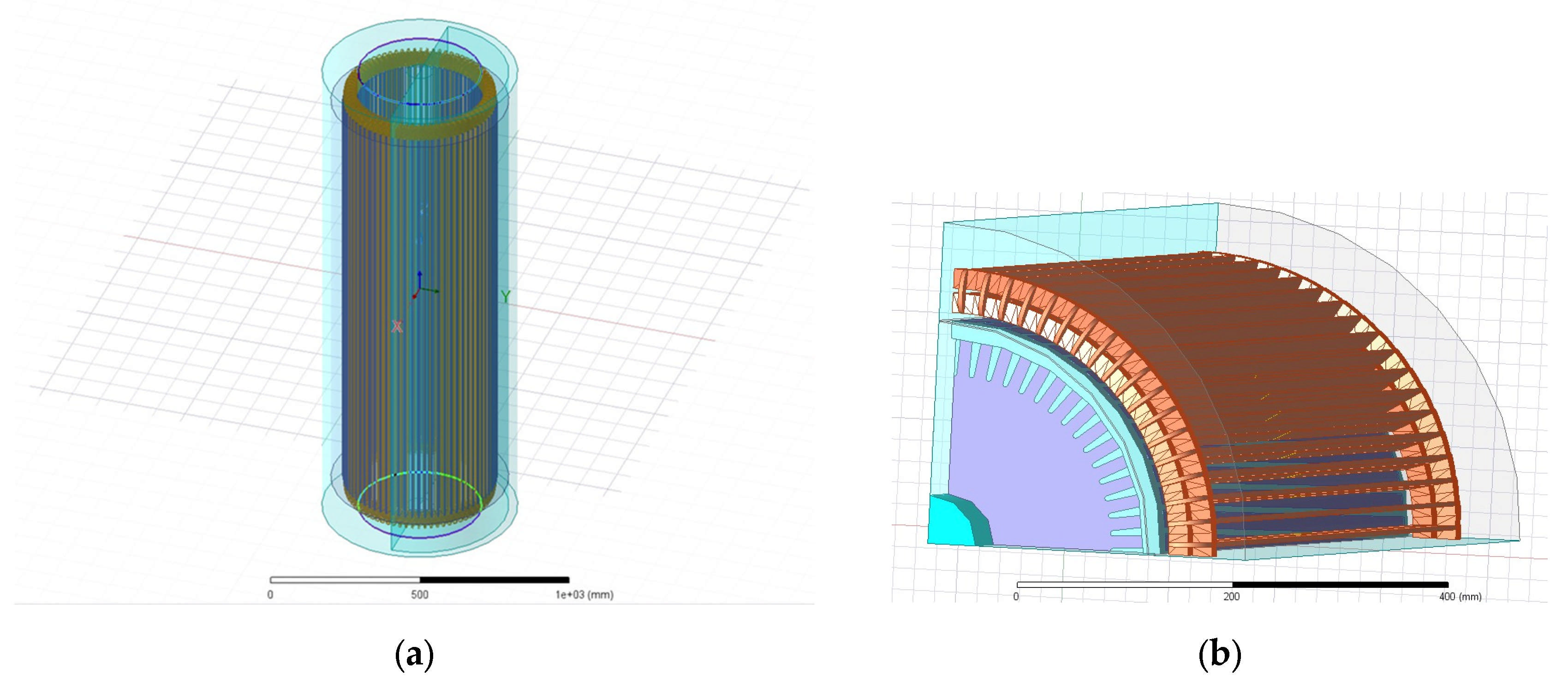
Figure 7 shows a three-dimensional model of the SG structure from multiple angles.
In addition, the shaft generator was modelled for electromagnetic analysis in the AN-SYS/Maxwell environment for better analysis. This was deemed the most suitable option due to the fact that shaft generators are electromagnetic devices, and the results of the analyses are time-dependent. The designed shaft generator model is illustrated in
Figure 8.
The rotor’s rotating field always moves behind the stator’s rotating field and is less than the rotating field speed. Stator rotating field speed is called synchronous speed (
ns) and its unit is rpm; rotor speed is called asynchronous speed (
nr). The speed difference between two revolutions is called slip (
s). It can be demonstrated that in the event of the total number of poles of the stator being
2P, the number of double poles is
P, and the frequency of the applied voltage is
f, the synchronous speed of an asynchronous motor is n
s. This equation is shown in Equation (1).
The angular velocity equation is expressed as follows
Expressing the slip speed using these values
Expressing the slip as a percentage
The rotor frequency is given as
The shaft generator model presented in
Figure 9, which was created in MATLAB/Simulink environment based on real system data, allows the basic parameters such as stator and rotor currents, voltage characteristics, rotational speed, and torque to be analyzed under varying power levels, frequency values, and operating conditions. The developed model facilitates more effective decision-making in design and optimization processes by enabling a comparative analysis of the effects of parameter variations on system performance. The overarching objective of the model is to enhance operational efficiency by facilitating a more comprehensive analysis of the dynamic response of SGs, particularly within the domains of marine engineering and electrical power generation systems.
The analyses provided by the SG model developed using MATLAB/Simulink are as follows:
The analysis of stator and rotor currents is a method by which to understand the electrical performance of the system under a number of operating conditions. Within this framework, variations in current magnitudes, frequency content, and harmonic levels are subjected to detailed analysis, with the effect of deviations and harmonics on system performance being rigorously evaluated. These analyses yield critical insights pertaining to system reliability and efficiency.
A detailed analysis has been conducted on the 690 V, 440 V, 400 V, and 380 V systems, which are commonly utilized in ship electrical systems. In the course of the investigation, a range of parameters is evaluated, including harmonic content, current fluctuations, torque, and speed stability. In addition, the system’s behaviors under a number of different operating conditions are observed, and opportunities for improving performance are identified.
The present study analyses the speed and torque behaviors of shaft generator systems at frequencies of 50 Hz and 60 Hz for different power ratings. The investigation evaluates the dynamic response, stability, and efficiency of the system and provides comprehensive insights into the effects of sudden load variations, as well as important performance criteria such as energy losses and mechanical stability.
These analyses facilitate the comparable valuation of basic electrical parameters such as stator and rotor currents, voltage profiles, speed, and torque behaviors of SG systems as a function of different power, frequency, and operating modes. The data obtained are of significant importance for the more effective design and optimization of such systems in the marine industry. The selection of appropriate equipment and components during the design process can be made in a more informed manner thanks to these multifaceted analyses, and the system can operate at maximum efficiency. Furthermore, the analysis provides a strategic framework to increase energy efficiency and reduce operational costs in the long term by preparing the ground for further studies on harmonic components and the overall stability of the system.
4. Results and Discussion
This study involves a detailed, comparative analysis of two different shaft generator systems, one with a 2-pole Squirrel Cage configuration and the other with a Double Squirrel Cage configuration that operate under 690 V voltage and 60 Hz frequency values. This analysis is conducted within the MATLAB/Simulink environment, with the primary objective of assessing the performance criteria of the two generator types and unveiling their dynamic responses under various operational conditions.
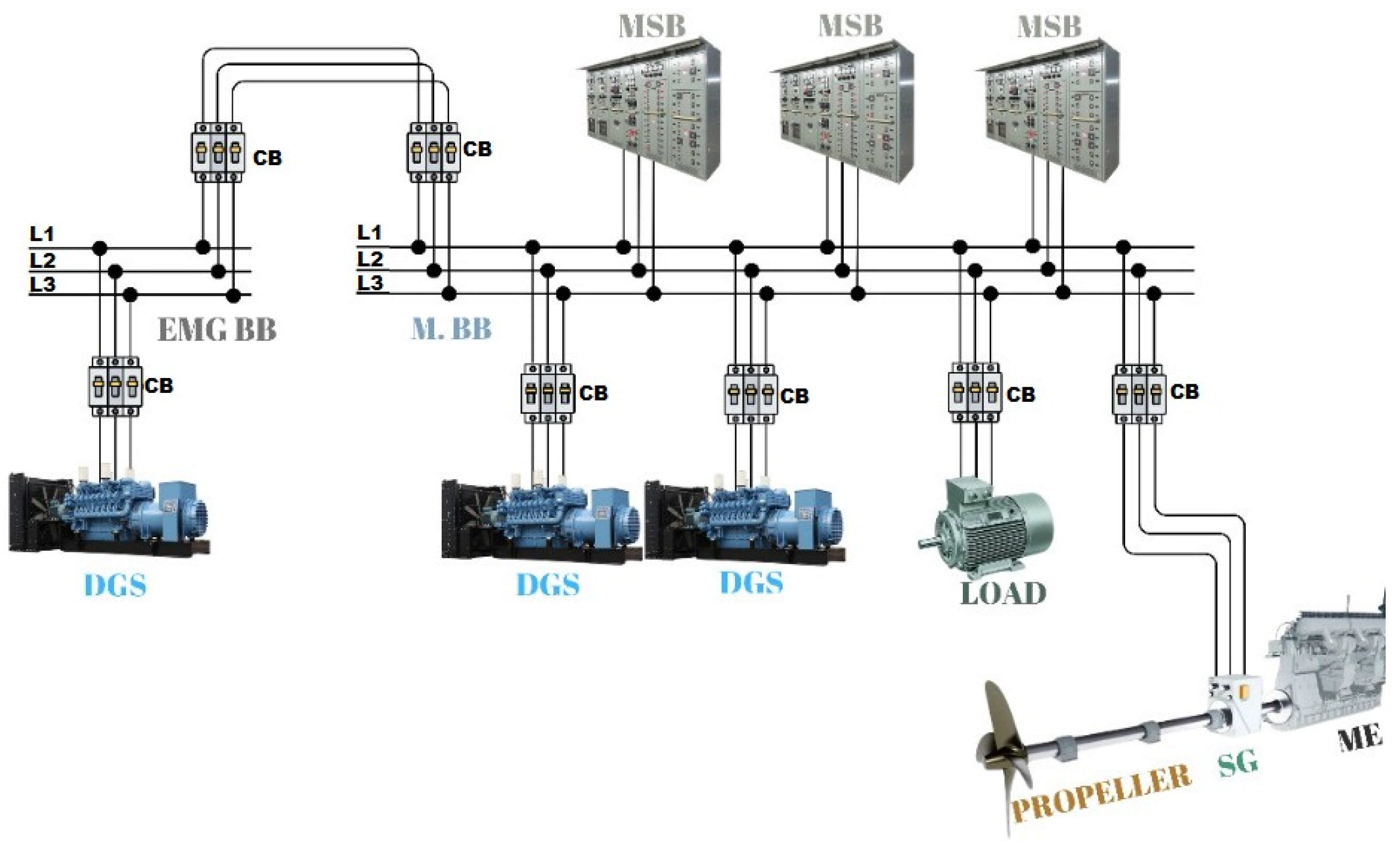
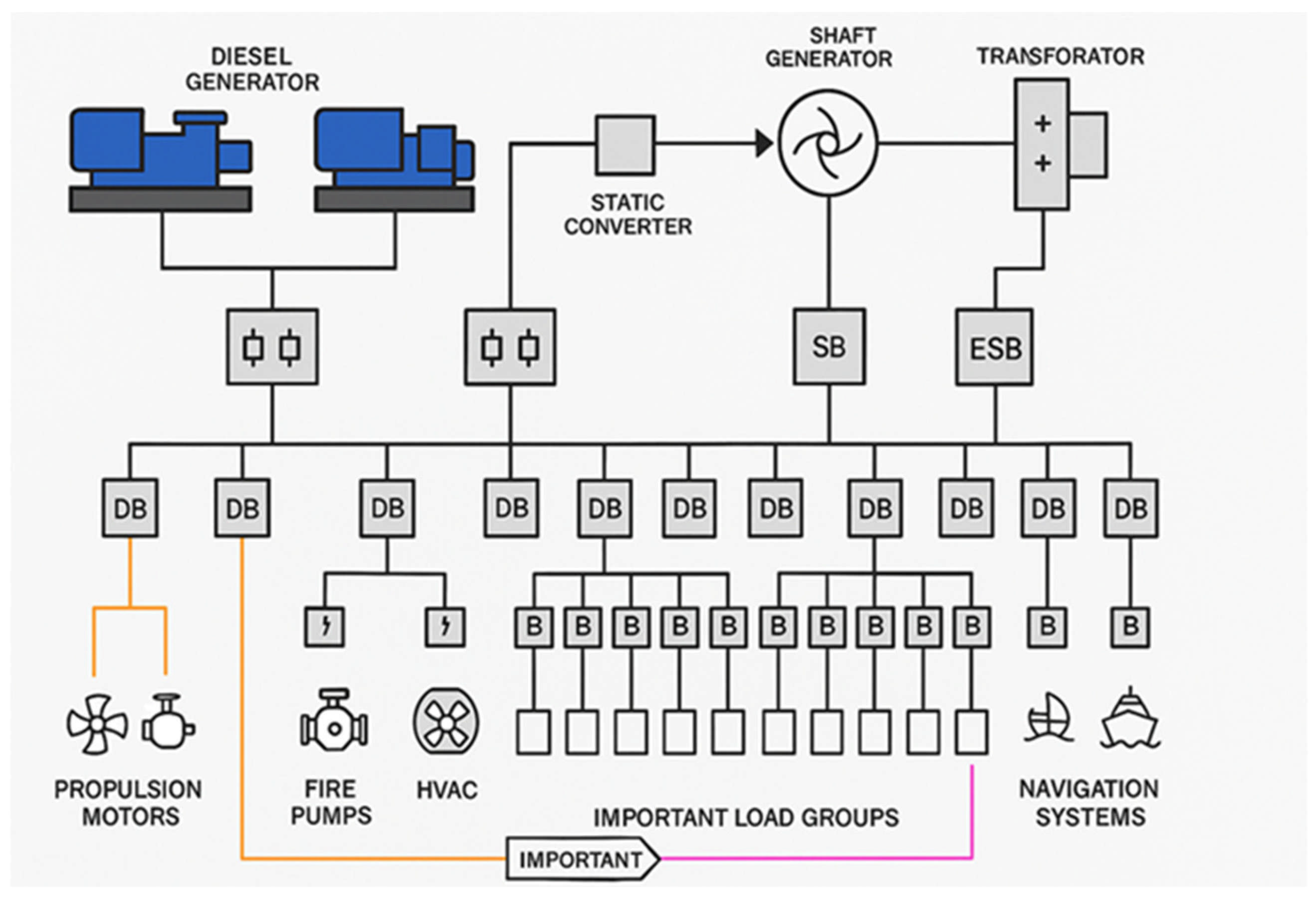
The
Figure 10 schematic diagram illustrates the electrical system configuration of a ship equipped with a shaft generator. This schematic general diagram illustrates the general architecture that is typically employed in ship applications. In such cases, the shaft generator serves as a pivotal component within the shipboard power generation system. The illustration provides a synopsis of the integration of the shaft generator with the main switchboards, converters, diesel generators, propulsion motor, and load distribution units.
The investigative process commences with the analysis of the rotor and stator currents, followed by a comparative evaluation of their amplitudes, ripple levels, and harmonic contents. An exhaustive analysis of the electrical behaviors of both systems is conducted, with particular emphasis on the differences between the response time of the rotor current and the stability of the stator current. The results obtained from this study offer significant insights into the assessment of the systems’ impact on energy efficiency and operational stability, thereby serving as a valuable reference point in the design process.
This analysis focuses on the behaviors of speed and torque, which are of key importance in this study. The responses of both generator systems under various load scenarios are analyzed in detail by means of speed-torque curves obtained through simulations. Comparisons, especially in terms of speed variability and torque stability, clearly reveal the operational advantages and disadvantages of Squirrel Cage and Double Squirrel Cage structures. These analyses provide an in-depth evaluation of the responsive behaviors of the systems to sudden load changes and their performance under constant operating conditions.
4.1. Shaft Generator Type Analysis
As demonstrated in
Figure 11, the torque value of the Double Squirrel Cage shaft generator model decreases over time. The high torque value initially obtained is subject to a gradual decline as the generator accelerates. This observation indicates that this configuration offers a distinct advantage, particularly in applications such as heavy lifting operations and crane systems that necessitate high initial torque. However, in scenarios requiring uninterrupted and consistent speed operation, it is evident that the performance is constrained due to the decline in torque values.
Conversely, the Squirrel Cage SG model exhibits an increase in torque over time, reaching a maximum level. This maximum torque, estimated at approximately 2600 Nm, is attained at approximately 12 s, which is earlier than the 10 s mark for the Double Squirrel Cage model. Despite its initial lower torque output, the model’s ability to steadily increase torque over time makes it an optimal choice for systems that demand sustained and consistent speed.
A thorough analysis of the data presented in
Figure 12 reveals that the torque value remains constant at low speeds, signifying that the generator functions with high efficiency within this speed range. At medium speeds, the decline in torque is more regulated, indicating that the system maintains its operational balance. However, the rapid decrease in torque at high speeds suggests that the operation of the generator at these speeds is not efficient and that the optimal operating speeds should be reduced.
The analysis indicates that double squirrel cage SGs demonstrate optimal performance, particularly in systems necessitating high starting torque. This efficacy is attributed to the generator’s capacity to generate substantial initial torque while sustaining a balanced acceleration. Conversely, the decline in torque with increasing speed signifies that this system is more appropriate for applications requiring low torque and consistent speed. This evaluation underscores the necessity for a judicious selection of the application domains of double squirrel cage shaft generators, in alignment with the prevailing parameters of operation.
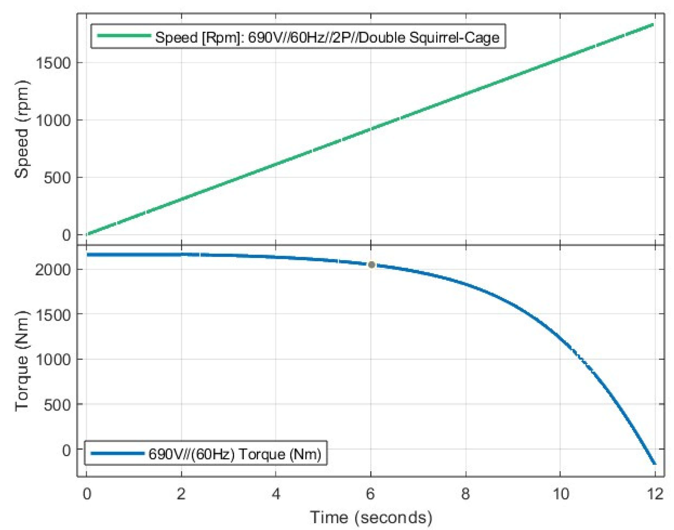
The high initial torque of the SG facilitates an efficient operation of heavy loads, while the steady increase in speed over time demonstrates a balanced and controlled acceleration process. However, the observed decrease in torque as the speed increases indicates that the generator operates with optimal efficiency within a specific speed range. Double Squirrel Cage SGs offer an ideal solution for systems requiring large initial loads due to their high starting torque and stability as the speed increases. The negative correlation between torque and speed indicates that this type of generator is particularly effective in applications with constant speed and low torque requirements. The graphs in
Figure 13 clearly demonstrate the necessity of careful evaluation when selecting SGs suitable for specific application areas.
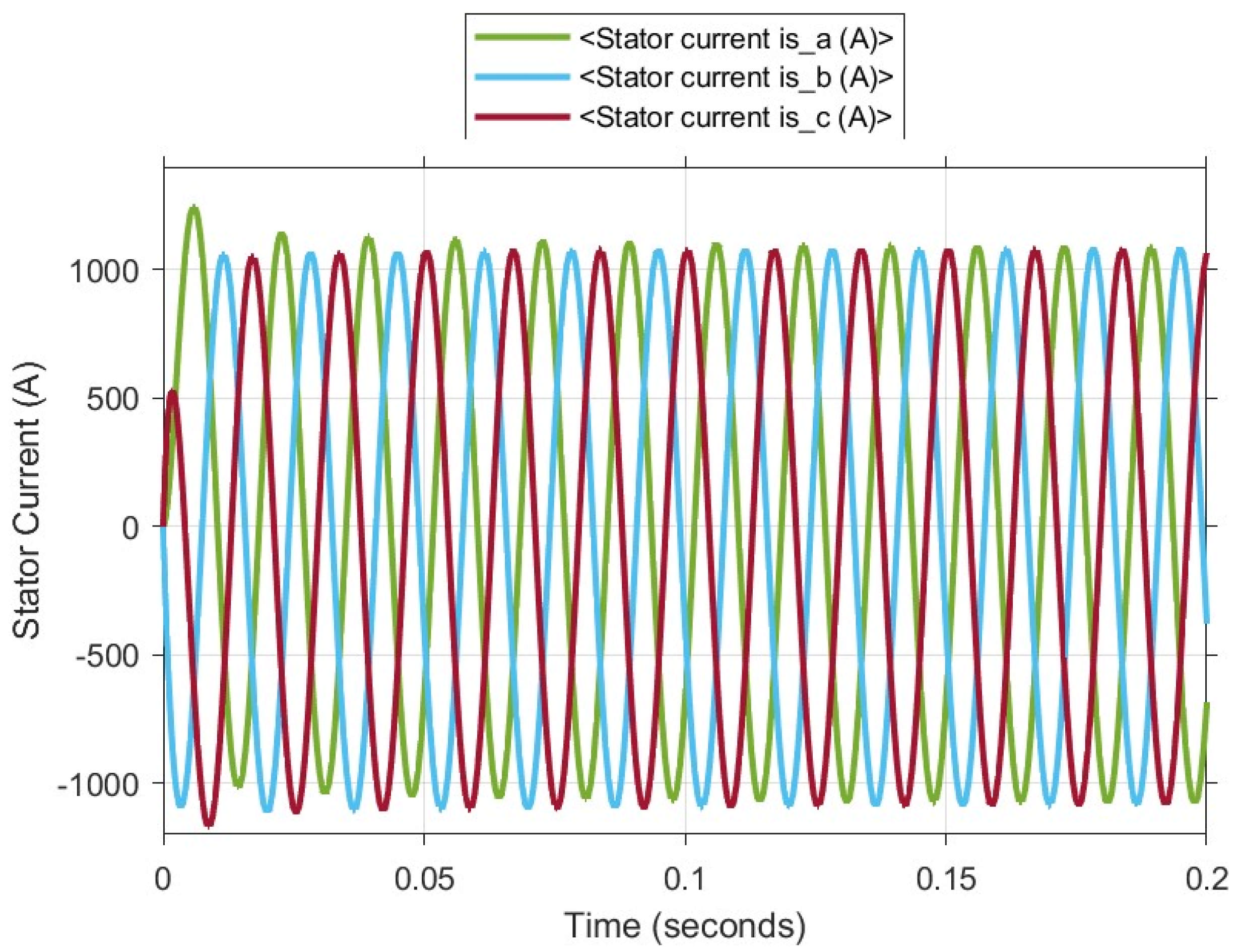
As demonstrated in
Figure 14, the SG displays consistent and balanced performance during operation, with the rotor currents aligning with the theoretically anticipated behaviors of the three-phase system. This validates the model’s precision. The operating voltage of 690 V instigates high-amplitude currents in the rotor windings, leading to the generation of a substantial magnetic field. This, in turn, facilitates the generator’s capacity to produce high torque. The transient regime at start-up is rapidly damped, enabling the system to reach a steady state. The data thus demonstrate that the shaft generator is both design efficient and operationally reliable.
As illustrated in
Figure 15, the SG functions within its nominal parameters, with the loads being connected to the SG in a balanced manner. When a system is connected to the grid, successful synchronization between the SG and the grid is indicated, thereby demonstrating that the SG is operating in a stable mechanical and electrical state. Consequently, the current operating state of the system is reliable, and efficient energy production is ensured.
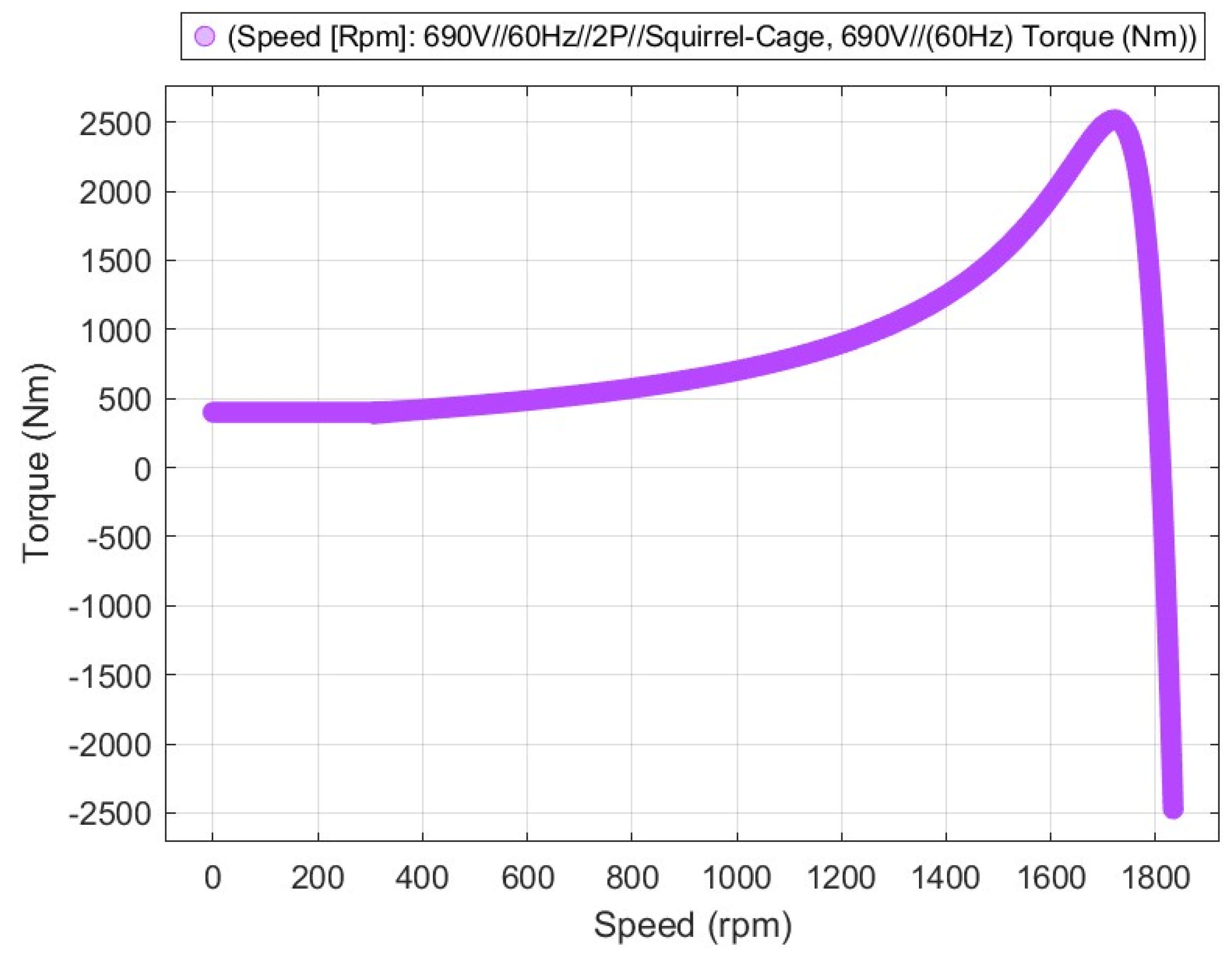
As illustrated in
Figure 16, the maximum torque is attained at a speed of approximately 1800 rpm, signifying that the SG has attained its maximum mechanical load capacity. It is noteworthy that an increase in load can precipitate instability in the system. Beyond this speed, the torque undergoes a rapid decline, which can be attributed to the mechanical stability of the SG. It is evident that by surpassing the synchronous speed of 1800 rpm, the generator experiences a decline in mechanical stability, leading to a reduction in torque production. The shaft generator’s stable operating point is identified at speeds that are marginally below the maximum torque. This speed range corresponds to the operational range of the SG under conditions of rated load.
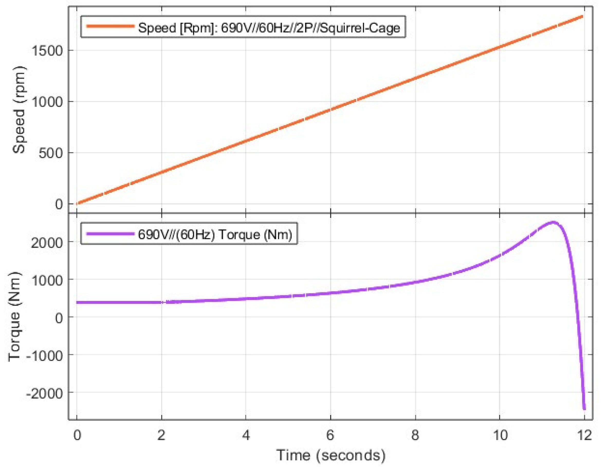
As demonstrated in
Figure 17, the variation of speed (rpm) and torque (Nm) of a 690 V, 60 Hz, 2-pole squirrel cage induction SG with respect to time is illustrated. In the time period of approximately ten seconds, the speed approaches a constant value. This finding suggests that the SG has attained synchronous speed and stabilized in relation to the load torque.
Figure 18 illustrates the time-dependent fluctuation of the currents in the rotor windings (ir_a, ir_b, ir_c) of a 690 V, 60 Hz, 2-pole squirrel-cage asynchronous shaft generator. These currents initially exhibit a rapid increase, eventually attaining a constant value. This phenomenon is known as the starting current effect of the shaft generator. It is evident that in the absence of rotor rotation during the initial start-up phase, the currents within the rotor circuit exhibit elevated values. Over a brief period, these currents attain a constant amplitude and transition into a stable, sinusoidal configuration. The maintenance of the three-phase sinusoidal structure signifies the preservation of symmetry between the phases, thereby indicating the absence of any imbalance.
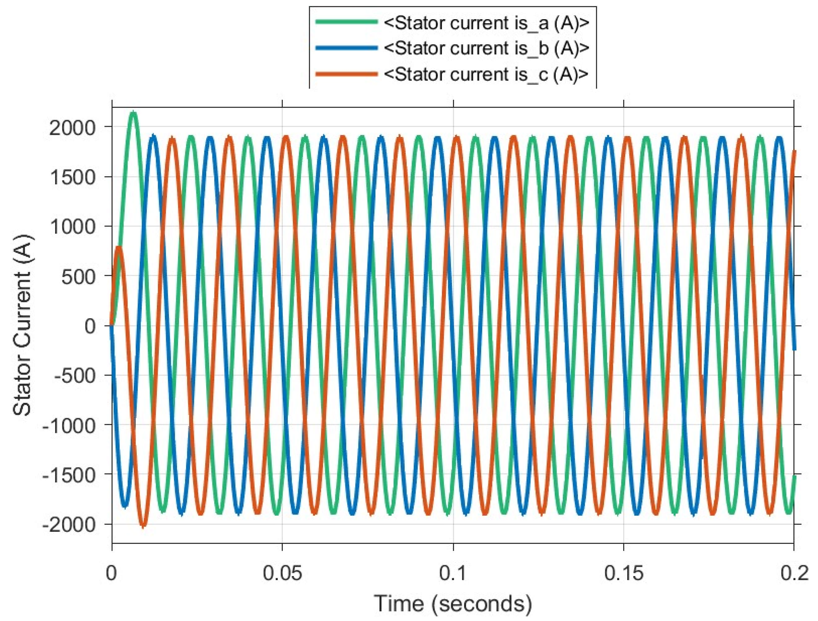
As illustrated in
Figure 19, the stator currents of the shaft generator are generated in a smooth manner, and the generator operates in synchrony with the grid. The absence of any distortion in the current suggests that the SG is operating efficiently. However, the evaluation of high magnitudes of inrush currents may necessitate precise adjustments to the overcurrent protection systems, emphasizing the necessity for caution in this regard.
4.2. Number of Poles Analysis
This study investigates the characteristic behaviors of a squirrel cage SG operating at 690 V voltage and 60 Hz frequency for five different pole values. For this purpose, the torque values of the generator for different configurations of 2, 4, 6, 8, and 12 poles are measured and analyzed. The study investigates the effects of each pole number on the performance of the generator, with a particular focus on torque generation. Furthermore, the analysis encompassed a comprehensive evaluation of the disparities in generator efficiency and torque values across various pole numbers.
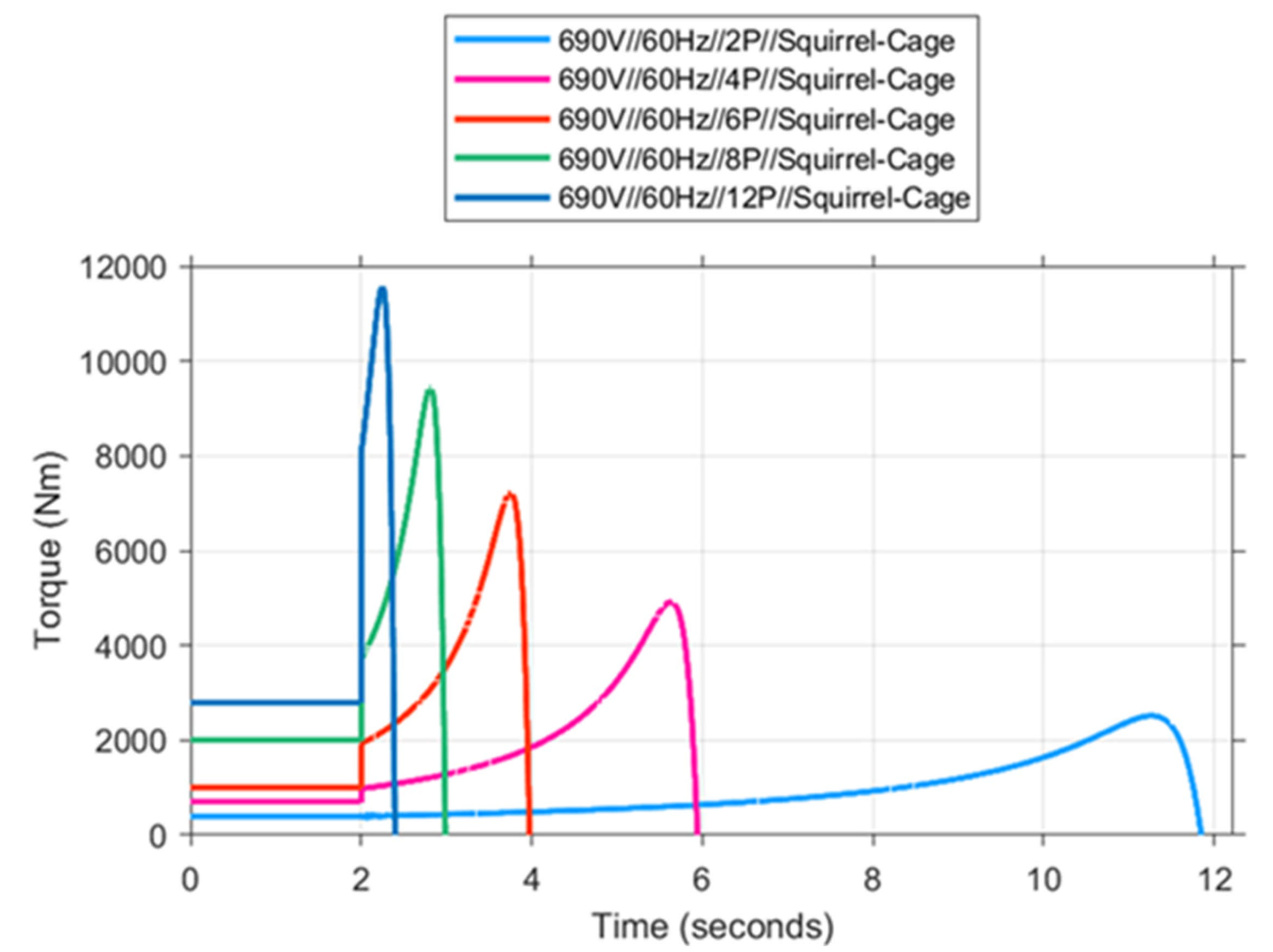
As demonstrated in
Figure 20, increasing the number of poles in a generator can result in alterations to the power generated. Specifically, SGs with a high pole number generally necessitate larger mechanical forces due to their operation at low speeds, which can potentially lead to power losses. Conversely, SGs with a higher pole count tend to exhibit higher torque at low speeds. Additionally, SGs operating at low speeds typically demonstrate reduced efficiency due to increased electrical losses and heat generation.
The high torque capacity of 12-pole SGs is attributable to their capacity to operate at low speeds, a feature that is particularly advantageous in systems operating with heavy loads. Conversely, SGs with a reduced pole count, such as 2-pole generators, are favored in compact and efficient systems that operate at higher speeds.
4.3. Voltage Characteristic Analysis
This research presents a comparative analysis of the effects on the rotor and stator, time-dependent analysis of the torque, and general performance characteristics of 2-pole squirrel-cage SG systems operating at 60 Hz. The analysis is conducted at different voltage levels, including 690 V, 440 V, 400 V, and 380 V, which are commonly utilized in ship applications. The objective of this analysis is to comprehensively evaluate the effects of each voltage level on rotor dynamics and stator voltages.
As demonstrated in
Figure 21, the shaft generator operating at 690 V exhibits the highest torque capacity and the most rapid increase in torque, at which point it attains its maximum torque value. In generators operating at lower voltage levels, torque is limited, and the increase in torque is more gradual. Evidently, an augmentation in voltage gives rise to a proportional escalation in the shaft generator’s torque capacity. This lends weight to the notion that the torque curve serves as a pivotal performance indicator, exhibiting a direct correlation with the applied voltage. At a voltage of 690 V, the SG demonstrates optimal torque output and efficiency. Conversely, a decline in voltage to levels ranging from 380 V to 400 V results in a reduction in efficiency and the observation of torque limitations. This observation suggests that lower voltage levels have a detrimental effect on the efficiency of the SG.
4.4. Poles Characteristic Analysis
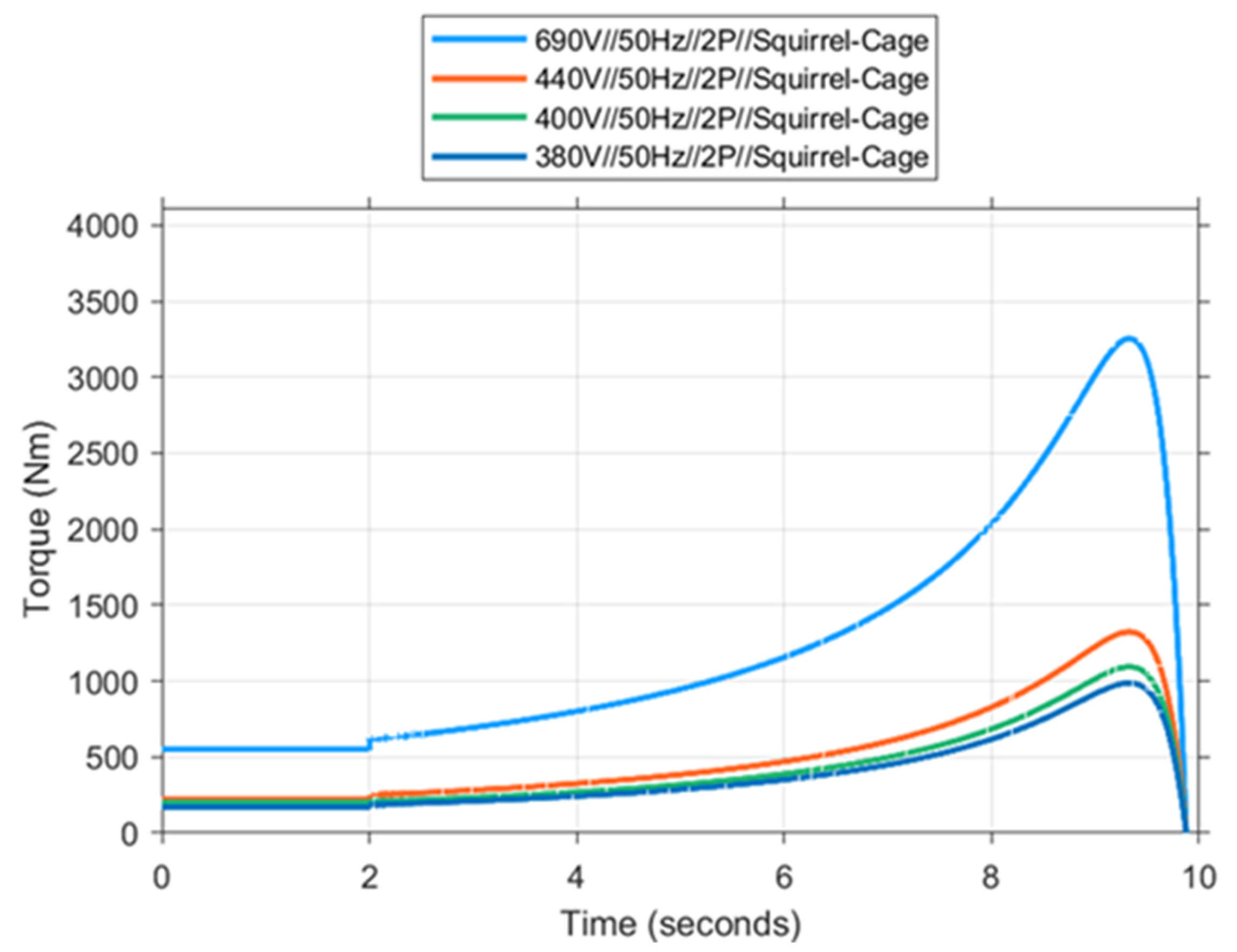
The 2-pole squirrel cage shaft generator system is analyzed in order to ascertain its characteristics at a 50 Hz frequency, with various voltage levels being considered, including 690 V, 440 V, 400 V, and 380 V, which are widely utilized in ship applications.
As demonstrated in
Figure 22, the SG exhibits an increased torque output at higher voltage levels. This indicates that squirrel cage SGs exhibit substantial performance characteristics contingent on the voltage level. The study demonstrates that maximum torque is attained at 690 V, while performance diminishes at reduced voltage levels. It is evident that for a constant initial torque value, higher voltage levels yield significantly higher and more rapid torque development. In summary, it is evident that when higher torque and acceleration performance are requirements, elevated voltage levels, such as 690 V, yield more efficient results.
4.5. Frequency Characteristic Analysis
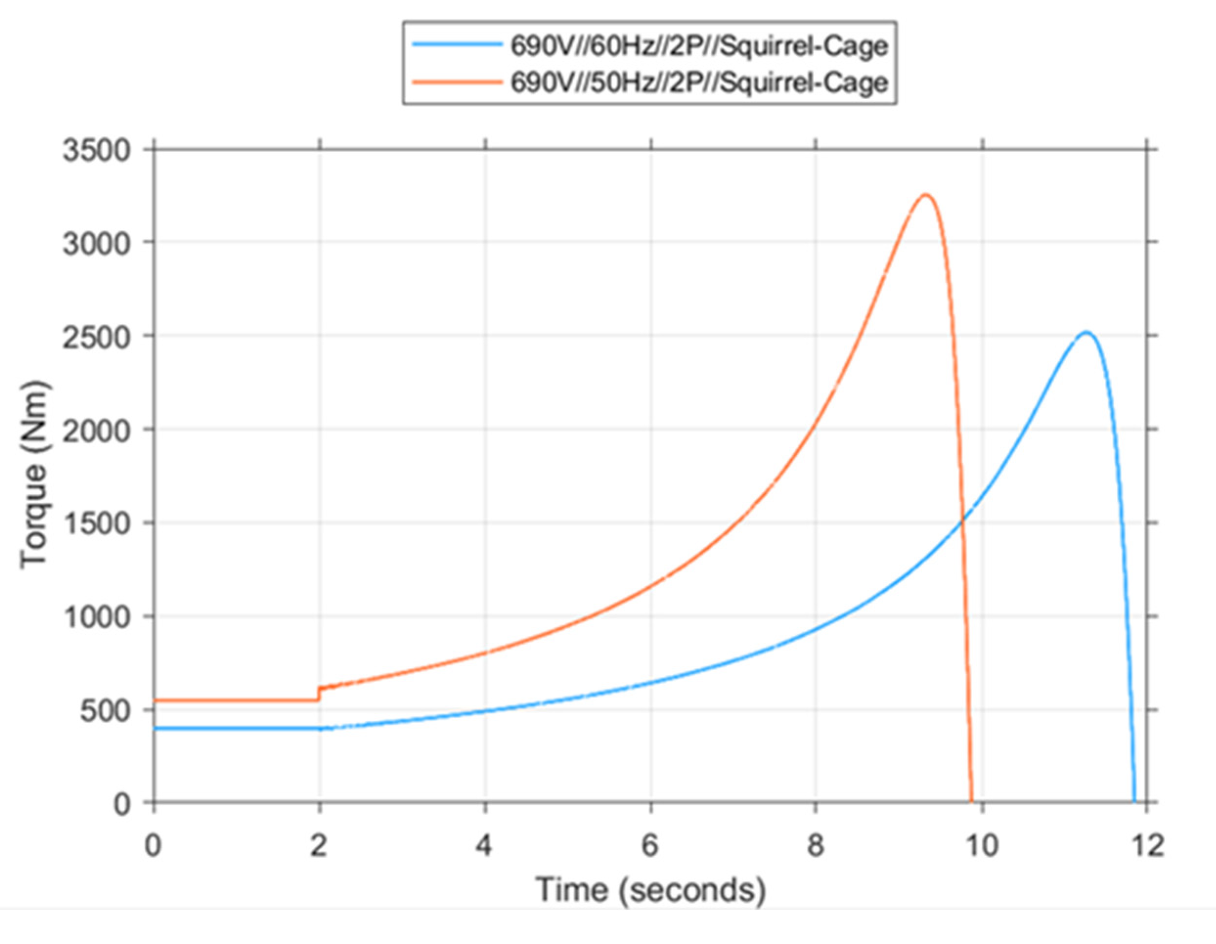
Figure 23 shows the time-dependent variations of torque in a squirrel cage generator operating at 690 V and 60 Hz.
Figure 23 demonstrates that at both frequencies, the initial torques are negligible and almost equal (approximating 500 Nm). A shaft generator functioning at 50 Hz exhibits a significantly more rapid torque curve increase than an SG operating at 60 Hz. This is attributable to the fact that at 50 Hz, the rotor operates at a lower synchronous speed, resulting in a higher slip rate.
As illustrated in
Figure 23, the torque output at 50 Hz is notably higher than that at 60 Hz. In a 690 V 50 Hz shaft generator system, the maximum torque value at 50 Hz is approximately 3252 Nm, while in the same shaft generator system designed for 690 V 60 Hz, this value remains at approximately 2516 Nm. This result indicates that low frequency has a positive effect on the torque generation of the shaft generator. The enhanced torque capacity at 50 Hz facilitates more efficient performance, particularly when dealing with high loads.
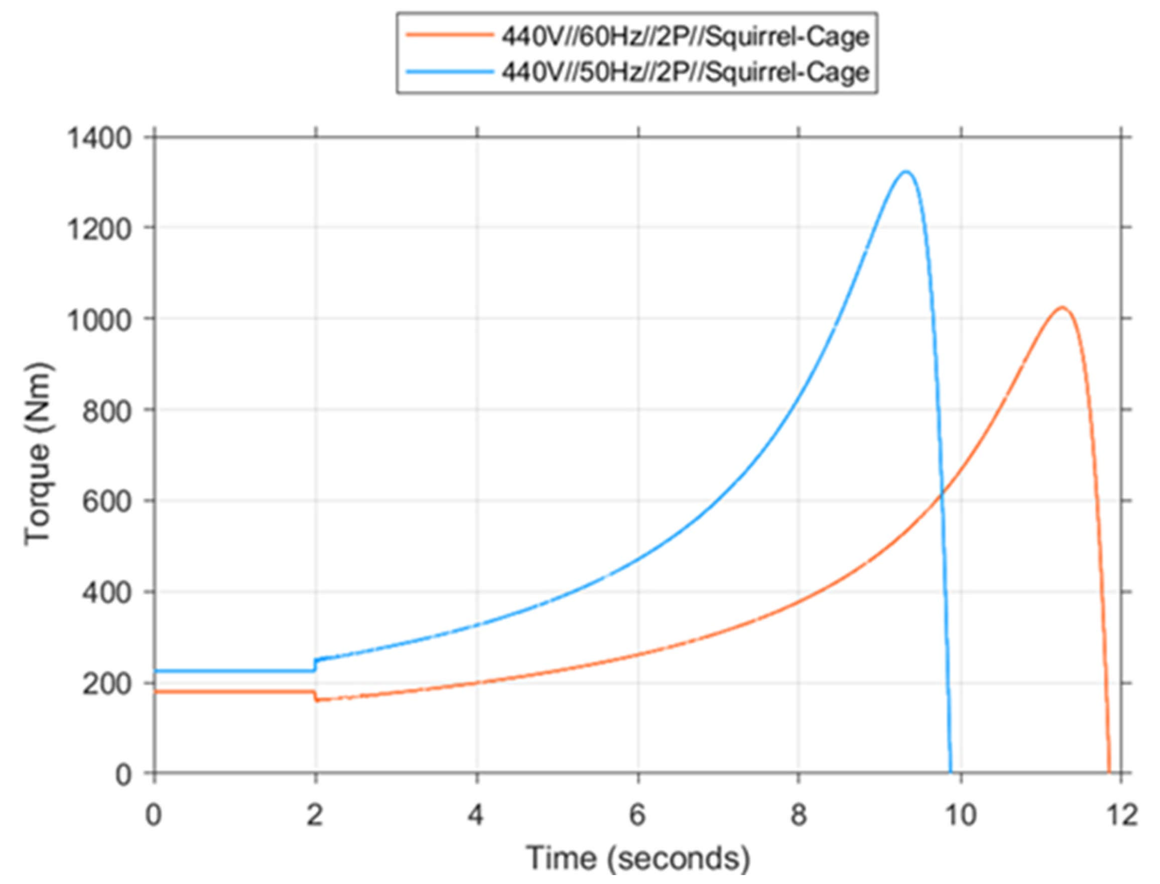
As illustrated in
Figure 24, the torque-time variations of a squirrel cage generator operating at 440 V 50 Hz and 60 Hz show that initial torque values are approximately the same at these frequencies. This finding indicates that the frequency difference has a minor effect on the initial torque of the SGs. The torque curve of the SG operating at 50 Hz demonstrates that it rises more rapidly than at 60 Hz. The phenomenon under investigation can be attributed to the operating conditions of the rotor. Specifically, these conditions consist of a reduced synchronous speed and an elevated slip ratio at 60 Hz in comparison to 50 Hz. This results in an increased magnetic flux, which consequently leads to elevated torque production. The results obtained in the present study demonstrate that decreasing the operating frequency results in an augmentation in the torque capacity of the SG.
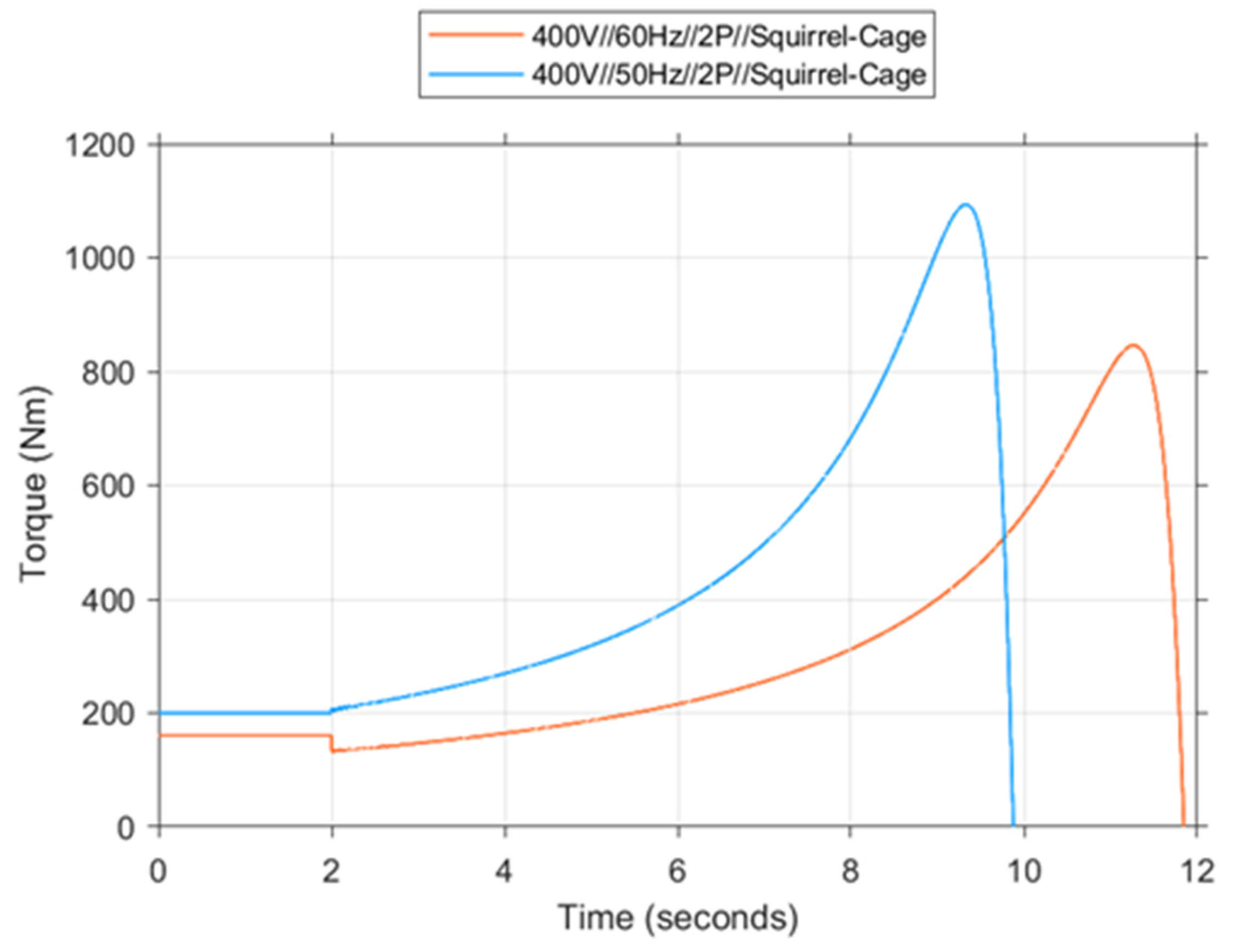
The torque/time plot in
Figure 25 provides significant data for comprehending the response of the SG at 400 V, 50 Hz, and 60 Hz frequencies to frequency-dependent alterations. It is also noteworthy that at a frequency of 50 Hz, after the maximum torque is reached, the torque undergoes a rapid decline. This phenomenon could be indicative of the loss of shaft generator stability under load at a certain point. In contrast, at 60 Hz, the fall after the maximum torque is more gradual and occurs over a longer period of time, as does the rise.
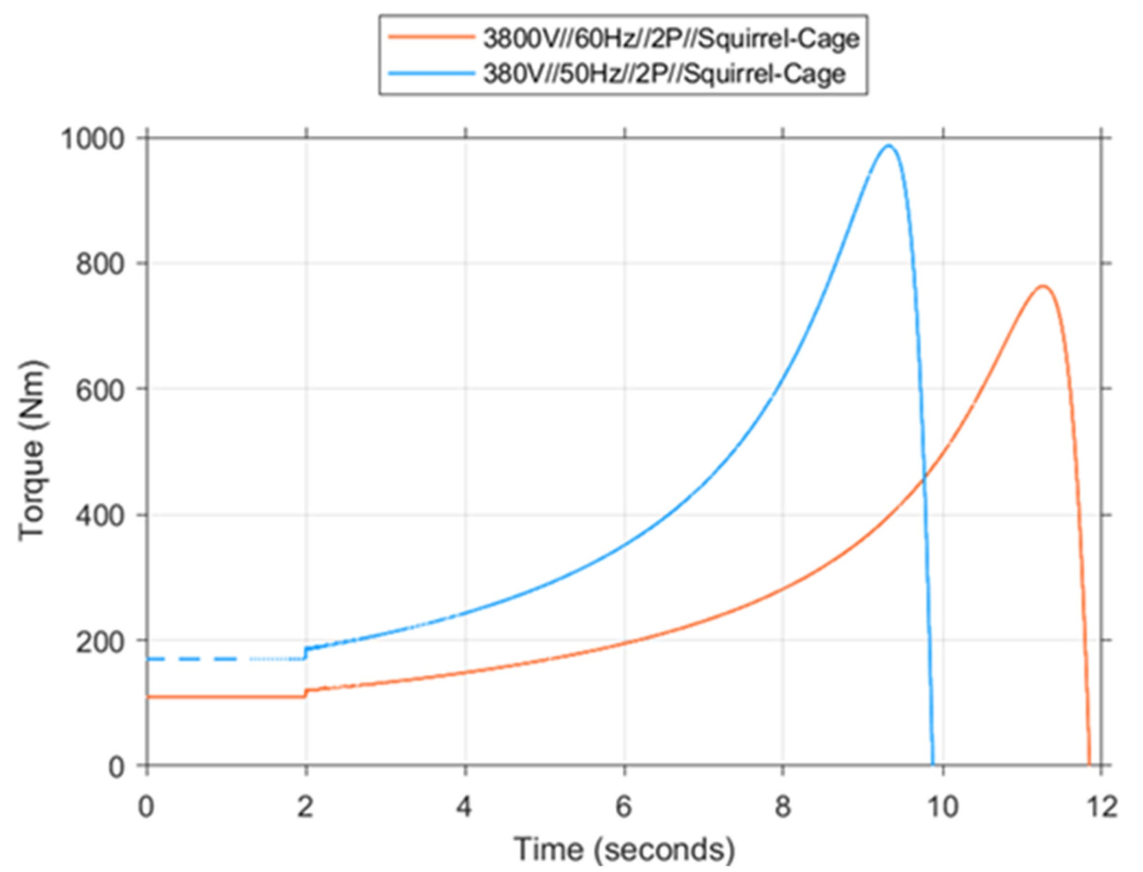
As demonstrated in
Figure 26, an analysis of the torque/time plot was conducted to investigate the response of the SG to frequency variation at low voltage (50 Hz and 60 Hz) at 380 V. The initial torque values at both 50 Hz and 60 Hz frequencies were found to be approximately equal (200 Nm). As demonstrated in
Figure 26, the system demonstrates reduced fluctuations in both rotor speed and output torque when operating below a frequency of 60 Hz. This finding suggests that the system’s dynamic response time is reduced and less susceptible to sudden fluctuations in load.
The utilization of 60 Hz ensures operation in closer proximity to synchronous speed, thereby reducing the slip rate. Consequently, the electromechanical stability of the system is enhanced. Furthermore, the simulation results demonstrate a reduction in harmonic distortion and voltage oscillation for the 60 Hz frequency case.
This analysis demonstrates the variability in SG performance under various low-voltage and different frequency scenarios. It provides guidance on the selection of optimal frequency and voltage values, tailored for specific applications.
A study of the designed shaft generator was undertaken to ascertain the potential for uncertainty.
P: Power (Nm)
T: Torque (W)
ω: Angular speed (rad/s)
According to the uncertainty propagation formula;
Torque (T): 2500 Nm
Rotor Speed (n): 3560 RPM → depending on the angular speed (ω);
Power calculation according to the values found;
Torque Uncertainty calculation according to Equation (11);
Angular speed uncertainty calculation according to Equation (12);
The following uncertainty analysis has been conducted for the designed uncertainty power error calculation in accordance with Equation (13).
The relative uncertainty value is derived from these values;
Table 1 presents the design parameters of the shaft generator that are to be designed, in addition to the characteristic values that were considered in the analysis process. The aforementioned parameters comprise technical components that exert a direct influence on the performance of the system. Such components include, but are not limited to, the following: generator type, connection type (star/delta), rated power, operating voltage, frequency, speed, phase current, maximum torque value, and number of poles. The values given in the table permit both the electromechanical and structural evaluation of the shaft generator. In particular, the torque and speed parameters determine the energy conversion capacity of the generator, while the connection type and number of poles play a decisive role in the electrical behaviors of the machine. The analysis of these parameters reveals how the generator behaves both under design conditions and under different frequency scenarios, thereby providing a technical framework for the load-carrying capacity of the system. The efficiency of the system, which operates with a power factor of 0.86, was increased to 97% from the traditional 95% level commonly observed in similar systems following the implementation of design improvements and the conduct of optimization studies. This enhancement was accomplished by implementing measures to curtail electrical and mechanical losses, culminating in a substantial augmentation in system performance.
5. Conclusions
This paper presents a thorough analysis of rotor shapes, frequencies, and voltages affecting the performance of shaft generators on naval ships. It proposes a method for selecting the most suitable generator, taking into account the specific requirements of the application. The findings of this study will facilitate the optimization of the responsiveness and reliability of industrial applications over time, with simultaneous improvements in energy efficiency.
In this study, the MATLAB/Simulink environment is utilized for the analysis of shaft generators employed on naval ships. This analysis was conducted to furnish a comprehensive evaluation of the electromagnetic performance, operational dynamics, and effectiveness of the generators within the overall system integration. The findings of this study have facilitated the identification of pivotal parameters for enhancing designs and ensuring operational reliability.
A comparative analysis of the speed, torque, and frequency-dependent dynamics of squirrel cage and double squirrel cage rotor types for naval ships was conducted, and their performance in different operational scenarios was compared. The results obtained demonstrate that double squirrel cage structures offer advantages in applications requiring high starting torque, while single squirrel cage structures offer higher efficiency at nominal speed. Furthermore, it has been determined that at a power factor of 0.86, the efficiency of the shaft generator experiences an increase from 95% to 97%. The impact of varying voltage and frequency levels on performance has also been exhaustively investigated. The findings will be useful in selecting suitable shaft generators for engineering applications and system design.
Author Contributions
Conceptualization, K.G.B. and T.D.; methodology, K.G.B.; software, K.G.B.; validation, K.G.B. and T.D.; formal analysis, K.G.B. and T.D.; investigation, K.G.B. and T.D.; resources, T.D.; data curation, K.G.B.; writing—original draft preparation, K.G.B. and T.D.; writing—reviewing and editing, K.G.B. and T.D.; visualization, K.G.B.; supervision, T.D.; project administration, T.D.; funding acquisition, T.D. All authors have read and agreed to the published version of the manuscript.
Funding
This research was supported by the training budget of the Elkon Electric Ship and Electrical Technological R&D Center (Project Number: ARG24-00003) and the Scientific Project Unit of Adana Alparslan Türkeş Science and Technology University (Project Number: 24803001).
Data Availability Statement
The data presented in this study are available at the request of the corresponding author. The data are not publicly available due to the content of confidential information/trade secrets in them.
Conflicts of Interest
Author Kamer Gökbulut Belli was employed by the Elkon Electric. The remaining author declares that the research was conducted in the absence of any commercial or financial relationships that could be construed as a potential conflict of interest.
References
- Wan, C.; Zhao, Y.; Zhang, D.; Yip, T.L. Identifying Important Ports in Maritime Container Shipping Networks along the Maritime Silk Road. Ocean Coast. Manag. 2021, 211, 105738. [Google Scholar] [CrossRef]
- Park, J.S.; Seo, Y.-J.; Ha, M.-H. The Role of Maritime, Land, and Air Transportation in Economic Growth: Panel Evidence from OECD and Non-OECD Countries. Res. Transp. Econ. 2019, 78, 100765. [Google Scholar] [CrossRef]
- Miller, T.; Durlik, I.; Kostecka, E.; Kozlovska, P.; Jakubowski, A.; Łobodzińska, A. Waste Heat Utilization in Marine Energy Systems for Enhanced Efficiency. Energies 2024, 17, 5653. [Google Scholar] [CrossRef]
- Tarnapowicz, D.; German-Galkin, S.; Staude, M. Investigation Concerning the Excitation Loss of Synchronous Generators in a Stand-Alone Ship Power Plant. Energies 2021, 14, 2828. [Google Scholar] [CrossRef]
- Sáez Álvarez, P. From Maritime Salvage to IMO 2020 Strategy: Two Actions to Protect the Environment. Mar. Pollut. Bull. 2021, 170, 112590. [Google Scholar] [CrossRef] [PubMed]
- Bilgili, L. Life Cycle Comparison of Marine Fuels for IMO 2020 Sulphur Cap. Sci. Total Environ. 2021, 774, 145719. [Google Scholar] [CrossRef] [PubMed]
- Psaraftis, H.N.; Zis, T.; Lagouvardou, S. A Comparative Evaluation of Market Based Measures for Shipping Decarbonization. Marit. Transp. Res. 2021, 2, 100019. [Google Scholar] [CrossRef]
- Parnyakov, A.V. Innovation and Design of Cruise Ships. Pac. Sci. Rev. 2014, 16, 280–282. [Google Scholar] [CrossRef]
- Yuksel, O.; Blanco-Davis, E.; Spiteri, A.; Hitchmough, D.; Shagar, V.; Di Piazza, M.C.; Pucci, M.; Tsoulakos, N.; Armin, M.; Wang, J. Optimising the design of a hybrid fuel Cell/Battery and waste heat recovery system for retrofitting ship power generation. Energies 2025, 18, 288. [Google Scholar] [CrossRef]
- Tu, H.; Liu, Z.; Zhang, Y. Study on Cost-Effective Performance of Alternative Fuels and Energy Efficiency Measures for Shipping Decarbonization. J. Mar. Sci. Eng. 2024, 12, 743. [Google Scholar] [CrossRef]
- Maloberti, L.; Zaccone, R. An environmentally sustainable energy management strategy for marine hybrid propulsion. Energy 2025, 316, 134517. [Google Scholar] [CrossRef]
- Hinić, V.; Radica, G.; Jurić, Z.; Lalić, B.; Vidović, T. Performance analysis of hybrid marine energy systems. Transp. Res. Procedia 2025, 83, 178–185. [Google Scholar] [CrossRef]
- Radica, G.; Vidović, T.; Šimunović, J.; Jurić, Z. Overview of hybrid marine energy system configurations and system component modeling approaches. Energies 2025, 18, 1189. [Google Scholar] [CrossRef]
- Nishikata, S.; Odaka, A.; Koishikawa, Y. Steady-State Performance Analysis of Shaft Generator Systems. In Proceedings of the Power Conversion Conference–PCC ’97, Nagaoka, Japan, 3–6 August 1997; Volume 2, pp. 853–858. [Google Scholar] [CrossRef]
- Prousalidis, J.; Hatzilau, I.K.; Michalopoulos, P.; Pavlou, I.; Muthumuni, D. Studying Ship Electric Energy Systems with Shaft Generator. In Proceedings of the IEEE Electric Ship Technologies Symposium, Philadelphia, PA, USA, 25–27 July 2005; pp. 156–162. [Google Scholar] [CrossRef]
- Tatsuta, F.; Tsuji, T.; Emi, N.; Nishikata, S. Studies on a Wind Turbine Generator System Using a Shaft Generator System. In Proceedings of the 2005 International Conference on Electrical Machines and Systems, Nanjing, China, 27–29 September 2005; Volume 2, pp. 931–936. [Google Scholar] [CrossRef]
- Diao, L.; Wang, D.; Peng, Z.; Guo, L.; Wang, H. Sensorless Control of a Stand-Alone Doubly Fed Induction Machine for Ship Shaft Generator Systems. In Proceedings of the Fifth International Conference on Intelligent Control and Information Processing, Dalian, China, 18–20 August 2014; pp. 373–377. [Google Scholar] [CrossRef]
- Peng, L.; Li, Y.; Chai, J.; Yuan, G. Vector Control of a Doubly Fed Induction Generator for Stand-Alone Ship Shaft Generator Systems. In Proceedings of the 2007 International Conference on Electrical Machines and Systems (ICEMS), Seoul, Republic of Korea, 8–11 October 2007; pp. 1033–1036. [Google Scholar] [CrossRef]
- Belli, K.G.; Esenboğa, B.; Yavuzdeğer, A.; Demirdelen, T. Design and Energy Efficiency Analysis of a Shaft Generator for Military Ships. Turk. J. Electr. Power Energy Syst. 2024, 4, 165–180. [Google Scholar] [CrossRef]
- Barros, J.; Diego, R.I. A Review of Measurement and Analysis of Electric Power Quality on Shipboard Power System Networks. Renew. Sustain. Energy Rev. 2016, 62, 665–672. [Google Scholar] [CrossRef]
- ResearchGate. (PDF) Electric Power Quality Problems in Ship Systems: A Classification Method. 2004. Available online: https://www.researchgate.net/publication/237798421_Electric_Power_Quality_problems_in_ship_systems_A_classification_method (accessed on 26 April 2025).
- Anish. The Green Source of Power on Ship–Shaft Generator. Marine Insight. Available online: https://www.marineinsight.com/environment/the-green-source-of-power-shaft-generator/ (accessed on 26 April 2025).
- Mindykowski, J. Power Quality on Ships: Today and Tomorrow’s Challenges. In Proceedings of the 2014 International Conference and Exposition on Electrical and Power Engineering (EPE), Iasi, Romania, 16–18 October 2014; pp. 001–018. [Google Scholar] [CrossRef]
- Nguyen, T.-T.; Nguyen, D.-M.; Ngo, Q.-V. The Power-Sharing System of DFIG-Based Shaft Generator Connected to a Grid of the Ship. IEEE Access 2021, 9, 109785–109792. [Google Scholar] [CrossRef]
- Sarigiannidis, A.G.; Patsios, C.; Pittaras, A.; Kladas, A. Geometry Optimization of Synchronous Machines Used on Ship Shaft Generator Systems. Mater. Sci. Forum 2014, 792, 245–250. [Google Scholar] [CrossRef]
- Schøyen, H.; Sow, H. A Decision-Making Tool Concerning Retrofit of Shaft Generator Frequency Converter. Ocean Eng. 2015, 109, 103–112. [Google Scholar] [CrossRef]
Figure 1.
Model of shaft generator. (a) front view, (b) side view of shaft generator model.
Figure 1.
Model of shaft generator. (a) front view, (b) side view of shaft generator model.
Figure 2.
General diagram of the electrical power system of a three-phase vessel.
Figure 2.
General diagram of the electrical power system of a three-phase vessel.
Figure 3.
The conventional electrical structure is a ship’s electrical energy system structure.
Figure 3.
The conventional electrical structure is a ship’s electrical energy system structure.
Figure 4.
The shaft generator structure is defined as the ship’s electric power system structure.
Figure 4.
The shaft generator structure is defined as the ship’s electric power system structure.
Figure 5.
The ship structure consisting of a shaft generator structure.
Figure 5.
The ship structure consisting of a shaft generator structure.
Figure 6.
Typical shaft generator structure of military vessels. (a) front view, (b) side view of different shaft generators.
Figure 6.
Typical shaft generator structure of military vessels. (a) front view, (b) side view of different shaft generators.
Figure 7.
3D model of the shaft generator structure.
Figure 7.
3D model of the shaft generator structure.
Figure 8.
ANSYS Maxwell design of the shaft generator structure. (a) ANSYS Maxwell design of the shaft generator structure and (b) ANSYS Maxwell cross-sectional view of the shaft generator structure.
Figure 8.
ANSYS Maxwell design of the shaft generator structure. (a) ANSYS Maxwell design of the shaft generator structure and (b) ANSYS Maxwell cross-sectional view of the shaft generator structure.
Figure 9.
MATLAB/Simulink analysis depending on shaft generator, power, and frequency parameters.
Figure 9.
MATLAB/Simulink analysis depending on shaft generator, power, and frequency parameters.
Figure 10.
General diagram of a ship with a Shaft Generator.
Figure 10.
General diagram of a ship with a Shaft Generator.
Figure 11.
Torque Graph of Squirrel Cage (Upper) and Double Squirrel Cage (Lower).
Figure 11.
Torque Graph of Squirrel Cage (Upper) and Double Squirrel Cage (Lower).
Figure 12.
Speed/torque graph of the Double Squirrel Cage model.
Figure 12.
Speed/torque graph of the Double Squirrel Cage model.
Figure 13.
Time-based Graphs of Double Squirrel Cage Motor Speed (Upper) and Torque (Lower).
Figure 13.
Time-based Graphs of Double Squirrel Cage Motor Speed (Upper) and Torque (Lower).
Figure 14.
Rotor current graph of a double squirrel cage system.
Figure 14.
Rotor current graph of a double squirrel cage system.
Figure 15.
Stator current graph of a double squirrel cage system.
Figure 15.
Stator current graph of a double squirrel cage system.
Figure 16.
Squirrel Cage speed/torque graph.
Figure 16.
Squirrel Cage speed/torque graph.
Figure 17.
Time-based Graphs of Squirrel Cage Motor Speed (Upper) and Torque (Lower).
Figure 17.
Time-based Graphs of Squirrel Cage Motor Speed (Upper) and Torque (Lower).
Figure 18.
Squirrel Cage rotor current graph.
Figure 18.
Squirrel Cage rotor current graph.
Figure 19.
Squirrel Cage stator current graph.
Figure 19.
Squirrel Cage stator current graph.
Figure 20.
Torque/time graph according to the number of poles.
Figure 20.
Torque/time graph according to the number of poles.
Figure 21.
Torque/time graph for voltage characteristics.
Figure 21.
Torque/time graph for voltage characteristics.
Figure 22.
Poles Characteristic Analysis.
Figure 22.
Poles Characteristic Analysis.
Figure 23.
690 V torque/time graph for 50 Hz and 60 Hz frequency values.
Figure 23.
690 V torque/time graph for 50 Hz and 60 Hz frequency values.
Figure 24.
Torque/time graph for 440 V 50 Hz and 60 Hz frequency values.
Figure 24.
Torque/time graph for 440 V 50 Hz and 60 Hz frequency values.
Figure 25.
Torque/time graph at 400 V, 50 Hz, and 60 Hz frequency.
Figure 25.
Torque/time graph at 400 V, 50 Hz, and 60 Hz frequency.
Figure 26.
Torque/time graph at 380 V, 50 Hz, and 60 Hz frequency.
Figure 26.
Torque/time graph at 380 V, 50 Hz, and 60 Hz frequency.
Table 1.
Design and analysis parameters of the shaft generator model.
Table 1.
Design and analysis parameters of the shaft generator model.
| Parameters | Design Values | Analysis Values |
|---|
| Generator Type | Squirrel Cage | Squirrel Cage |
| Connection Type | Star | Delta |
| Rated Power | 1500 kW | 800 kW |
| Rated Voltage | 690 V | 690 V |
| Frequency | 50 Hz | 60 Hz |
| Speed | 1036 rpm | 3560 rpm |
| Current | 1572 | 780 A |
| Torque | 14,292 Nm | 2500 Nm |
| Poles | 6p | 2p |
| Protected by enclosure | IP 55 | IP 55 |
| Power Factor | 0.86 | 0.86 |
| Efficiency | %95 | %97 |
| Disclaimer/Publisher’s Note: The statements, opinions and data contained in all publications are solely those of the individual author(s) and contributor(s) and not of MDPI and/or the editor(s). MDPI and/or the editor(s) disclaim responsibility for any injury to people or property resulting from any ideas, methods, instructions or products referred to in the content. |
© 2025 by the authors. Licensee MDPI, Basel, Switzerland. This article is an open access article distributed under the terms and conditions of the Creative Commons Attribution (CC BY) license (https://creativecommons.org/licenses/by/4.0/).


