Article

Influences of the Stiffness and Damping Parameters on the Torsional Vibrations’ Severity in Petroleum Drilling Systems

by
Mohamed Zinelabidine Doghmane
Bob L. Herd Department of Petroleum Engineering, Texas Tech University, Lubbock, TX 79401, USA
Energies 2025, 18(14), 3701; https://doi.org/10.3390/en18143701
Submission received: 20 June 2025 / Revised: 5 July 2025 / Accepted: 9 July 2025 / Published: 14 July 2025
(This article belongs to the Section H: Geo-Energy)

Abstract

The torsional, lateral, and axial vibrations that occur during drilling operations have negative effects on the drilling equipment. These negative effects can cause huge economic impacts, as the failure of drilling tools results in wasted materials, non-productive time, and substantial expenses for equipment repairs. Many researchers have tried to reduce these vibrations and have tested several models in their studies. In most of these models, the drill string used in oil wells behaves like a rotating torsion pendulum (mass spring), represented by different discs. The top drive (with the rotary table) and the BHA (with the drill pipes) have been considered together as a linear spring with constant torsional stiffness and torsional damping coefficients. In this article, three models with different degrees of freedom are considered, with the aim of analyzing the effect of variations in the stiffness and damping coefficients on the severity of torsional vibrations. A comparative study has been conducted between the three models for dynamic responses to parametric variation effects. To ensure the relevance of the considered models, the field data of torsional vibrations while drilling were used to support the modeling assumption and the designed simulation scenarios. The main novelty of this work is its rigorous comparative analysis of how the stiffness and damping coefficients influence the severity of torsional vibrations based on field measurements, which has a direct application in operational energy efficiency and equipment reliability. The results demonstrated that the variation of the damping coefficient does not significantly affect the severity of the torsional vibrations. However, it is highly recommended to consider all existing frictions in the tool string to obtain a reliable torsional vibration model that can reproduce the physical phenomenon of stick–slip. Furthermore, this study contributes to the improvement of operational energy efficiency and equipment reliability in fossil energy extraction processes.

1. Introduction

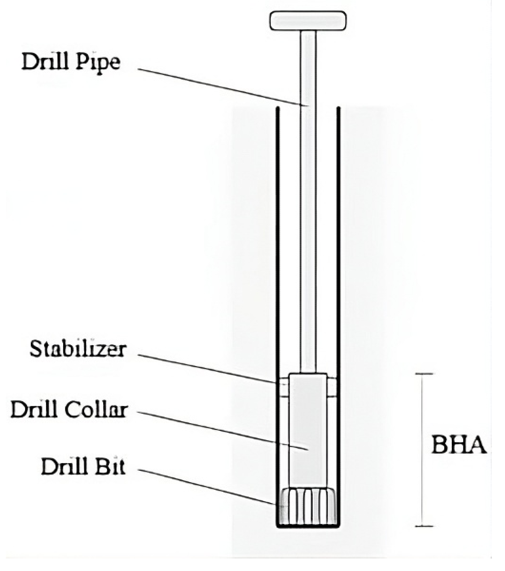
Torsional vibrations can have detrimental effects on drilling performance; to minimize these vibrations, many models have been proposed in the literature, wherein the thin drill pipes are characterized by a slender structure, represented by discs with constant stiffness. The bottom hole assembly (BHA) is composed of more thick-walled tubes, which are heavier than normal pipes and have a negligible stiffness coefficient. Whereas the most common models for capturing uncoupled torsional vibrations consist of several parallel discs rotating around their common axis, drill pipes are characterized by the stiffness coefficient K, and drill collars have a damping coefficient C. However, the number of discs varies from one study to another; for example, there are those that consist of a model with n degrees of freedom in [1], four degrees of freedom in [2], and three degrees of freedom in [3]. Nevertheless, the effects on torsional vibration severity of choosing one of these models and fixing its parameters have not been considered, and the influences of stiffness and damping coefficients have not been discussed before. Modeling the rotary drilling system is a compromise: greater freedoms offer greater precision at the cost of computational complexity, which may potentially lead to control system divergence. Therefore, in this research, a two-degree-of-freedom model required dynamic representation, computational efficiency, and interpretability was proposed to investigate stiffness and damping influences.
An understanding of torsional vibration is not only essential for protecting down-hole equipment but also crucial for making the entire drilling process more energy efficient. Uncontrolled stick–slip converts a large proportion of the mechanical energy provided by the top drive into heat loss, raises fuel consumption, and requires undesirable well control operations that maximize non-productive time. Through the quantitative determination of the way stiffness and damping variations govern the initiation and amplitude of these vibrations, the present research directly contributes to enhancing operating energy efficiency and equipment reliability in fossil–energy production chains. To connect numerical analysis to real working conditions, we incorporated measurement-while-drilling (MWD) data from an Algerian vertical well. Two downhole sensor packages, placed above the bit and at the top of the BHA, recorded torque, RPM, weight-on-bit, standpipe pressure, and tri-axial vibration levels continuously. These measurements were utilized (i) to calibrate the damping and stiffness parameters that define the three models and (ii) to compare simulated stick–slip response with field-measured torsional oscillations. Integrating these field observations into the simulation scenarios ensures that the parametric-variation study simulates realistic drilling conditions, which makes the conclusions more relevant in practice.
Drill string vibration analysis has progressed significantly from simple analyses of coupled axial, lateral, and torsional vibration stability by Ahmadi & Altintas, 2013 in [4] and early control methods for torsional oscillations by Ullah et al., 2016 in [5]. The need for more targeted mitigation was identified by later studies, which introduced drilling dynamics models developed specifically for high-frequency torsional oscillation (HFTO) mitigation as introduced by Shen et al., 2020 in [6] and investigated the influence of parametric variations and rock-bit contact on stick–slip vibrations by Mendil et al., 2021a, 2021b in [7,8]. These outcomes were used as the basis of other studies, and control techniques evolved further to include torsional vibration damping through hybrid sliding PID controllers as introduced by Mendil et al., 2021c in [2]. Moreover, machine-learning approaches, such as support vector machines, were applied for a stick–slip severity evaluation as discussed by Caballero et al., 2021 in [9]. More recently, Landar et al., 2024a in [10] developed and tested a Smart 4 controller embedded in the drill string for real-time vibration load measurement during drilling; this controller allowed the real-time control of drilling parameters by operators to avoid equipment failure.
Regarding hardware solutions, Shatskyi et al., 2023 in [11] proposed a shell shock absorber with dry friction and synthesized a structural hysteresis model for predicting its behavior under cyclic nonmonotonic loading, which demonstrated its potential for enhanced damping in drilling applications. Furthermore, Landar et al., 2024b in [12] proposed a novel shock absorber design with a torque-responsive screw mechanism with analytical and numerical models to increase vibration damping and tool protection at heavy loads. Their work was based on Velichkovich, 2007 in [13], who focused on the design optimization of shell springs as elastic elements in drilling dampers.
The horizon further expanded to the application of stochastic analyses of coupled vibrations developed by Volpi et al., 2021 in [14] and full theoretical–numerical analyses of nonlinear coupled axial–torsional dynamics given by Li et al., 2021 in [15]. Subsequent research in 2022 further applied machine learning to torsional and lateral vibration severity through the research of Alsaihati & Alotaibi, 2022 in [16], investigated comprehensive axial–torsional–lateral dynamics under wellbore conditions through the research of Fang et al., 2022 in [17], and provided experimental validation of the effects of torsional vibration on penetration rate through the research of Barnett et al., 2022 in [18]. Zhang et al., 2023 in [19] integrated a review of the HFTO knowledge and led to the current research on integrating vibration data to optimize drilling with advanced decision matrices as described by Barboza et al., 2025 in [20]. This article is dedicated to studying the influence of these parameter variations on the two-degree-of-freedom model. This paper contributes to the field by offering a targeted comparative analysis of how stiffness and damping affect the severity of torsional vibrations. Its findings, supported by MWD field data, directly enhance drilling operations’ energy efficiency and equipment reliability. To study the influence of the stiffness coefficient K and the damping coefficient C, three sets of values have been selected based on field data and compared for the same model. For the first model set, there is a difference between the two discs’ stiffness coefficient K [5,7]. For the second set, there are differences between the two coefficients, namely the stiffness K and the damping coefficient C [8,21]. For the third model set, it has been assumed that there is only a difference in the damping coefficient C. The open-loop simulation scenarios were conducted in a MATLAB R2025a environment, and the obtained results demonstrated the influence of variations in the stiffness and damping coefficients on the system response. Based on these simulation results, it was demonstrated that, unlike variations in the stiffness coefficient, variations in the damping coefficient do not have a significant effect on the appearance and severity of torsional vibrations [9,16,22].
The rest of the manuscript is organized as follows: Section two is dedicated to describing the drill string components to facilitate understanding of the conceptual part of the study. Section three is then dedicated to field observations and the measurement of torsional vibrations. Section four is dedicated to the development of the mathematical model and the methodology proposed to identify the dynamic of the system with different degrees of freedom. Then, section five introduces the simulation results of drill string dynamics in various scenarios of parametric variations that mimic field conditions. This manuscript concludes with final remarks and recommendations for future research.

2. Drill String

The drill string, which descends into the subsurface, consists of two main parts: the upper part is composed of pipes, and the lower part represents the bottom hole assembly (BHA), as shown in Figure 1.

2.1. The Drill Pipes

The pipes are steel tubes approximately nine meters in length and with an outside diameter of five inches. They are connected by tapered threaded joints (tool-joint) [23]. Their role is to allow the transmission of rotation from the rotating table to the drilling tool, and they also permit the vertical circulation of the drilling fluid between the top and the bottom of the well [14].

2.2. The Stabilizers

Stabilizers are tubes of much shorter length than the drill collars; their outer diameter is close to that of the tool [17]. They are placed at the level of the drill collars to ensure the centering and guidance of the downhole assembly, in addition to keeping and controlling the tool trajectory.

2.3. The Drill Collars

Drill collars are tubes with large sections approximately nine meters in length and an outside diameter ranging from four to ten inches, with an inside diameter of two to three inches [17,22]. They are generally used to apply extra weight to the drilling tool (weight on bit).

2.4. The Drilling Tool

The drilling tool is a destructive element for rocks, in addition to being the source of extracting the material (gas, oil). Different types of bits have been developed in the industry, where each type is used for different field conditions. The most commonly used tool in the Algerian petroleum industry is the PDC (polycrystalline diamond compact). Figure 2 shows the equivalent system used to model the drill string system, including the drilling tool, with simplified dynamics.

3. Petroleum Field Measurement of Torsional Vibrations

To develop a reliable mathematical model and obtain accurate simulation results, MWD data was employed from an oil well where torsional vibrations were recorded. The data was collected at two critical locations along the drill string: one just above the drill bit and the other at the top of the BHA. 
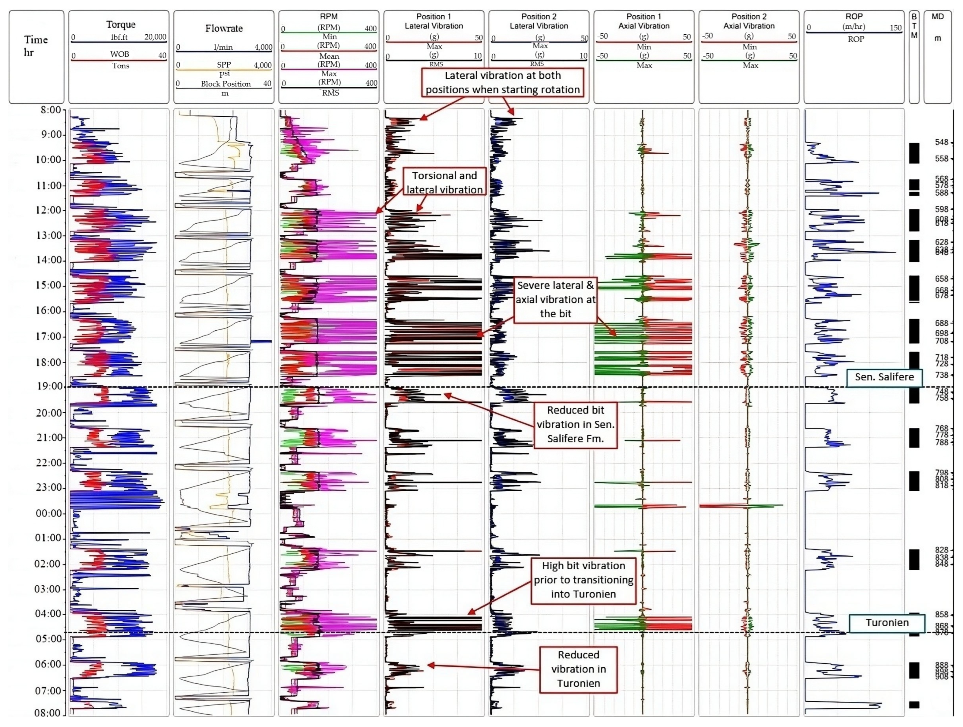
Figure 3 illustrates the various drilling parameters logged during the operation. From left to right, the tracks include the following: time (in hours); torque (in lbf·ft) and weight on bit (WOB, in tons); flow rate (in liters per minute), standpipe pressure (SPP, in psi), and block position (in meters); rotational speed (RPM), including minimum, mean, maximum, and root mean square values; lateral vibrations at position 1 (maximum and RMS in g); lateral vibrations at position 2 (maximum and RMS in g); axial vibrations at position 1 (minimum and maximum in g); axial vibrations at position 2 (minimum and maximum in g); rate of penetration (ROP, in meters per hour); and measured depth (MD, in meters). These measurements provide a comprehensive dataset for analyzing drilling dynamics and calibrating the proposed torsional vibration models. The analysis of this data indicated that the drill string is exposed to coupled torsional and lateral vibrations. However, amplitudes of lateral vibration during the development of torsional are found to be smaller compared to those when lateral vibrations occur independently. Therefore, the present study concentrates on modeling torsional dynamics based on this field data.
As can be seen from Figure 3, drill string has complex vibratory motion. For instance, between around 8:00 and 10:00 (MD ~540–550 m), the initial rotation phase has heavy lateral vibration at Position 1 and Position 2. Between drilling from around 10:00 and 18:00 (MD ~550–680 m), there is both torsional and lateral vibration with a phase of heavy lateral and axial vibration close to the bit, particularly between 16:00–18:00. Most notably, a reduction in bit vibration is observed when drilling into the Sen. Salifere Formation, approximately between 18:00 and 20:00 (MD ~740–750 m). Then, between 03:00 and 05:00 (MD ~840–860 m), the bit’s high vibration is recorded shortly before penetrating into the Turonien Formation, where a clear reduction in vibration is observed at approximately 05:00. An analysis of these data indicated that the drill string is under coupled torsional and lateral vibrations. However, amplitudes of lateral vibration in the process of torsional development are smaller than in those cases when lateral vibrations occur independently. Therefore, the present research focuses on the modeling of torsional dynamics.
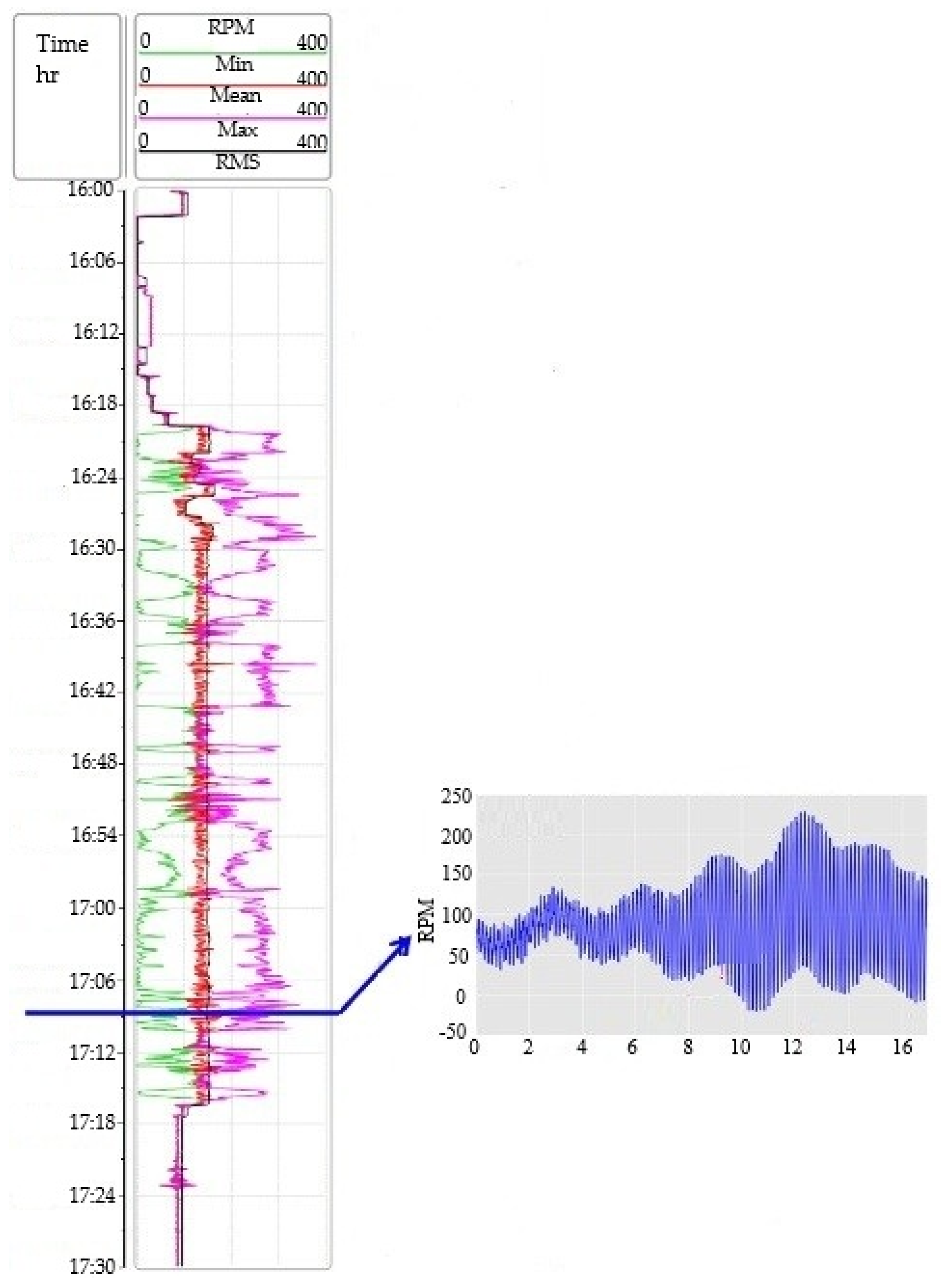
To further examine torsional behavior, a second set of data were measured in the same well one day later, as shown in Figure 4. The figure illustrates time, torque, WOB, RPM (minimum, mean, maximum, and RMS), and ROP. A closer look at the RPM reading by the sensor near the bit reveals clear variations over time, corresponding to high-frequency torsional fluctuations. These fluctuations decrease drilling efficiency through reduced ROP and increased non-productive time.
From Figure 4, the negative RPM measurement of the drill bit indicates the severe torsional vibrations. While normally the angular velocity of the drill bit would be continuously positive and consistent (clockwise), the presence of high-frequency torsional vibration levels causes definite sticking and slipping intervals. During the slip regime, energy stored during the stick regime is released, generating lateral vibrations. These side-to-side oscillations are indicated by the shocks that can produce a momentary reversal of the drill bit’s direction of rotation, which is what these negative RPM readings reflect.
To properly control and reduce such vibrations, mathematical models that represent high-frequency torsional dynamics must first be validated for accuracy. The next section, therefore, introduces the mathematical model proposed to examine the influence of stiffness and damping coefficient in torsional behavior encountered in the field.

4. Mathematical Model

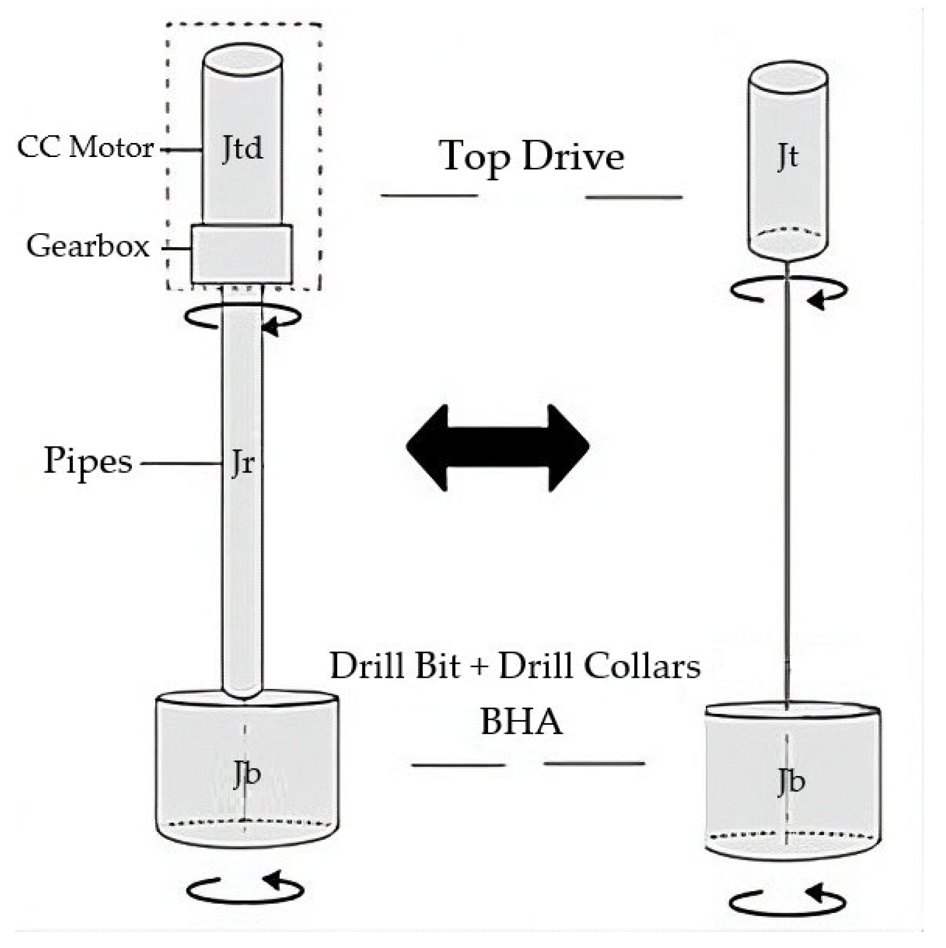
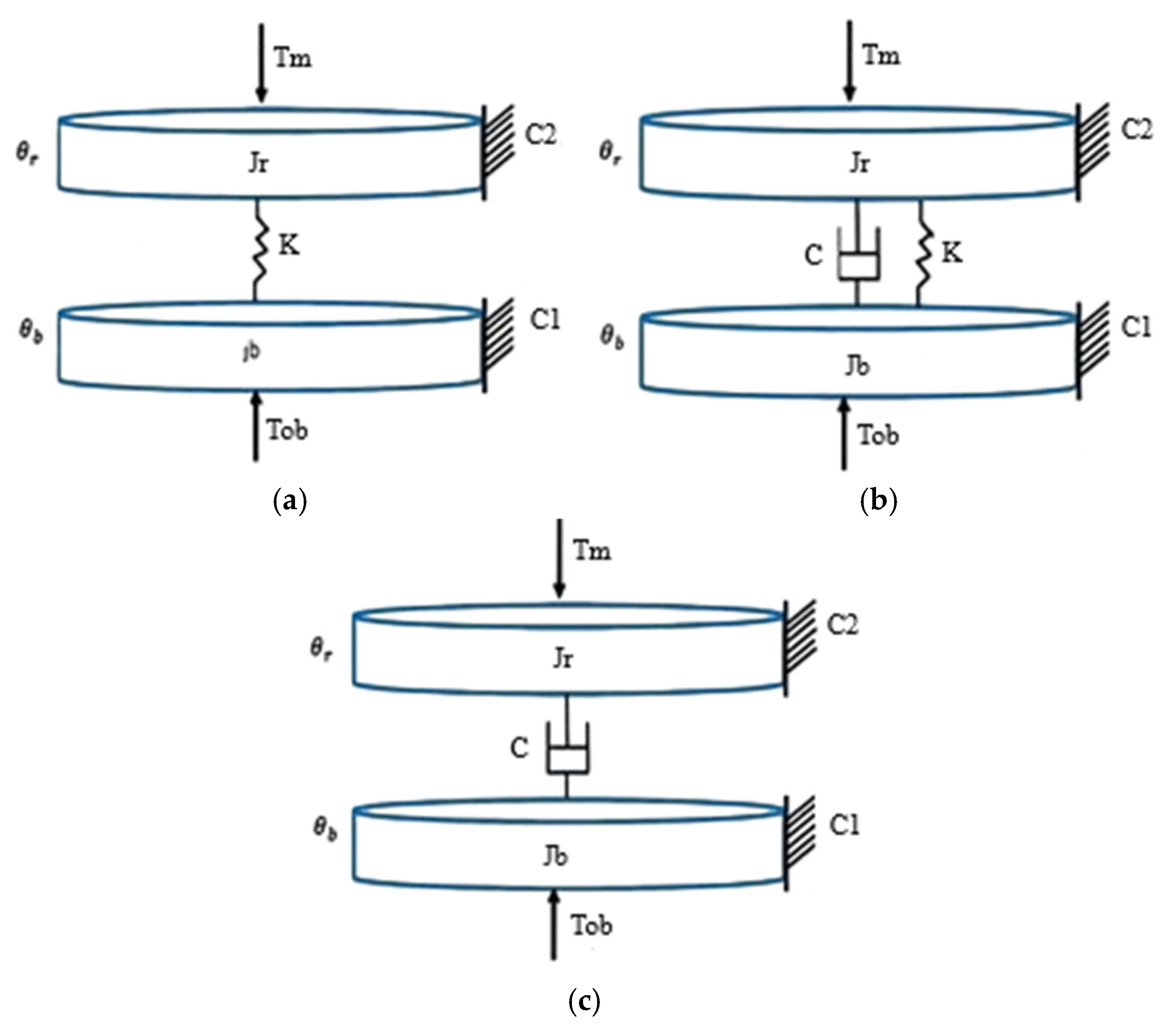
We consider our model in this article to have two degrees of freedom (Figure 5a), which is represented by two discs: the top drive (rotary table) and the BHA (drill bit with drill collar). The drill pipe is represented as a linear spring with a torsional stiffness coefficient K and a torsional damping coefficient C [6]. Figure 5a–c illustrate the torsional model, composed of two discs; the first represents the top drive, and the second is the BHA with the drill bit. J b is the moment of inertia equivalent to drill collars with the drill bit, J r represents the top drive inertia, C 1 is the equivalent viscous damping coefficient of BHA, and C 2 is the viscous damping coefficient at the rotary table. T o b is a nonlinear function of the torque on bit, and T m is the torque supplied by the motor to the system [24,25]. The models have the same parameters except that the stiffness coefficient K is different from zero in Figure 5a. In Figure 5b, both C and K are different from zero, while for Figure 5c, only the damping coefficient C is nonzero. The numerical values used in the simulation are summarized in Table 1.
In this article, we have determined the equation of the motion of the models in Figure 5a–c by applying Lagrange’s equations, which are applied to external energies as given by Equations (1) and (2).
d d t d L d q ˙ i d L d q i = F i ,
L = E c E P ,
where Ec is the total kinetic energy of the system with n degrees of freedom, Ep is the total potential energy of deformation, q is the vector of generalized displacements ( θ r , θ b ), and F is the vector of generalized forces. The Lagrange equations written in kinetic and potential energy and damping functions are given by Equation (3).
d d t d E c d q ˙ i + d D d q ˙ i + d E p d q i = F i ,
Since in this study we present a model with two degrees of freedom (n = 2), the total kinetic and potential energies, as well as the total damping and generalized forces, are given by Equations (4), (5), (6), and (7), respectively.
E c = 1 2 j r θ ˙ r 2 + 1 2 j b θ ˙ b 2 ,  
E P = 1 2 K θ r θ b 2 ,
D = 1 2 C θ ˙ r θ ˙ b 2
F = C 2 θ ˙ r C 1 θ ˙ b T o b ( θ ˙ b ) T m ( θ ˙ r )
While dissipation losses occur along the drill string, they are most frequent at direct contacts between the drill string and the borehole. Such contacts are random but most frequently occur at the drill pipe connections, as these are the weakest links in the drill string. Equation (6) is the mathematical representation of the total damping between the drill bit and the top drive. We have taken for granted that all dissipation damping in all contacts between the drill bit and top drive is cumulative and, therefore, can be summed and considered only as total dissipation damping. This is true for real drilling systems but can be completely wrong if each contact point would generate local stick–slip vibrations with a significant effect on other points in the drill string.
The equation of motion for part 1 (top drive) is found by deriving Equation (3) with respect to θ r , as given by Equation (8).
d d t d E c d θ ˙ r + d D d θ ˙ r + d E p d θ r = F i ( θ 1 ) ,
The equation of the motion of part 2 (BHA) is found by deriving Equation (3) with respect to θ b , as given by Equation (9).
d d t d E c d θ ˙ b + d D d θ ˙ b + d E p d θ b = F i ( θ b ) ,  

4.1. The First Model

The equations of the motion of the first model set are shown in Equation (10).
θ ¨ r = 1 j r k θ r θ b C 2 θ ˙ r T m θ ¨ b = 1 j b k θ r θ b C 1 θ ˙ b T o b ,
By inserting the variables’ changes given by Equations (11) and (12) into Equation (10), Equation (13) is obtained.
θ ˙ b = x 1 ,   ( θ r θ b ) = x 2 ,   θ ˙ r = x 3 ,
T m = u + C 2 ϕ r e f ,   a 1 = C 1 j b ,   b 1 = K j b ,   c 1 = 1 j b ,   a 2 = C 2 j r ,   b 2 = K j r ,   c 2 = 1 j r ,   d 1 = c j b ,   d 2 = c j r
x ˙ 1 = a 1 x 1 + b 1 x 2 + c 1 T o b x ˙ 2 = x 3 x 1 , x ˙ 3 = a 2 x 3 b 2 x 2 + a 2 φ r e f + C 2 U

4.2. The Second Model

The equations of the motion of the second model set are given by Equation (14).
θ ¨ r = 1 j r k ( θ r θ b ) c ( θ ˙ r θ ˙ b ) C 2 θ ˙ r T m θ ¨ b = 1 j b k ( θ r θ b ) + c ( θ ˙ r θ ˙ b ) C 1 θ ˙ b T o b ,
By inserting the changes of variable given by Equations (11) and (12) into Equations (14) and (15) is obtained.
x ˙ 1 = a 1 x 1 + b 1 x 2 + c 1 T o b + d 1 x 2 x ˙ 2 = x 3 x 1 x ˙ 3 = a 2 x 3 b 2 x 2 + a 2 φ r e f + C 2 U d 2 x 2 ,

4.3. The Third Model

The equations of the motion of the third model set are given by Equation (16).
θ ¨ r = 1 j r c ( θ ˙ r θ ˙ b ) C 2 θ ˙ r T m θ ¨ b = 1 j b c ( θ ˙ r θ ˙ b ) C 1 θ ˙ b T o b ,  
By inserting the variables’ changes given by Equations (11) and (12) into Equations (17) and (18) is obtained. T o b represents the nonlinear relationship between tool and rock [22]. In this article, the same Karnoop model for these three models is used [26,27], and it is given by Equation (19).
T o b = T c + T e              i f     x 1 < D v      a n d      T e < T S T S   S i g n T e      i f      x 1 < D v      a n d      T e > T S T d    S i g n x 1     i f      x 1 D v                        ,  
with
T c = 1 2 R b i t 2 Ɛ   d T d = 1 2 N b μ d R b i t   T s = 1 2 N b μ s R b i t   ,  
We have three different models’ sets; this implies that we have three equations of the external torque T e as described by Equation (19).
T e = c 1 x 1 + K x 2 ;         F i r s t   m o d e l   s e t T e = c 1 x 1 + K x 2 + c x 2 ;      S e c o n d   m o d e l   s e t T e = c 1 x 1 + c x 2 ;          T h i r d   m o d e l   s e t
where d is the depth of cut, ε is the intrinsic specific energy, R b i t is the bit radius, μ d is the dynamic dry frictional coefficient, μ s is the static dry frictional coefficient, W o b is the weight-on-bit, N b = g × W o b ; g = 9.8066; D v = 10 3 ; T e is the applied external torque that must overcome the static friction torques T s to make the bit move; T d is the dynamic friction torque; and D v is zero velocity [28,29].
The parameters on the transitions in Equation (19) were defined with great caution to the point where any inherent discontinuities are less than our sampling interval of 10−6 s in our simulation. This choice helps to avoid mostly the numerical instability issue within the model. Also, the accuracy provided by this model has turned out to be entirely sufficient for constructing conclusions regarding the influence of the stiffness and damping coefficients on the severity of torsional vibration, the central topic of the current study. While a more advanced, smoothed model can yield slight theoretical advantages, the computational expense of such a model would not add much towards enhancing the findings gained for the scope of this particular study.
A key decision in this model development was the choice of a two-degree-of-freedom (2DOF) model for representing the drilling system. While the real drill string is a continuous system with infinite degrees of freedom, a simplified 2DOF model, comprising the top drive and BHA as lumped masses, provides a sufficient representation for capturing the fundamental torsional dynamics, particularly the stick–slip phenomenon. This simplification significantly reduces the computational complexity compared to higher DOF, which makes simulations more efficient and results easier to interpret physically. Although it may not capture all the intricate responses of a real drilling system, such as localized high-frequency vibrations along the drill pipe or complex interactions with the wellbore, it effectively highlights the dominant influences of key parameters like stiffness and damping on overall torsional vibration severity, which is the primary focus of this study. The balance between capturing essential physics and maintaining tractability is crucial for drawing clear and actionable conclusions, especially when calibrating simulation results with field data.

5. Simulation Results

5.1. The First Model Set

In the first model set, only the coefficient of rigidity K has been considered. We observe from Figure 6a that the stick–slip phenomenon is not apparent when using a weight of 150 kN on the bit, as the stick phase does not occur. However, after increasing the weight on the bit, we notice from Figure 6b that the stick–slip phenomenon is well-revealed, such that the bit speed is canceled during a time of 2 s (stick phase). It is increased to a maximum value of about 12 s (slip phase); the maximum speed of the top drive is about 10 (rad/s) for 5 s; and then it decreases to 1 (rad/s) and stabilizes at that speed.

5.2. The Second Model Set

In the second model set, both the stiffness coefficient K and the damping coefficient C were considered. We obtained the same remarks as those of the first model set from Figure 7a. When using the second model set, we noted that the stick phase is not visible and that the values of the top drive and tool speed remain the same; it is stabilized at 30 s with a slight oscillation of the speed of the drill bit, which indicates that the slip phase did not appear [19]. Conversely, when we increase the weight on the bit to 250 kN, we notice in Figure 7b that there is a slight difference compared to the first model set, where the stick phase appears many times compared to the first model set, with a maximum value of the bit speed at approximately 14 (rad/s). This dramatic resemblance is a conclusion that the damping coefficient has little impact on the system responses for these conditions. The conclusion that additional BHA weight reduces torsional vibration severity is largely drawn from simulations based on some parameters and field data from an Algerian petroleum well. In comparison with Figure 7a, which also shows the angular speeds of the top drive and drill bit for the second set of models (where both damping C and stiffness K are taken into account), it can be observed here that the responses of both models at 150 kN WOB are practically the same. The reason why the damping coefficient C effect is minimal can be understood by a comparison of Figure 7b (Model 2 with Wob = 250 kN) and Figure 6b (Model 1 with Wob = 250 kN). Even though Model 2 possesses a damping coefficient C while Model 1 does not, the stick–slip responses are nearly identical in terms of the number of stick–slip periods (close to 5) and maximum bit velocities (around 11 to 14 rad/s). From these results, it can be concluded that the damping coefficient C has a negligible effect on the system’s response. While this finding is valuable information, it must also be understood that there are limitations in its direct application to any drilling scenario. This analysis was conducted using a two-degree-of-freedom model of torsion under certain geological and drilling conditions.

5.3. The Third Model Set

In the third model set, there is only the coefficient of damping C. Based on Figure 8, we can say that we have demonstrated through this model set that the coefficient of damping C has negligible influence on the torsional vibrations because we noticed from Figure 8a that the torsional vibrations are not apparent. Because the stick–slip phase is not shown, the response of the system stabilizes in 30 s with very little fluctuation in the speed of the drill bit. Conversely, when we increase the weight on the bit to 250 kN, we notice in Figure 8b that the maximum value of the top drive speed is about 25 (rad/s); then, it decreases to 1.7 (rad/s) and stabilizes at 60 s [4]. Moreover, the speed of the bit is zero ‘stick phase’ for a 50 s period; after this interval, it increases to 1.7 rad/s and stabilizes at this speed [30].
We concluded that torsional vibrations did not appear during the variation of the damping coefficient alone; however, this does not mean that this coefficient does not influence the system’s response and the severity of the stick–slip phenomenon. Therefore, we conducted a parametric variations effects scenario as detailed in the next subsection.

5.4. Parametric Variation Effect

5.4.1. Viscosity of Drilling Mud

In Figure 9a, the plot illustrates the oscillatory behavior of the tool speed, exhibiting overshoot and static differences, followed by stabilization at t = 20 s. Conversely, in Figure 9b, after an increase in viscosity from 0.07 mPa·s to 0.35 mPa·s, it is observed that the stick-slip phenomenon is mitigated, leading to improved system performance. The system achieves stabilization within 10 s. However, it is worth noting that the practical process of altering mud parameters is time-consuming and may pose risks, such as pressure variations and mud filtrate invasion, that can potentially damage hydrocarbon reservoirs [31,32].

5.4.2. Drill Pipe Length

In Figure 10a, it can be observed that when the total length of the drill rods ( L p ) is set to 1800 m, both the tool velocity and the top drive exhibit minimal oscillation and static difference. However, in Figure 10b, after increasing the total length of the drill string to 3600 m, the tool velocity displays oscillatory behavior with reduced static difference [33]. This indicates that deeper wells are more susceptible to torsional vibrations compared to shallower wells; this is due to the increase of rock density and hardness [20].

5.4.3. Drill Pipe Diameters

The drill pipe outer radius ( R r ) and the drill pipe inner radius ( r r ) were adjusted based on the specific drill pipe types and the diameter of the drilled phase. For R r = 0.1270/2 m and r r = 0.1086/2 m, the results are presented in Figure 11b. Additionally, for R r = 0.1120/2 m and r r = 0.1086/2 m (16-inch phase), the results are shown in Figure 11a. By analyzing this figure, it can be observed that vibrations occur in the 16-inch phase, albeit not as severe, with some overshoot present [30]. However, in phases wider than 12.25 inches, Figure 11b demonstrates a notable increase in the tool’s rotational speed, accompanied by severe vibrations and pronounced oscillations.

5.4.4. BHA Length

Figure 12a illustrates the impact of the BHA length ( L b ) on the tool and top drive speed. In the case where L b is set to 100 m, both the tool and top drive exhibit severe high-frequency oscillations and a noticeable static difference. However, upon increasing the BHA length to 300 m, as shown in Figure 12b, the oscillation of the tool decreases, and the static difference also diminishes compared to the first case. This indicates that the system’s performance is influenced by the length of the BHA, and it can be inferred that the stick–slip phenomenon is affected by the thickness of the BHA collars rather than their length. In other words, any dimension that adds more weight to the tool will ultimately reduce the severity of torsional vibrations [16].
We conducted other simulations by varying the outer radius ( R b ) and inner radius ( r b ) of the drill collar. Specifically, for R b = 0.2159/2 and rb = 0.0564/2, the results are presented in Figure 13. Figure 13a,b demonstrate the impact of increasing the external radius of the BHA on the system’s response. It is observed that this modification influences the behavior of the system, leading to the stabilization of the tool and top drive speeds at around 30 s, with minimal oscillations. On the contrary, reducing the internal radius of the drill collar has negligible effects on the system’s response [18]. Therefore, the primary influence of the BHA lies in its weight. Increasing the weight of the BHA contributes to a decrease in the severity of torsional vibrations, while reducing its weight has the opposite effect. This dramatic resemblance indicates that damping coefficient has little impact on the system responses under these field conditions. The idea that additional BHA weight reduces torsional vibration severity is a known practice in the petroleum drilling engineering, but it has been verified using from simulations based on field data of an Algerian petroleum well. While this finding is valuable information, it must also be understood that there are limitations in its direct application to any drilling scenario.
This analysis was conducted using a two-degree-of-freedom model of torsion and certain geological and drilling conditions. Therefore, to directly extend these results into considerably different geology conditions (e.g., hard rock mining, geothermal drilling in highly fractured rocks, or drilling in ultra-long deepwater wells) with significant heave compensation would demand further study. These conditions have different rock-bit interaction models, borehole configurations, fluid flow, and coupled vibration modes (axial, lateral, and torsional) that cannot be adequately dealt with by the current simplified model. Further research could extend this work using more complex multi-physics models by exploring more diverse rock mechanical properties and contrasting results with field evidence from different geological basins to establish the broader applicability of such results.

6. Conclusions

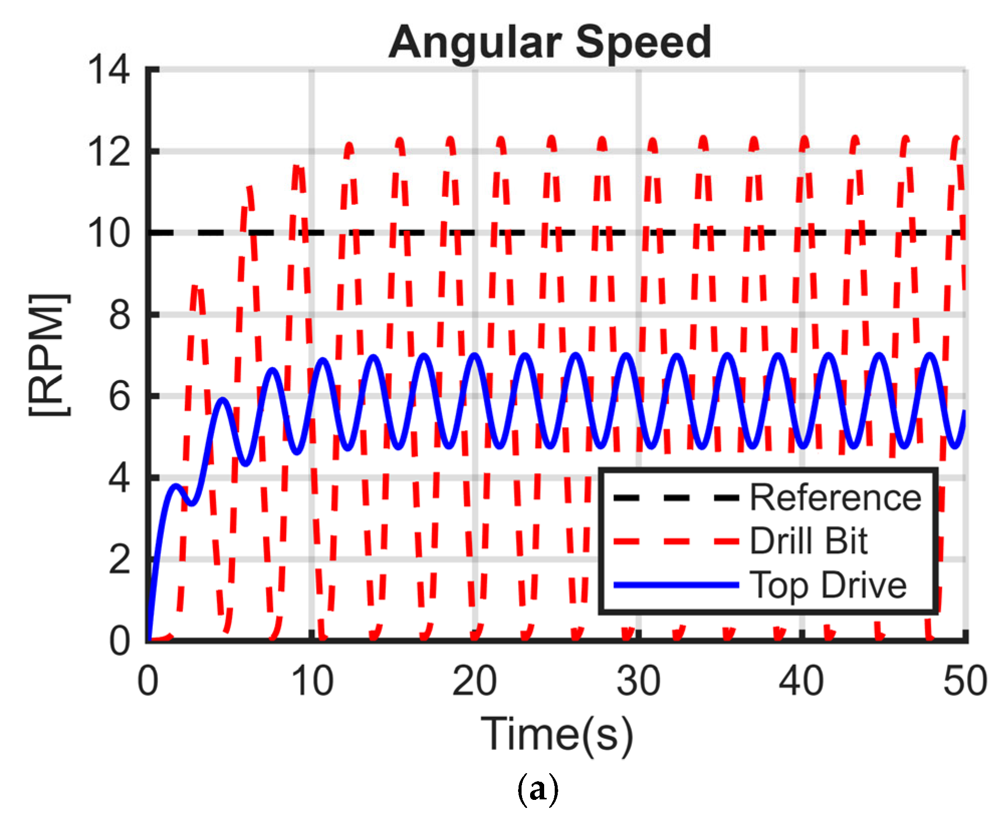
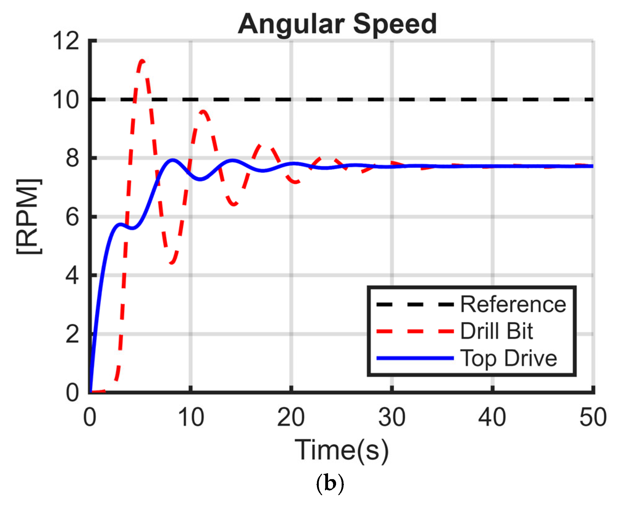
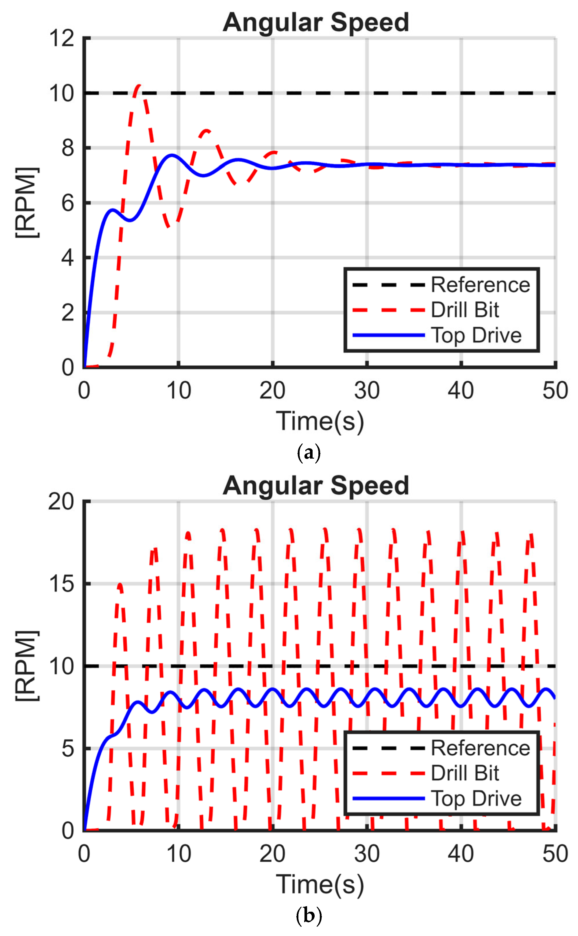
In this paper, three sets of models, varying with the way stiffness and damping were modeled, were carefully tested and simulated against the same input functions, same system parameters, and the same nonlinear rock-bit interaction function (Karnoop model). The parameters of these models were also specifically matched with measurement-while-drilling (MWD) data collected from a drilled well in an Algerian oil field so that the simulations would reflect realistic operating conditions. This comparative study highlighted the effect of significant parameters. It has been demonstrated that the severity of torsional vibrations significantly increases with changing weight on bit (WOB) for both the first model set (only considering stiffness) and the second model set (considering stiffness and damping). This consistency of response across the first two models signifies the predominant role of WOB and drill string stiffness in causing stick–slip oscillations. In contrast, the third set of models involving only damping without any stiffness was remarkably not affected by an increase in WOB with regards to causing or intensifying stick–slip. This finding also concurs with our findings on the indirect limiting role played by damping towards the net severity of torsional vibrations. The simulation scenarios’ results always indicated that the damping coefficient, within the tested ranges, will have no considerable effect on the nature or magnitude of torsional vibrations. However, taking into consideration the damping coefficient used in the model is advisable because it relates to physical mechanisms for dissipating energy along the drill string. Leaving out all the frictional dynamics, although its direct impact on stick–slip severity is proved to be negligible, can lead to a wrong representation of the system’s energy balance. Knowing these specific influences, the behavior and dynamics of the drilling system can be simulated more accurately. Such precision is crucial to develop and implement torsional vibration control without introducing unjustified computational complexity and thereby enhance drilling performance and extend equipment life.
For further improvements, more research should be conducted to consider the spatial deformation and gradients of stiffness along the drill string. The 2DOF model used herein oversimplifies the drill pipe, but a multi-segment approach with non-uniform properties and contact positions would allow for the demonstration of the influence of localized stiffness changes (e.g., at tool joints or due to wellbore curvature) on torsional vibration and high-frequency oscillation. This would generate more efficient mitigation strategies.

Funding

This research received no external funding.

Data Availability Statement

The data presented in this study are not publicly available due to restrictions. However, the data can be made available from the corresponding author upon reasonable request.

Conflicts of Interest

The author declares no conflict of interest.

References

  1. Navarro-López, E.M.; Cortés, D. Avoiding harmful oscillations in a drillstring through dynamical analysis. J. Sound Vib. 2007, 307, 152–171. [Google Scholar] [CrossRef]
  2. Mendil, C.; Kidouche, M.; Doghmane, M.Z. Hybrid sliding PID controller for torsional vibrations mitigation in rotary drilling systems. Indones. J. Electr. Eng. Comput. Sci. 2021, 22, 146–158. [Google Scholar] [CrossRef]
  3. Navarro-López, E.M. An alternative characterization of bit-sticking phenomena in a multi-degree-of-freedom controlled drillstring. Nonlinear Anal. Real World Appl. 2009, 10, 3162–3174. [Google Scholar] [CrossRef]
  4. Ahmadi, K.; Altintas, Y. Stability of lateral, torsional and axial vibrations in drilling. Int. J. Mach. Tools Manuf. 2013, 68, 63–74. [Google Scholar] [CrossRef]
  5. Ullah, F.K.; Duarte, F.; Bohn, C. A Novel Backstepping Approach for the Attenuation of Torsional Oscillations in Drill Strings. Solid State Phenom. 2016, 248, 85–92. [Google Scholar] [CrossRef]
  6. Shen, Y.; Chen, W.; Zhang, Z.; Bowler, A.; Jeffryes, B.; Chen, Z.; Carrasquilla, M.N.; Smith, D.; Skoff, G.; Panayirci, H.M.; et al. Drilling Dynamics Model to Mitigate High Frequency Torsional Oscillation. In Proceedings of the IADC/SPE International Drilling Conference and Exhibition, Galveston, TX, USA, 3–5 March 2020. [Google Scholar] [CrossRef]
  7. Mendil, C.; Kidouche, M.; Doghmane, M.Z. A Study of the Parametric Variations Influences on Stick-Slip Vibrations in Smart Rotary Drilling Systems. In Artificial Intelligence and Renewables Towards an Energy Transition, ICAIRES 2020; Hatti, M., Ed.; Springer: Cham, Switzerland, 2021; Volume 174, pp. 679–692. [Google Scholar] [CrossRef]
  8. Mendil, C.; Kidouche, M.; Doghmane, M.Z.; Benammar, S.; Tee, K.F. Rock–bit interaction effects on high-frequency stick-slip vibration severity in rotary drilling systems. Multidiscip. Model. Mater. Struct. 2021, 17, 1007–1023. [Google Scholar] [CrossRef]
  9. Caballero, E.F.; Lobo, D.M.; Di Vaio, M.V.; Silva, E.C.C.M.; Ritto, T.G. Support vector machines applied to torsional vibration severity in drill strings. J. Braz. Soc. Mech. Sci. Eng. 2021, 43, 386. [Google Scholar] [CrossRef]
  10. Landar, S.; Velychkovych, A.; Ropyak, L.; Andrusyak, A. A Method for Applying the Use of a Smart 4 Controller for the Assessment of Drill String Bottom-Part Vibrations and Shock Loads. Vibration 2024, 7, 802–828. [Google Scholar] [CrossRef]
  11. Shatskyi, I.; Velychkovych, A. Analytical Model of Structural Damping in Friction Module of Shell Shock Absorber Connected to Spring. Shock. Vib. 2023, 2023, 4140583. [Google Scholar] [CrossRef]
  12. Landar, S.; Velychkovych, A.; Mykhailiuk, V. Numerical and Analytical Models of the Mechanism of Torque and Axial Load Transmission in a Shock Absorber for Drilling Oil, Gas and Geothermal Wells. Eng. Solid Mech. 2024, 12, 207–220. [Google Scholar] [CrossRef]
  13. Velichkovich, A.S. Design Features of Shell Springs for Drilling Dampers. Chem. Petrol. Eng. 2007, 43, 458–461. [Google Scholar] [CrossRef]
  14. Volpi, L.P.; Lobo, D.M.; Ritto, T.G. A stochastic analysis of the coupled lateral–torsional drill string vibration. Nonlinear Dyn. 2021, 103, 49–62. [Google Scholar] [CrossRef]
  15. Li, X.; Yu, T.; Zhang, L.; Zeng, H.; Duan, C. Theoretical and Numerical Analysis of Coupled Axial-Torsional Nonlinear Vibration of Drill Strings. Shock. Vib. 2021, 2021, 8046635. [Google Scholar] [CrossRef]
  16. Alsaihati, A.; Alotaibi, B. Determining Severity of Lateral and Torsional Downhole Vibrations While Drilling Surface Holes Using Three Machine Learning Techniques. SPE J. 2022, 27, 1493–1503. [Google Scholar] [CrossRef]
  17. Fang, P.; Ding, S.; Yang, K.; Li, G.; Xiao, D. Dynamics characteristics of axial–torsional–lateral drill string system under wellbore constraints. Int. J. Non-Linear Mech. 2022, 146, 104176. [Google Scholar] [CrossRef]
  18. Barnett, L.; Al Dushaishi, M.F.; Khan, M.F.M.H. Experimental investigation of drillstring torsional vibration effect on rate of penetration with PDC bits in hard rock. Geothermics 2022, 103, 102410. [Google Scholar] [CrossRef]
  19. Zhang, Y.; Zhang, H.; Chen, D.; Ashok, P.; van Oort, E. Comprehensive review of high frequency torsional oscillations (HFTOs) while drilling. J. Pet. Sci. Eng. 2023, 220, 111161. [Google Scholar] [CrossRef]
  20. Barboza, T.R.; Nascimento, A.; Mantegazini, D.Z.; Reich, M. Drilling Optimization by Means of Decision Matrices and VB Tool Applied to Torsional Vibration and MSE Surveillance. Appl. Sci. 2025, 15, 2436. [Google Scholar] [CrossRef]
  21. Canudas-de-Wit, C.; Rubio, F.R.; Corchero, M.A. D-OSKIL: A New Mechanism for Controlling Stick-Slip Oscillations in Oil Well Drillstrings. IEEE Trans. Control Syst. Technol. 2008, 16, 1177–1191. [Google Scholar] [CrossRef]
  22. Attar, F.; Grauwmans, R.; Ikhajiagbe, O. Soft Torque Impact on Drilling Performance in Qatar. In Proceedings of the International Petroleum Technology Conference, Doha, Qatar, 20–22 January 2014. [Google Scholar] [CrossRef]
  23. Kaplan, J. Modélisation Tridimensionnelle du Comportement Directionnel du Système de Forage Rotary. Ph.D. Thesis, École Nationale Supérieure des Mines de Paris, Paris, France, 2003. [Google Scholar]
  24. Abdulgalil, F.; Siguerdidjane, H. Backstepping design for controlling rotary drilling system. In Proceedings of the IEEE Conference on Control Applications, Toronto, ON, Canada, 28–31 August 2005; pp. 120–124. [Google Scholar] [CrossRef]
  25. Ejike, C.; Khizar, A.; Teodoriu, C. Numerical Analysis of Torque on Bit on Torsional Vibrations in Horizontal Well Drilling. In Proceedings of the SPE Oklahoma City Oil and Gas Symposium, Oklahoma City, OK, USA, 14–16 April 2025. [Google Scholar] [CrossRef]
  26. Doghmane, M.Z.; Kidouche, M.; Ahriche, A. Decentralized Overlapping Control Design with Application to Rotary Drilling System. IETE J. Res. 2021, 69, 2070–2079. [Google Scholar] [CrossRef]
  27. Franca, L.F.P. A bit–rock interaction model for rotary–percussive drilling. Int. J. Rock Mech. Min. Sci. 2011, 48, 827–835. [Google Scholar] [CrossRef]
  28. Boussaada, I.; Saldivar, B.; Mounier, H.; Mondié, S.; Cela, A.; Niculescu, S. Delay System Modeling of Rotary Drilling Vibrations. In Recent Results on Time-Delay Systems; Witrant, E., Fridman, E., Sename, O., Dugard, L., Eds.; Springer: Cham, Switzerland, 2016; Volume 5, pp. 13–28. [Google Scholar] [CrossRef]
  29. Ejike, C.; Abid, K.; Teodoriu, C. Scaling Torsional Drilling Vibrations: A Simulation-Based Comparison of Downscale and Upscale Drill Strings Under Varying Torque Conditions. Appl. Sci. 2025, 15, 2399. [Google Scholar] [CrossRef]
  30. Guo, X.; Xiao, S.; Qiu, X.; Li, X.; Hu, N.; Dai, L. Experimental investigation on axial–torsional coupling nonlinear vibration characteristics of multi-body drill string system in oil and gas wells. Nonlinear Dyn. 2025, 113, 19401–19434. [Google Scholar] [CrossRef]
  31. Tian, J.; Xie, Y.; Al-Mamoori, H.N.; Kana, A.D.; Dai, L. Dynamic characteristics and parameter analysis of drill string system with sliding drilling controller. Int. J. Non-Linear Mech. 2025, 171, 105028. [Google Scholar] [CrossRef]
  32. Wang, C.; Chen, W.; Wu, Z.; Li, J.; Liu, G. Stick–Slip Characteristics of Drill Strings and the Related Drilling Parameters Optimization. Processes 2023, 11, 2783. [Google Scholar] [CrossRef]
  33. Tashakori, S.; Vossoughi, G.; Zohoor, H.; van de Wouw, N. Prediction-Based Control for Mitigation of Axial–Torsional Vibrations in a Distributed Drill-String System. IEEE Trans. Control Syst. Technol. 2022, 30, 277–293. [Google Scholar] [CrossRef]
Figure 1. Schematic diagram of the drill string components.
Energies 18 03701 g001
Figure 2. Equivalent system of drill string.
Energies 18 03701 g002
Figure 3. Measurement while drilling of torsional, axial, and lateral vibrations in an Algerian petroleum oil well.
Energies 18 03701 g003
Figure 4. Measurement while drilling of high-frequency torsional vibrations in an Algerian petroleum oil well.
Energies 18 03701 g004
Figure 5. Schema of the rotary drilling system of (a) the first model set, (b) the second model set, and (c) the third model set.
Energies 18 03701 g005
Figure 6. Dynamic responses of the first model set for the angular velocities for the following: (a) Wob = 150kN, and (b) Wob = 250kN.
Energies 18 03701 g006
Figure 7. Dynamic responses of the second model set for the angular velocities for the following: (a) Wob = 150 kN, and (b) Wob = 250 kN.
Energies 18 03701 g007aEnergies 18 03701 g007b
Figure 8. Dynamic responses of the third model set for the angular velocities for the following: (a) Wob = 150 kN, and (b) Wob = 250 kN.
Energies 18 03701 g008aEnergies 18 03701 g008b
Figure 9. Dynamic responses of the open-loop model for the following: (a) η = 70 × 10−3 mPa·s, and (b) η = 35 × 10−2 mPa·s.
Energies 18 03701 g009aEnergies 18 03701 g009b
Figure 10. Dynamic model responses for (a) Lp = 1800 m and (b) Lp = 3600 m.
Energies 18 03701 g010aEnergies 18 03701 g010b
Figure 11. Dynamic model responses for the following: (a) Rr = 0.1120/2 m and rr = 0.1086/2 m (16-inch phase), and (b) Rr = 0.1270/2 m and rr = 0.1086/2 m.
Energies 18 03701 g011aEnergies 18 03701 g011b
Figure 12. Dynamic model responses for the following: (a) Lb = 100 m, and (b) Lb = 200 m.
Energies 18 03701 g012aEnergies 18 03701 g012b
Figure 13. Dynamic model responses for the following: (a) Rb = 0.2159/2 m; rb = 0.0564/2 m, and (b) Rb = 0.1524/2 m; rb = (0.0564 ± 0.05)/2 m.
Energies 18 03701 g013
Table 1. Parameters used for simulation scenarios.
ParameterValueUnit
K 473 N · m / r a d
j r 2122 K g · m 2
j b 374 K g · m 2
C 1 50 N · m · s / r a d
C 2 425 N · m · s / r a d
C23.2 N m   s / r a d
Q r e f 10 /
W o b 250 k N
u10 × 103N
Disclaimer/Publisher’s Note: The statements, opinions and data contained in all publications are solely those of the individual author(s) and contributor(s) and not of MDPI and/or the editor(s). MDPI and/or the editor(s) disclaim responsibility for any injury to people or property resulting from any ideas, methods, instructions or products referred to in the content.

