Review

Utility Transformer DC Bias Caused by Metro Stray Current—A Review

by
Adisu Makeyaw
1,
Xiaofeng Yang
1,*,
Xiangxuan Sun
1,
Ke Liu
1,
Tianyi Wu
2 and
Lu Chen
2
1
School of Electrical Engineering, Beijing Jiaotong University, Beijing 100044, China
2
State Grid Shanghai Electric Power Research Institute, Shanghai 201199, China
*
Author to whom correspondence should be addressed.
Energies 2025, 18(14), 3678; https://doi.org/10.3390/en18143678
Submission received: 9 June 2025 / Revised: 30 June 2025 / Accepted: 9 July 2025 / Published: 11 July 2025
(This article belongs to the Topic Power System Protection)

Abstract

The rapid expansion of the urban rail network has increased concerns regarding stray current generated by the DC traction power supply system. This stray current, which arises from inadequate insulation between the rail and the ground, can cause electrochemical corrosion and operational challenges to nearby buried metallic infrastructures. A portion of stray current entering utility transformers may induce DC bias risk, thereby affecting the stability and reliability of distribution networks. This review studies the trends in utility transformer-related DC bias caused by metro stray current. Various modeling approaches and suppression measures are discussed, with an emphasis on comprehensively understanding stray current distribution behavior, the DC bias coupling loop, and its impacts. This review underscores the need for a thorough evaluation of existing DC bias suppression measures, and more effective and efficient measures must be developed to enhance the resilience of distribution networks. The gaps in current research are highlighted, and further studies are advocated, particularly those focusing on dynamic metro conditions, supported by advanced modeling, field applications, and interdisciplinary collaboration, to address the challenges of DC bias in urban rail environments.

1. Introduction

The urban rail transit (URT) system, including the light rail, monorail, metro, and tram, plays a crucial role in modern urban infrastructure by improving mass transportation efficiency and promoting sustainable development [1,2,3]. A metro network reaching a mileage of more than 41,000 km have been employed in 157 cities throughout the globe by the end of 2023. Notable examples are core cities like Beijing, Tokyo, New York, and London, which have intricate metro systems that span more than 70% of their urban areas [4,5,6]. Recently, China’s URT lines reached 11,232.65 km, with 884.55 km of newly opened lines, 60.1% of them being metro lines [7]. While the metro significantly enhances urban transportation, it also gives rise to certain issues that entail serious attention [8,9]. Stray current, which arises due to inadequate insulation between the running rails and the ground, is attracting growing concern [10,11]. As part of the rail current [10], stray current leaks into the ground via unintended paths, potentially causing significant adverse effects on nearby buried metal pipelines [12]. The electrical hazards associated with the rail potential and stray currents [13]—such as electrochemical corrosion of buried oil and gas pipelines, as well as severe damage to the underground infrastructure, like cables [14] and nearby metals [12,15]—have been major concerns for global scholars studying urban railways over the recent decades [11,16,17]. With the rapid expansion of metros, stray current poses challenges to metro operations and the integrity of pipelines and utilities. The summary of the broad impacts is shown in Table 1.
The stray current interferes with the neutral point grounding of the utility transformer, leading to the circulation of DC components within the transformer’s winding. This results in DC bias, thereby influencing the safety and stability of the utility grid [30]. As indicated in Figure 1, from the metro side, the stray current generally interferes with the transformer’s neutral point on the utility side via metro grounding, buried pipelines, and electrical metallic transmission paths between the grounding of the metro and utility grid [27,38,39]. The grounding of the main and traction substations may form a metallic connection path through overhead ground wires or cable armor, and the utility grid’s grounding network can also be directly connected to the grounding of transmission towers and cable shield metallic layers [38]. Moreover, reduced insulation may cause the metro rail to be indirectly connected to ground, thereby establishing a conductive path for stray current intrusion between the metro and the grounding of utility transformers. Consequently, the metro stray current may propagate among different substations through transmission lines and cable armor conductors [40]. The neutral point current waveform of utility substations in different geographical locations has exhibited similarities, suggesting the existence of a metallic interference path for stray current in metro systems supplied by utility substations for lower distribution networks [38]. Thus, the utility transformer DC bias is caused when the metro stray current reaches and circulates in the windings of the utility transformers by any of the coupling mechanisms [29].
The presence of a DC bias in a utility transformer can lead to increased losses, temperature, noise, and vibration, and influence the grid system, which can even cause malfunctions in relay protection equipment [41,42,43]. It further results in severe distortion of the transformer excitation current, increased harmonic content, and exacerbated vibration, thereby reducing its service life [9,44,45]. When the system is exposed to odd and even harmonic current, the reactive power demand of the system also rises, thereby causing voltage fluctuations in the power system to a certain extent, and voltage collapse may occur in severe cases [46]. As a result, DC bias endangers the operation of the utility grid system [41,42,47]. Thus, it can easily be understood that this phenomenon will eventually lead to the risk of transformer failure and a significant loss of maintenance costs, as well as efficiency and reliability issues in power distribution networks [27].
With the increasing mileage of metros, the power supply demand in megacities is also increasing; for example, in Shanghai, China, there are seven utility substations with grounding systems exceeding 220 kV [48]. Furthermore, a 500 kV substation in Shanghai comprises 11 distribution networks at the 110 kV level, highlighting the significant electrical coupling between the metro and main substations [49]. Similarly, as noted in [40], a city in southwest China with nine metro lines, has a city grid including seven 500 kV substations and 61 220 kV substations. Notably, 22 of these 220 kV substations are electrically coupled to the corresponding metro traction substations via cable armor layer conductors. This coupling phenomenon exacerbates DC bias issues, which become severe and require a sustainable solution. Further research has demonstrated that metro systems are a leading cause of DC bias in utility transformers [9,28,32,43,50,51,52,53].
The issue of DC bias in utility transformers with neutral point grounding has been reported in various Chinese cities such as Shanghai [32], Guangzhou [54], Shenzhen [30], Fuzhou [55], Dalian [28], Chengdu [56], Jiangxi [27], Changsha [26,50,57], and others [58]. In the State Grid of Hangzhou Power Supply Company, Zhejiang, the abnormal operation of a 220 kV substation utility transformer was observed [9]. The noise level was increased by 20 dB from the normal level, reaching more than 80 dB, and was confirmed to be consistent with the metro operation time. The maximum current exceeded 50 A during the daytime. It was found that an abnormal noise emanated from the No. 1 main transformer grounded on the 220 kV side of Hangyun Station, and the noise appeared periodically with the operation time of the metros [45]. Similarly, in Guangzhou, complaints have been reported about utility transformers’ disturbances caused by DC bias; the positive and negative maximums of DC are concentrated at 07:00~09:00 AM and 18:00~20:30; with the highest value of the metro DC reaching 50 A, and with the neutral point current of 21 A, a maximum of 98.8 dB was recorded for the utility substation which is a distance of 4 km from the metro [54]. According to the relevant standards, the neutral current at a 220 kV transformer should not exceed 4 A [59,60]. The neutral point of the main transformer at Shenzhen reached nearly 30 A, with the transformer noise increasing from 68 dB to 81.2 dB, and even harmonics appeared on the low-voltage side [61]. The maximum neutral current of a 220 kV main transformer in Beijing reached 16.29 A, and the maximum negative DC component was 19.41 A, which occurred at 7:00~8:00 AM, causing the DC bias phenomenon [51]. Field testing of the Changsha 220 kV substation transformer also showed the neutral point current approaching 44 A, which is also consistent with the operation time of Metro Line 1 [50]. The extreme amplitude of the stray current reached about 114 A at the neutral point of the No. 5 main transformer of the 220 kV Shuibei substation. The noise level of the main transformer was recorded as 84 dB [39], and the transformer neutral current in the Shenzhen power grid reached 83 A, resulting in severe DC bias impacts [33]. Although existing works have contributed to the understanding of noise and vibration characteristics, as well as spectral analysis before and after the DC bias [62,63,64], there is a need for integrated data analysis techniques and a thorough exploration of suppression strategies to enhance transformer reliability and safety. Thus, in general, the fluctuating inclination of the neutral current throughout the day reveals a strong parallel between the neutral current and metro traction current. The exact experience of the metro is shown by the neutral current staying close to zero during the metro lines’ non-operational hours (00:00–6:00 am) and regularly above the threshold (4 A) [44] during the metro’s regular operating hours (20:00–22:00). In peak hours (17:30–19:30), the highest amplitude of the neutral current can even exceed 9.88 A, surpassing twice the threshold value, and further studies indicate the neutral point DC reaching 30.2 A at the peak of operation [4,65]. Particular explorations on the implementation of advanced real-time monitoring systems and the utilization of predictive modeling strategies are helpful for maintenance scheduling of these evolving problems.
Some of the current solutions to the emerging issues of DC bias comprise a DC-blocking device, which has been applied in the grounding neutral point of the 500 kV main transformer of the Shenzhen substation to suppress the intermittent noise of the transformer to a certain level [52]. An active converter has been combined with the blocking capacitor to suppress bias and excessive harmonics [66]; however, the blocking device has an impact on other transformers without blocking devices located near the metro area, inevitably leading to indirect grounding of the neutral points. A silicon carbide PiN diode-based DC bias-blocking measure has been analyzed by testing the ground potential distribution [67]. On the other hand, the DC-limiting resistor connected in series with the neutral point of a 500 kV transformer in Shanghai shows a better DC bias suppression effect [53]. Furthermore, a reverse DC injection device based on a high-frequency switching power supply was introduced to suppress the DC bias effectively [68]. While these methods mitigate the DC bias issue to some extent, they also introduce new challenges to power grid operation [69]. For instance, the DC-limiting method proposed in [70] affected the reliable grounding of the power grid system; if the resistance value of the neutral point is too significant, it may lead to overvoltage of the transformer neutral point, indicating a gap in determining the appropriate limiting resistance value. A potential compensation method, comprising a reverse DC countering the bias current, has been proposed [71]; however, the accurate reverse current has not yet been researched. Research is ongoing to explore effective and efficient suppression measures for DC bias [40,44,52,72,73,74,75,76,77,78]. The details of the discussion are put forward in the fourth section of this review article.
Given the safety and reliability requirements of the power system, the DC bias current limit for utility transformers, based on practical HVDC experience in Guangdong, Yunnan, and Hubei provinces, is set at 4 A [44]. Besides, according to the provisions of the “Technical Guidelines for High Voltage DC Grounding Electrodes” DL/T 5224—2014, the allowable DC of single-phase, three-phase five-column, and three-phase transformers is 0.3%, 0.5%, and 0.7% of the rated current [9,51]. However, there is no explicit regulation regarding the allowable value of DC injection in transformers caused by stray current from the metro [9]. When the DC flowing through the transformer winding exceeds the specified acceptable threshold, appropriate measures must be taken to address the issue. Thus, DC bias current generally impacts the grid and distribution networks, including the utility transformers. Additionally, according to the GB/T 1094. 10-2003 “Power transformers-Part 10: Sound level determination” guideline, a vibration exceeding the environmental noise emission standard, which should be ≤65 dB, will have a severe impact on the residents and personnel as well [9]. While existing guidelines address the impact of sound levels, there is a lack of focus on the cumulative effects of DC bias on transformer performance and grid stability. Future research should aim to establish comprehensive standards for DC bias limits and their operational implications. Integrating real-time monitoring systems to assess DC levels and vibration impacts can enhance predictive maintenance strategies, ultimately improving the reliability and safety of power distribution networks.
It is known that utility transformers are the main components of distribution networks that transform voltage and distribute energy [79]. Hence, for sustainable urban safety, research has been conducted to find solutions for reducing the far-reaching effects of stray current on utility transformers [36,37], including international concerns like regulations and standards-setting [80], which are the ongoing efforts by experts to enhance cooperation between electric utilities and urban rail transit systems. Current research shows that the pervasive impacts of stray current require an inclusive solution. Recent research on metro stray current mainly focuses on the distribution characteristics of stray current and rail potential [8,81,82,83]. Remarkably, domestic and global research concerning DC bias predominantly investigates the generation mechanisms of DC bias from various sources, including HVDC [44,46], GIC [84], and metros [32,35]. These studies also examine the effects of DC bias on utility transformers [8,9,28,43,45,46,51,53,74], and suppression measures [44,52,67,75,77,78,82,85]. However, potential gaps observed in these works include the need for comprehensive studies that quantify DC bias from metro systems, a lack of field validation for theoretical models, inadequate interdisciplinary integration, and limited effective suppression strategies. Moreover, there are issues with measurement standardization, long-term impact assessments, and collaboration between metro authorities and utilities. Addressing these gaps is crucial for a better understanding and management of DC bias in utility transformers. Additionally, as train operation is dynamic, the DC bias caused by the metro must be suppressed according to the metro’s characteristics and requires special attention [45,86]. Furthermore, DC bias caused by HVDC systems occurs only under specific operating conditions, such as unipolar ground return modes during system failures or maintenance, with generally short and predictable durations. In contrast, DC bias caused by metro stray current persists as long as the metro system remains operational [9,50]. Thus, due to the longer duration of transformer DC bias caused by metro systems compared to HVDC and GIC, the utility transformer DC bias issues caused by stray current require further system-level research and evaluation.
Therefore, this review paper aims to discuss the abovementioned utility transformer DC bias issue caused by metro stray current. It involves characterizing stray current, modeling its impact on transformers, investigating the various effects of DC bias, reviewing potential suppression measures, and highlighting gaps for prospects. This aligns with the intended target, including electric utilities, metro operations, transformer manufacturing, and urban planning authorities. Thus, it contributes by providing a comprehensive overview of the causes and effects of DC bias in utility transformers, critically evaluating existing measures, detailing their effectiveness and applicability, and identifying key areas for future research to enhance suppression techniques and improve power grid resilience and environmental safety. The methodology will comprise a literature review, evaluation, detailed study of the DC bias mechanism, and comparison of corresponding suppression measures with their schematics. A specific criterion is used to select sources relevant to the review topic, which includes relevance to urban rail and its impact on nearby infrastructure, relevance to urban rail’s impact on utility transformers, publication in peer-reviewed journals, recent studies to ensure contemporary relevance, and studies that provide both quantitative and qualitative data on DC bias phenomena. The subsequent sections of the review are structured into five main sections: stray current and its impact, the mechanism and impacts of DC bias on utility transformers, suppression measures for DC bias, challenges and future directions, and finally, the conclusion.

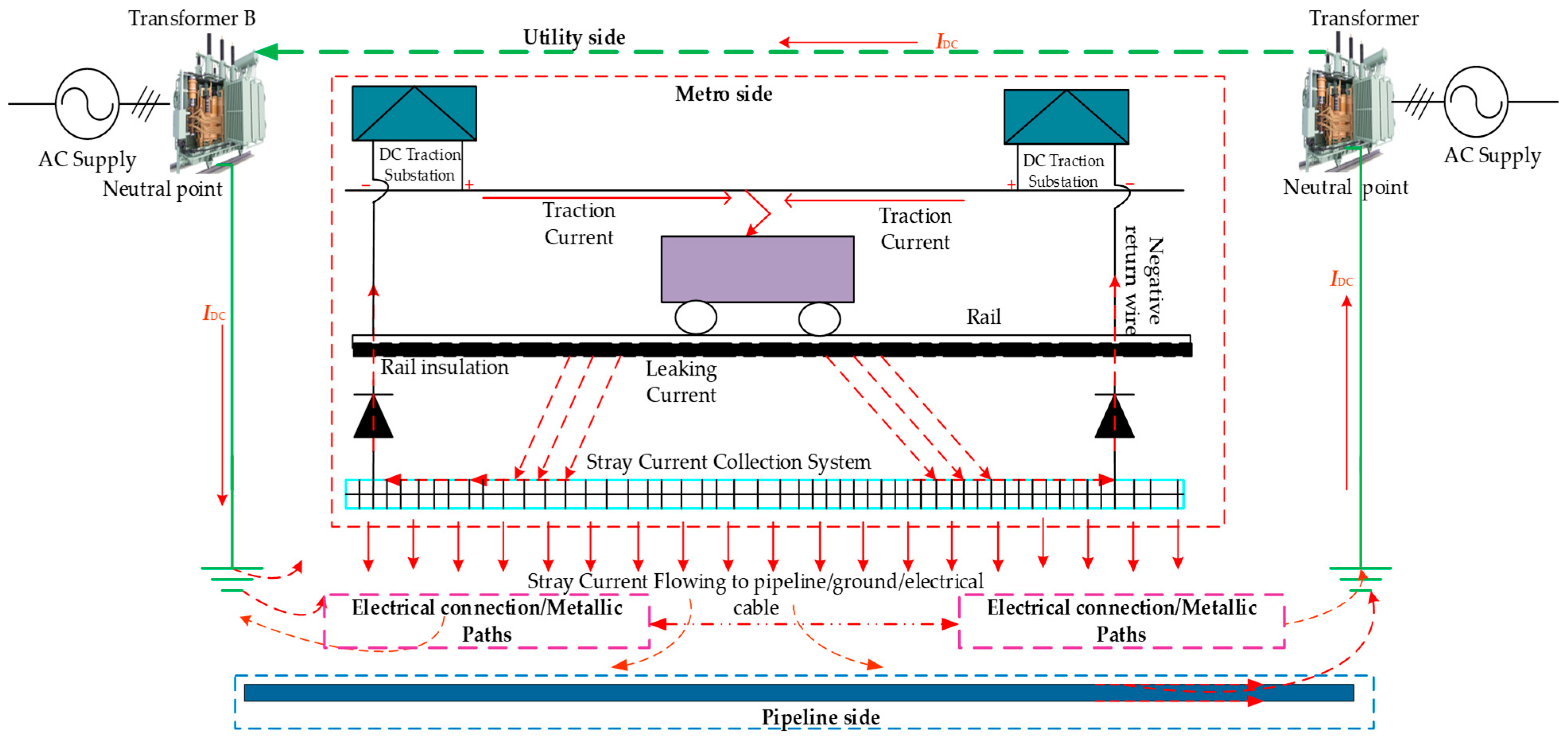
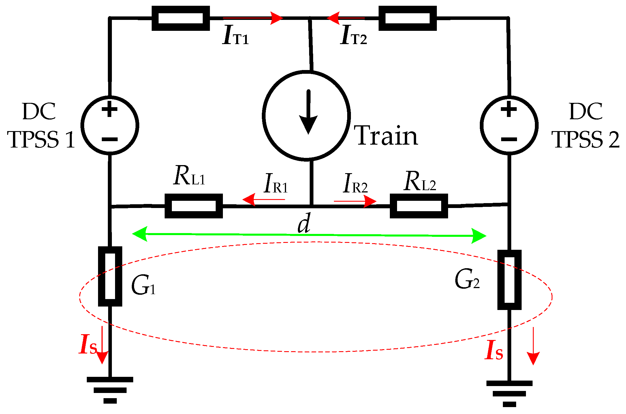
2. Stray Current and Its Impact

Stray current in the DC traction power supply system is a common issue due to the imperfect insulation of the running rails [17]. The asymmetric distribution of the traction current and poor rail-to-ground conditions of the traction power supply system (TPSS) may also generate stray current [19]. Furthermore, in closed metro tunnels, new conductive pathways may form between the rail and the earth due to the accumulation of carbon dust caused by the sliding electrical contact between the pantograph strip and the catenary [87]. These rudiments may cause the 750 V, 1500 V, or 3000 V DC traction reflux to leak from the rail into the ground, creating the so-called stray current, which fluctuates momentarily in tandem with the metro vehicles’ traction situations. Most metro systems utilize running rails as the current return path, and the rail potential increases the leakage current, thereby intensifying the risks of stray current [10].
As shown in Figure 2, the leading factors causing stray current in DC-electrified rail transit include the traction current (IT1, and IT2), rail return current (IR1, and IR2), longitudinal resistance of the running rails (RL1, and RL2), conductance between rail and ground (G1, and G2), distance between substations (d), and rail-to-rail cross-bonds [11,16]. According to the International Electrotechnical Commission (IEC)’s standard, the most important factor affecting stray current is the conductance between the rail and the ground [88]. According to the standard DS/EN 50162:2004, decreasing the conductance of G1 and G2 is one solution for reducing stray current. For new lines, the standard “CJJ/T49—2020” stipulates that the rail-to-ground resistance should not be less than 15 Ω.km; for the running lines, it should not be less than 3 Ω.km [89,90], and the transition resistance with the structure of insulation, monitoring, and drainage should be over 5 Ω.km [91]. Increasing the supply voltage is another method for reducing stray current. Under the same power rating of the TPSS, IT decreases along with the increase in TPSS voltage, and as IT decreases, IR also decreases [11]. As shown in Figure 2, the stray current IS is part of the rail current, so it will decrease as it is directly related to IR. The other factor is the distance or spacing of rail-to-rail cross-bonds, which maintain an equipotential with adjacent rails and affect the distribution of stray current. To insulate the rail from the ground and reduce the rail current’s leakage, concrete sleepers, side column insulators, insulating clips, and rail cushions are commonly used [19,22]. The distance of traction substations from the rail can also affect the pathways of stray current. As the distance increases, a greater proportion of current may seek other routes back to the negative terminal. These factors can be summarized as substation design, rail, train operation, and the surrounding geological environment [92]. Thus, the overall system design of the critical parameters of the traction power supply system, like the longitudinal resistance of the running rails (RL1 and RL2), distance of the substations (d), spacing of rail-to-rail cross-bonds, and other influencing factors, are essential for careful design and maintenance to reduce their impacts [11,17].
As stated in Table 1, stray current has numerous disadvantages, making the mitigation of this current of paramount importance. Several works, including the installation of a stray current collection mat (SCCM), fourth rail, and return cables instead of running rails, have been investigated to show the effects of stray current on nearby infrastructure, and ongoing research focuses on potential mitigation methods, providing a comprehensive comparison and evaluation of these techniques [10,15,18]. At present, there are generally two ways of stray current mitigation in URT: source control and drainage methods [93]. These mitigation methods are often used in combination in the design of URT. Currently, highlights on how the zero-resistance converter system (ZRCS) mitigates stray current effects have been provided by constructing zero-resistance loops that transfer return current from running rails to specific return cables using a time–frequency analysis method based on the S-transform to evaluate the dynamic stray current [94]. Universal safety measures and international standards are established to mitigate the damaging effects of stray current that circulates uncontrolled in conductive materials and structures [95]. A comprehensive overview of guidelines and standards for limiting stray current, along with recommendations, is also provided [96]. If the DC traction system meets the requirements and measures of the IEC 62128-2 standard, it has been assumed to be acceptable from a stray-current standpoint [88]. It has been predicted that the proportion of stray current after collection with the SCCM is 0.05%~0.21% of the traction current [91].
On the other hand, a stray current less than the average limit stipulated in “CJJ/T49—2020”, i.e., 2.5 A/km, will have a severe impact on the utility side [90]. Additionally, as the distance of the substation increases, the rail’s resistance will also increase, which increases the rail potential [93]. From the ungrounded (floating), thyristor-grounded, diode-grounded, and solidly grounded schemes, the solidly grounded system produces the lowest rail potential [96]. Despite this, the excessive stray current resulting from frequent activation of the overvoltage protection device (OVPD) has extremely increased the corrosion of buried metal and transformer DC bias [92]. As shown in Figure 3, when the diode connecting the rail to the ground is forward-biased, DC intrusion with the nearby utility transformer will occur. To effectively address the extensive and far-reaching impacts of stray current, it is essential to first investigate the influencing factors that govern its distribution. Subsequently, a theoretical model should be developed to elucidate the relationship between stray current and these influencing variables.
The analytical method [97], finite element analysis, and simulation [98] are the fundamental approaches for a detailed study of stray current and rail potential. Researchers have developed models to simulate the dynamic distribution of rail potential and stray current under various metro operation conditions, such as the number of trains in operation [18]. Some mathematical modeling and analysis approaches for stray current are the modeling of resistor networks, like two-layer (rail–earth), three-layer (rail–drainage net–earth), and four-layer (rail–drainage net–metal structure–earth) models [10,53], and the finite element method (FEM) [20]. Based on real-time traction conditions, the dynamic process of the stray current influence on buried pipelines is studied using the multi-physics FEM, and this FEM simulates the pipeline-to-soil potential under varying stray current conditions, allowing for the analysis of how this current influences the corrosion rate [99]. While the metro pipeline side has been well-analyzed, gaps in the integrated modeling of the utility side require attention. The current leakage and distribution laws at the mainline and metro depot are analyzed using a field-circuit coupling method, and mitigation actions are suggested for high-risk zones in both locations [59]. Though the spread of stray current and high-risk scenarios (e.g., gauge block insulation failure and OVPD operational status) that exacerbate stray current leakage are addressed, extended modeling benefits include time-varying traction loads and their impact on transformer-neutral DC currents, particularly during peak subway operation. By incorporating parameters such as soil resistivity gradients and grounding system design, future studies could integrate the field-circuit coupling method with power grid models to simulate how subway stray currents induce DC bias in transformers.
A multi-section model has been developed to analyze stray current in DC metro systems [98]. The model provides a realistic basis for assessing DC intrusion into power grids by capturing dynamic stray current characteristics across an entire metro line. The periodicity of stray current and soil/resistance dependencies can be key takeaways for advanced studies. Researchers have contributed to the derivation of the stray current distribution function, building an equivalent circuit, and the deduction of a numerical calculation formula [100]. It is worth highlighting that transforming stray current monitoring into a predictive tool for ensuring DC bias management grid reliability in urban rail environments is beneficial. Future research may reveal that bridging the gap between metro stray current and transformer impacts can lead to the development of holistic frameworks for mitigation.
A three-layer resistance network model composing the rail resistance, drainage network resistance, ground resistance, transition resistance between the rail and the current drainage, transition resistance between the current drainage and the ground and the stray current flowing through the soil, transformer neutral point, and transmission line equivalent resistance has been developed to compare the calculated and simulated values of the neutral point current [27,101]. However, the potential solutions for suppressing the DC component originating from the metro system have not been provided. Furthermore, to improve the network representation, it is feasible to explicitly incorporate transition resistances and grounding effects into the model. When the drainage network fails to collect the stray current completely, the possibility of transformer DC bias will be certain, so a DC bias resistance branch is added to the stray current distribution model, connecting the transformer’s grounded neutral point with the drainage network [27]. The model, as shown in Figure 3, is designed with the resistance components of each network, enabling a mathematical analysis based on the parameters. It presents a comprehensive resistance network model that clarifies the interactions between the DC traction power supply system and utility transformers. It defines the pathways through which stray current enters the grounding systems, affecting the neutral point of utility transformers, and incorporates key resistance components, including the longitudinal rail resistance and transition resistances, which collectively govern the distribution of stray currents and exacerbate DC bias phenomena within transformer windings, potentially leading to operational instability and degradation of transformer performance. Factors such as the material properties, cross-sectional area, length, and temperature of the rail can influence the resistance. The impact of each equivalent resistance and conductance on the ground current distribution characteristics is analyzed [101]. The transition resistances at each node account for the effects of grounding and stray current paths. A comprehensive analysis is necessary to determine the impact of each equivalent resistance on the ground leakage current. Exact modeling of the resistances is more realistic for adapting to changing environmental conditions, such as soil characteristics and temperature variations, that affect the neutral point current. So far, in this section, the origin, distribution, and effect of stray current in DC TPSS, particularly in URT, have been explored. The key influencing factors, mitigation strategies, and modeling approaches are highlighted. The need for integrated modeling to address gaps in the discourse on DC bias in utility transformers is underscored, and advanced monitoring and predictive tools are advocated for effectively managing the influence of stray current.

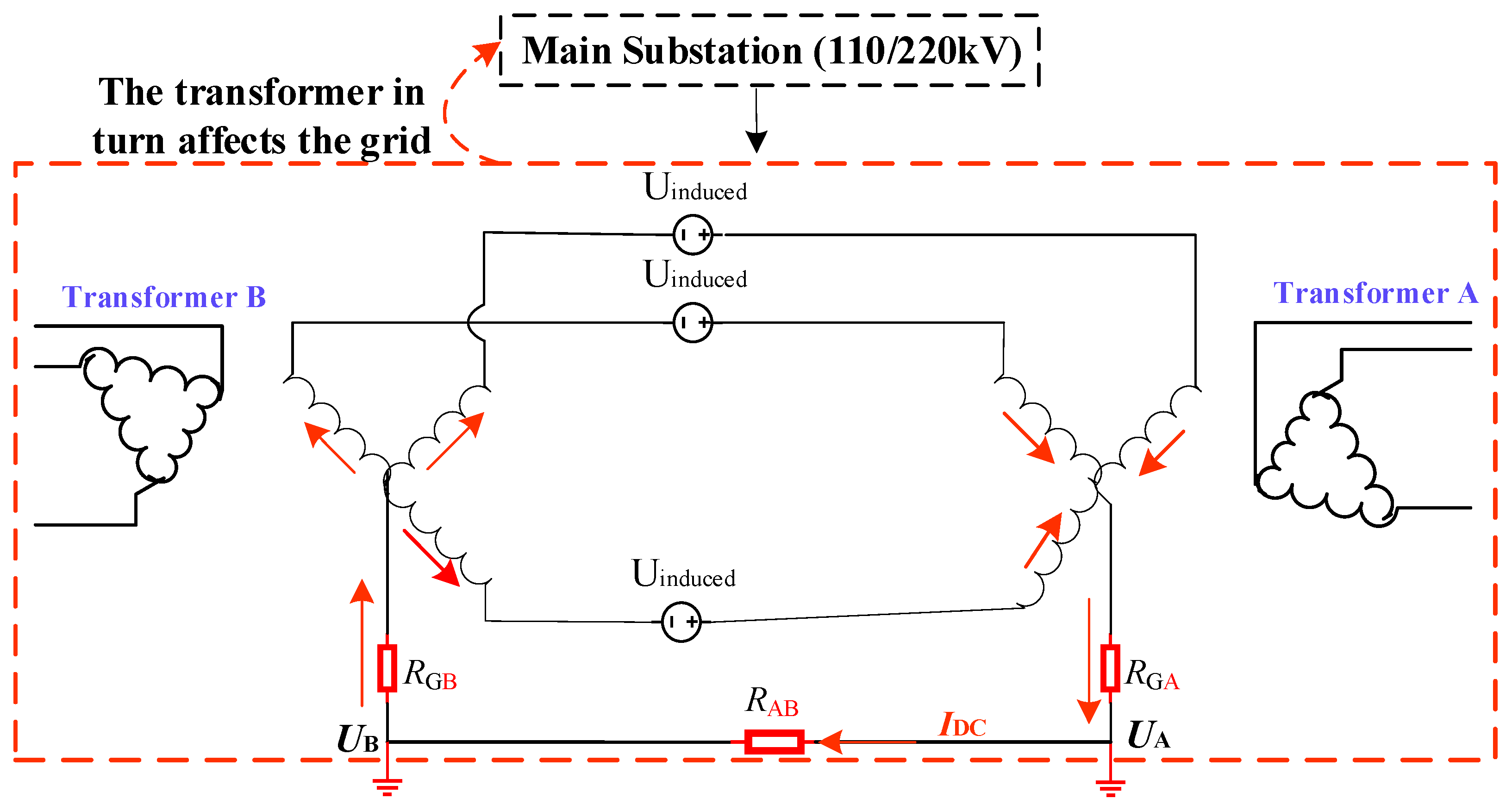
3. Mechanism and Impact of DC Bias on Utility Transformers

DC bias in a utility transformer refers to the abnormal distribution of flux within the transformer, which arises due to a DC offset in the magnetic flux. This condition leads to an imbalance in the operational performance of the transformer core. Several factors contribute to the DC bias phenomenon. Among them, four primary factors have been identified: GIC resulting from solar magnetic storms [102]; HVDC [44]; a varying phase shift ratio in the transient state of converters [103]; and metro stray current [45].
When the train is running, the drainage network returns part of the stray current to the traction substation, but some of it still leaks into the ground. Thus, this part of the current passes through the soil or a buried metal pipeline [29] and finally enters the neutral-grounded transformer. The utility transformers are impacted when the train’s current leaks from the DC traction power supply system and flows into the ground, changing the surrounding ground’s surface potential [27]. This surface potential affects the grounding potential of transformers, resulting in a potential difference between them.
The schematic illustrated in Figure 4 demonstrates the DC bias phenomenon of the transformer that results from each substation creating a DC loop via the transformer and the transmission line when the utility transformer’s neutral point is grounded. As the network model incorporates resistance and soil parameters, the current distribution can be easily analyzed based on the existing two-layer, three-layer, and four-layer (Figure 3) models of stray current [10]. The DC bias loop is mainly based on the resistance branch between the drainage network and the neutral point grounding [29,104]. Additionally, for the electricity transmission between the 220 kV and 110 kV levels, there is a cable wire of 110 kV. The cable is equipped with a grounded metallic layer serving as protection for the conducting cable. Hence, the metal protective layer of the cross-bonded cable and the neutral point of the utility transformer are connected through a ground bus, allowing for a DC intrusion [105]. The direct current flowing through the path of the neutral point between the two transformers with a transmission circuit can be calculated as follows:
I DC = U R GA + R GB + R DCA + R DCB + R AB U = U A U B
where UA and UB are the potentials at the grounding path of the two transformers’ DC circulation, U is the potential difference, RGA and RGB are the transformers’ substation grounding resistances, RDCA, and RDCB are the two transformers’ winding DC resistances per phase, and RAB is an equivalent resistance between the transformers, including the earth’s leakage resistance. According to Equation (1), which is based on Ohm’s law, a higher resistance value combined with a lower potential difference U restricts the DC flow to the utility transformer, which is the basis for adopting DC-limiting devices for suppression [106], while the reverse DC injection encounters potential gradients [71]. Conversely, a lower resistance permits increased DC flow, which may potentially lead to the adverse impacts associated with DC bias. The equation is consistent with prior research [27,29,38], which captures the critical role of resistance in determining the magnitude of DC intrusion. The field measurements have shown that higher resistances limit the bias current, as predicted by the equation [32]. With the given equation, steady-state conditions and linear resistances are explicitly assumed, which facilitates the easy identification of the significant parameters influencing the DC bias on the pipeline and utility sides. Meanwhile, dynamic train operation and soil resistance variation models are used to enhance the time-dependent parameters for future studies. Furthermore, although these are minimal for DC bias analysis, inductive and capacitive effects need to be considered at higher frequencies.
After the metro stray current flows into the ground, it subsequently enters the AC utility grid via the neutral point of the transformer, thereby causing an increase in the ground potential difference. The utility transformer neutral point current is primarily influenced by the DC stray current [86]. The magnitude and direction of the DC at the neutral point of the transformer dynamically influence the transformer, making the stray current-based DC bias more complex than the HVDC [50]. The primary factors contributing to changes in the polarity, magnitude, and oscillation frequency of the DC bias current and potential from the metro side include the time-varying traction current, train position, train operation schedule, number of trains, rail resistance, rail–ground transition resistance, and drainage network [45,107]. According to the field tests, only a small amount of DC flow will seriously affect the regular operation of the AC power system, which particularly coincides with the metro’s operation time, particularly at 8:00–10:00 AM and 14:00–16:00 [28], and transformer noise has been caused by a small DC of about 1 A [76]. According to the study’s results [53], a single train has caused a maximum bias current of 2.3 A in a 500 kV transformer, and a maximum magnetic bias current of 12.4 A when multiple trains operate in both directions [56]. On a single metro line, with an increase in the number of trains, the induced current in the loop tends to be saturated. Moreover, the traction characteristics of multiple trains have a more significant impact on the generation of stray current than the number of trains in the line, which impacts the amplitude of stray current intrusion into the grid [39]. The influencing factors that cause a significant increase in ground potential are the train current, the longitudinal resistance of the rail, and the distance between the train and the utility transformer [35]. The relationship between the metro rail potential and neutral point direct current in nearby transformers is analyzed [108]. However, as the study assumes uniform soil resistivity (300 Ω·m), seasonal moisture changes or heterogeneous geology that may alter the stray current have not been considered. Beyond the instantaneous neutral point fluctuation, the cumulative impacts (transformer aging and insulation degradation) for prolonged DC bias are not discussed. Moreover, comparative analysis applied for the broader validation of diverse metro designs is beneficial. The rail longitudinal and ground transition resistances are the key influencing factors of the DC bias risk of urban transformers [109]. However, the existing studies underprovide for the inclusive consideration of the most significant factors. Thus, to evaluate this accurately, the actual operating conditions of the metro should be fully considered in the modeling and analysis.
The resistivities of the concrete and soil influence the process according to the flow path of stray current intrusion into the AC utility transformer [49]. In the coupling area, the tunnel, the concrete, the structural reinforcement, the grounding resistance [44], the neutral point potential, and the position of the transformer along the metro determine the extent of the bias current distribution. Furthermore, the resistance of the pipeline, electrical connections, and other possible metallic transmission paths in the grounding path of the regional utility substation near traction substations influence the magnitude of the bias current. When the earth’s resistivity near the grounding transformer decreases, the DC at the neutral point increases [110]. As the stray current of the metro can flow between different substations through transmission lines, the conductance of lightning protection wires and cables is another factor to be considered [40]. The impact of metro stray current on the DC bias of transformers in the region, through calculations and experiments based on the characteristics of the Shanghai power grid, has been studied [32], emphasizing the importance of regional factors in assessing and responding to DC bias risks, while the gaps, such as the few time frames of measurements, which may not capture seasonal variations in long-term stray current impacts, inadequate provision of transformer specifications, and statistical analysis focusing on averages and extremes (which have to consider train schedules and grid load conditions) are to be addressed as well.
The other factors are the grid topology and design characteristics of the transformer. A dynamic coupling finite element model of a metro line and grid circuit was established to observe the effect of grid topology on stray current affecting the transformer. According to the topological connection between nodes, the typical utility grid structure can be divided into three types: radial, chain, and ring. Based on the model, stray current most impacts the radial structure, and the overall influx of stray current into the grid intensifies with an increase in the number of grid loops [111]. For the transformer design, as the leakage reactance of the utility transformer increases, the stray current flowing to the transformer decreases, and the DC voltage at the neutral point decreases [110]. The wiring configuration of the transformer and the operation mode of the neutral point will also affect the DC distribution. For instance, if the transformer’s neutral point is directly grounded, grounded by a DC suppression device, not grounded at all, or grounded by a small resistance/small reactance, it will have varying effects on the DC distribution characteristics [44]. The transformer type is also another factor to be considered. The three-phase bank and five-limb transformers exhibit a limited capacity to withstand DC bias, leading to excitation current distortion and potential overheating [112]. In contrast, the three-phase, three-column transformer can handle DC bias more effectively, resulting in reduced distortion and improved operational stability. However, studies incorporating the behavior of larger, three-phase transformers are more applicable in real-world grids. Furthermore, future studies should investigate the DC entering through the transformer neutral point, rather than simply injecting it into the primary winding, which would make the analysis more realistic. Additionally, when considering transformers with varying loads, it would be advantageous to indicate the DC bias effects instead of the open-circuit conditions. A thorough investigation into the impact of DC bias on the accuracy, saturation, and thermal behavior of current transformers has provided valuable insights into the underlying mechanisms by which DC bias affects the performance of these transformers [113]. However, the study focuses solely on current transformers, which are less commonly affected by DC bias than utility transformers, and it does not offer potential solutions for addressing the DC bias in current transformers.
When stray current induces a DC voltage in the windings of nearby utility transformers, the transformer’s total flux will combine the AC and DC fluxes, where ϕtot is the total superimposed flux, and ϕac is the flux in the core during regular operations. Based on Faraday’s law and the superposition principle in electromagnetism, where Uac is the sinusoidal AC excitation, NP is the number of primary turns, and C is the integration constant:
U a c = U max sin ( ω t ) = N P d ϕ tot d t ϕ a c ( t ) = U max N P ω cos ( ω t ) + C
The current IDC, from Equation (1), creates a constant magnetomotive force (MMF), which in turn generates a DC flux.
M M F D C = N P I D C ϕ D C = M M F D C = N P I D C
Then, the total flux will be the sum of the AC and DC components.
ϕ tot ( t ) = ϕ a c + ϕ DC
where is the core reluctance, ϕDC is the DC flux, and ω is the angular frequency of the utility transformer. It has been demonstrated that when the DC flows into the transformer, the core magnetic field generates a DC bias flux, which leads to the magnetization curve offset and the saturation of the core [55]. From Equation (4), it can be observed that the larger the DC flowing through the primary winding, the larger the DC bias of flux linkage will be, and the noise level is correlated with the ratio of DC magnetic bias current to no-load current and rises as the DC magnetic bias increases [62]. The flux equation reflects the transient change process of the DC component of the flux. Experimental and simulation results showing asymmetrical flux distortion under DC bias are consistent with the superposition of the AC and DC fluxes [32,50,54,55,114]. Similarly, the primary current also comprises AC and DC components. Therefore, for suppressing the DC flux, the combined mathematical analysis of Equations (1) and (4) is useful, as the blocking capacitors block ϕDC, and the reverse DC injection devices cancel ϕDC, with a further consideration of the hysteresis effect (e.g., the Preisach model) [115,116,117] and dynamic stray current (time-varying IDC).
The significant impacts of DC bias in utility transformers include excitation current distortion and harmonic generation, temperature rise, increased transformer loss, and core vibration [9,41,45]. DC bias increases the magnitude of even harmonics [118]. The impact of harmonics on transformer performance, particularly under DC bias conditions, requires a detailed analysis. Several studies have investigated the impact of DC bias on transformer performance, highlighting the potential impacts and mechanisms. A study examining the impact of DC-biased magnetic induction on the magnetic properties of silicon steel, a crucial component in utility transformers, also provides a global perspective that advances our understanding of how DC bias affects transformer performance [119]. As the magnetization curve of the silicon steel sheet is nonlinear, the magnetic flux of the iron core and the current flowing into the magnetizing coil (im) are also nonlinear. The relationship between the flux and the current, i.e., ϕ = f(im), is also nonlinear [28], which signifies oversaturation and influences the operation of the utility transformer. The distribution of the magnetic field, excitation current, and no-load loss in the utility transformer is analyzed by finite element simulation of an autotransformer established by Ansys/Maxwell 2D [114]. When the DC bias occurs, the magnetic induction intensity of the core increases, and it is easier to enter the half-wave saturation state. A study has indicated that the heat generated due to core and coil losses in the utility transformer’s core and winding is transferred to the tank’s internal surface, and through thermal radiation, heat is transferred to the transformer’s surrounding environment [120]. Additionally, overheating occurs due to the extensive and sharp increase in vibration, as well as the harmonic distortion of the 220 kV and 500 kV AC transmission network, which impacts the operation of other equipment [121]. The root causes of transformer insulation breakdown include hot spots in windings, hysteresis, and eddy current losses, as well as the rapid degradation of paper–oil insulation. The failures, such as false relay protection, core delamination, and winding deformation, have also been observed due to magneto-strictive forces that vibrate the laminations [120]. The pictures shown in Figure 5a,b indicate that when the vibration is severe, the DC bias causes the side column of the iron core to be severely bent and deformed, and the support bar at the lower part of the iron core to fall off. Furthermore, as shown in Figure 5c, the DC bias causes a local thermal surge of the transformer’s iron yoke and the drastic vibration of windings. Fiber-optic thermal sensors, embedded in windings for real-time hotspot monitoring, and AI-based harmonic analyzers, to distinguish metro stray current from other DC sources, are promising.
Using a COMSOL Multiphysics simulation and experiment, the vibration and noise of the 220 kV utility transformer in Changsha have been shown to exhibit a significant change when a DC bias is applied, which will significantly impact the transformer’s regular operation [57]. The experimental results of the study [28] have shown that the maximum noise level of the No. 1 main transformer in the Dalian 220 kV substation has reached 80 dB, leading to severe impacts, including heating. Excessive vibration and sound will harm the utility transformer’s core pieces or windings and threaten its safe operation. Moreover, prolonged vibration can eventually cause permanent mechanical damage [123]. By utilizing vibration sensors to collect data from various points on the utility transformer, the vibration signals are analyzed in both the time and frequency domains [78]. A unified characteristic extraction and assessment method has been proposed to evaluate the DC bias risk of utility transformers caused by metro stray current [124]. While the method is theoretically applicable to metro-based DC bias, explicit validation is necessary, considering the intermittent nature of stray current. Advanced study may reveal the application of time–frequency analysis to capture transient DC bias from irregular stray current, and the addition of features such as the pulse-to-steady current ratio or diurnal variation patterns to distinguish metro-induced DC bias. Furthermore, a combination of vibration measurements with ground potential rise (GPR) or corrosion probes can be used to correlate the stray current with changes in vibration. The magnitude and frequency indicators during DC bias were obtained using characteristic extraction and assessment methods, as well as Pearson’s correlation analysis to evaluate the DC bias risk caused by stray current [62]. However, the influence of metro dynamic factors (e.g., fluctuating train operations) on the assessment results should be thoroughly examined to reduce the potential effects on the reliability of the evaluation. Additionally, research into other relevant indicators (e.g., temperature and load conditions) that could impact DC bias risk is invaluable.
The modeling and simulation approaches are valuable for studying the overall mechanism of DC bias and quantifying and predicting it with appropriate evaluation methods. The suitability of three software simulation methods, i.e., electric circuit simulation, electromagnetic simulation, and power simulation, has been discussed [17]. The grounding potential and electromagnetic field produced by the network structure composed of underground electric wires at any position are computed using Current Distribution, Electromagnetic field, Grounding, and Soil structure analysis (CDEGS) software, HIFREQ module [125]. However, dynamic grounding resistance variations and proximity effects are underprovided. Comparative studies of transformer failures in metro-adjacent substations are required. Combining the rail potential model with transformer electro-thermal analysis (e.g., ANSYS Maxwell) helps predict hotspots and aging. Dynamic grounding studies investigate how seasonal soil changes amplify stray current and utility transformer DC bias. As metro operation causes the nearby earth’s surface potential to change, the various neutral-grounded utility transformers are at different earth surface potentials; as a result, the earth potential gradient and electric field models are essential for analyzing the grounding potential influence and current distribution [24,27]. The CDEGS software is utilized to build the train and utility transformer simulation model to evaluate the transformer affected by the metro stray current [29]. However, the theoretical modeling lacks empirical validation from actual transformer failures in metro-proximate substations, considering the dynamic operational conditions. The percentages of transformer neutral point current components and the potential distribution of the substation grounding grid under multi-train operation were analyzed by building a CDEGS simulation model [86]. A coupling model of the urban utility grid and metro network for a city in southwest China has been established based on the CDEGS simulation software [40]. Under Power System Computer-Aided Design (PSCAD), the harmonic influence of different DC currents flowing into the utility transformer neutral point has been analyzed, and it has been proven that excessive DC bias impacts the utility transformer [54]. However, simplified assumptions reveal a deficit in advanced studies and comprehensive solutions in real settings. In addition, PSCAD is exclusively applicable to the utility side, necessitating the need for a substitute platform to model the metro side.
The proximity effect is a crucial issue in DC bias studies, particularly in metro areas. It has been verified with CDEGS that when the substation is far from the traction station, the stray current is small, and the neutral point current of the substation’s grounding transformer will also be reduced [27,28]. As a closer buried pipeline to the rail is more vulnerable to serious corrosion [21], a closer utility substation to the metro will also be exposed to a severe DC bias impact. The results of the research [32] have shown that stray current has a significant impact on utility transformers within 1 km near the rail transit line. Similarly, according to [32], the serious impact range of metro stray current on 220 kV and 500 kV utility transformers in Shanghai’s urban utility grid is within 3 km along the metro line. The proximity of the utility grid to the traction substation or metro depot significantly affects nearby utility transformers [30,126]. A study has verified that when the metro is far away from the substation, the operation of rail transit has a minimal impact on the utility grid [45]. Despite this, it is imperative to underline that the connection between adjacent substations expands the scope of the stray current’s interference, not only in the vicinity of rail transit lines but also in utility transformers far from the metro lines at the opposite end through the connected transmission lines [32]. According to the real test data from the study [78], the grounding transformer of the substation, located within 15 km of the newly operational metro line, has experienced vibrations reaching a maximum of 62 dB. Based on the Gaussian distribution and normalization methods [127], the stray current distribution S (x, y) is defined as a 2D function over the x and y coordinates to signify its influence. The equation is as follows:
S x ,   y = I s ( e ( x x s ) 2 + ( y y s ) 2 2 σ 2 )
The DC bias effect D (x, y) can be visualized in 3D by the following equation:
D ( x , y ) = S ( x , y ) max ( S ( x , y ) )
where
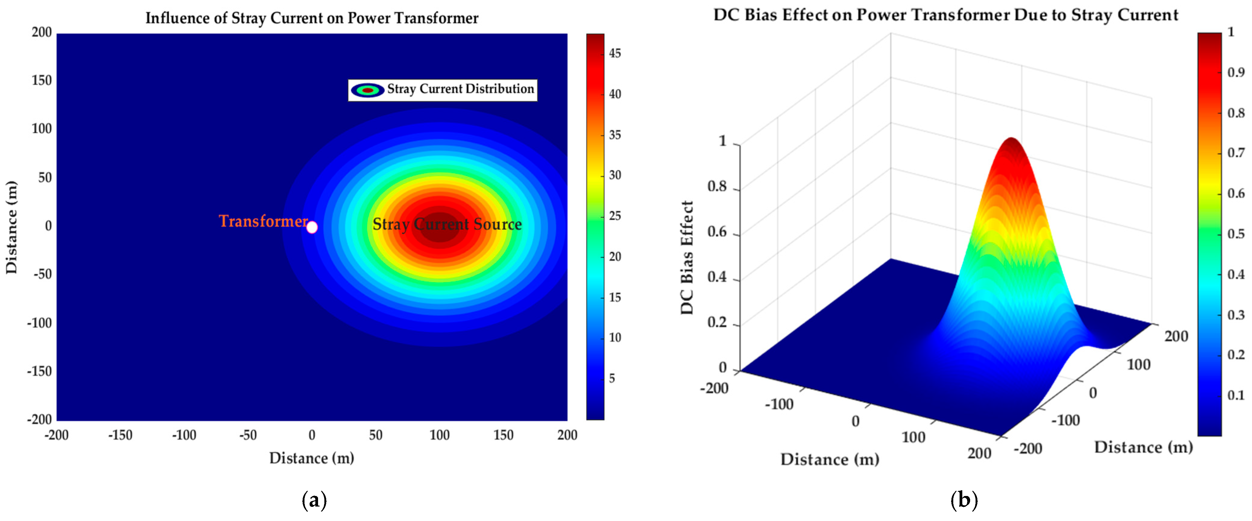
  • S (x, y) is the stray current distribution at the point (x, y);
  • IS is the stray current;
  • (xs, ys) is the position of the stray current source;
  • σ is the standard deviation, controlling the spread of the distribution.
Accordingly, the z-axis in the 3D plot represents the normalized DC bias effect derived from the 2D stray current distribution. Then, MATLAB code visualizes the influence of stray current on the utility transformer, as shown in Figure 6. Equations (5) and (6) are derived to show the influence of the stray current flow on the utility transformers near metros and capture how the stray current reduces with distance from the source, which is critical for understanding its impact on the utility transformer. The two plots strengthen and highlight the potential care of utility transformers near the DC TPSS. Figure 6a illustrates the spatial distribution of stray current around the utility transformer. With greater concentrations of current near the source, the contour plot illustrates how the strength of the stray current changes with distance from the source. This visualization helps to identify areas of special concern where the stray current could adversely affect the utility transformer, highlighting the need for monitoring and suppression strategies. Therefore, this scenario will ease the design of stray current mitigation and suppression measures of DC bias for high-risk areas in both the metro depot and the mainline [126]. Figure 6b signifies the DC bias effect, which is based on the stray current inputs to the transformer. The possible impact of stray current on the utility transformer’s operation is shown by the 3D surface plot, which graphically depicts how the DC bias changes across the vicinity of the transformer. Determining how much stray current may affect the transformer’s performance is possible because the surface height correlates with the normalized DC bias effect. In relevance to Equations (5) and (6), existing studies provide a statistical basis for the Gaussian distribution and apply empirical data on the stray current range (1–3 km) [32], link the rail potential to the transformer DC bias [108], and perform Monte Carlo optimization for DC bias risk [128]. Advanced studies would benefit from Gaussian decay empirically supported by soil anisotropy [110] and dynamic train loads [98]. Validations against the utility transformer damage (e.g., insulation breakdown [122]) data are necessary, in addition to the conceptual normalizations.
In general, the DC bias damages the utility transformer’s physical performance and threatens the reliability of the urban utility grid [128]. Therefore, exploring the specific impact of DC bias on a broader range of transformer types would provide a more wide-ranging understanding of the DC bias problem in power systems and investigation of the effects of DC bias on the other critical components, such as voltage transformers and transmission lines, is invaluable to understand the system-wide implications better. Therefore, what is generally underprovided is a systematic, methodical analysis of the exact scope of the DC bias problem, evaluation and experimental validation of the factors that determine the degree of DC bias, and effective and efficient measures for utility and metro systems that can eliminate the occurrence of the DC bias problem. If an urgent solution is not proposed, the far-reaching impacts of DC bias will become worse. As illustrated in Figure 7, the most valuable part is the DC bias research flow, which includes the DC bias modeling and analysis, utility transformer operation characteristic evaluation under DC bias situations, DC bias reduction strategies, and configuration scheme optimization. In Figure 7a, the MATLAB Simulink software helps establish the resistance network model for the power supply section of the metro system, simulates and analyzes the influence of resistance changes on the stray current distribution, and models the transformer, power system, etc. Although it is feasible for examining the impact of resistance changes on stray current distribution and is flexible for dynamic system simulation and the integration of electrical circuits with their controls, it is limited in handling complex 3D geometries or multi-physics interactions (e.g., interactions with soil resistivity). The CDEGS software helps analyze electrical system grounding, current distribution, electromagnetic fields, and related aspects. Compared to MATLAB Simulink, it can be applied to the simulation and analysis of stray current by modeling a three-dimensional finite element model of a subway tunnel, which includes a soil layer, structural reinforcement, drainage network, return rail, and feeder line [27,40]. The CDEGS assumes quasi-static conditions, making it less suitable for simulating time-varying stray currents caused by a dynamic train characterized by acceleration, deceleration, and varying traction loads. It also models soil as homogeneous or layered, thereby ignoring anisotropic soil resistivity and nonlinear grounding effects [27,28,29,40,86]. As the CDEGS focuses on grounding and stray current distribution, it lacks transformer electromagnetic models (e.g., core saturation and harmonics). Thus, it requires external tools to analyze the impacts of DC bias on transformer excitation current and grid stability [54]. The ANSYS helps study stray current interference from buried metals and explores the potential of pipeline metals to reach the ground and the nearby electric field. While robust for multi-physics applications (e.g., coupling electrical and thermal effects) [114], it is computationally intensive for large-scale metro–grid coupling models. The COMSOL Multiphysics includes the Galvanic Corrosion Module and helps to establish a finite element model of dynamic coupling between the subway and power grid systems. It validates the transformer vibration and noise studies under DC bias [57]. However, modeling large-scale metro networks (for instance, with a rail length exceeding 10 km and multiple substations) requires excessive computational resources due to fine meshing and multi-physics coupling, as it excels in localized, high-resolution simulations. Hybrid simulations that integrate with MATLAB or Python for co-simulation of metro dynamics and grid impacts can leverage these tools to create high-fidelity sub-models within broader hybrid frameworks. The PSCAD simulation helps model the transformer and the entire power system, and analyze the influence of DC bias on the transformer’s excitation current and the correlation between the neutral point current and the excitation current, leakage flux, and harmonics of the transformer [54,129]. As the PSCAD is limited to utility-side modeling, metro-side tools are required for integrated simulation. To summarize, this section explains the metro stray current causes DC bias in utility transformers, resulting in severe and far-reaching impacts, as well as transformer failures. The key factors include the proximity of substations to metro lines, soil resistivity, and dynamic train operations, with peak hours exacerbating the issue. The section also highlights modeling approaches and simulation tools for assessing DC bias risks, emphasizing the need for effective suppression strategies to safeguard transformer performance and maintain grid stability.

4. Suppression Measures for DC Bias

Recently, many studies have been conducted on DC bias suppression methods and engineering applications. Nowadays, the GIC data generated by geomagnetic storms against the utility grid are monitored, and protective devices, such as GIC-blocking capacitors and neutral grounding resistors, are implemented to limit the GIC flow [113]. There is ongoing research on DC bias suppression caused by HVDC and metro stray current. The transformer DC bias suppression method caused by metro stray current research can be considered from the utility side and the metro side. The primary current-mitigating measure on the metro side is the installation of drainage networks. Before the DC bias happens, prevention primarily involves mitigating stray current in nearby traction substations, i.e., using high insulating resistance between the rail and the ground (or the supporting structure), which must be the top priority. Appropriate provisions that should be made during the URT design and construction stages can help realize this [96]. Research has shown that the design and maintenance of metro grounding systems play a crucial role in mitigating stray current, which is the primary factor controlling the DC bias of utility transformers from their source [15,96]. Additionally, the grounding of the traction substation should be isolated from the grounding of the utility substation to suppress the intrusion of stray current into the utility transformer [39]. From the utility side, the primary measures are to install bias current suppression devices in utility transformers [9], install protection devices at neutral points during DC bias, and carefully monitor and take prompt action on the selected suppression measures. A transformer without a protection gap, either the capacitor or the limiting resistance at the grounding neutral point, exhibits significant noise [28]. Thus, installing DC magnetic bias suppression devices at the transformer’s neutral point can suppress the bias current from metro systems. There are four main categories of DC suppression: DC-blocking methods, DC-limiting methods, combined DC-limiting–DC-blocking methods, and reverse DC injection methods, as shown in Figure 8.

4.1. DC-Blocking Methods

The DC-blocking method involves the installation of capacitors in series with the neutral point, and a high-speed bypass is connected in parallel for quick switching, as shown in Figure 8a. During regular operation, the grounding switch (D1) is closed, and the switch D2 is also disconnected to ensure that the neutral point is effectively grounded. When the CT detects a direct current component that is more significant than the threshold at the neutral point and when the control and sensing system detects vibration, D1 is disconnected. The DC blocking is connected to the system by connecting the switch D2. When the neutral point of the utility transformer is connected to the ground, the DC cannot pass through the transformer windings at all. At the same time, when the DC bias occurs, the blocking capacitor operates in conjunction with the bypass device, opening the high-speed switch through supervisory control when the bias current exceeds the threshold. The bypass mainly protects the insulation of the transformer’s neutral point.
According to the study of the Shenzhen Power Grid Company, DC-blocking devices are found to be better in terms of grid safety and suppression effect [61]. However, it omits long-term maintenance (e.g., capacitor aging and bypass system inspections) and potential downtime during faults. While the DC blocking does not interfere with regular grid operation (unlike neutral point resistors), it requires a real-time DC sensor to trigger; sensor failure could delay the DC bias response, indicating a gap in mature consideration of determining elements. In the study of the DC bias phenomenon of the 220 kV utility transformer caused by Changsha Metro Lines 1 and 2, the capacitor DC-blocking device effectively suppressed the neutral DC and avoided the transformer from being affected by DC bias [26,50]. However, the study lacks post-installation monitoring data. The systematic cost–benefit comparison of other suppression alternatives is also necessary. The narrow focus on symptom mitigation and the lack of long-term performance data decreases the scalability of the device application and limit its robustness. As the metro running time is from 5:00 AM to midnight, most of the time, the utility substation faces the DC bias problem caused by the metro; therefore, the DC-blocking device adopts the constant capacitor mode in operation with the transformer neutral point [26]. In [44], it was recommended to use a neutral point series capacitor and the discharge gap, rectifier bridge, thyristor, and mechanical switch, which are connected in parallel to form a neutral point DC-blocking circuit, thereby avoiding any influence on the protection value of the transformer body. While the simulations are robust, the study lacks a field test post-installation, such as the actual capacitor performance under fault conditions or long-term DC fluctuations, which need to be considered. Furthermore, the discussion on how activation during faults affects zero-sequence protection settings is insufficient. With verification under maximum and minimum load conditions, to eliminate the DC posed by HVDC in the neutrals of the main transformers No. 1 and 2 at the Guohua Taishan power plant, it was determined that the blocking device will not affect the action behavior of relay protection, and effectively solves the problem of magnetic bias of the neutral point DC of the transformer after evaluating the protection settings in Guangdong’s 220 kV networks [130]. However, further evaluation is needed considering the metro conditions. It has been verified that the connection of the bias suppression capacitor does not affect the utility grid [74]. While deployable selectively at affected transformers, a cost–benefit analysis trade-off exists. With further research, for 220 kV utility substations, blocking devices with a reactance ≤ 1.2 Ω have been found to have little effect on the relay protection [128]. However, the failure rate analysis and maintenance costs are undermined by assuming ideal thyristor/discharge gap performance.
On the other hand, while installing these devices, the analysis and inspection of other utility transformers without DC-blocking devices are needed. When such a device is installed, the distribution of DC flowing via transformer windings in other utility substations and the ground will change. Suppositionally, if every transformer has a blocking device (BD) installed, the adverse effects of DC bias could be entirely removed. Nevertheless, the number of transformers with BDs is significantly lower than the total number of transformers in the entire AC system overall due to the significant budget required for big BDs. This situation is referred to as Finite DC BDs [37]. The DC BDs have relatively higher costs due to the installed bypass device and other elements, reaching approximately CNY 1.5 million [131]. The equipment cost of DC bias-blocking devices, as determined by studies on UHVDC-caused DC bias, amounts to CNY 6,750,000 [132]. Because of the considerable costs, their applicability is limited. In this instance, turning on the BD on a specific transformer may cause the DC flow to be redirected to other transformers lacking DC BDs, creating a new DC bias issue. For instance, blocking capacitors in the Pajiang 220 kV substation of the Guangdong power grid have significantly increased the neutral direct current of the other two adjacent substations [71]. Similarly, after the transformer of Shenzhen 500 kV substation was attached to a DC-blocking device, the DC at the neutral point decreased significantly, but the neutral point DC flow in the vicinity of it, at the 220 kV Jianlong and Shuibei substations, increased substantially, and the 220 kV Donghu and Qingshuihe substations increased as well, resulting in more serious DC bias of the transformers in the low-voltage networks [52]. In southwest China, for a 220 kV substation supplying the metro system, the total DC magnetic bias current of the utility substation was reduced by more than 15% upon the installation of DC-blocking devices [40]. However, DC bias current flows into other substations in the utility grid through the lightning protection wire, increasing the risk of DC bias in other substations, and the installation of a DC-blocking device in the 500 kV substation also led to an increase in the amplitude of the DC bias current of the main transformers of other multiple substations in the area. If the metro and utility sides do not take quick action, the issue may become too severe in areas with numerous utility substations, and an optimal device configuration is necessary to suppress DC bias more effectively [36].
A new circuit topology of a blocking DC capacitor with a controllable opening and broken bridge for suppressing DC bias has been proposed; compared with other capacitor suppression devices, it has the advantages of a simple control circuit, low cost, and small size [85]. While the study highlights the selection of capacitor and inductor parameters, it could benefit from a more detailed analysis of how these choices affect overall system performance under different operating conditions. The introduction of an inducive element may lead to resonance at specific frequencies, potentially causing oscillations that may affect system stability. Using a global optimization configuration method, a novel type of current balancing device (CBD) has been proposed for flexible suppression of the bias current. With these approaches, the high investment cost of the BDs can be optimized, and the influence of DC on other transformers without BDs can be taken into consideration [75]. However, a more detailed cost–benefit analysis is required to compare the long-term operational costs and maintenance of the proposed method with those of existing methods. Likewise, the scalability of the issue for larger networks or different configurations is not discussed; for instance, in the metro, considerations for dynamic conditions of trains and validations through field testing are necessary. Blocking the metallic flowing path between the metro system and the utility grid is suggested as more cost-effective than installing a DC-blocking device [38]. Nevertheless, the bypass control circuit complicates the method because it has several control modes and operation statuses. In the event of an asymmetric ground fault, the relay protection will be affected, and the influence of the capacitor on the relay protection behavior needs to be evaluated [51]. Additionally, the neutral point of the utility transformer may lose ground due to a capacitor failure [9]. Despite these drawbacks, this method of DC bias suppression is the conventional approach applied when the bias current exceeds the threshold, and most neutrally grounded transformers at the 220 kV voltage level in China are widely adopting it [37]. When installing suppression devices for DC bias in utility transformers caused by metro stray current, the blocking devices should be targeted for installation at the transformers supplying power to the metro first [128]. However, the metro train operation is dynamic; thus, its effect should be evaluated deeply. When selecting these methods, adjacent utility substations should be considered, especially in dense utility grid areas and cities with extensive metro networks, such as Shanghai, Shenzhen, Guangzhou, Beijing, Chengdu, Chongqing, Wuhan, and other major cities worldwide [7]. Explicitly, integrated planning is required during the construction of URT lines and utility substations to avoid mutual influence.

4.2. DC-Limiting Methods

The DC-limiting method involves resistors installed in series with the neutral point grounding with a gap in parallel for overvoltage protection, i.e., as shown in Figure 8b. Increasing the resistance between the neutral points of the utility transformers and the ground reduces the amount of DC that passes through the transformer windings without totally blocking it.
These devices were applied in the Guanxi, Gui-Guang HVDC system for the first time, reducing the neutral point current from 32.07 A to 4.63 A [106]. Similarly, 500 kV substations in Zhejiang province introduced these devices for utility main transformer noise suppression [73]. In the Baihetan–Zhejiang UHVDC transmission project, the current-limiting DC suppression device has an effective control to decrease the DC bias. After the suppression, the DC bias current of all stations was within the limits, reflecting the improvement of the scheme’s effectiveness with the DC bias [133]. However, factors such as installation costs, maintenance, and adaptability to different transformer types should also be considered. It was found that a single DC-limiting resistor was not practical in suppressing the bias current in adjacent substations, suggesting a series mixed DC-limiting resistor, which protects all substations nearby. Resistor values of 0.2 Ω and 0.8 Ω were investigated for 220 kV and 500 kV substations, respectively [31]. The method of using a neutral point series with small resistance was found to be more realistic when a large number of utility transformers were affected [134]. On the other hand, when a resistor with a resistance value of 8 Ω to 12 Ω is inserted in series at the neutral point of the transformer, the DC bias current can be effectively suppressed, and the attenuation degree of the current gradually decreases with the increase in resistance [72]. A better DC suppression effect was obtained in the 500 kV substation when a 3 Ω current-limiting resistor was installed at the neutral point of the transformer in Shanghai [53,134]. Even though the existing research provides the theoretical basis [31,72,134], a wide-ranging and practical validation of suitable values is necessary.
Installing such a device at one substation does not significantly impact the DC passing through transformer windings in other utility substations. This method has a simple structure, a better price (equipment costs reach CNY 5,720,000, according to UHVDC studies [132]), and a mature manufacturing and processing technology [106,131]. Despite the small resistance in series with the neutral point, it can effectively reduce the occurrence of abnormal vibration and sound in the transformer, the small resistance itself will affect the zero-sequence impedance of the system, and there is residual DC [9]. Additionally, if the resistor’s resistance value is too significant, it causes overvoltage, impacting the relay protection. The resistor installed in series with the neutral point at Chuncheng station changed the system parameters. It affected the relay protection of the transmission lines connected to the transformer [106]. After installation, the relay setting values must be recalculated; in practice, selecting the resistance value is another issue. With lower resistance, we cannot effectively reduce the bias current, and with higher values, the overvoltage problem will be incurred [70]. Moreover, this method does not thoroughly eliminate the bias current, but partially reduces it. Therefore, for efficient suppression, choosing a suitable resistance parameter for the device is necessary, and further research is needed to optimize the resistor value. These devices are generally used in transformers with low voltage levels. Future research should benefit from a longitudinal study to assess the durability and effectiveness of these suppression devices over time.

4.3. Combined DC-Limiting–DC-Blocking Method

This method (shown in Figure 8c) combines the resistor and the capacitor to suppress the DC bias current [135]. The series resistance is connected to the capacitor branch to absorb excessive energy from the capacitor. It is also equipped with a high-speed and reliable bypass protection system, which integrates the pros and cons of capacitance and resistance, making the structure more complex. Interestingly, the cost is better when compared to the two separate devices, reaching CNY 5,510,000 [132]. However, it needs an advanced system-level and cost–benefit analysis. Generally, its features are represented in Table 2.

4.4. Reverse DC Injection Method

This method involves the injection of a reverse direct current into the transformer neutral point from a controllable DC voltage source (DC generator), i.e., in the opposite direction to the current causing the DC bias. The reverse DC generator is connected in parallel to the grounding resistor of the neutral point and is grounded with a severe connection to an auxiliary earth electrode. The injected DC, “I” in Figure 8d, is a compensating current that counteracts the DC bias current. When the DC is injected, an opposing magnetic field to the DC bias will be generated; the net flux will be reduced, and the transformer will keep operating in its linear region, avoiding core saturation.
After a simulation test and field operation, the results of a study have shown that this method performed well in balancing transformer neutral point current caused by HVDC [68]. The method does not affect the existing relay, and it was installed at the Wunan 500 kV main transformer, reducing the DC bias current from 11 A to 2.2 A [136]. However, it cannot realize real-time dynamic compensation as the DC bias current varies from time to time, especially for metros. This method has a certain effect, and it can compensate for 80% of the DC magnetic biasing current [137]. However, the DC offset current required is large. Additionally, a closed-loop monitoring feedback system is necessary to monitor the neutral point DC in real time and provide the polarity and size of the compensation current according to the monitoring results [44]. Thus, careful control and adjustment are needed during the DC injection to match the bias current. It will not provide any benefit if the injected current is too high or too low; instead, it will lead to other issues, i.e., either increasing the bias or not having any suppressing effect. Hypothetically, there is no apparent difference between the suppression extent of the fully compensated reverse DC injection method and the blocking capacitance method; however, in practice, the current injection method is not common and is different in its operation. A novel reverse DC injection device has been proposed based on a high-frequency switching power supply [68]. With a Programmable Logic Controller (PLC) to monitor and control the system in HVDC, the suppression device has realized real-time monitoring and compensated the transformer neutral point. However, in the case of the metro, as the train’s operational state is dynamic, it needs an extra analysis. Therefore, advancing the online monitoring technology of the voltage can help determine the real-time bias current to be counteracted by the reverse DC generator.
This method suppresses the DC with a high current supply; considering that, as a small DC can already produce a significant vibration, a reverse DC injection to weaken the vibration of the transformer is not commonly applied [9]. Additionally, this method needs a grounding pole to connect with the DC generator, which is costly and requires massive construction. Like the DC-limiting devices, it also cannot eliminate the DC, but reduces it by part. The compensation effect is not good when multiple utility transformers are grounded at the neutral point and connected to different outgoing lines. Furthermore, the power consumption of the device is large, and the current injected into the ground grid increases the burden on the utility substation’s grounding [51]. Although the technique does not affect operating system parameters, the technology needed is somewhat sophisticated and high.
The reduction of the excitation current waveform distortion with DC bias current has been simulated after applying the DC-limiting, DC-blocking, and reverse DC compensation methods [138]. However, a specific effective method for practical applications has not been suggested. By comparing the three measures, i.e., the series resistance, the series capacitance, and the reverse current injection methods, the neutral point series capacitance method is proposed to solve the DC bias phenomenon of the transformer caused by stray current [51]. On the other hand, through the analysis of the pros and cons of the three measures, series resistance is found to be more advantageous, economical, and easier to adopt for its extensive application at the transformer’s neutral point [131]. Nevertheless, its overall performance needs further research. With the PSCAD simulation platform, the distortion rate of the hysteresis loop of 10 V DC in a 110 kV utility transformer is further reduced compared with the series resistor of 12 Ω; the suppression effect of DC bias is better when a capacitor of 0.7 Ω reactance is connected with the utility transformer’s neutral point [139]. However, it lacks real-world case studies to illustrate the practical implementation. By utilizing a Monte Carlo method, metro train operations are sampled, and an optimization model is developed for placing blocking devices (BDs) to minimize the number of installations for economic considerations while keeping the DC bias risk within acceptable levels [128]. However, challenges in comprehensively capturing the complex and dynamic nature of metro train operations and their impact on transformer DC bias may affect the generalizability and effectiveness of the proposed suppression strategy. The application of the potential compensation method in a 500 kV substation with a complex operating mode has greatly reduced the DC bias [71]; however, the challenge of measuring direct current on the series windings of autotransformers complicates the application. A particular analysis must be carried out with economic and effectiveness considerations to choose a method for practical projects. A summary of the comparisons of the various aspects of the existing suppression measures is provided in Table 2.
The other methods include the optimal design of the transformer’s internal structures [140]. The internal structure of the transformer has been modified by adding a compensation winding to cancel the magnetic flux generated by the biased DC in the core [77]. Moreover, as the air core reactance of the transformer under DC bias is supposed to increase, the excitation current’s distortion rate (effect) will decrease. Thus, increasing the air core reactance of the transformer can weaken the influence of the transformer’s DC bias to a certain extent [110]. The resistive load and inductive load on the low-voltage side of the UHV transformer are affected by DC bias, and the low-voltage side is the most affected by the DC bias when there is a capacitive load, which is mainly due to the resonance of some harmonics caused by DC bias due to the presence of the capacitance [141]. Therefore, designing the transformer parameters helps reduce the impact of the DC bias in utility transformers. The optimization of the metro system, including the rail-ground insulation and grounding design on the utility side, can also help reduce the magnitude of the stray current and, consequently, the DC bias in nearby transformers, and the timely monitoring of the change in neutral point current caused by the metro stray current is essential to take quick action [142]. The smaller the soil resistivity, the greater the amplitude of the stray current invading the utility system; as a result, the site selection of new utility substations should be in areas with large soil resistivity [39]. The standard [80] provides a guideline for DC magnetic bias suppression devices that can reduce the effects of DC bias in utility transformers influenced by HVDC; however, it does not address the complexities of DC bias issues related explicitly to metro systems.
Generally, as the metro system expands from a single line to multiple lines (revealing the geometric design of the metro lines’ complexity) [60,143,144], an interesting question arises: how does the metro network contribute to the neighboring infrastructure, including utility facilities, and what are its long-term and far-reaching implications? Providing that, this review article addresses the broad issue of DC bias caused by the metro, encompassing areas for future research by considering the actual operating environment of metro trains. Compared to international studies, more comprehensive research is needed on the DC magnetic bias suppression phenomenon in urban utility transformers, indicating the need for further investigation and standardization. Most importantly, the utility grid and URT authorities should strengthen their collaboration and jointly explore technical solutions and measures to reduce stray current leakage during the design and installation of utility grids and distribution networks. Thus, focusing on enhancing data collection methods to capture the diverse and dynamic operational scenarios of metro trains and incorporating more comprehensive modeling methods to improve the accuracy and applicability of the suppression strategy for transformer DC bias are necessary. The actual DC bias risk level and suppression are defined by the dynamic operation of metro trains, transformer characteristics, feasibility of installations, and costs, as well as operational scenarios that the metro networks are likely to adopt in the future or future changes anticipated in metro operations or urban utility grid configurations that could influence the selection of suppression measures.

5. Challenges and Future Directions

Research on the influence of stray current on utility transformer DC bias and its corresponding suppression measures is urgently needed, as most studies focus on DC bias caused by GIC and HVDC; the proposed suppression measures address DC bias resulting from these two factors. The stray current differs from these two factors in duration, predictability, and stability, and thus requires targeted attention. Hence, understanding the underlying mechanisms and employing appropriate mathematical modeling and simulation methods in suitable software for the metro, pipeline, and utility sides are promising to assess the potential overheating risks by considering several factors. These include the dynamic characteristics of the metro and the resistance at the metro side and pipeline side, and the utility side substation grounding resistance, which affect the value of the DC through the transformer neutral point, with an emphasis on transformer parameters’ change analysis. Thus, future research should focus on the following:
  • In-depth study of the possible coupling mechanism of stray current in the metro with the utility transformer and its specific DC bias influence on the transformer;
  • Developing the modeling and evaluation methods to predict and quantify the risk of utility transformer DC bias more accurately;
  • Implementation of advanced monitoring systems for assessing the real-time DC levels, facilitating timely interventions, and improving system safety;
  • Investigating more cost-effective solutions that maintain high reliability and performance;
  • Establishing a standardized criterion and optimizing transformer design to evaluate the effectiveness of future suppression technologies.

6. Conclusions

By analyzing several research studies on utility transformer DC bias caused by stray current in the metro, it is found that the current research primarily focuses on theoretical analysis, simulation, and practical measurement. The theoretical analysis focuses on the causes of stray current, influencing mechanisms, and its interference with the utility transformer. The simulations analyze the specific influence of stray current on the DC bias of the transformer by establishing a model. In practice, despite their inadequacy, the results of theoretical analysis and simulation are verified by experiments. These studies show that stray current in the metro has a DC bias effect on nearby neutral point grounded utility transformers. This effect is particularly significant within certain ranges along the metro line. With appropriate modeling and simulation, future research may find that more feasible and widely applicable suppression measures should undergo field applications and pioneering projects to validate the proposed solutions. Developing and evaluating effective mitigation strategies for stray current and suppression measures to address DC bias in transformers, and providing recommendations for power system operators and engineers to ensure transformers’ reliable and accurate operation, are valuable for environmental safety and operational sustainability.

Author Contributions

Conceptualization, A.M. and X.Y.; methodology, A.M. and X.Y.; software, A.M.; validation, X.Y., X.S., T.W. and L.C.; formal analysis, A.M., X.Y., K.L., T.W. and L.C.; investigation, X.Y., X.S., K.L. and L.C.; resources, A.M.; data curation, X.Y., X.S., K.L. and T.W.; writing—original draft preparation, A.M.; writing—review and editing, A.M., X.Y., X.S., K.L., T.W. and L.C.; visualization, A.M.; supervision, X.Y. All authors have read and agreed to the published version of the manuscript.

Funding

This research received no external funding.

Data Availability Statement

The original contributions presented in the study are included in the article; further inquiries can be directed to the corresponding author.

Conflicts of Interest

Authors Tianyi Wu and Lu Chen were employed by the State Grid Shanghai Electric Power Research Institute. The remaining authors declare that the research was conducted in the absence of any commercial or financial relationships that could be construed as a potential conflict of interest.

References

  1. Ma, Y.; Bhatt, N.R.; Wu, Q.; Pokharel, M. Urban rail transit in heritage-rich cities: Exploring the unique project risks. Eng. Constr. Archit. Manag. 2025. [Google Scholar] [CrossRef]
  2. Wei, Y.; Yang, X.; Xiao, X.; Ma, Z.; Zhu, T.; Dou, F.; Wu, J.; Chen, A.; Gao, Z. Understanding the Resilience of Urban Rail Transit: Concepts, Reviews, and Trends. Engineering 2024, 41, 7–18. [Google Scholar] [CrossRef]
  3. Xue, X.; Zhang, Y.; Zhang, L.; Wang, Y.; Hou, R.; Ni, T. Evaluation on Sustainable Development of Smart Urban Rail Transit. Mob. Inf. Syst. 2022, 2022, 1–10. [Google Scholar] [CrossRef]
  4. Cao, Y.; Xiao, S.; Yan, J.; Liu, C.; Li, T.; Liu, X.; Wu, G.; Guo, Y.; Hou, J.; He, Y.; et al. Contribution analysis of neutral current for the substations invaded by stray current from multiple metro lines. Int. J. Electr. Power Energy Syst. 2025, 169, 110773. [Google Scholar] [CrossRef]
  5. Cao, Z. Integrating Station-Area Development with Rail Transit Networks: Lessons from Japan Railway in Tokyo. Urban Rail Transit 2022, 8, 167–174. [Google Scholar] [CrossRef]
  6. Dodds, R. A case study from a utility [DC traction stray current control]. In Proceedings of the IEE Seminar on DC Traction Stray Current Control—Offer a Stray a Good Ohm, London, UK, 21 October 1999. [Google Scholar]
  7. Lu, K.; Zhang, L.; Li, S.; Huang, Y.; Ding, X.; Hao, J.; Huang, S.; Li, X.; Lu, F.; Zhang, H. Urban Rail Transit in China: Progress Report and Analysis (2015–2023). Urban Rail Transit 2024, 1–27. [Google Scholar] [CrossRef]
  8. Chen, Y.; Li, Z.; Dong, W.; Zhao, H.; Ye, S. Influences of Rail Transit Station on Temporal-spatial Distribution Patterns of Surrounding Service Industry: Fuzhou Metro Line 1 Case. J. Subtrop. Resour. Environ. 2021, 16, 77–88. [Google Scholar]
  9. Lin, J.; Zheng, Y.; Yang, Z.; Zhan, J.; Jin, L.; Li, C. Influence of Metro Stray Current on Transformer Operation in Zhejiang Power Grid and the Control Measures. Zhejiang Electr. Power 2021, 40, 6. [Google Scholar]
  10. Wang, C.; Li, W.; Wang, Y.; Xu, S.; Fan, M. Stray Current Distributing Model in the Subway System: A review and outlook. Int. J. Electrochem. Sci. 2018, 13, 1700–1727. [Google Scholar] [CrossRef]
  11. Bhagat, S.; Yang, X.; Wang, M.; Mariscotti, A. Review and Evaluation of Stray Current Mitigation for Urban Rail Transit. Trans. China Electrotech. Soc. 2021, 36, 4851–4863. [Google Scholar]
  12. Wang, C.; Qin, G. Corrosion of underground infrastructures under metro-induced stray current: A review. Corros. Commun. 2024, 14, 23–38. [Google Scholar] [CrossRef]
  13. Aatif, S.; Hu, H.; Rafiq, F.; He, Z. Analysis of rail potential and stray current in MVDC railway electrification system. Railw. Eng. Sci. 2021, 29, 394–407. [Google Scholar] [CrossRef]
  14. Zaboli, A.; Vahidi, B. Stray Current and Rail Potential Control Strategies in Electric Railway Systems. In Transportation Electrification: Breakthroughs in Electrified Vehicles, Aircraft, Rolling Stock, and Watercraft; Wiley: Hoboken, NJ, USA, 2022; pp. 299–323. [Google Scholar]
  15. Wang, C.; Wang, Y.; Xu, S.; Li, W.; Wang, Y.; Xing, F. Assessment of interference scope induced by stray current in the metro depot for the corrosion risk of buried metal pipeline. Electr. Eng. 2024, 106, 4277–4296. [Google Scholar] [CrossRef]
  16. George, M.; Ian, C. Earthing and Negative Return Systems in the Melbourne DC Railway. In Proceedings of the Down to Earth Conference (DTEC), Melbourne, Australia, 27–28 November 2018. [Google Scholar]
  17. Yang, X.; Wang, M.; Zheng, T.Q.; Sun, X. Modelling and Simulation of Stray Current in Urban Rail Transit—A Review. Urban Rail Transit 2024, 10, 189–199. [Google Scholar] [CrossRef]
  18. Gu, J.; Yang, X.; Zheng, T.Q.; Xia, X.; Zhao, Z.; Chen, M. Rail Potential and Stray Current Mitigation for Urban Rail Transit With Multiple Trains Under Multiple Conditions. IEEE Trans. Transp. Electrif. 2022, 8, 1684–1694. [Google Scholar] [CrossRef]
  19. Liang, H.; Wu, Y.; Han, B.; Lin, N.; Wang, J.; Zhang, Z.; Guo, Y. Corrosion of Buried Pipelines by Stray Current in Electrified Railways: Mechanism, Influencing Factors, and Protection. Appl. Sci. 2024, 15, 264. [Google Scholar] [CrossRef]
  20. Lin, S.; Zhang, J.; Liu, X.; Zhang, X.; Cai, Z.; Chen, X.; Mei, Y. Study on Distribution Characteristics of Metro Stray Current and Evaluation of Cumulative Corrosion Effect. Adv. Civ. Eng. 2022, 2022, 6845847. [Google Scholar] [CrossRef]
  21. Cai, Z.; Zhang, X.; Cheng, H. Evaluation of DC-Subway Stray Current Corrosion With Integrated Multi-Physical Modeling and Electrochemical Analysis. IEEE Access 2019, 7, 168404–168411. [Google Scholar] [CrossRef]
  22. Paul, D. DC Stray Current in Rail Transit Systems and Cathodic Protection [History]. IEEE Ind. Appl. Mag. 2016, 22, 8–13. [Google Scholar] [CrossRef]
  23. Memon, S.A.; Fromme, P. Stray Current Corrosion and Mitigation: A synopsis of the technical methods used in dc transit systems. IEEE Electrif. Mag. 2014, 2, 22–31. [Google Scholar] [CrossRef]
  24. Wang, Y.; Huang, Y.; Peng, C.; Li, W.; Wang, C. Evaluation model for dynamic interference of subway stray current based on surface potential gradient. J. Beijing Jiaotong Univ. 2020, 44, 30. [Google Scholar]
  25. Zhou, H.; Zhang, J.; Li, J.; Wei, T. Simulation Analysis of Interference of Subway Stray Current on Buried Metals. J. East China Jiaotong University 2022, 39, 1–9. [Google Scholar]
  26. Liu, W.; Zhou, W.; Ye, H.; Peng, P.; Wu, X. Research on influence and control measures of metro rail in Changsha. Hunan Electr. Power Mag. 2017, 1, 7–9. [Google Scholar]
  27. Yu, K.; Ni, Y.; Zeng, X.; Peng, P.; Fan, X.; Leng, Y. Modeling and Analysis of Transformer DC Bias Current Caused by Metro Stray Current. IEEJ Trans. Electr. Electron. Eng. 2020, 15, 1507–1519. [Google Scholar] [CrossRef]
  28. Zhang, B.; Yu, L.B.; Li, H.; Tang, H.; Zhang, D.Q.; Jiang, D.W. Influence and Analysis of Urban Subway on DC Bias of Power Transformer. In Proceedings of the 6th Asia Conference on Power and Electrical Engineering (ACPEE), Chongqing, China, 8–11 April 2021. [Google Scholar]
  29. Peng, P.; Zeng, X.-J.; Ni, Y.-R.; Yu, K.; Leng, Y.; Zhou, W.-H.; Xie, Y.-H. Modeling for the DC bias current of transformer caused by the metro stray current. J. Electr. Power Sci. Technol. 2021, 36, 192–198. [Google Scholar]
  30. Wang, A.; Lin, S.; Hu, Z.; Li, J.; Wang, F.; Wu, G.; He, Z. Evaluation Model of DC Current Distribution in AC Power Systems Caused by Stray Current of DC Metro Systems. IEEE Trans. Power Deliv. 2021, 36, 114–123. [Google Scholar] [CrossRef]
  31. Chen, L.; Ni, H.; Zeng, J.; Du, Q.; Guo, Y. Protection Scheme of Urban Power Grid Against Stray Currents in Metro. In Proceedings of the 2023 Panda Forum on Power and Energy (PandaFPE), Chengdu, China, 27–30 April 2023; pp. 1573–1579. [Google Scholar]
  32. Chen, L.; Wu, J.-L.; Huang, H.; Wang, Z.-Z.; Wu, T.-Y.; Su, L. Study on Transformer Magnetic Bias Caused by Metro Stray Current in Shanghai Power Grid. Transformer 2023. [Google Scholar] [CrossRef]
  33. Wang, A.; Lin, S.; He, Z.; Zhang, J.; Wu, G. Probabilistic Evaluation Method of Transformer Neutral Direct Current Distribution in Urban Power Grid Caused by DC Metro Stray Current. IEEE Trans. Power Deliv. 2023, 38, 541–552. [Google Scholar] [CrossRef]
  34. Wu, Y.; Hu, S.; Cai, H. Analysis and Simulation of Time-Frequency Characteristics of Dynamic DC Bias Current in Urban Power Grids caused by Metro Stray Current. In Proceedings of the 2024 IEEE 7th International Electrical and Energy Conference (CIEEC), Harbin, China, 10–12 May 2024; pp. 660–664. [Google Scholar]
  35. Zhou, Z.; Yan, Y.; Yu, Y.; Zeng, X.; Ni, Y.; Cheng, X.; Yu, K.; Tang, Y. Analysis of the influence of metro stray current on transformer DC bias. J. Electr. Power Sci. Technol. 2024, 39, 134–143. [Google Scholar]
  36. Liu, C.; Ganebo, Y.S.; Wang, D. Optimal configuration method of capacitor isolation device against DC bias on improved niche GA algorithm. J. Eng. 2018, 2019, 1571–1574. [Google Scholar] [CrossRef]
  37. Xie, Z.; Lin, X.; Zhang, Z.; Li, Z.; Xiong, W.; Hu, H.; Khalid, M.S.; Adio, O.S. Advanced DC Bias Suppression Strategy based on Finite DC Blocking Devices. IEEE Trans. Power Deliv. 2017, 32, 2500–2509. [Google Scholar] [CrossRef]
  38. Xiao, L.; Zhang, J.; Chen, L.; Wu, G.; Zhang, F.; Lai, Z.; Xu, H. Analysis on the DC Magnetic Bias Characteristic of Transformer in Power System Caused by the Subway Stray Current. South. Power Syst. Technol. 2021, 15, 129–134. [Google Scholar]
  39. Wei, R.; Liu, J.; Gao, H.; Chen, T.; Yan, Q.; Kong, W. Study on the Effect of the Metal Path on the Distribution of Metro Stray Currents in the Power Grid. J. Electr. Eng. 2023, 18, 90–98. [Google Scholar]
  40. Li, X.; Zhang, H.; Wu, J.; Zhou, W. Research on Influence of Installation Position of DC Blocking Devices on DC Magnetic Bias Current Distribution of Main Transformer in Power Grid. Sichuan Electr. Power Technol. 2023, 46, 1–6. [Google Scholar]
  41. Shi, M.; Wu, B.; Jin, Y.; Qiu, A.; Li, J. Research Summary on the Impacts of DC Magnetic Bias on Transformer. High Volt. Appar. 2018, 54, 20–36. [Google Scholar]
  42. Zhang, L.; Mao, C.; Sun, L.; Han, Y.-H.; Han, Q. Review of Research Status on DC Magnetic Bias of Transformers. Electr. Eng. 2019, 8, 1–6. [Google Scholar]
  43. Yi, Q.; Lin, Y.-H.; Liang, J.-H.; Chen, S.-Y.; Huang, Z. Influence of Metro Ground Current on Tianguang DC. Electr. Technol. 2020, 10, 3. [Google Scholar]
  44. Li, J. Analysis and Countermeasure of DC Bias Influence of Main Transformer in Power Plant. Inn. Mong. Electr. Power Technol. 2021. [Google Scholar] [CrossRef]
  45. Li, X.; Chu, F.; Shi, S. Influence of Rail Transit on Neutral Current and Vibration of 220kV Substation Along the Line. Trans. China Electrotech Soc. 2021, 36, 423–429. [Google Scholar]
  46. Shen, X.; Xie, J.; Fu, B.; Yin, Z. Influence and Analysis of DC Bias on Excitation Characteristic and Reactive Power of Main Transformer in Power Plant. Energy Res. Manag. 2017, 2, 70–74. [Google Scholar]
  47. Wen, X.; Guo, T.; He, Z.; Yang, Q.; Lu, H. Review on the Related Problems of DC Magnetic Bias. High Volt. Appar. 2016, 52, 1–8. [Google Scholar]
  48. Tang, M.; Guo, Y.; Xiao, S.; Zeng, J.; Zhong, H.; Ruan, L.; Tang, Z.; Wu, G. Evaluation of the impact of urban rail system on the distribution of DC currents in the power grid considering multi-train density. Electr Pow. Syst. Res. 2024, 236, 110571. [Google Scholar] [CrossRef]
  49. Zhang, L.; Bao, J.; Li, X.; Chen, L. Factors of stray current in rail transit affecting DC magnetic bias of AC power grid transformer. J. Electr. Power Sci. Technol. 2024, 39, 79–91. [Google Scholar]
  50. Peng, P.; Zhou, W.-H.; Xie, Y.-H.; Liu, Y.; Wu, X.-W.; Mao, W.-Q. Analysis and Research on DC Bias of Transformer Caused by Metro Stray Current. Transformer 2017, 54, 26–30. [Google Scholar]
  51. Peng, J. Study on the Influence of Metro Stray Current on Urban Power Grid Transformer and Its Solution. Shenhua Technol. 2018, 5, 53–56. [Google Scholar]
  52. Wu, G.; Chen, L.; Shi, Y.; Lin, S. Analysis on Test and Suppression of DC Bias of 500 kV Main Transformer in Shenzhen Substation. Power 2020, 33, 118–124. [Google Scholar]
  53. Huang, H.; Chen, L.; Wu, T.; Fu, C.; Bao, J.; Li, X. Influence of Dynamic Operation of Urban Rail Transit on DC Magnetic Bias of AC Power Grid Transformer. Power Syst. Technol. 2022, 46, 4524–4533. [Google Scholar]
  54. Yi, Q.; Yan, F.; Lin, Y.-H.; Chen, S.-Y.; Liang, J.-h. Simulation Analysis and Research on DC Bias of Transformer Neutral Point Caused by Guangzhou Metro. Transformer 2020, 57, 41–46. [Google Scholar]
  55. Chen, Z.; Li, H.; Liu, L.; Xiang, L.; Bai, B. DC Bias Treatment of Hybrid Type Transformer Based on Magnetic Flux Modulation Mechanism. IEEE Trans. Magn. 2019, 55, 1–4. [Google Scholar] [CrossRef]
  56. Ning, X.; Gao, G.; Yin, C.; Xiao, S.; Yang, F.; Guo, Y.; Zhang, X. Characteristics of Transformer Bias Current Caused by Metro. Metrop. Rapid Transit 2023, 5, 125–131. [Google Scholar] [CrossRef]
  57. Li, Y.; Luo, R.; Tan, F.; Huang, J.; Wu, J.; Chen, X.; Fang, M. Analysis and research on DC bias of transformer caused by subway stray current. J. Shanghai Dianji Univ. 2019, 22, 56–62. [Google Scholar]
  58. Wu, G.X.; Gong, J.Q.; Wang, Q.L.; Zheng, R.L.; Wang, G.L.; Liu, Y.N. Analysis of the Influence of DC Magnetic Bias Induced by Rail Transit Stray Current on Harmonic Characteristics of Transformer Neutral Current. In Proceedings of the 2022 IEEE/IAS Industrial and Commercial Power System Asia (I&CPS Asia), Shanghai, China, 8–11 July 2022; pp. 1918–1923. [Google Scholar]
  59. Lin, S.; Tang, Z.; Chen, X.; Liu, X.; Liu, Y. Analysis of Stray Current Leakage in Subway Traction Power Supply System Based on Field-Circuit Coupling. Energies 2024, 17, 3121. [Google Scholar] [CrossRef]
  60. Li, C.; Du, Q.; Guo, Y.; Liu, Y.; Yang, F.; Chen, L.; Zhang, X.; Huang, G.; Gao, G.; Wu, G. Modeling of Stray Currents From Metro Intruding Into Power System Considering the Complex Geological Conditions in Modern Megacities. IEEE Trans. Transp. Electrif. 2023, 9, 1653–1663. [Google Scholar] [CrossRef]
  61. Zhang, B.; Huang, W.; Chen, X. Probe into Impacts of DC Magnetic Bias on Main Transformer in Shenzhen Power Grid. Shaanxi Electr. Power 2014, 42, 69–72. [Google Scholar]
  62. Wang, A.; Lin, S.; Wu, G.; Li, X.; Wang, T. Characteristic Extraction and Assessment Methods for Transformers DC Bias Caused by Metro Stray Currents. Entropy 2024, 26, 595. [Google Scholar] [CrossRef] [PubMed]
  63. Liu, M.; Fu, J.; Wang, X. Spectral Analysis on Vibration Signal Caused by DC Magnetic Bias of Transformer. J. State Grid Technol. Coll. 2018, 21, 26–29. [Google Scholar]
  64. Wu, X.; Zhou, N.; Hu, S.; Peng, J.; Lu, L. Audible noise and vibration characteristics of DC-bias in power transformers caused by urban mass transit system. Electr. Meas. Instrum. 2017, 54, 117–122. [Google Scholar]
  65. Huang, H.; Chen, L.; Wu, T.; Fu, C.; Xin, Q.; Zhang, L. Urban rail transit stray current on 500kV transformers along the line Test analysis of dc magnetic bias effect. In Proceedings of the 2022 IEEE 5th International Electrical and Energy Conference (CIEEC), Nanjing, China, 27–29 May 2022; pp. 4198–4204. [Google Scholar]
  66. Zhu, J.; Mao, C.; Wang, Z.; Chen, J.; Wang, D.; Luan, L.; Qiao, Y.; Wang, H. A Novel Suppression Method for Grounding Transformer Against Earth Current From Urban Rail Transit. IEEE Trans. Ind. Electron 2021, 68, 11651–11662. [Google Scholar] [CrossRef]
  67. Cheng, X.; Yu, K.; Zeng, X.; Ni, Y.; Tang, Y.; Han, W. Restraining Method of Transformer DC Bias Caused by Metro Stray Currents. Power Syst. Technol. 2024, 48, 1700–1710. [Google Scholar]
  68. Wang, X.; Mei, G.; Xie, Y. Research and application of reverse injection DC-balancing device based on high-frequency switching power supply. Power Syst. Prot. Control. 2015, 43, 139–144. [Google Scholar]
  69. Chen, D.; Hou, B.; Feng, Z.; Bai, B. Study of Magnetostriction Influence of Electrical Sheet Steel Under Different DC Biases. IEEE Trans. Magn. 2019, 55, 1–5. [Google Scholar] [CrossRef]
  70. Xie, Z.; Ling, X.; Li, Z.; Zheng, Y.; Guo, Q.; Xiong, W.; Bo, Z. Flexible Suppression Scheme for DC Bias Based on Adjustable Parallel Resistance. Proc. CSEE 2017, 37, 5862–5872. [Google Scholar]
  71. Pan, Z.; Wang, X.; Tan, B.; Zhu, L.; Liu, Y.; Liu, Y.; Wen, X. Potential Compensation Method for Restraining the DC Bias of Transformers During HVDC Monopolar Operation. IEEE Trans. Power Deliv. 2016, 31, 103–111. [Google Scholar] [CrossRef]
  72. Qiu, Q.; Wu, G.-N.; Ren, Z.-C.; Zhang, Y.-K. Transformer Neutral Series Low Resistance Designed against DC Magnetic Bias. East China Electr. Power 2012, 40, 0812–0816. [Google Scholar]
  73. Shen, T.; Sun, X.-G.; Dai, J.-G.; Lan, Y.-J. Analysis of Abnormal Main Transformer Noise and Its Treatment Measures in 500kV substation. Transformer 2013, 50, 68–71. [Google Scholar]
  74. Hu, Y. Influence and Control of Urban Rail Transit on Urban Power Grid. Build. Mater. Technol. Appl. 2019, 38–41. [Google Scholar] [CrossRef]
  75. Ma, S.; Lin, X.; Li, Z.; Jin, N.; Rong, Z.; Zhang, P.; Xu, H. A Novel DC Bias Suppression Method Considering the Cooperation of Multiple Devices. IEEE Access 2021, 9, 130212–130220. [Google Scholar] [CrossRef]
  76. Yan, K.; Mu, Y.; Xu, Q.; Wang, H.; Yang, J.; Mu, S. Analysis of Noise Anomalies of a 220 kV Transformer in Operation and Verification with Simulation. Maint. Technol. 2021, 23, 60–65. [Google Scholar]
  77. Zhang, J.; Pan, Y.; Ma, K.; Peng, X.-T.; Huang, D.-J. A New Method of Restraining DC Bias of Power Transformer. Electr. Eng. 2021, 26–29. [Google Scholar]
  78. Liu, M.; Xu, Z.; Qin, R. DC Magnetic Bias Control and Test Analysis of Power Transformer. Yunnan Electr. Power 2024, 52, 8–11. [Google Scholar]
  79. Khaparde, S.A. Transformer Engineering Design, Technology, and Diagnostics; CRC Press: Boca Raton, FL, USA, 2012. [Google Scholar]
  80. IEC TS 60076-23; DC Magnetic Bias Suppression Devices. IEC: Geneva, Switzerland, 2018.
  81. Kang, H.; Li, Y.; Wang, Y. Dynamic distribution characteristic of urban rail transit stray current under different traction conditions with multiple additional resistance. J. Beijing Jiaotong Univ. 2022, 46, 167–174. [Google Scholar]
  82. Hong, Z.; Zhao, W.; Tan, N.; Gu, C.; Tong, X. A Method for Locating Insulation Damage Points on Rail Transit Based on Ground Potential and Chan Algorithm. J. Shanghai Univ. Electr. Power 2024, 40, 51–58. [Google Scholar]
  83. Yang, G.; Ma, X.; Cao, Z. Modeling and dynamic analysis of uneven parameter metro stray current distribution. Electr. Eng. 2023, 106, 2021–2032. [Google Scholar] [CrossRef]
  84. Abda, Z.M.K.; Aziz, N.F.A.; Kadir, M.Z.A.A.; Rhazali, Z.A. A Review of Geomagnetically Induced Current Effects on Electrical Power System: Principles and Theory. IEEE Access 2020, 8, 200237–200258. [Google Scholar] [CrossRef]
  85. Wang, Z.; Tong, X.; Qi, W. Blocking DC Capacitor Controllable Opening and Broken Bridge Suppression in Transformer DC Magnetic Bias. Trans. China Electrotech. Soc. 2013, 28, 120–126. [Google Scholar]
  86. Gao, H.; Wei, R.; Liu, J.; Chen, T.; Yang, L.; Yan, Q.; Kong, W. Study on the Mechanism of Magnetic Coupling Influence of Urban Rail Transit on Power Transformers. Railw. Stand. Des. 2024, 70, 1–8. [Google Scholar] [CrossRef]
  87. Park, J.; Kang, D. Evaluation of long-term durability of heat-shielding coatings against railway environmental deterioration conditions. Korean Soc. Nondestruct. Test. 2022, 42, 43–50. [Google Scholar] [CrossRef]
  88. Pires, C.L. What the IEC Tells Us About Stray Currents: Guidance for a Practical Approach. IEEE Electrif. Mag. 2016, 4, 23–29. [Google Scholar] [CrossRef]
  89. Wu, Y.; Cai, H.; Hu, S.; Zhang, Y. Factors Influencing the Stray Current and Surface Potential in Metro Traction System. Insul. Surge Arrester 2024, 70–76+84. [Google Scholar] [CrossRef]
  90. CJJT49-2020; Technical Standard for Corrosion Protection of Stray Current in Metro. Ministry of Housing and Urban-Rural Development: Beijing, China, 2020.
  91. Wu, Y.; Cai, H. Research on the DC Bias in AC Power Grid Caused by Metro Stray Current. In Proceedings of the 2023 IEEE 4th International Conference on Electrical Materials and Power Equipment (ICEMPE), Shanghai, China, 7–10 May 2023; pp. 1–9. [Google Scholar]
  92. Zhou, Q.; Lin, S.; Zhang, W. Analysis and Mitigation of Stray Current in Modern Metro Systems With OVPD and PSD. IEEE Trans. Transp. Electrif. 2024, 10, 3153–3166. [Google Scholar] [CrossRef]
  93. Zhou, J.; Chen, Q.; Li, L. Protective Measures of Subway Stray Current in Steel Gas Pipeline. Gas Heat 2018, 38, 1–4. [Google Scholar] [CrossRef]
  94. Sun, X.; Yang, X.; Zhao, R.; Wang, Z.; Chen, M.; Zheng, T.Q. S-Transform Based Time–Frequency Evaluation of Dynamic Stray Current in Zero-Resistance Converter System. Energies 2025, 18, 1594. [Google Scholar] [CrossRef]
  95. EN 50162-2005; Protection Against Corrosion by Stray Current from Direct Current Systems. CENELEC: Brussels, Belgium, 2005.
  96. Vranesic, K.; Bhagat, S.; Mariscotti, A.; Vail, R. Measures and Prescriptions to Reduce Stray Current in the Design of New Track Corridors. Energies 2023, 16, 6252. [Google Scholar] [CrossRef]
  97. Du, G.; Wang, J.; Jiang, X.; Zhang, D.; Yang, L.; Hu, Y. Evaluation of Rail Potential and Stray Current With Dynamic Traction Networks in Multitrain Subway Systems. IEEE Trans. Transp. Electrif. 2020, 6, 784–796. [Google Scholar] [CrossRef]
  98. Lin, S.; Wang, A.; Liu, M.; Lin, X.; Zhou, Q.; Zhao, L. A Multiple Section Model of Stray Current of DC Metro Systems. IEEE Trans. Power Deliv. 2021, 36, 1582–1593. [Google Scholar] [CrossRef]
  99. Peng, X.; Huang, Z.; Chen, B.; Liu, D.; Li, H. On the interference mechanism of stray current generated by DC tram on pipeline corrosion. Eng. Fail. Anal. 2020, 116, 104760. [Google Scholar] [CrossRef]
  100. Peng, P.; Zeng, X.; Leng, Y.; Yu, K.; Ni, Y. A New On-line Monitoring Method for Stray Current ofDCMetro System. IEEJ Trans. Electr. Electron. Eng. 2020, 15, 1482–1492. [Google Scholar] [CrossRef]
  101. Wang, H.-J.; Mo, W.-X.; Qiao, Y.-J.; Luan, L.; Xu, Z. Study on Characteristics of Earth Current Distribution in Tractive Power Supply System. Transformer 2019, 56, 19–24. [Google Scholar]
  102. Akbari, M.; Rezaei-Zare, A. Thermal Analysis of Power Transformers Under Geomagnetically Induced Current. IEEE Trans. Power Deliv. 2023, 38, 4114–4121. [Google Scholar] [CrossRef]
  103. Bu, Q.; Wen, H.; Zhu, Y.; Shi, H.; Chu, G. Transient Bias Suppression Optimization for Bidirectional 2/3-Level DC-DC Converters. In Proceedings of the 2022 International Power Electronics Conference (IPEC-Himeji 2022-ECCE Asia), Himeji, Japan, 15–19 May 2022; pp. 2647–2652. [Google Scholar]
  104. Ni, Y.; Yu, K.; Zeng, X.; Leng, Y.; Peng, P.; Zhou, W.-H.; Xie, Y.-H. A correlation analysis on transformer DC bias current caused by metro stray current. J. Electr. Power Sci. Technol. 2021, 36, 136–143. [Google Scholar]
  105. Liu, W.; Li, S.; Tang, Y.; Ma, Q.; Zhou, L. Train-earth-grid coupling DC magnetic bias model for stray current diffusion. Int. J. Electr. Power Energy Syst. 2024, 158, 109962. [Google Scholar] [CrossRef]
  106. Niu, B.; Zeng, R.; Zhang, B.; He, J. Research and Design of the Neutral Series Resistor to Restrain the HVDC Ground Current Flowing into Transformer. In Proceedings of the 2006 International Conference on Power System Technology, Chongqing, China, 22–26 October 2006. [Google Scholar]
  107. Wu, Y.; Cai, H.; Hu, S.; Zhang, Y. Time Domain Simulation of the Influence of Metro Traction System on Ground Potential. South. Power System Technol. 2023, 17, 80–89. [Google Scholar]
  108. Wang, A.; Lin, S.; Wu, J.; Zhang, H.; Li, J.; Wu, G.; He, Z. Relationship Analysis Between Metro Rail Potential and Neutral Direct Current of Nearby Transformers. IEEE Trans. Transp. Electrif. 2021, 7, 1795–1804. [Google Scholar] [CrossRef]
  109. Mu, Y.; Yan, K.; Yue, G.; Miao, L.; Wu, W.; Liu, Y.; Xi, T. Key influencing factors of subway stray current geoelectric field. J. Xian Univ. Sci. Technol. 2021, 41, 1122–1129. [Google Scholar]
  110. Shi, Y.; Zhao, L.; Lin, S.; Ren, Y.; Wang, A.; Wu, G. Analysis of Distribution of Metro Stray Current in Urban Power Grid and Its Influencing Factors. Power Syst. Technol. 2021, 45, 1951–1957. [Google Scholar]
  111. Wang, W.; Li, W. Topology of Power Grid and Characteristics of Stray Current Distribution in Metro Systems. Metrop. Rapid Transit 2023, 5, 110–116. [Google Scholar] [CrossRef]
  112. Syafruddin, H.; Soib, T.; Risnidar, C.; Siti, R.M. Effect of DC Bias on Magnetization Current Waveforms of Single Phase Power Transformer. In Proceedings of the 2012 IEEE International Power Engineering and Optimization Conference, Melaka, Malaysia, 6–7 June 2012. [Google Scholar]
  113. Wang, H.; Mao, A.L.; Xiang, Q. Research on Performance of Current Transformer Affected by DC Bias. Adv. Mater. Res. 2013, 805, 741–746. [Google Scholar] [CrossRef]
  114. Fan, B.; Du, L.; Wang, D. Analysis of DC Bias Characteristics of 500 kV Transformer Based on Finite Element Model. Electr. Power Sci. Eng. 2022, 38, 55–60. [Google Scholar]
  115. Li, Y.; Zou, J.; Li, Y.; Zhu, J. Prediction of Core Loss in Transformer Laminated Core Under DC Bias Based on Generalized Preisach Model. IEEE Trans. Magn. 2024, 60, 1–5. [Google Scholar] [CrossRef]
  116. Li, Y.; Luo, Z. A comparative study of J-A and Preisach improved models for core loss calculation under DC bias. Sci. Rep. 2024, 14, 9409. [Google Scholar] [CrossRef]
  117. Chwastek, K.; Jastrzȩbski, R.; Przybył, A.; Gȩbara, P.; Gȩbara, M.; Gozdur, R.; Baghel, A.P.S.; Sai Ram, B. The effect of DC-bias on the magnetization curves described with the T(x) model. Phys. B Condens. Matter 2025, 714, 417378. [Google Scholar] [CrossRef]
  118. Jinxia, Y.; Min, L.; Changyun, L.; Qingmin, L. Harmonics and Reactive Power of Power Transformers with DC Bias. In Proceedings of the 2010 Asia-Pacific Power and Energy Engineering Conference, Chengdu, China, 28–31 March 2010. [Google Scholar]
  119. Chen, J.; Wang, D.; Cheng, S.; Jiang, Y.; Teng, X.; Guo, Y. Influence of DC-Biased Magnetic Induction on Magnetic Property of Silicon Steel. IEEE Trans. Magn. 2019, 55, 1–7. [Google Scholar] [CrossRef]
  120. Subramanya, K.; Chelliah, T.R. DC bias impact analysis on the capability of power transformer and failure risks. Eng. Fail. Anal. 2024, 163, 108537. [Google Scholar]
  121. Zhu, Y.-Y.; Jiang, W.-P.; Zeng, Z.-H.; Yin, Y.-H. Research on the measures to suppress the DC current at the neutral point of the transformer. Chin. J. Electr. Eng. 2005, 25, 1–7. [Google Scholar]
  122. Youjun, Z. Application of passive capacitive DC blocking device in the treatment of DC bias in State Grid Jiangxi Electric power Co. In Proceedings of the 2022 IEEE 2nd International Conference on Data Science and Computer Application (ICDSCA), Dalian, China, 28–30 October 2022; pp. 189–195. [Google Scholar]
  123. Li, Z.; Lang, X.; Yang, B.; Liu, X.; Wang, H.; Li, Z. Vibration and noise mechanism of a 110 kV transformer under DC bias based on finite element method. Glob. Energy Interconnect. 2024, 7, 503–512. [Google Scholar] [CrossRef]
  124. Wu, X.; Li, L.; Zhou, N.; Lu, L.; Hu, S.; Cao, H.; He, Z. Diagnosis of DC Bias in Power Transformers Using Vibration Feature Extraction and a Pattern Recognition Method. Energies 2018, 11, 1775. [Google Scholar] [CrossRef]
  125. Wu, J.; Lin, S.; Wang, A. Study on influencing factors of rail potential in DC metro system. In Proceedings of the IEEE 4th International electrical and energy conference (CIEEC), Wuhan, China, 28–30 May 2021. [Google Scholar]
  126. Lin, S.; Huangfu, Y.; Zhou, Q.; Wang, A. Evaluation and Analysis Model of Stray Current in the Metro Depot. IEEE Trans. Transp. Electrif. 2021, 7, 1780–1794. [Google Scholar] [CrossRef]
  127. Walpole, R.E.; Raymond, H.M.; Myers, S.L.; Keying, Y. Probability & Statistics for Engineers & Scientists, 9th ed.; Pearson: London, UK, 2011. [Google Scholar]
  128. Wang, A.; Lin, S.; Wu, G.; Li, X. Mitigation Strategy of Neutral-Point DC for Transformer Caused by Metro Stray Currents. Electronics 2024, 13, 2467. [Google Scholar] [CrossRef]
  129. Tang, R.; Ju, S.; Chen, W.; Zheng, T. Simulation and Analysis of DC Magnetic Bias in Zhejiang Power Grid. In Proceedings of the 2021 3rd Asia Energy and Electrical Engineering Symposium (AEEES), Chengdu, China, 26–29 March 2021; pp. 239–243. [Google Scholar]
  130. Li, Z.-Y.; Zhao, W.; Ding, J.; Zhang, J.-P.; Zhang, H.; Yin, Y.-H. Analysis and Reformation on DC Bias in Main Transformer of Guohua Taishan Power Plant. Power Syst. Technol. 2009, 33, 33–38. [Google Scholar]
  131. Jiang, W.; He, L.; Zhang, Z.X. Monitoring and Suppression Measures of Transformer DC Bias Current. In Proceedings of the 2016 International Conference on Condition Monitoring and Diagnosis (CMD), Xi’an, China, 25–28 September 2016. [Google Scholar]
  132. Yu, Z.; Ren, Y.; Zhao, L.; Liu, F. Technological and Economical Analysis of Prevention Schemes for DC Bias Effects caused by UHVDC Grounding Current. In Proceedings of the 2020 IEEE International Conference on Applied Superconductivity and Electromagnetic Devices (ASEMD), Tianjin, China, 16–18 October 2020; IEEE: Piscataway, NJ, USA, 2020; pp. 1–2. [Google Scholar]
  133. Gu, J.; Hu, X.; Zheng, W.; Cao, M.; Zou, G. Analysis and Suppression of DC bias in Baihetan-Zhejiang UHVDC Transmission Project. In Proceedings of the 2022 4th International Conference on Intelligent Control, Measurement and Signal Processing (ICMSP), Hangzhou, China, 8–10 July 2022; pp. 477–480. [Google Scholar]
  134. Ni, L.; Zhao, W.-B.; Wang, Z.-H.; Ma, J. Research on Simulation and Solutions of DC System Monopole Operation Impact on Shanghai 500 kV Grid. East China Electr. Power 2010, 38, 485–489. [Google Scholar]
  135. Zhang, J.; Li, B.; Tang, B.; Yang, J.; Huang, L. Resistor-Capacitor Combined DC Bias Protection of AC Power Grid of Jiuquan-Hunan ±800 kV Transmission Lines. IEEE Access 2019, 7, 38730–38737. [Google Scholar] [CrossRef]
  136. Kuai, D.-Z.; Wan, D. Application of bias-resisting reverse DC injection at neutral point of transformers. East China Electr. Power 2005, 33, 44–46. [Google Scholar]
  137. Mao, C.; Wang, S.; Lu, J.; Mei, G.; Wang, D. Measures of restraining DC current through transformer neutral point: A comprehensive survey. In Proceedings of the 2007 42nd International Universities Power Engineering Conference, Brighton, UK, 4–6 September 2007; IEEE: Piscataway, NJ, USA, 2007; pp. 707–711. [Google Scholar]
  138. Dong, X. Study of the Three Phase Transformers under DC Bias and Suppression Measure. In Proceedings of the International Conference on Logistics Engineering, Management and Computer Science (LEMCS 2015), Shenyang, China, 29–31 July 2015. [Google Scholar]
  139. Cheng, X.; Yu, K.; Ni, Y.; Tang, Y.; Zeng, X.; Han, W. Research on Suppression of Transformer DC Bias Caused by Metro Stray Current under Different Grounding Modes of the Grid. In Proceedings of the 2022 China International Conference on Electricity Distribution (CICED), Changsha, China, 7–8 September 2022; pp. 1527–1532. [Google Scholar]
  140. Li, L.-C. Research on Influences of Deep Hole Ground Electrode on DC Bias Caused by Monopolar Operation of HVDC Systems with Ground Return. Shaanxi Electr. Power 2007, 35, 1–6. [Google Scholar]
  141. Wang, Z.; Li, B.; Li, M.; Liu, K.; Xu, J.; Huang, T.; Xuan, M. Research on winding current of UHV transformer with different load types under DC bias. High Power Leaser Part. Beams 2019, 31, 070011. [Google Scholar]
  142. Gao, H.; Zhang, Q.; Liu, L.; Wang, P.; Jiang, N.; Zhou, L. Influence Factors of GIC in Two Substations of Geomagnetic Storm on 11 October 2021. Chin. J. Space Sci. 2022, 42, 1145. [Google Scholar] [CrossRef]
  143. Owais, M.; Ahmed, A.S.; Moussa, G.S.; Khalil, A.A. Design scheme of multiple-subway lines for minimizing passengers transfers in mega-cities transit networks. Int. J. Rail Transp. 2020, 9, 540–563. [Google Scholar] [CrossRef]
  144. Owais, M.; Ahmed, A.S.; Moussa, G.S.; Khalil, A.A. Integrating underground line design with existing public transportation systems to increase transit network connectivity: Case study in Greater Cairo. Expert Syst. Appl. 2021, 167, 114183. [Google Scholar] [CrossRef]
Figure 1. Schematic of DC traction and its far-reaching impacts.
Energies 18 03678 g001
Figure 2. Stray current equivalent model of bilateral supply.
Energies 18 03678 g002
Figure 3. A resistance network model of the DC traction power supply and DC flow in the transformer winding.
Energies 18 03678 g003
Figure 4. The DC bias mechanism.
Energies 18 03678 g004
Figure 5. The DC bias problems in utility transformers [4,122]. (a) Severe deformation of the side column of the iron core; (b) support bar falling off; (c) transformer winding insulation breakdown.
Energies 18 03678 g005
Figure 6. Visualization of stray current and DC bias. (a) Contour plot of stray current distribution; (b) surface plot of DC bias effect.
Energies 18 03678 g006
Figure 7. Summary of the modeling and simulation approaches for the DC bias study. (a) Flowchart for the entire DC bias research; (b) modeling and simulation approaches for DC bias.
Energies 18 03678 g007
Figure 8. Existing DC bias suppression methods. (a) Neutral point series capacitance method; (b) neutral point series resistance method; (c) neutral point series resistance–capacitance method; (d) neutral point reverse DC injection method.
Energies 18 03678 g008aEnergies 18 03678 g008b
Table 1. Impacts of metro stray current.
Influence AreasChallengesRef.
Metro sideStray current is affecting nearby infrastructure and causing operational challenges[10,11,12,13,16,17,18]
Insufficient insulation resulting in current leakage and rail potential hazards[13,18]
Pipeline sideCorrosion of buried metal pipelines due to stray current[12,19,20,21,22,23]
Signal and communication interference effects[15,24,25]
Utility sideDC bias in utility transformers[26,27,28,29,30,31,32,33,34,35]
Increased operational cost and reduced reliability of power distribution networks[36,37]
Table 2. Summary of comparisons of the existing DC bias suppression methods.
CriteriaBlocking CapacitorsLimiting ResistorsCombined Device with a Capacitor and a ResistorReverse DC Injection
EffectivenessIt blocks the DC without affecting the AC flow, is reliable, provides high safety, has minimal impact on protection devices, but redistributes the residual DC.It requires a protective gap, is ineffective for high DC bias values, and may cause excessive neutral voltage and insulation damage.Better than resistors alone, avoids complete redistribution like capacitors.Dynamic adjustment needed, compensated 80% of the DC.
CostHighly economicalModerately higher costHigh cost (but avoid the extreme costs of reverse injection)Very high (requiring auxiliary grounding, real-time control)
ApplicabilityBest for 220 kV and 500 kV utility transformers near the metro.It is commonly used in low-voltage transformers.Versatile (works in medium/high voltage transformers where pure capacitors/resistors are insufficient).Limited to substations with independent grounding.
ThresholdEffective for DC > 4 A.Effective for lower values of DC (higher resistance risks overvoltage), generally 3 Ω.Balances blocking and limiting.Requires precise matching of bias current (dynamic metro conditions challenge this).
Side effectsOvervoltage upon failure of the bypass, increasing the DC in the adjacent utility transformer.Residual DC remains and alters the zero-sequence impedance.More complex than standalone methods, requires careful tuning.Complex control, higher power consumption, grounding grid burden.
Deployment strategyPrioritize transformers supplying metro areas, and avoid clustering to prevent uneven current distribution.Install widely in low-risk areas and recalibrate relay protections post-installation.In substations needing both DC blocking/DC limiting.Use sparingly, and integrate with real-time monitoring for dynamic compensation.
Field applicationsShenzhen (500 kV), Changsha 220 kVShanghai (500 kV) 3 Ω resistor reduced DC bias, HVDC projectsEmerging (limited field data, but promising in HVDC)Wunan (500 kV), limited adoption due to cost and complexity
Key tradeoffsHigh cost vs. complete DC blockingLower cost vs. partial suppressionBalanced performance vs. added complexityHigh precision vs. impracticality for metros
Effectiveness rating★★★★☆ 1★★★☆☆ 2★★☆☆☆ 3★☆☆☆☆ 4
1 Moderately eliminates DC bias in targeted substation with intermediate limitations; 2 Reduces the bias significantly but with notable compromises; 3 Provides marginal suppression with substantial tradeoffs; 4 Without advanced monitoring, fails to meaningfully address DC bias in relation to metro.
Disclaimer/Publisher’s Note: The statements, opinions and data contained in all publications are solely those of the individual author(s) and contributor(s) and not of MDPI and/or the editor(s). MDPI and/or the editor(s) disclaim responsibility for any injury to people or property resulting from any ideas, methods, instructions or products referred to in the content.

