Article

Corrected Correlation for Turbulent Convective Heat Transfer in Concentric Annular Pipes

1
School of Energy and Power Engineering, University of Shanghai for Science and Technology, Shanghai 200093, China
2
School of Energy and Power Engineering, Northeast Electric Power University, Jilin 132012, China
*
Author to whom correspondence should be addressed.
Energies 2025, 18(14), 3643; https://doi.org/10.3390/en18143643
Submission received: 14 May 2025 / Revised: 3 July 2025 / Accepted: 8 July 2025 / Published: 9 July 2025

Abstract

This paper addresses the errors that arise when calculating the convective heat transfer in concentric annular pipes by using the equivalent diameter and turbulent heat transfer formula for circular pipes. This approach employs numerical simulations to solve the Reynolds-averaged Navier–Stokes equations and uses the realizable k–ε turbulence model and a low Reynolds number model near a wall. This study conducts numerical simulations of turbulent convective heat transfer within a concentric annular pipe. The results show that the shear stress on the inner wall surface of the concentric annular pipe and the heat transfer Nusselt number are significantly higher than those on the outer wall surface. At the same Reynolds number, both the entrance length and the peak velocity increase upon increasing the inner-to-outer diameter ratio. A correction factor for the inner-to-outer diameter ratio is proposed to achieve differentiated and accurate predictions for the inner and outer wall surfaces. The results clearly demonstrate the effect of the inner-to-outer diameter ratio on heat transfer.

1. Introduction

To meet the requirements of various heat transfer procedures, concentric annular pipelines have been applied in engineering fields such as electronic components, aerospace, energy cascading utilization, new nuclear power devices, and reactor core channels [1,2]. Accurately predicting the flow and heat transfer within concentric annular pipelines is important for designing and optimizing heat exchange equipment. Research on laminar flow and heat transfer characteristics in the inlet and fully developed sections of non-circular pipes is relatively mature [3,4], but studies on turbulent forced convection heat transfer within pipes have mainly focused on circular pipes. The resulting turbulent heat transfer equations, such as the Dittus–Boelter (D and B) equation [5] and the Gnielinski equation [6,7], are only applicable to circular pipes. As a result, the traditional approach for non-circular pipes (e.g., concentric annular pipes) involves using the equivalent diameter as a characteristic scale and approximating the turbulent heat transfer equations derived for circular pipes. The definition of equivalent diameter is given by the following equation:
d e = 4 A c / p
where Ac is the effective flow cross-sectional area of a pipe (m2); and p is the wetted perimeter, which is the length of the contact surface between the pipe wall and fluid (m) [4].
The magnitude of the error produced by the aforementioned calculation method is unknown, making it unclear whether it is suitable for engineering applications. As a result, the literature contains many errors introduced by this approximate calculation. Wang P. et al. [8,9] conducted a simulation study on the heat transfer of turbulent flow in regular polygonal pipes using variable property air as the working medium. When applying the turbulence experimental correlation derived from circular pipes to calculate heat transfer in polygonal pipes using the equivalent diameter method, the minimum error still exceeded 21.2%. Yang M. et al. [10] performed a numerical simulation of turbulent convective heat transfer in an elliptical pipe. They compared the resulting Nusselt number with the Nusselt number obtained by directly using the equivalent diameter in the D and B formula and obtained a relative error of 28.4%. Qiao L. [11], Wang S. S. [12], and Lü H. T. [13] conducted numerical simulations of turbulent flow and heat transfer in rectangular pipes, elliptical pipes, and streamwise bundles of pipes. They obtained large relative errors between the simulated results and the classical experimental correlation values. Edris Bagheri [14] conducted direct numerical simulations of turbulent heat transfer within a concentric annular pipe. They found that due to the different curvature of the inner and outer wall surfaces, the boundary layer formed on the outer wall was thicker than that on the inner wall, creating more turbulent heat transfer on the outer wall. However, we observed that the Nusselt numbers on the inner and outer walls of the concentric annular pipe were the same whether using the Dittus–Boelter equation or the Gnielinski equation. This also confirmed that the error introduced by this approximation for turbulent heat transfer in concentric annular pipes was significant. The literature [15] also provides a detailed discussion of the deviations caused by the use of the Dittus–Boelter formula.
For multi-tube coaxial heat exchangers [16,17], porous tube heat exchangers [18,19], and large tubular heat exchangers [20], the heat transfer characteristics of the inner and outer tubes also exhibit significant differences due to the complex fluid flow and heat transfer conditions. Therefore, it is necessary to separately consider the heat transfer of the inner and outer pipes to ensure their stable operation and improve their heat transfer. Edris Bagheri’s [14] and Boersma & Breugem’s [21] research on convective heat transfer during turbulent flow within concentric annular pipes also indicated that there are differences in the friction forces, thermal boundary layer, and heat transfer capacity on the inner and outer walls of a concentric annular pipe due to their different curvature. These studies demonstrate the need for differentiated predictions for the inner and outer wall surfaces of concentric annular pipes.
Bai B. F. et al. [22], Bao L. L. et al. [23], and Liu Z. et al. [24] conducted research on the flow and heat transfer in concentric annular pipes or tubular heat exchangers using experimental studies and numerical simulations. Their results all indicated that the inner-to-outer diameter ratio affects heat transfer. Zhang B. Z. et al. [25] conducted a numerical analysis of the flow characteristics and temperature distribution inside a curved pipe with a rotating annular cross-section. Their results indicated that the heat transfer characteristics within the curved pipe were primarily determined by the ratio of the Coriolis force to centrifugal forces, the Prandtl number, and the inner-to-outer diameter ratio. Edris Bagheri [14] and Jaco Dirker & Meyer [26] also indicated that the geometric shape of a pipeline’s cross-section affects its heat transfer capacity, with the diameter of the annular space playing a significant role for concentric annuli. Therefore, it is necessary to optimize the inner-to-outer diameter ratio of annular pipelines during the design and layout stages to ensure that heat exchangers achieve optimal heat transfer efficiency and safe operation.
For concentric annular pipes, no studies have focused on turbulent convective heat transfer, treated the inner and outer walls separately, or investigated the effects of geometric dimension variations on turbulent convective heat transfer. The traditional method of using the equivalent diameter as the characteristic length and employing empirical correlations from experiments on circular pipes to calculate turbulence convection heat transfer in concentric annular pipes leads to significant errors. It also does not accurately reflect the different heat transfer capacities of concentric annular pipes with different inner-to-outer diameter ratios, nor does it provide accurate differentiated predictions regarding the different heat transfer characteristics of the inner and outer wall surfaces.
This paper uses numerical simulations to solve the Reynolds-averaged Navier–Stokes (N–S) equations, employing realizable k–ε and low Reynolds number models to study the turbulent convective heat transfer in concentric annular pipes. It explores the different heat transfer characteristics between the inner and outer wall surfaces of the concentric annular pipe and examines the impact of the inner-to-outer diameter ratio on turbulent convective heat transfer. It also addresses the errors when performing calculations using the equivalent diameter as the characteristic length by inputting it into the heat transfer formula for circular pipes. Moreover, it proposes specific correction correlations tailored for turbulent convective heat transfer on the inner and outer wall surfaces, which can be used to further optimize heat transfer in concentric annular pipes.

2. Physical Models and Numerical Methods

2.1. Problem Description

This article selected air as the working medium to conduct a numerical simulation of the flow and heat transfer characteristics of the fluid within a concentric annular pipe. The physical model is shown in Figure 1, wherein the fluid flow direction is perpendicular to the pipe’s cross-section. When the fluid flowed from a large space into the pipe, and when heat exchange occurred between the fluid and the pipe wall, both the flow boundary layer and the thermal boundary layer began at zero, gradually grew, and eventually converged at the centerline of the pipe. When the flow boundary layer and thermal boundary layer converged, the flow and heat transfer within the pipe fully developed, after which the local surface heat transfer coefficient remained constant. The area between the import section and the fully developed section is referred to as the entrance section. As the flow developed, the influence of the entrance section gradually diminished due to severe disturbances and the development of fluid microclusters. To eliminate the effects of the entrance section and ensure adequate flow and heat transfer, this study selected l = 100 de as the experimental pipe section.
Based on the research questions addressed in this paper, the following assumptions were made: the working fluid was a Newtonian fluid; the effects of gravity and other volume forces were neglected; radiation was ignored; and the physical quantities in the flow field remained constant over time, indicating a steady state.

2.2. Governing Equations

The basic governing equations for the turbulent convective heat transfer in pipes were composed of the continuity equation, momentum equation, and energy equation. They also include the k equation for turbulent kinetic energy and its dissipation rate ε equation from the realizable k–ε model, as well as the corresponding equations for the turbulent dynamic viscosity coefficient. Their expressions are as follows:
  • Conservation of mass equation (continuity equation)
    x i ( ρ u i ) = 0
  • Momentum conservation equation (motion equation or Navier–Stokes equation)
    x j ρ u i u j = p x i + x j μ u i x j + u j x i 2 3 δ i j u k x k + x j ρ u i u j ¯
  • Energy conservation equation
    x j ρ c p u j T = x j λ + c p μ t σ T T x j
  • Turbulent kinetic energy k and its dissipation rate ε equation
    ρ u i k x i = x i μ + μ t σ k k x i + μ t S 2 ρ ε
    ρ u j ε x j = x j μ + μ t σ ε ε x j + ρ C 1 S ε ρ C 2 ε 2 k + v ε
    C 1 = max 0.43 , η η + 5 , η = S k / ε
    where σk and σε represent the turbulent Prandtl numbers for turbulent kinetic energy and its dissipation rate, which were set as constants in Fluent as C2 = 1.9, σT = 0.85, σk = 1.0, and σε = 1.2.
  • Turbulent dynamic viscosity coefficient
    μ t = ρ C μ k 2 ε
    C μ = 1 A 0 + A S U k ε
    U = S i j S i j + Ω ˜ i j Ω ˜ i j , Ω ˜ i j = Ω i j 2 ε i j k ω k , Ω i j = Ω ¯ i j ε i j k ω k
    A s = 6 cos 1 3 arccos 6 S i j S j k S k j S i j S i j 3 / 2
    G k = ρ u i u j ¯ u j x i
    where Ω ˜ i j represents the average rotation rate tensor in the angular velocity ωk rotating reference frame. Cµ is a function of the average strain rate and vorticity, in the boundary layer inertial bottom layer, Cµ = 0.09, and A0 = 4.04.

2.3. Boundary Conditions

The inlet speed is set as given; the outlet is set to a constant pressure; the pipe wall is treated as a stationary wall, with the fluid velocity at the wall being zero, indicating no-slip conditions; the heating section has constant wall temperature boundary conditions. The mathematical expressions of the boundary conditions are as follows:
Solid wall surface
t = t w = c o n s t a n t , u = v = w = 0
Entrance
t = t 0 , u = u 0
Export
p = 0

2.4. Computational Models and Numerical Methods

For practical calculations, a model should be chosen based on the specific characteristics of the problem. The selected model is usually one that has a high simplicity, universality, low computational load, and accuracy. For turbulent flow heat transfer in pipelines, Shao J. et al. [27] used Fluent to conduct numerical simulations of turbulent flow in pipes using various common turbulence models. Their results indicated that for areas with smooth turbulent flow, three k–ε turbulence models treated with near-wall modeling, and the Reynolds stress turbulence model treated with near-wall modeling could be employed. For the turbulent transition region in rough pipes, two k–ω turbulence models could be used, but to minimize errors during the simulation, it was necessary to appropriately shift and adjust the roughness. Mohammad et al. [28] pointed out that the realizable k–ε model had fewer convergence difficulties than the Reynolds stress model during numerical simulations of porous embedded shell-and-tube heat exchangers. This article performed a numerical simulation of turbulent convective heat transfer in smooth, straight, concentric annular pipes. The realizable k–ε model is adopted because of its lower CPU requirements, higher accuracy, and because it handles flows with significant curvature better. It also automatically adjusts the turbulence characteristics according to the flow state to align more closely with actual physical processes.
The near-wall region employs a low Reynolds number model, which is used in computational fluid dynamics (CFD) to simulate turbulence in the near-wall area where viscous effects dominate. The low Reynolds number model does not describe global laminar flow and instead focuses on the viscous sublayer and buffer layer near the wall, where the local Reynolds number is low and where viscous forces significantly influence the flow. Compared with wall function models, low Reynolds number models directly solve the entire boundary layer, making them suitable for the detailed analyses of resistance, heat transfer, and other phenomena. References [29,30,31,32] provide more detailed explanations regarding low Reynolds number models.
The finite volume method is used to solve discrete equations. The QUICK scheme with third-order accuracy is employed to discretize the convection terms, which improves computational accuracy while maintaining numerical stability and non-oscillatory behavior. Staggered grids and the SIMPLE algorithm are used to couple and solve for velocity and pressure. During calculation, the corrections for velocity and pressure are subjected to under-relaxation treatment, with the velocity relaxation factor and pressure relaxation factor set to 0.7 and 0.3, respectively, in accordance with αu + αp = 1 [32,33].

2.5. Data Reduction

This section presents the data processing methods used in this article. The average temperature of the fluid at the cross-section, the logarithmic mean temperature difference, and the local convective heat transfer coefficient are described using the following equations:
t f = A c C p ρ t u d A A c C p ρ u d A
Δ t m = t f t f ln t w t f t w t f
h = q / ( T w T m )
where q represents the heat flux density through the wall, and Tw represents the wall temperature.
The local heat transfer Nusselt number, Darcy resistance coefficient for turbulent flow inside the pipe, and Reynolds number are described using the following equations:
N u = h d e / λ
f = 2 d e Δ P ρ l u 2
R e = ρ u d e / μ
where λ represents the thermal conductivity of the fluid; and de is the equivalent diameter, which is the characteristic scale for calculating the heat transfer Nusselt number. For circular pipes, the diameter of the circular pipe is taken as the equivalent diameter. For non-circular pipes, the equivalent diameter is calculated using Equation (1). µ is the dynamic viscosity of the fluid.
The Blasius formula, Filonenko formula, Dittus–Boelter formula, and Gnielinski formula are as follows:
f = 0.3164 / R e 0.25
f = 1.82 lg R e 1.64 2
N u = 0.023 R e 0.8 Pr n
N u = f / 8 R e 1000 P r 1 + 12.7 f / 8 p r 2 / 3 1 1 + ( d e l ) 2 / 3
where, when heating the fluid, n = 0.4; when cooling the fluid, n = 0.3.

2.6. Grid Independence

To ensure the accuracy of the computational results, for each operating condition, the dimensionless distance y p + between the first inner node and the wall was strictly assessed to meet the condition y p + ≈ 1, and grid independence verification was also conducted. Table 1 and Table 2 present variations in the heat transfer characteristic values of concentric annular pipes with a Reynolds number of 18,000 and an inner-to-outer diameter ratio of 0.25 as a function of the number of grids, in “A × B” format. Here, A represents the number of grids on any cross-section of the concentric annular pipe, and B denotes the number of grids in the axial direction within the concentric annular pipe. When the number of grid divisions was 2058 × 200, this approach produced a grid-independent solution. Figure 1 shows a schematic diagram of the mesh grid for a three-dimensional smooth and straight concentric annular pipe with a Reynolds number of 18,000 and an inner-to-outer diameter ratio of 0.25.

3. Results and Discussion

3.1. Circular Pipe

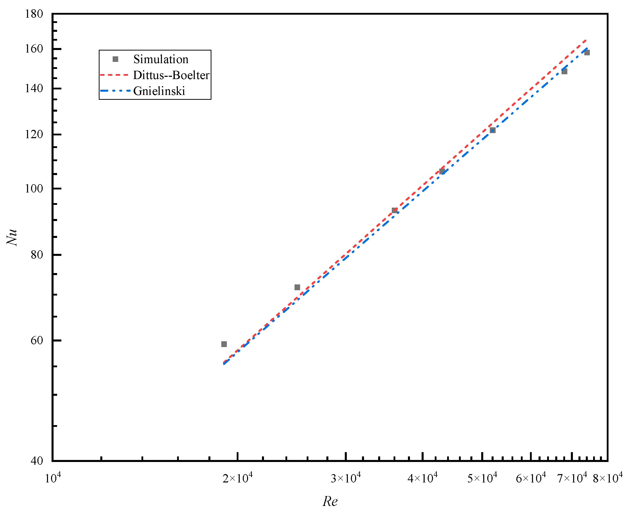
Numerical simulations of turbulent convective heat transfer in a circular pipe were conducted for seven different Reynolds number groups from 104 to 1.2 × 10⁵. Table 3 presents the Reynolds numbers and their corresponding inlet velocities. The numerical results indicated that the relative errors between the Darcy resistance coefficient and the calculated values from the Blasius formula [9] and the Filonenko formula [6] were within 8.04% and 10.03%, respectively. The absolute values of the relative errors between the turbulent heat transfer Nusselt number and the calculated values from the Dittus–Boelter formula [5] and the Gnielinski formula [6,7] were within 6.43% and 6.96%, respectively. The calculated results were in good agreement with those obtained from experimental correlation methods, indicating that our numerical methods and grid division strategies have good predictive capabilities and that the simulations provide reliable results. Figure 2 compares the Nusselt number of turbulent heat transfer in a circular pipe obtained from a simulation using the realizable k–ε model with values calculated from experimental correlations.
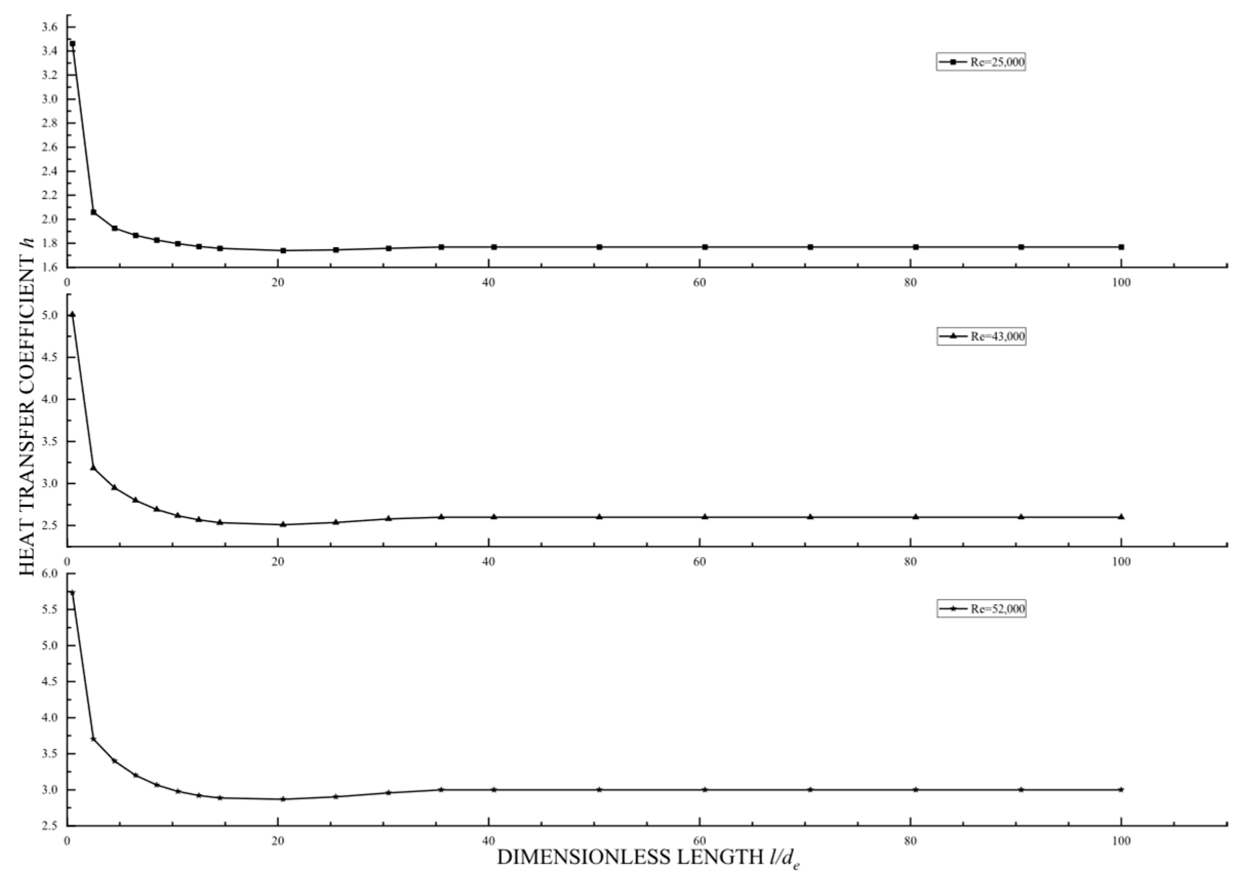
As shown in Figure 3, as the fluid flowed in the inlet section, a thermal boundary layer gradually developed (thickened), and the local surface heat transfer coefficient initially rapidly decreased. As the moving boundary layer developed, the intense mixing caused by turbulence disturbances and fluid micro-groups increased the local surface heat transfer coefficient. Once the fully developed stage was reached, the local surface heat transfer coefficient approached a constant value. Additionally, the length of the thermal entrance region remained mostly unchanged across three different Reynolds numbers, indicating only a weak relationship with the Reynolds number. This is consistent with the results of Tao W. Q. [34], who stated that as long as l/d > 10, the influence of the entrance section during turbulence becomes negligible due to intense mixing between fluid micro-groups. This is also in agreement with Babus’Haq’s [15] experimental results, further validating the reliability of the numerical simulation method and grid partitioning strategy chosen in this paper.

3.2. Concentric Annular Pipeline

This article performed a numerical simulation of turbulent convective heat transfer in concentric annular pipes with inner-to-outer diameter ratios of 0.1, 0.2, 0.25, 0.5, and 0.8, as well as circular pipes.

3.2.1. Flow Characteristics

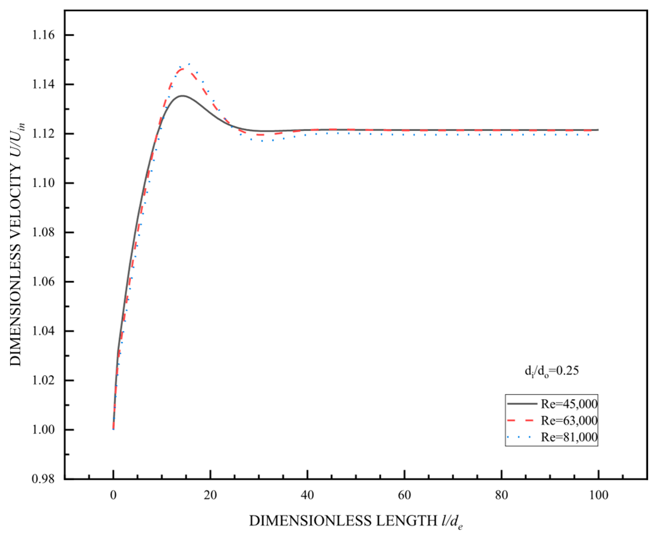
As shown in Figure 4, all dimensionless velocity curves tended to plateau at l/de = 20–40, indicating that the flow was fully developed within 20–40% of the pipe length. The length of the velocity entrance section increased with the Reynolds number. The axial velocity on the center-symmetric plane first reached a maximum before stabilizing within the range of 1.12 to 1.16, indicating that the flow was dominated by the central area of the pipe. The velocity distribution was hardly affected by the wall viscosity. The curves at different Reynolds numbers showed significant separation during the development stage. As the Reynolds number increased, the peak velocity rose higher and stabilized slower, while the velocity variation in the low Reynolds number curves remained relatively smooth. This indicates that at high Reynolds numbers, the flow was more prone to form an accelerating core effect due to the dominance of inertial forces. Once stabilized, the dimensionless velocities corresponding to different Reynolds numbers exhibited differences, indicating that the Reynolds number changed the average velocity in the core region by influencing the intensity of turbulence and viscous dissipation in the flow. All curves remained stable after sufficient development without any periodic fluctuations or intensified turbulent pulsations.
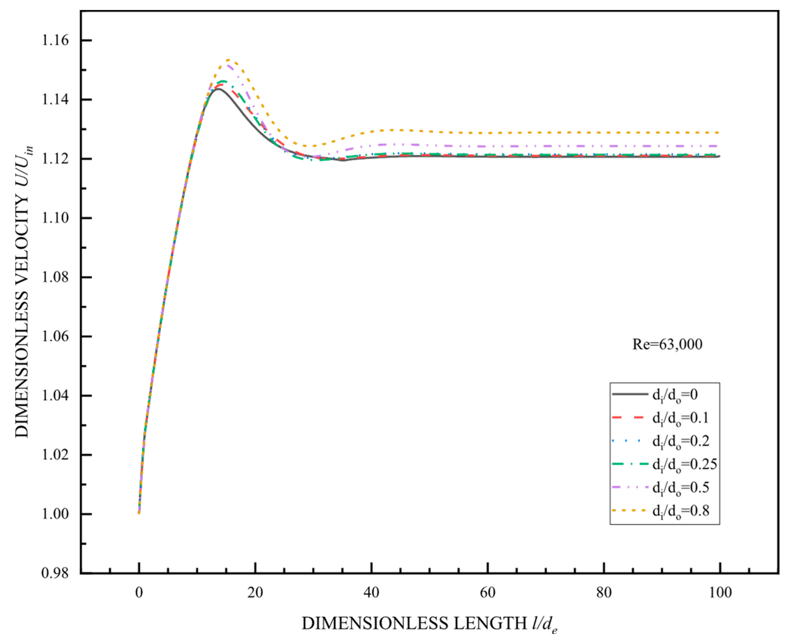
Figure 5 shows the variation curves of the dimensionless velocity along the center-symmetric plane for concentric annular pipes and circular pipes with inner-to-outer diameter ratios of 0.1, 0.2, 0.25, 0.5, and 0.8 at Re = 63,000. The comparison showed that at the same Reynolds number, the length of the velocity inlet section for the circular pipe was the shortest and increased with the inner-to-outer diameter ratio. After entering the fully developed section, the velocity was slightly lower than the peak value. The magnitude of the velocity peak increased with the inner-to-outer diameter ratio, and the position shifted upstream. Below the fully developed section, the increase in the inner-to-outer diameter ratio still led to an increase in the dimensionless velocity within the corresponding pipeline.
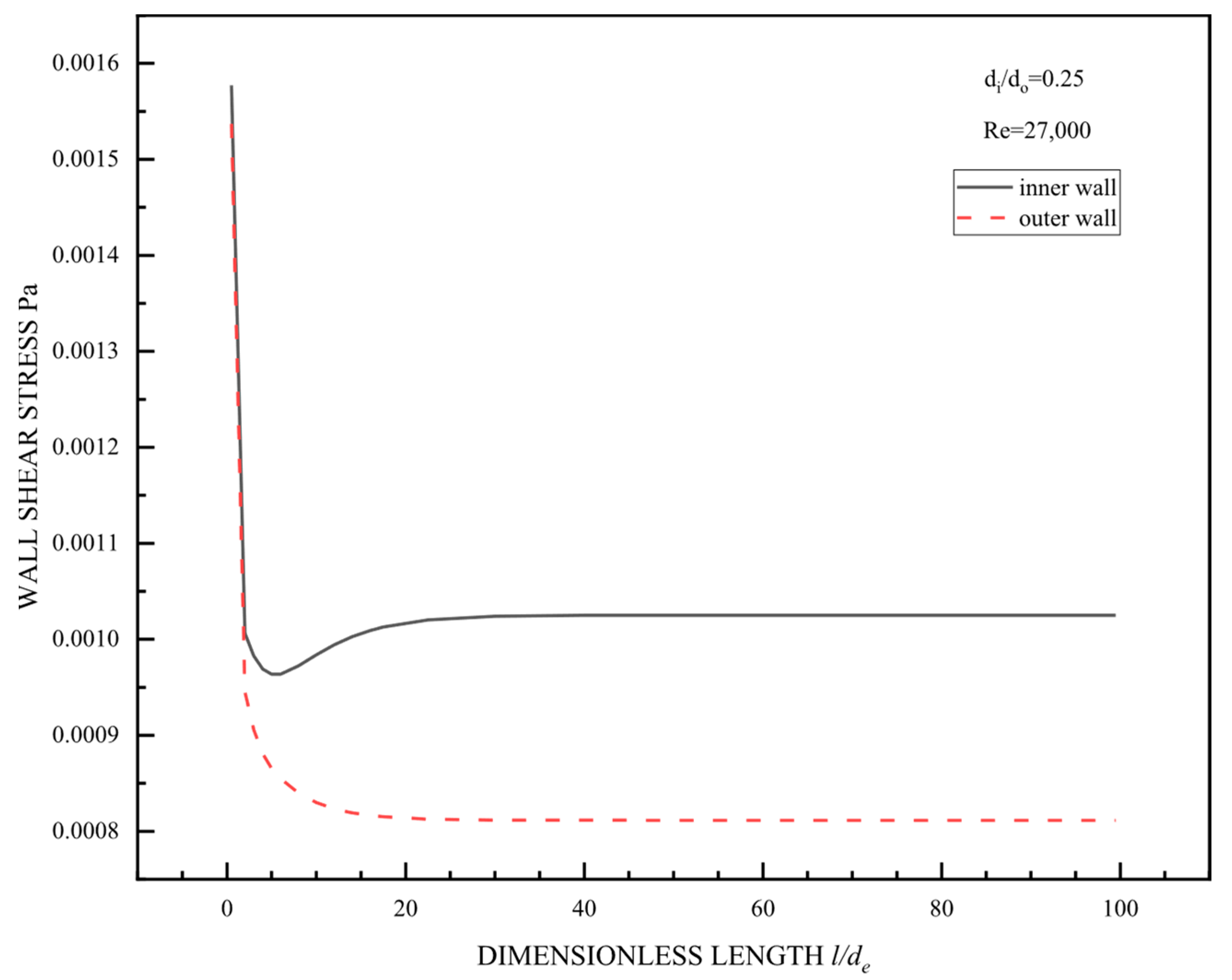
Figure 6 shows that the shear stress on the inner wall surface was always higher than that on the outer wall surface, especially in the fully developed segment, where the difference between the two was more pronounced. The steep decline in the initial section reflects a significant entrance effect, where there was a notable instability in the flow velocity. As the fluid flowed into the fully developed section, the shear stress gradient decreased, and the outer wall reached a steady state earlier than the inner wall. This means that in scenarios when the shear stress exceeds the material’s yield threshold, the inner wall surface is expected to reach a critical flow instability first, while the outer wall surface will experience a similar phenomenon later. This has significant implications for the safety and design of casing heat exchangers and provides critical reference parameters for optimizing the thermal management of concentric annular pipes (where the outer wall surface requires enhanced cooling). This can also help with wear-resistant designs (where the inner wall surface should be prioritized for protection), as well as the flow distribution.

3.2.2. Heat Transfer Characteristics

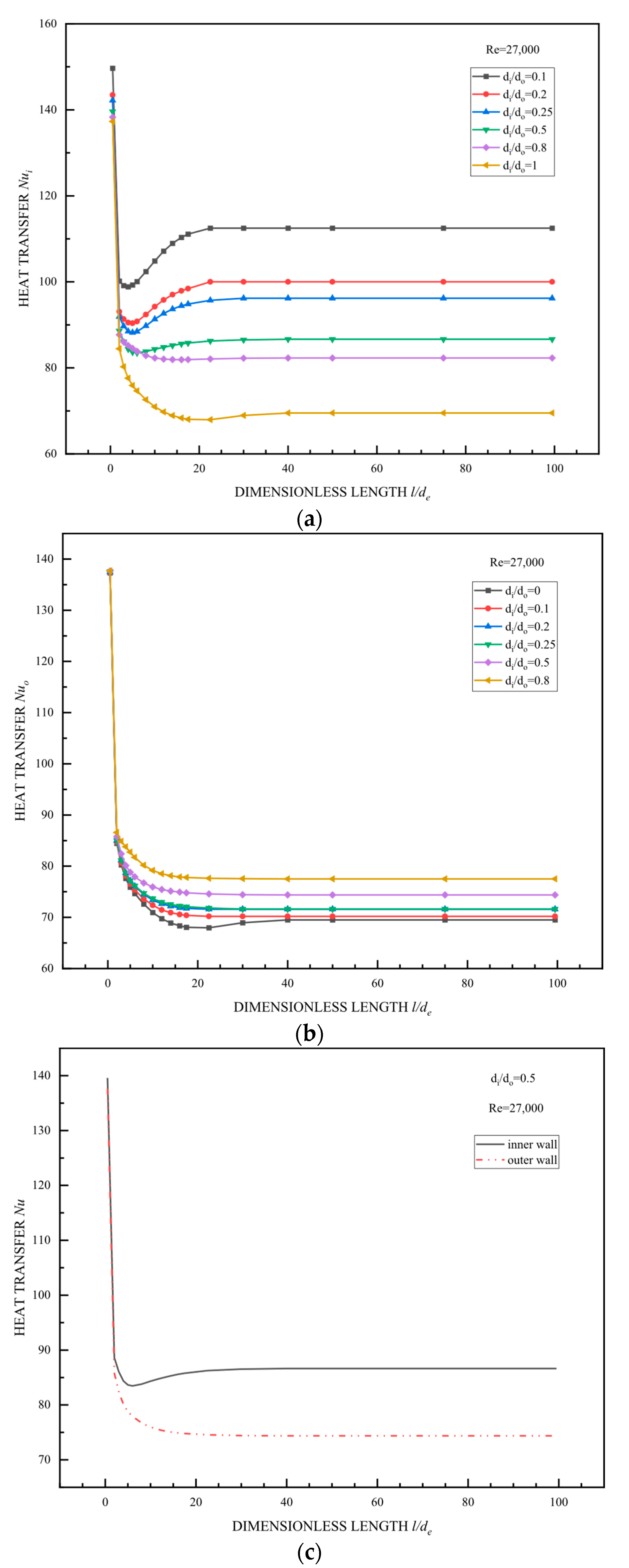
Figure 7a,b show that the Nusselt number decreased rapidly at the beginning before stabilizing. This indicated that during the initial stage of flow, the boundary layer had not fully formed, resulting in a higher heat transfer coefficient. As the boundary layer thickened, heat transfer decreased, leading to a decline in the Nusselt number. The boundary layer continued to develop, and after entering the fully developed region, the heat transfer characteristic values decreased and then stabilized. The Nusselt numbers on both the inner and outer walls of the concentric annular pipe were higher than those of a circular pipe, indicating the superior heat transfer capability of the concentric annular pipe compared with the circular pipe. The curves with higher Nusselt numbers on the inner wall correspond to smaller inner-to-outer diameter ratios, while those with higher Nusselt numbers on the outer wall corresponded to larger inner-to-outer diameter ratios.
In general, as the inner-to-outer diameter ratio increases, the annular gap decreases, as does the fluid passage space, increasing the flow velocity. A high flow velocity enhances turbulent disturbances, disrupts boundary layer stability, reduces boundary layer thickness, decreases thermal resistance, significantly improves the heat transfer coefficient, and substantially enhances heat exchange. Figure 7c shows that the Nusselt numbers on both the inner and outer wall surfaces decreased rapidly during the initial stage of flow before stabilizing. The Nusselt number on the outer wall surface was consistently lower than that on the inner wall surface, and it decreased faster.
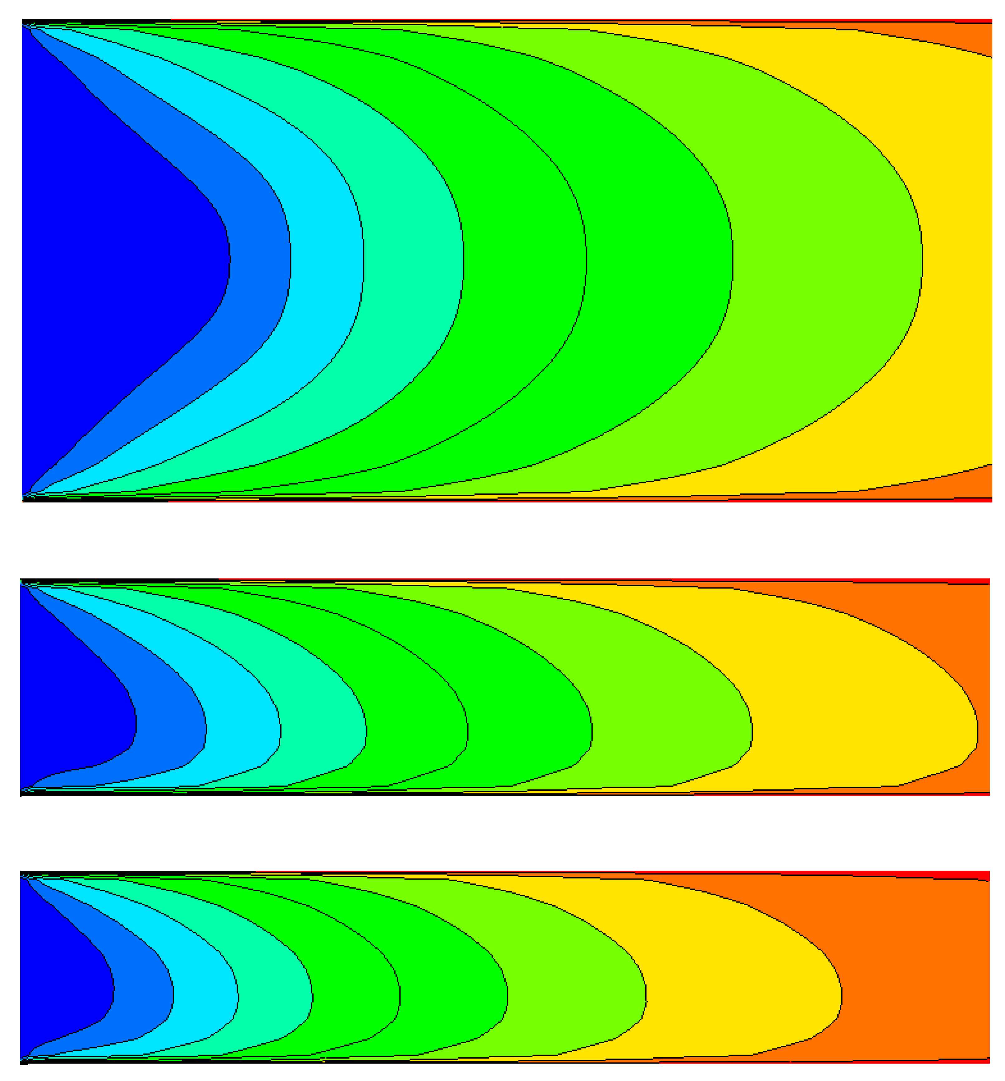
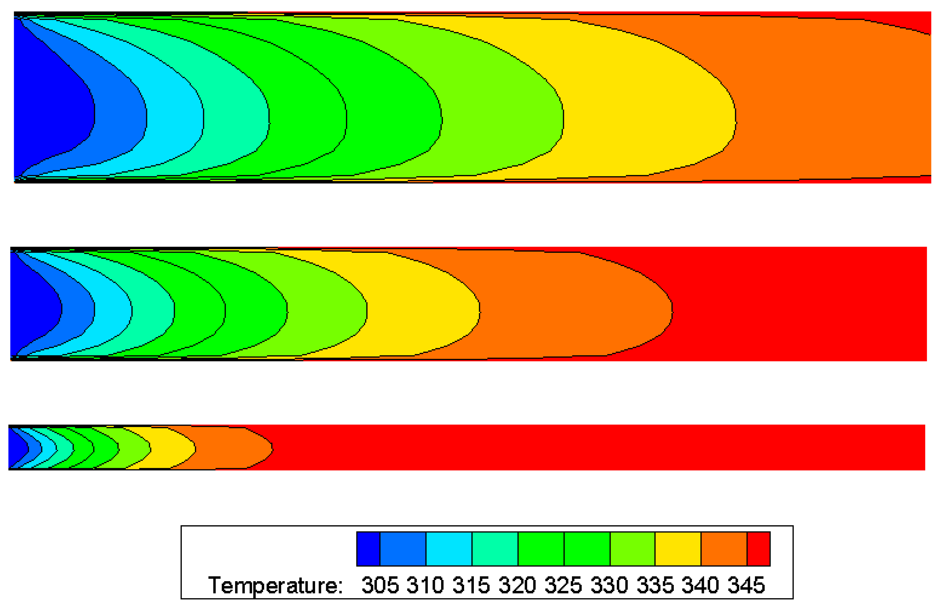
Figure 8 shows that all pipes exhibited a significant axial temperature gradient, with high-temperature zones (red/orange) concentrated at the pipe outlet and low-temperature zones (blue/green) concentrated at the pipe inlet. This indicates that the fluid was heated. As the inner-to-outer diameter ratio increased (narrowing the passage from top to bottom), the temperature gradient significantly strengthened (the distance between adjacent color bands decreased), the temperature difference between the inlet and outlet widened, and the curvature of the isotherms increased. This arose from the reduction in the annular gap, which increased the flow velocity and enhanced the convective heat transfer coefficient (h value increased). This also ultimately increased the heat transfer characteristic values and intensified surface heat transfer.

3.3. Comparison of the Heat Transfer Performance of All Pipelines

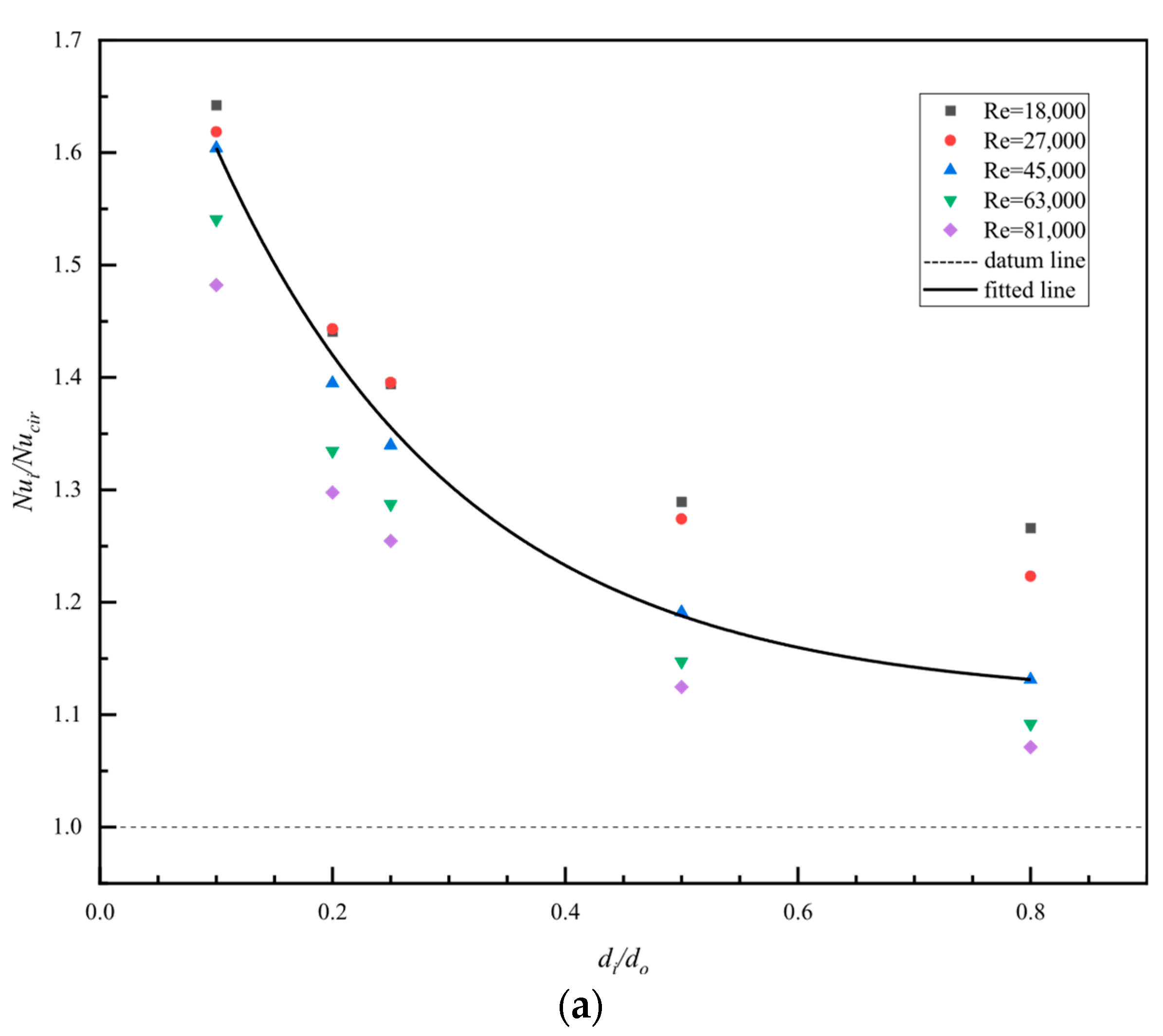
This article performed a numerical simulation for the turbulent convection heat transfer characteristics of concentric annular pipes with different inner-to-outer diameter ratios and circular pipes using multiple sets of different Reynolds numbers. Table 4 present variations in the heat transfer Nusselt numbers on the inner and outer wall surfaces of each pipeline when fully developed. Figure 9 presents the dimensionless ratios Nui/Nucir and Nuo/Nucir of the inner and outer wall surfaces of the concentric annular pipes given in the table and the Nusselt number of circular pipes under the same Reynolds number as a scatterplot. In the figure, the Nucir of the circular pipe is taken as the datum line, with a value of 1. The numerical calculations were used to derive a fitted line, which reflects the ratio of the heat transfer characteristics between the concentric annular pipe and the circular pipe. It should be noted that Nucir in Figure 9 was calculated using the Gnielinski formula.
As shown in Figure 9, in the concentric annular pipe, the Nusselt number of the inner wall decreased upon increasing the inner-to-outer diameter ratio. For instance, for di/do = 0.8 in Figure 9a, the dimensionless ratio of the Nusselt number of the inner wall to that of a circular pipe became closer to the reference line. The Nusselt number on the outer wall increased upon increasing the inner-to-outer diameter ratio, but it changed more slowly than that of the inner wall, as shown by the smaller slope in Figure 9b than the one in Figure 9a. Using the equivalent diameter as a characteristic scale, the correlation formula for turbulent heat transfer obtained from experiments in circular pipes produced significant errors when calculating turbulent convective heat transfer in concentric annular pipes. This error was more pronounced on the inner wall surface of concentric circular pipes, especially when the inner and outer diameters were small, such as di/do = 0.1. The Nusselt number error on the inner wall surface reached 62.43%, while that of the outer wall surface reached 22.20%. When calculating the Nucir term in Figure 9 using the Dittus–Boelter formula, the variation in the heat transfer Nusselt number on the inner and outer surface followed the same trend mentioned above. However, the error on the inner surface reached 60.62%, while that on the outer surface was 19.51%. In situations that do not require a high accuracy, this approach can be used, but for cases requiring a higher accuracy, a correction is needed.
Correction coefficient models that consider the effects of variable properties, helical tubes, transition regions, and rough tubes already exist [35,36,37,38]. Combining these with the variations in the Nusselt number on the inner and outer wall surfaces of the concentric annular pipe (Figure 9), we accounted for how the geometric factor affected the flow and heat transfer in the concentric annular pipe, i.e., variations in the inner-to-outer diameter ratio. Our method introduced a correction coefficient for the inner-to-outer diameter ratio, in which we multiplied the right side of the existing correlation expressions for turbulent heat transfer in circular pipes by Cdi or Cdo. The resulting calculation formula is:
C d i = K i d i d o m i Re n i
C d o = K o d i d o m o Re n o
In the equation, di and do represent the inner and outer diameters of the concentric annular pipe, respectively; Ki, mi, and ni and Ko, mo, and no are the correction factors for the inner and outer diameters, respectively, whose specific values are shown in Table 5.
The revised correlation for turbulent heat transfer in concentric annular pipes is:
N u = C d N u c i r
In the formula, Nucir represents the Dittus–Boelter equation and the Gnielinski equation, which are correlation formulas for turbulent heat transfer in existing circular pipe experiments.
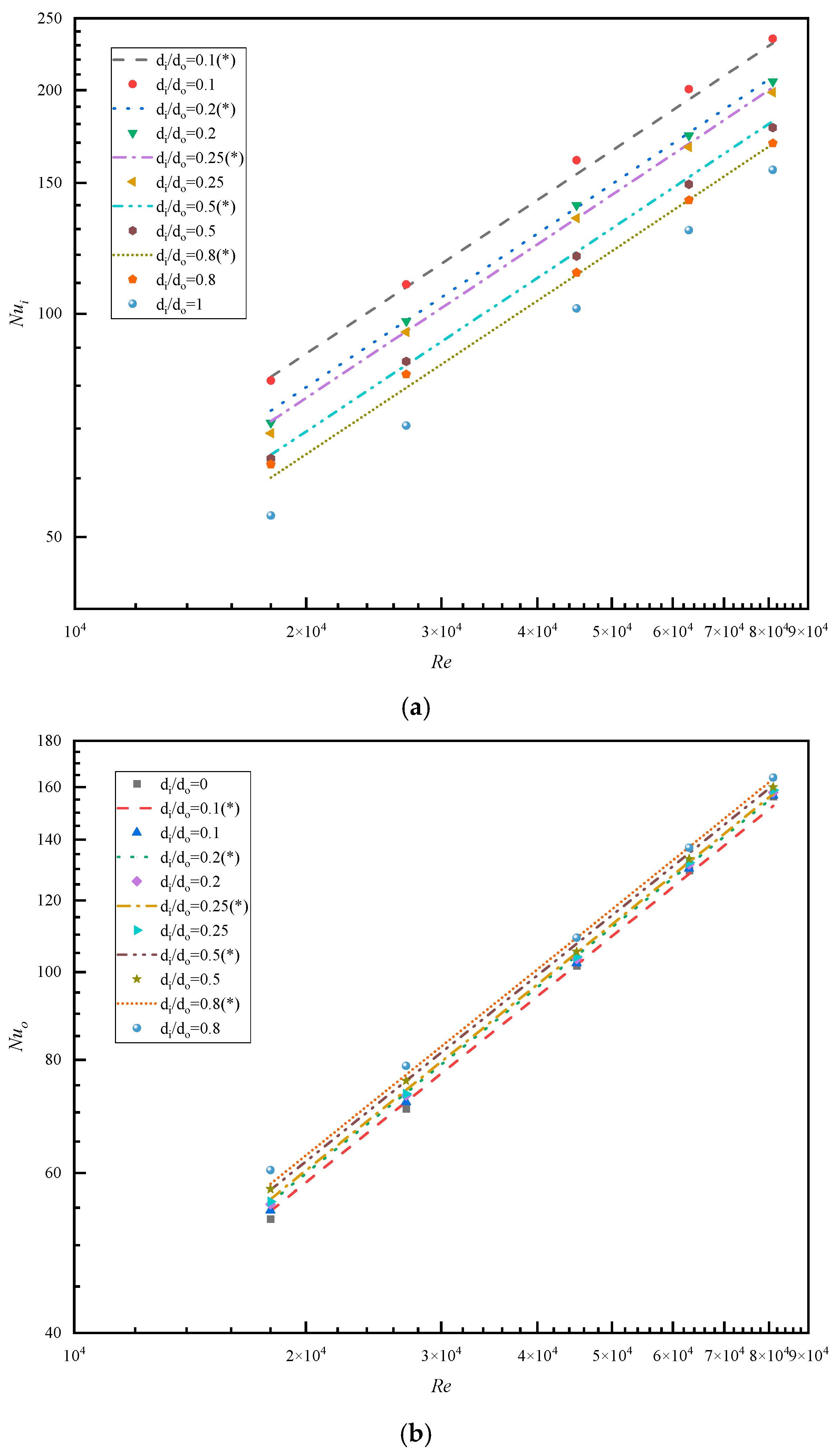
To verify the accuracy of Equation (27), the Gnielinski formula was used as an example for the Nucir term. Using this, we compared the heat transfer Nusselt numbers on the inner and outer wall surfaces of the concentric annular pipe calculated using the modified correlation with the results obtained from numerical simulations, as shown in Figure 10. To provide a clearer comparison, the values calculated using Equation (27) (the modified correlation calculation results) are represented as a line cluster in Figure 10, while the data shown in Table 4 (the numerical simulation results) are represented as scatter points.
Figure 10 shows that the corrected correlation calculations were consistent with the numerical simulation results. In addition, the results predicted by Equation (27) were also in good agreement with those of Jaco Dirker & Meyer [26]. This indicates that the revised correlation enabled differentiated predictions based on the differences in the heat transfer characteristics of inner and outer wall surfaces. It also demonstrates a good predictive capability for the turbulent convection heat transfer characteristics of concentric annular pipes. For the inner wall surface of the concentric annular pipe, the deviation between the corrected empirical calculation value and the numerical simulation result was 4.23%, while it was only 3.44% for the outer wall surface. When the Nucir term in Equation (27) was calculated using the Dittus–Boelter formula, the deviation between the corrected correlation value on the inner wall and the numerical simulation results was 4.26%, while it was only 3.56% for the outer wall.

4. Conclusions

This paper employed realizable k–ε and low Reynolds number models to perform numerical simulations for turbulent convective heat transfer in concentric annular pipes with different inner-to-outer diameter ratios. Under the same Reynolds number, the velocity entrance length of a circular pipe was the shortest, and both the entrance length and peak velocity increased with the inner-to-outer diameter ratio of the concentric annular pipe. The shear stress on the inner wall surface was always higher than that on the outer wall surface, especially in the fully developed section, where the difference between the two was more pronounced.
As the inner-to-outer diameter ratio increased, increases were observed in the temperature gradient, the temperature difference between the inlet and outlet, and the curvature of the isotherms. The convective heat transfer coefficient rose, the heat transfer characteristic values increased, and surface heat transfer intensified. The heat transfer capacity of both the inner and outer wall surfaces increased with the Reynolds number. The shear stress on the inner wall surface and the heat transfer Nusselt number were significantly higher than those on the outer wall surface.
Using the equivalent diameter as a characteristic scale, non-negligible errors will be introduced when using the correlation equations from turbulent heat transfer experiments in circular pipes to calculate the turbulent convective heat transfer in concentric annular pipes. This error was particularly pronounced on the inner wall surface, especially when the inner and outer diameters were relatively small, where the Nusselt number error on the inner wall surface reached 62.43%. This paper proposed a correction factor for the inner-to-outer diameter ratio to achieve differentiated and accurate predictions for the inner and outer wall surfaces. This also clearly demonstrates the effect of the inner-to-outer diameter ratio on heat transfer. For the inner wall surface of the concentric annular pipe, the deviation between the corrected analytical calculation values and the simulation values was 4.23%, while that of the outer wall surface was only 3.44%.

Author Contributions

Methodology, Z.W.; Writing—original draft, J.X.; Supervision, M.Y. All authors have read and agreed to the published version of the manuscript.

Funding

This research received no external funding.

Data Availability Statement

The original contributions presented in this study are included in the article. Further inquiries can be directed to the corresponding author.

Conflicts of Interest

The authors declare no conflict of interest.

References

  1. Xu, K.; He, Y.P.; Wu, D.Y. Calculation and Simulation Analysis of Resistance in Circular Pipelines. J. Chang. Inst. Technol. (Nat. Sci. Ed.) 2015, 16, 51–55. [Google Scholar]
  2. Lv, Y.J.; Peng, Y.S.; Ge, Z.H.; Zhao, P.H. The large eddy simulation study of turbulent heat transfer of liquid metal in a circular pipe. J. Univ. Sci. Technol. China 2015, 45, 917–922. [Google Scholar]
  3. Shah, R.K.; London, A.L. Laminar flow forced convection in ducts. In Advances in Heat Transfer; Supplement 1; Hartnett, J.P., Irvine, T.F., Eds.; Academic Press: New York, NY, USA, 1978; pp. 78–384. [Google Scholar]
  4. Yang, S.M.; Tao, W.Q. Heat Transfer, 4th ed.; Higher Education Press: Beijing, China, 2006; pp. 243–252. [Google Scholar]
  5. Dittus, F.W.; Boelter, L.M.K. Heat transfer in automobile radiators of the tubular type. Int. Commun. Heat Mass Transf. 1985, 1, 3–22. [Google Scholar] [CrossRef]
  6. Gnielinski, V. New equations for heat and mass transfer in turbulent pipe and channel flows. Int. Chem. Eng. 1976, 2, 359–368. [Google Scholar]
  7. Gnielinski, V. On heat transfer in tubes. Int. J. Heat Mass Transf. 2013, 63, 134–140. [Google Scholar] [CrossRef]
  8. Wang, P.; Yang, M.; Wang, Z.Y.; Xu, H.T. Numerical simulation of turbulent heat transfer of non-circular channel non-Newtonian fluid. J. Eng. Thermophys. 2014, 35, 2269–2273. [Google Scholar]
  9. Wang, P.; Yang, M.; Wang, Z.Y.; Xu, H.T. A new heat transfer correlation for turbulent flow of air with variable properties in noncircular ducts. ASME J. Heat Transf. 2014, 136, 101701-1–101701-08. [Google Scholar] [CrossRef]
  10. Yang, M.; Wang, X.M.; Wang, Z.Y.; Li, Z.; Zhang, Y.W. Correlation for turbulent convection heat transfer in elliptical tubes by numerical simulations. Front. Heat Mass Transf. 2018, 11, 7. [Google Scholar] [CrossRef]
  11. Qiao, L. Numerical Simulation of Turbulent Flow and Heat Transfer in a Rectangular Cross-Section Channel. Master’s Thesis, University of Shanghai for Science and Technology, Shanghai, China, 2015. [Google Scholar]
  12. Wang, S.S.; Xu, W.Q.; Hu, Y.H. Characterization of convective heat transfer and flow resistance in elliptical tubes. Ind. Heat. 2010, 39, 13–16. [Google Scholar]
  13. Yang, M.; Lu, H.T.; Zhao, Y.S.; Lu, T.K.; Dai, Z.H. Numerical experiments on turbulent convective heat transfer in a longitudinally swept tube bundle and its correlation equation. J. Univ. Shanghai Sci. Technol. 2017, 39, 110–113. [Google Scholar]
  14. Bagheri, E.; Wang, B.C. Direct numerical simulation of turbulent heat transfer in concentric annular pipe flows. Phys. Fluids 2021, 33, 055131. [Google Scholar] [CrossRef]
  15. Babus’Haq, R.F. Forced convection heat transfer from a pipe to air flowing turbulently inside it. Exp. Heat Transf. 1992, 59, 161–173. [Google Scholar] [CrossRef]
  16. Zhang, L.Y. Analytical Modeling and Characterization of Heat Transfer in a Coaxial Cased Medium-Depth Geothermal Heat Exchanger. Master’s Thesis, Qingdao University of Technology, Qingdao, China, 2024. [Google Scholar]
  17. Yin, Y.D.; Nong, Y.S.; Li, Y.Y.; Liu, S.J. Enhanced heat transfer and flow resistance characteristics of twisted tube coaxial casing heat exchangers. J. Chem. Eng. 2024, 75, 3528–3535. [Google Scholar]
  18. Li, W.J.; Yao, H.Q.; Zhao, S.W.; Zhang, W.K.; Sun, W.F.; Sun, Z.X. Analysis of heat transfer in porous cased heat exchangers with different arrangements. Build. Energy Effic. 2023, 51, 77–85. [Google Scholar]
  19. Huang, B. Research on Coupled Heat Transfer Characteristics of Cased Heat Exchanger with Inner Tube Filled with Porous Medium. Masteri’s Thesis, Huazhong University of Science and Technology, Wuhan, China, 2021. [Google Scholar]
  20. He, C.S. Research on prestressing technology of large-scale double-casing rapid cooling heat exchanger. China Boil. Press. Vessel. Saf. 2007, 35, 13–15. [Google Scholar]
  21. Boersma, B.-J.; Breugem, W.-P. Numerical simulation of turbulent flow in concentric annuli. Flow Turbul. Combust. 2011, 86, 113–127. [Google Scholar] [CrossRef]
  22. Bai, B.F.; Wang, Y.C.; Xiao, Z.J. Experimental study of forced flow and heat transfer in a concentric annular tube. Chem. Eng. 1998, 15, 14–19. [Google Scholar]
  23. Bao, L.L.; Xu, B.; Wang, Z.Y.; Li, B.J.; Luo, J.H. Analysis of heat transfer performance of medium-depth coaxial cased buried tube heat exchanger. Adv. Geophys. 2020, 35, 1217–1222. [Google Scholar]
  24. Liu, Z.; Liu, S.Y.; Gao, S. Research on the effect of tube diameter ratio on heat transfer performance of medium-depth buried tube heat exchanger. Electr. Power Explor. Des. 2021, 9, 67–73. [Google Scholar]
  25. Zhang, B.Z.; Chen, H.J.; Zhang, J.S. Flow field structure and heat transfer characteristics in a rotating annular section bent tube. J. Aerodyn. 2002, 20, 21–31. [Google Scholar]
  26. Dirker, J.; Meyer, J.P. Heat transfer coefficients in concentric annuli. Heat Transf. 2002, 124, 1001–1008. [Google Scholar] [CrossRef]
  27. Shao, J.; Li, X.H.; Guo, Z.J.; Liu, R.J.; Tian, X.L. Study on the applicability of different turbulence models in numerical simulation of pipeline flow. Chem. Equip. Pip. 2016, 53, 66–71. [Google Scholar]
  28. Mohammad, H.Z.; Mona, Z.P.; Siamak, H.; Kambiz, V. Application of Porous-Embedded shell and tube heat exchangers for the Waste heat Recovery Systems. Appl. Therm. Eng. 2022, 211, 118452. [Google Scholar] [CrossRef]
  29. ANSYS, Inc. ANSYS Fluent Theory Guide [CP/OL]; ANSYS: Canonsburg, PA, USA, 2020. [Google Scholar]
  30. Jones, W.P.; Launder, B.E. The prediction of laminarization with a two-equation model of turbulence. Int. J. Heat Mass Transf. 1972, 15, 301–311. [Google Scholar] [CrossRef]
  31. Jones, W.P.; Launder, B.E. The calculation of low-Reynolds-number phenomena with a two-equation model of turbulence. Int. J. Heat Mass Transf. 1973, 16, 1119–1130. [Google Scholar] [CrossRef]
  32. Tao, W.Q. Numerical Heat Transfer, 2nd ed.; Xi’an Jiaotong University Press: Xi’an, China, 2001; pp. 227–370. [Google Scholar]
  33. Han, Z.Z. FLUENT—Fluid Engineering Simulation Case Studies and Analysis; Beijing Institute of Technology Press: Beijing, China, 2009; pp. 103–104. [Google Scholar]
  34. Tao, W.Q. Heat Transfer, 5th ed.; Higher Education Press: Beijing, China, 2019; pp. 230–231. [Google Scholar]
  35. Thermal Calculation Standard Method for Boiler Units; Beijing Boiler Factory Design Department, Translator; Machinery Industry Press: Beijing, China, 1976; pp. 47–75. [Google Scholar]
  36. Shah, R.K.; Joshi, S.D. Handbook of Single-Phase Convective Heat Transfer; Wiley-Interscience: New York, NY, USA, 1987; Chapter 5. [Google Scholar]
  37. Ghajar, A.J.; Tam, L.M. Heat transfer measurements and correlations in the transition region for a circular tube with three different inlet configurations. Exp. Therm. Fluid Sci. 1994, 8, 79–90. [Google Scholar] [CrossRef]
  38. Ji, W.T.; Zhang, D.C.; He, Y.L.; Tao, W.Q. Prediction of fully developed turbulent heat transfer of internal helically ribbed tubes--An extension of Gnielinski equation. Int. J. Heat Mass Transf. 2012, 55, 1375–1384. [Google Scholar] [CrossRef]
Figure 1. Sample of the computational mesh.
Energies 18 03643 g001
Figure 2. Comparison of simulated Nusselt number values for circular pipes with experimental correlation values.
Energies 18 03643 g002
Figure 3. Variation in local surface heat transfer coefficient in a circular pipe at different Reynolds numbers.
Energies 18 03643 g003
Figure 4. Variations in dimensionless velocity along the center symmetry plane of concentric annular pipes at different Reynolds numbers.
Energies 18 03643 g004
Figure 5. Variations in dimensionless velocity along the center-symmetric plane.
Energies 18 03643 g005
Figure 6. Shear force distribution along the inner and outer wall surfaces of a concentric annular pipe.
Energies 18 03643 g006
Figure 7. Axial variations in the heat transfer Nusselt number: (a) inner wall surface; (b) outer wall surface; (c) comparison of the axial variations in the heat transfer Nusselt number on the inner and outer wall surfaces.
Energies 18 03643 g007
Figure 8. Temperature distribution.
Energies 18 03643 g008aEnergies 18 03643 g008b
Figure 9. Dimensionless ratio of Nusselt number for concentric annular pipes and circular pipes: (a) inner wall surface; (b) outer wall surface.
Energies 18 03643 g009aEnergies 18 03643 g009b
Figure 10. Comparison of corrected analytical calculation values and numerical simulation results: (a) Nusselt number of the inner wall surface Nui; (b) Nusselt number of the outer wall surface Nuo.
Energies 18 03643 g010
Table 1. Nusselt number variations in concentric circular pipes with respect to the number of cross-sectional grids.
Mesh Size1664 × 2001876 × 2002058 × 2002230 × 2002482 × 200
N u i 69.2169.0468.9768.9468.89
N u o 55.9355.8755.8455.8355.82
Table 2. Nusselt number variations in concentric annular pipes with respect to the number of grid points in the flow direction.
Mesh Size2058 × 1002058 × 1502058 × 2002058 × 2502058 × 300
N u i 68.9868.9868.9768.9668.96
N u o 55.8255.8355.8455.8555.85
Table 3. Reynolds numbers and their corresponding inlet velocities.
Re19,00025,00036,00043,00052,00068,00074,000
Inlet velocity (m/s)0.380.50.720.861.041.361.48
Table 4. Nusselt numbers for heat transfer on the inner and outer wall surface when fully developed.
R e
di/do
N u i
0.10.20.250.50.81
18,00081.24 71.28 68.97 63.79 62.64 53.45
27,000109.53 97.69 94.45 86.22 82.78 70.64
45,000160.99 139.98 134.45 119.54 113.54 101.61
63,000200.60 173.80 167.64 149.39 142.17 129.55
81,000234.67 205.48 198.64 178.08 169.61 156.24
R e
di/do
N u o
00.10.20.250.50.8
18,00053.4554.62 55.49 55.84 57.64 60.45
27,00070.6471.89 73.08 73.37 75.88 78.81
45,000101.61102.30 103.41 103.97 105.33 109.11
63,000129.55130.16 131.46 132.17 133.33 137.18
81,000156.24156.67 157.92 158.83 160.04 163.97
Table 5. Correction coefficient parameter table.
K i m i n i K o m o n o
D–B3.441−0.15−0.1123.6180.033−0.116
Gnielinski2.704−0.15−0.0852.8430.033−0.089
Disclaimer/Publisher’s Note: The statements, opinions and data contained in all publications are solely those of the individual author(s) and contributor(s) and not of MDPI and/or the editor(s). MDPI and/or the editor(s) disclaim responsibility for any injury to people or property resulting from any ideas, methods, instructions or products referred to in the content.