
Optimizing Solvent-Assisted SAGD in Deep Extra-Heavy Oil Reservoirs: Mechanistic Insights and a Case Study in Liaohe


Abstract
1. Introduction
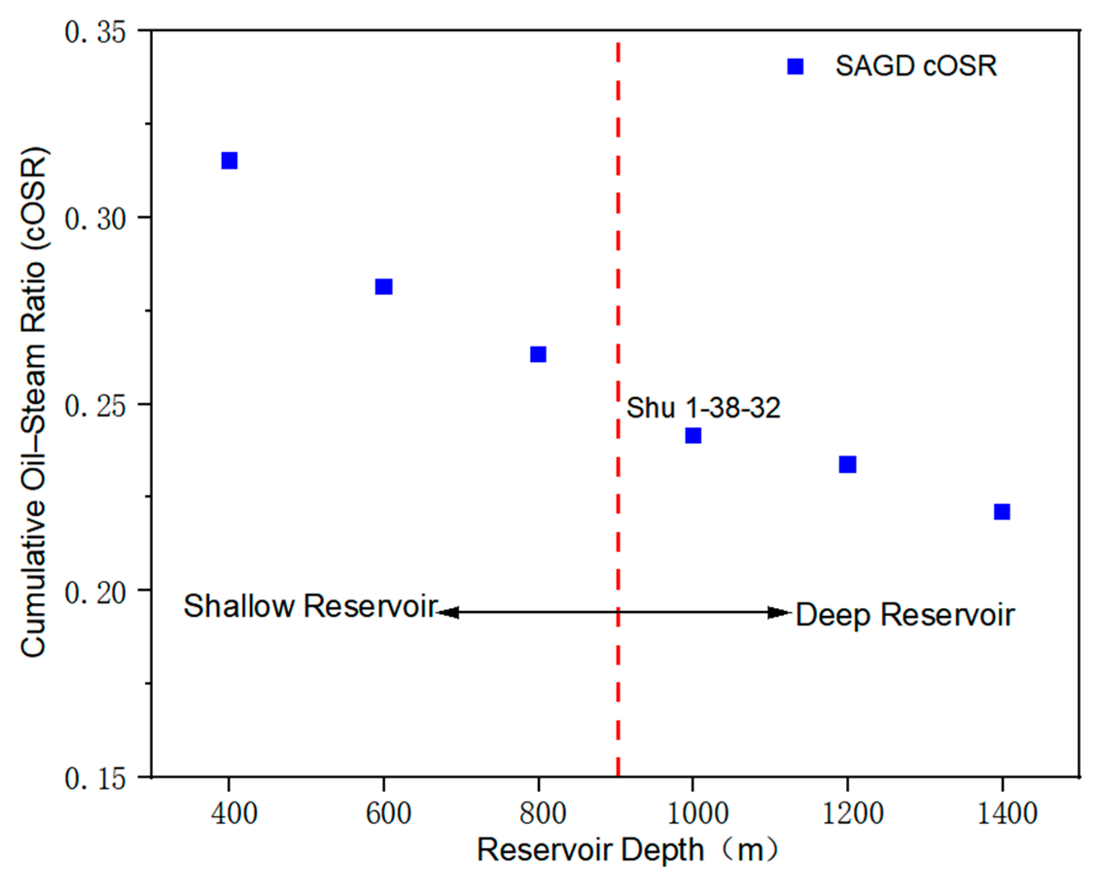
2. Theoretical Analysis of the Effect of Depth on SAGD Production
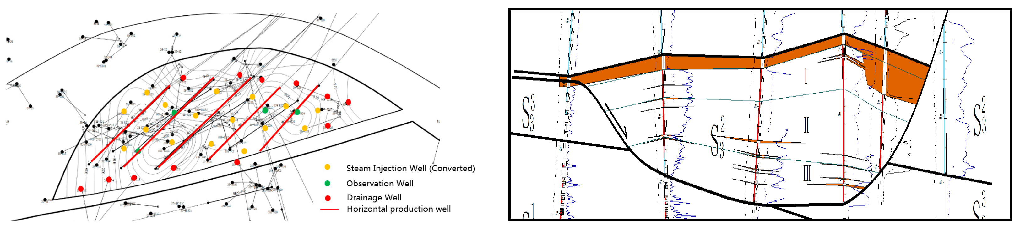
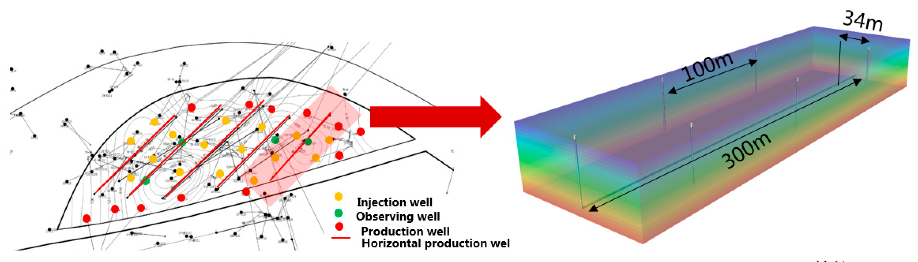
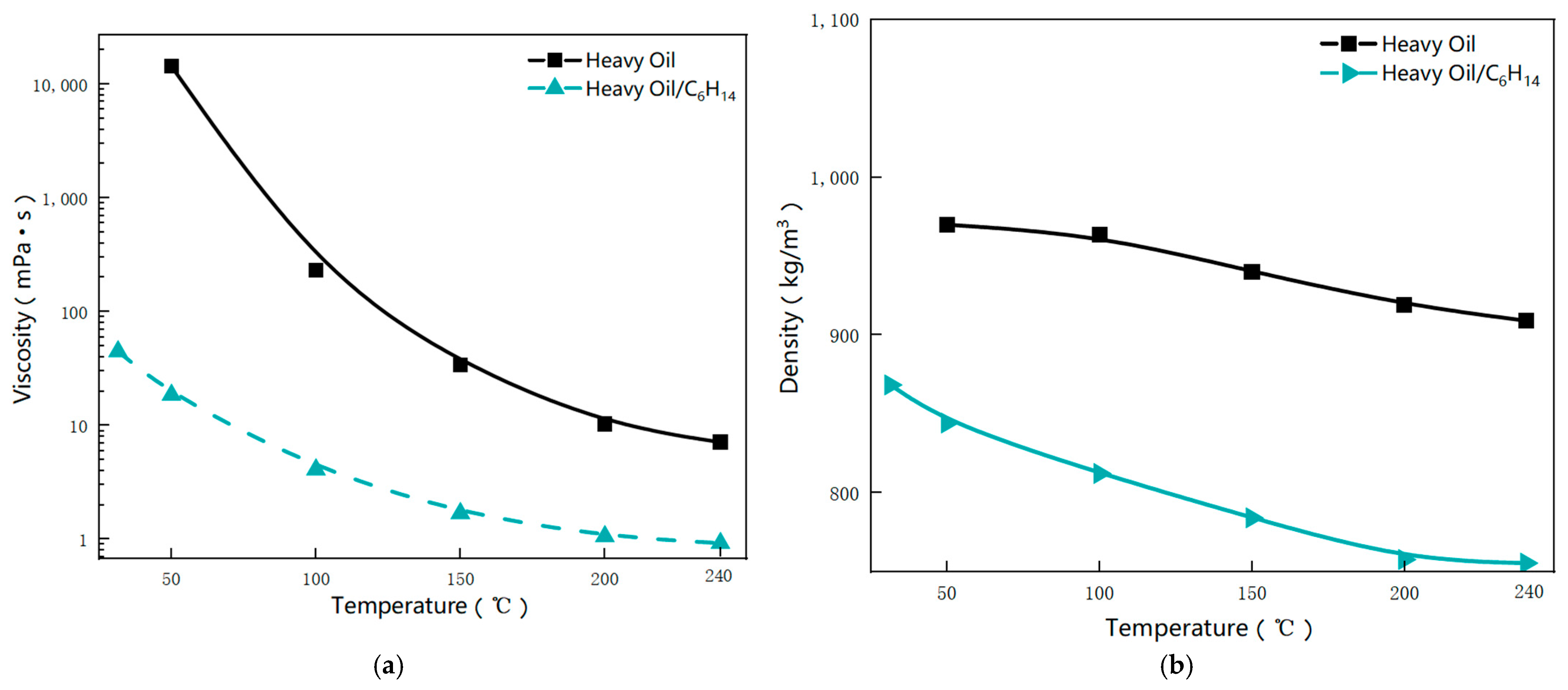
2.1. Reservoir Description
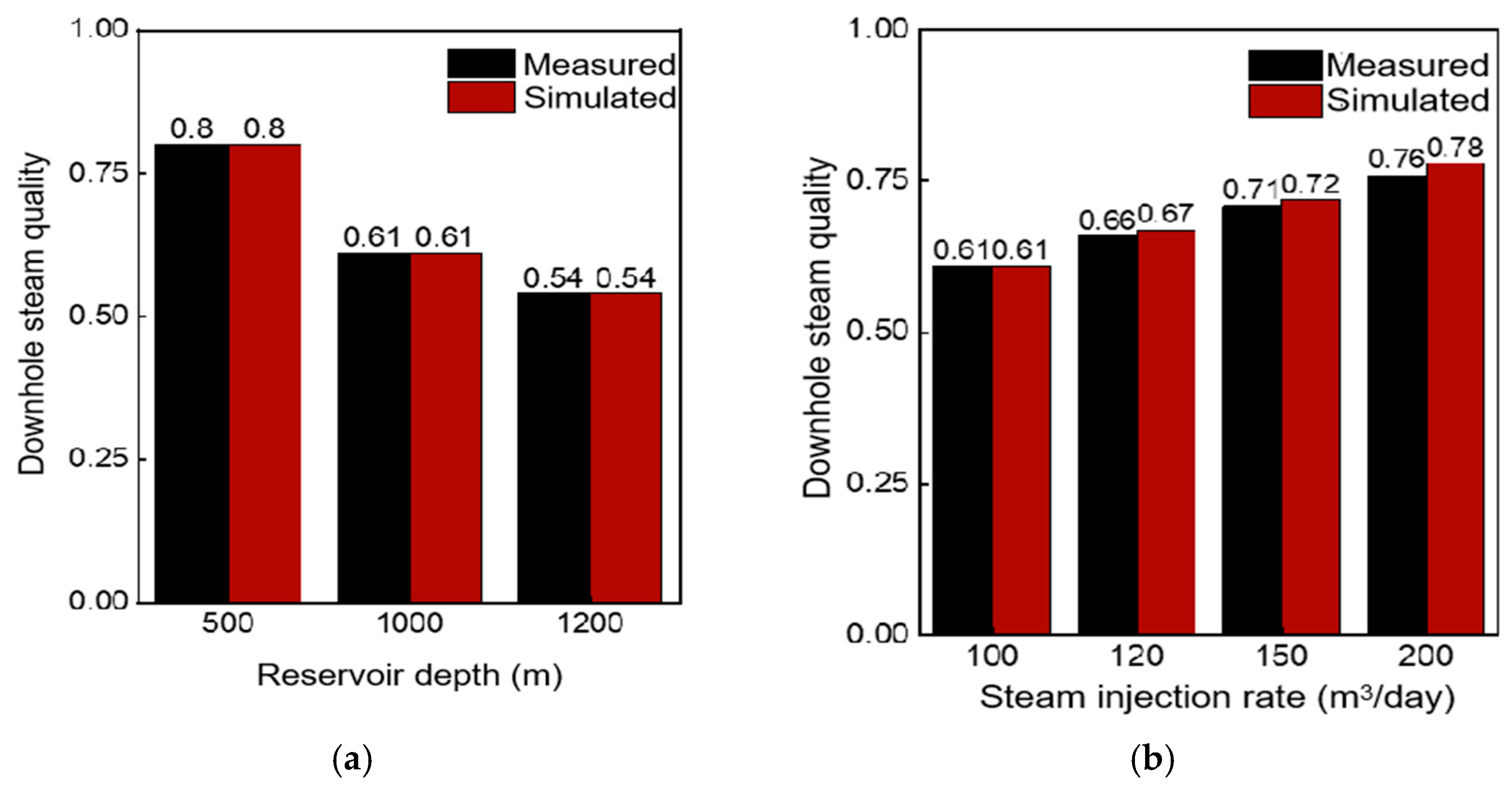
2.2. Wellbore Steam Quality Simulation
2.3. Analytical Model on the Effect of Depth
3. Numerical Simulation Study on ES-SAGD Mechanism
3.1. Model Development
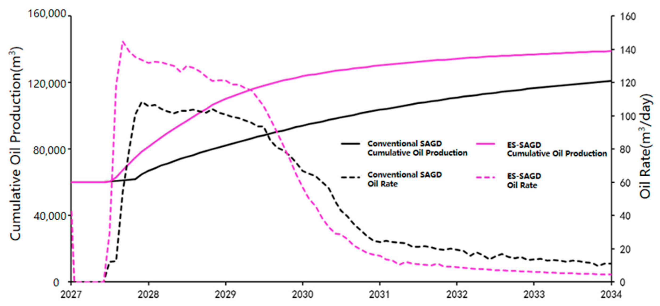
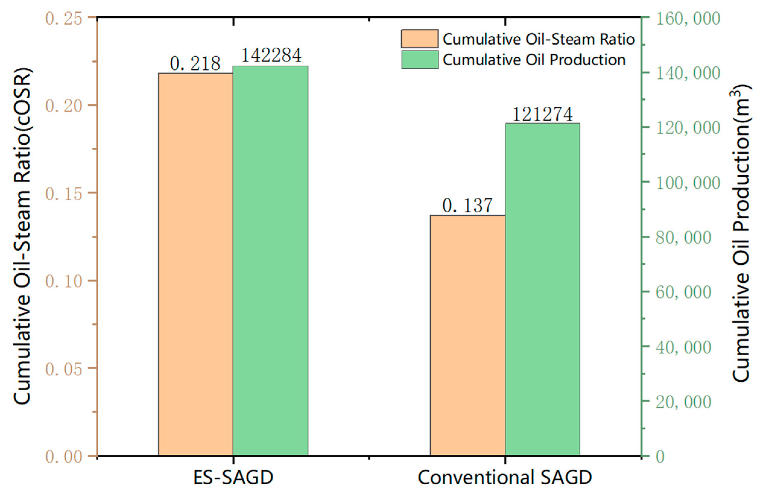
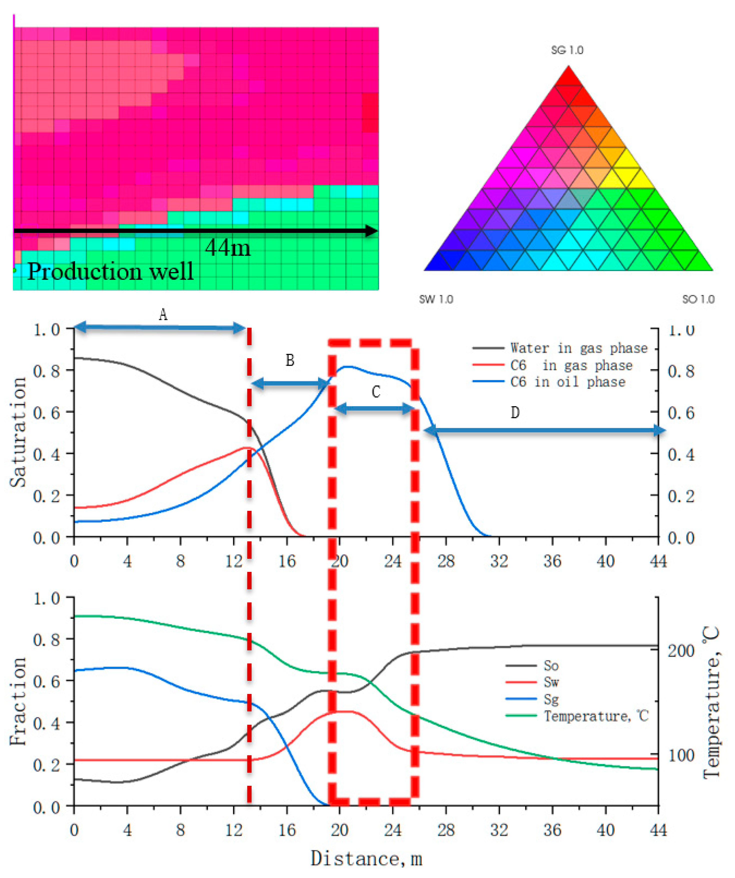
3.2. Comparison of ES-SAGD vs. SAGD
4. Operational Optimization and Pilot Performance Forecasting for ES-SAGD
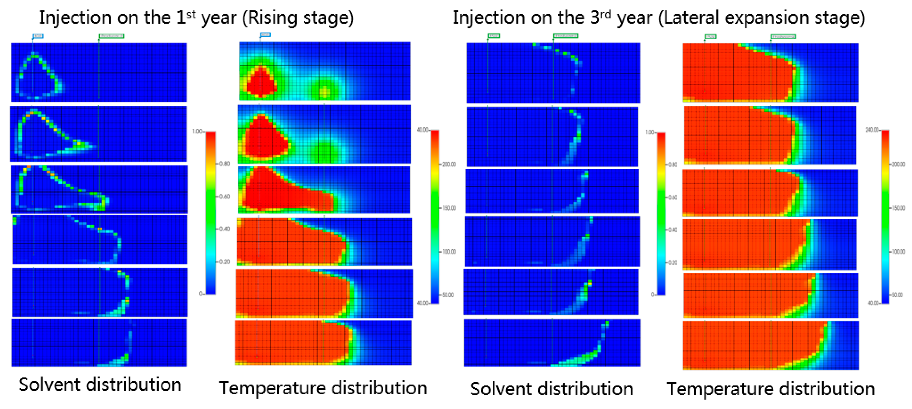
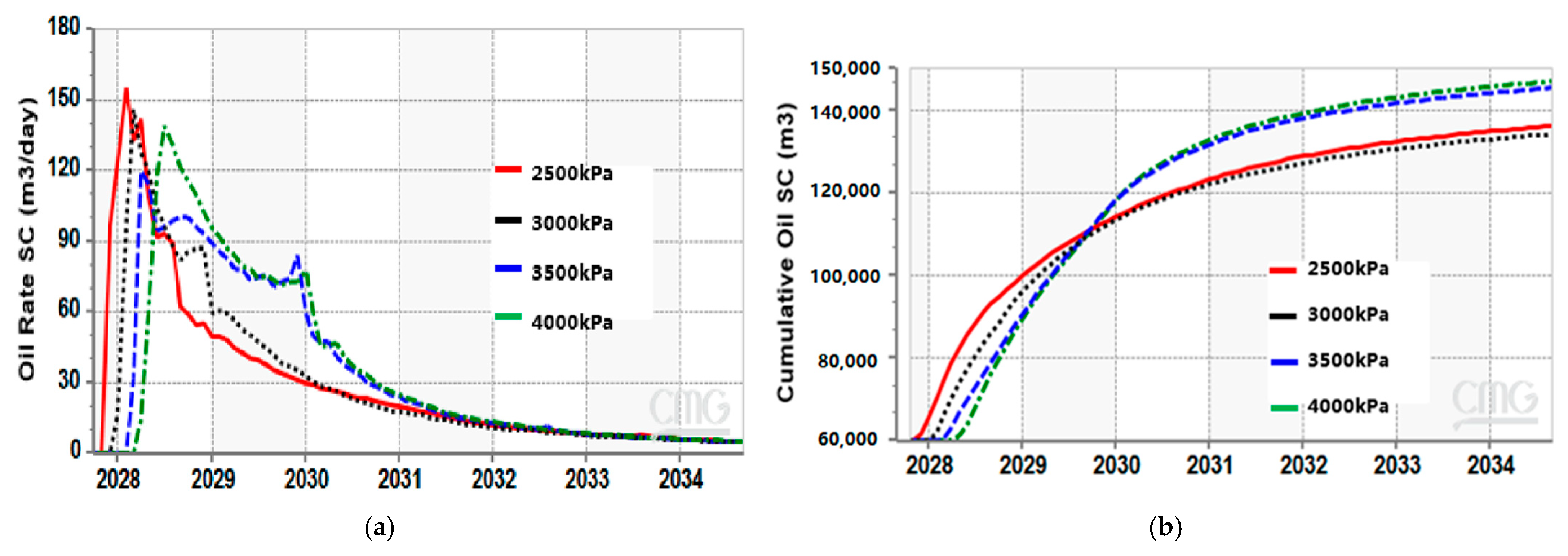
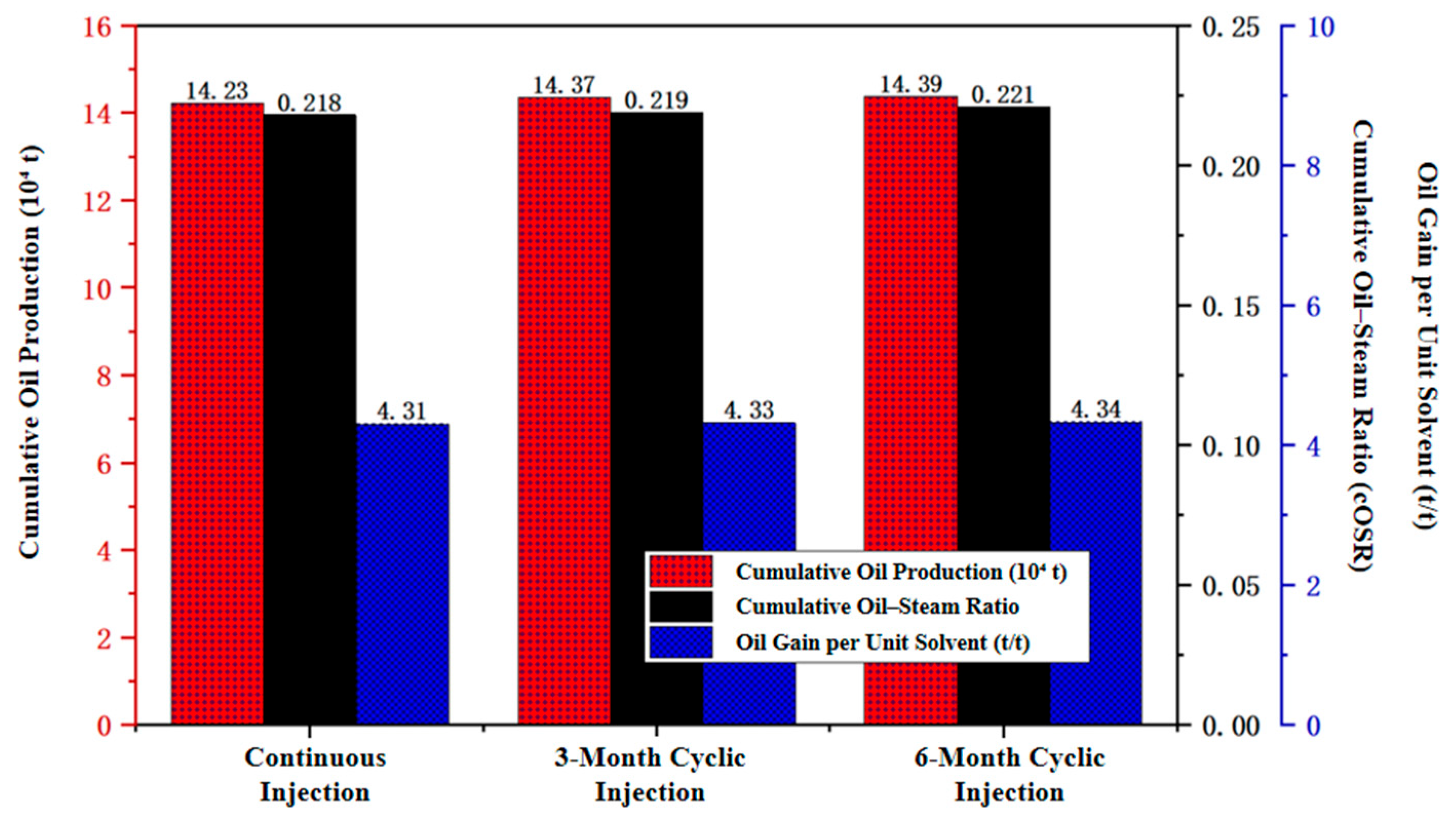
4.1. Operational Parameters Optimization on ES-SAGD
4.2. Pilot Performance Forecasting for ES-SAGD
5. Conclusions
- Depth-induced steam quality degradation is identified as the primary limitation to SAGD efficiency in deep extra-heavy oil reservoirs. Theoretical modifications to the Butler model reveal that declining steam quality with increasing burial depth significantly reduces productivity and the cumulative oil–steam ratio.
- Numerical simulations demonstrate the technical feasibility of ES-SAGD using 3 vol% n-hexane, achieving a 36.5% higher peak oil production and a 17.3% increase in cumulative oil recovery compared to conventional SAGD. The solvent recovery factor exceeds 72%, with an oil gain per unit of the solvent mass of approximately 4.31 t/t.
- Sensitivity analysis shows that optimal ES-SAGD performance is achieved when using the 3 vol% solvent concentration, employing cyclic injections during the lateral expansion phase, and utilizing operating pressure maintained above 3 MPa. Under these conditions, the process achieves a cOSR of 0.218.
- Pilot-scale forecasting confirms the economic viability of ES-SAGD in the Shu 1-38-32 block. The cumulative oil recovery factor improved from 28.7% to 63.3% over a seven-year development period, with the projected cOSR rising from 0.13 to 0.19.
Author Contributions
Funding
Data Availability Statement
Conflicts of Interest
Abbreviations
| ES-SAGD | Expanding Solvent Steam-Assisted Gravity Drainage |
| SAGD | Steam-Assisted Gravity Drainage |
| cOSR | Cumulative Oil–Steam Ratio |
| SOR | Steam–Oil Ratio |
| OOIP | Original Oil in Place |
| NCG | Non-Condensable Gas |
| PVT | Pressure–Volume–Temperature |
| Change in Oil Saturation | |
| Effective Oil Saturation Change due to Latent Heat | |
| h | Reservoir Thickness |
| x | Steam Quality (dryness fraction) |
| α | Fractional Conversion of Solvent |
| t/t | Ton per Ton (e.g., oil produced per unit solvent used) |
References
- Li, Q.; Li, Q.; Wang, F.; Xu, N.; Cao, H.; Wang, Y. Settling behavior and mechanism analysis of kaolinite as a fracture proppant of hydrocarbon reservoirs in CO2 fracturing fluid. Colloids Surf. A Physicochem. Eng. Asp. 2025, 724, 137463. [Google Scholar] [CrossRef]
- Xie, H.; Zhang, S.; Wu, G.; Li, W. Study on Thermal Chamber Expansion of VH-SAGD Process Using CO2-Inducing Effect for Heavy Oil Reservoirs. Processes 2024, 12, 2260. [Google Scholar] [CrossRef]
- Jiang, Q.; Liu, Y.; Zhou, Y.; Wang, Z.; Gong, Y.; Jiang, G.; Huang, S.; Yu, C. Improving Thermal Efficiency and Reducing Emissions with CO2 Injection during Late Stage SAGD Development. Processes 2024, 12, 1166. [Google Scholar] [CrossRef]
- Xiong, R.; Guo, J.; Kiyingi, W.; Gao, C.; Wang, L.; Luo, J.; Song, H.; Wang, X. Technical transformation of heavy/ultra-heavy oil production in China driven by low carbon goals: A review. J. Clean. Prod. 2024, 458, 142531. [Google Scholar] [CrossRef]
- Minakov, A.V.; Meshkova, V.D.; Guzey, D.V.; Pryazhnikov, M.I. Recent advances in the study of in situ combustion for enhanced oil recovery. Energies 2023, 16, 4266. [Google Scholar] [CrossRef]
- Esmaeili, S.; Maini, B.; Ul Abidin, Z.; Kantzas, A. Experimental Investigation of the Effect of Solvent Type and Its Concentration on the Performance of ES-SAGD. Methods Protoc. 2025, 8, 39. [Google Scholar] [CrossRef] [PubMed]
- Nasr, T.N.; Beaulieu, G.; Golbeck, H.; Heck, G. Novel expanding solvent-SAGD process “ES-SAGD”. J. Can. Pet. Technol. 2003, 42. [Google Scholar] [CrossRef]
- Govind, P.A.; Das, S.; Srinivasan, S.; Wheeler, T.J. Expanding solvent SAGD in heavy oil reservoirs. In Proceedings of the SPE International Thermal Operations and Heavy Oil Symposium, Calgary, AB, Canada, 20–23 October 2008; SPE: Richardson, TX, USA, 2008; p. SPE-117571-MS. [Google Scholar]
- Xu, H.; Li, Z.; Li, Y.; Song, H. Catalytic asphaltene upgrading under methane environment: Solvent effect and its interaction with oil components. Fuel 2021, 291, 120157. [Google Scholar] [CrossRef]
- Dittaro, L.M.; Jaafar, A.E.; Perlau, D.L.; Boone, T.J.; Yerian, J.A.; Dickson, J.L.; Wattenbarger, R.C. Findings from a solvent-assisted SAGD pilot at Cold Lake. In Proceedings of the SPE Canada Heavy Oil Conference, Calgary, AB, Canada, 11–13 June 2013; SPE: Richardson, TX, USA, 2013; p. SPE-165434-MS. [Google Scholar]
- Dickson, J.L.; Scott, C.; Dittaro, L.M.; Jaafar, A.E.; Yerian, J.A.; Perlau, D.L. Design approach and early field performance for a solvent-assisted SAGD pilot at Cold Lake, Canada. In Proceedings of the SPE International Heavy Oil Conference and Exhibition, Kuwait City, Kuwait, 12–14 December 2011; SPE: Richardson, TX, USA, 2011; p. SPE-150639-MS. [Google Scholar]
- Jiang, Q.; Thornton, B.; Russel-Houston, J.; Spence, S. Review of thermal recovery technologies for the clearwater and lower grand rapids formations in the cold lake area in Alberta. J. Can. Pet. Technol. 2010, 49, 2–13. [Google Scholar] [CrossRef]
- Butler, R.M. Steam-assisted gravity drainage: Concept, development, performance and future. J. Can. Pet. Technol. 1994, 33, 44–50. [Google Scholar] [CrossRef]
- Brazhenko, V.; Qiu, Y.; Cai, J.; Wang, D. Thermal Evaluation of Multilayer Wall with a Hat-Stringer in Aircraft Design. Stroj. Vestn. J. Mech. Eng. 2022, 68, 635–641. [Google Scholar] [CrossRef]
- Sharma, J.; Gates, I.D. Interfacial stability of in situ bitumen thermal-solvent recovery processes. SPE J. 2011, 16, 55–64. [Google Scholar] [CrossRef]
- Kumar, A.; Hassanzadeh, H. Bitumen Recovery Performance of SAGD and Butane- and Hexane-Aided SAGD in the Presence of Shale Barriers. ACS Omega 2022, 7, 20280–20290. [Google Scholar] [CrossRef] [PubMed]
- Venkatramani, A.; Okuno, R. Mechanistic simulation study of expanding-solvent SAGD in heterogeneous reservoirs. J. Pet. Sci. Eng. 2018, 163, 211–223. [Google Scholar]
- Pratama, R.A.; Babadagli, T. What is next for SAGD? Evaluation of low GHG and high-efficiency tertiary recovery. Geoenergy Sci. Eng. 2024, 234, 212608. [Google Scholar] [CrossRef]
- Fang, Z.; Yang, D.; Guo, X. Introducing dimethyl ether as a solvent for steam-assisted gravity drainage to meet carbon emission reduction objectives. Fuel 2023, 354, 129314. [Google Scholar]
- Ma, Y.; Dong, X.; Ito, M. Testing and history matching of ES-SAGD experiments using hexane as solvent. J. Pet. Sci. Eng. 2017, 159, 123–134. [Google Scholar]
- Gupta, S.; Gittins, S. Optimization of solvent-assisted SAGD for thin heavy oil reservoirs. SPE J. 2013, 18, 476–485. [Google Scholar]
- Bera, A.; Babadagli, T. Status of electromagnetic heating for enhanced heavy oil/bitumen recovery and future prospects: A review. Appl. Energy 2015, 151, 206–226. [Google Scholar] [CrossRef]


| Name | CMG Keyword | Unit | Parameter Value |
|---|---|---|---|
| Wellbore Depth | DEPTH | m | Calculated from measured well data |
| Wellbore Length | WLENGTH | m | Calculated from measured well data |
| Inner Diameter of Tubing | RTUBIN | m | 0.0635 |
| Inner Diameter of Casing | RCASIN | m | 0.14 |
| Well Radius | RHOLE | m | 0.3 |
| Thermal Conductivity of Cement Sheath | CONDCEM | J/(m·day·°C) | 7.89 × 10⁴ |
| Thermal Conductivity of Formation Surrounding Wellbore | CONDFORM | J/(m·day·°C) | 4.92 × 10⁵ |
| Surface Temperature | SURFACE_TEMP | °C | 10 |
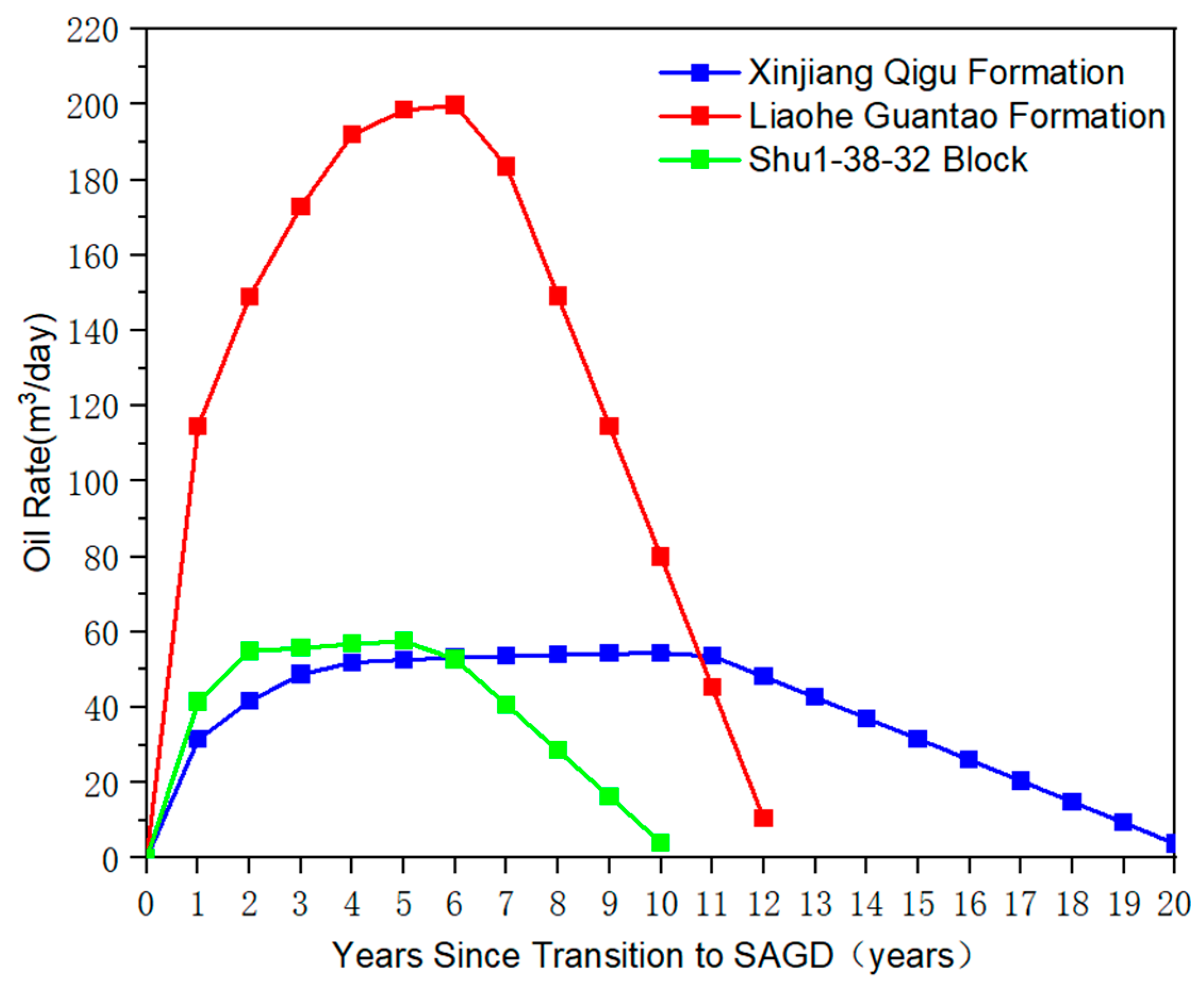
| Parameter | Xinjiang Qigu Formation | Liaohe Guantao Formation | Shu 1-38-32 Block |
|---|---|---|---|
| Burial Depth (m) | 150–500 | 515–720 | 875–1015 |
| Porosity | 0.302 | 0.363 | 0.25 |
| Oil Saturation (%) | 0.73 | 0.69 | 0.52 |
| Permeability (mD) | 2800 | 5540 | 1335 |
| Pay Zone Thickness (m) | 38 | 77 | 44 |
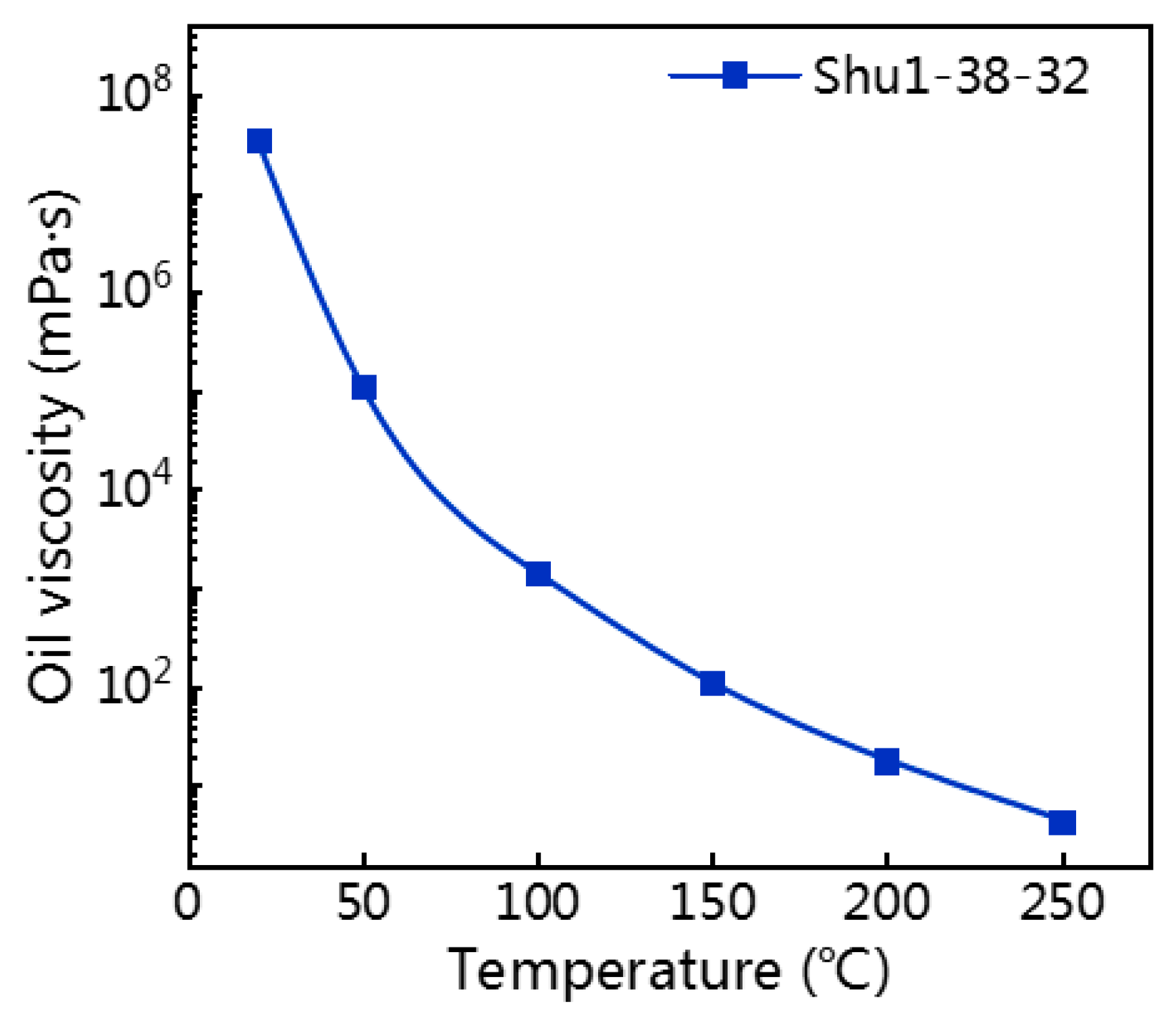
| Initial Crude Oil Viscosity (mPa·s) | 182,000 | 231,900 | 347,286 |
| Crude Oil Viscosity at Steam Temp (mPa·s) | 14.2 | 4.1 | 4.2 |
| SAGD Operating Pressure (MPa) | 1.25 | 5.4 | 4 |
| Reservoir Parameter of Shu 1-38-32 | |
|---|---|
| Crude Oil Viscosity, mPa·s | 109,269 |
| Crude Oil Density at 20 °C | 0.96 |
| Reservoir Depth, m | 875–1015 |
| Continuous Pay Zone Thickness, m | 44 |
| Porosity | 0.25 |
| Permeability, 10−3 m2 (i.e., mD) | 1335 |
| Oil Saturation | 0.65 |
| Net-to-Gross Ratio | 0.8 |
| Year | Annual Steam Injection (104 t) | Annual C6 Injection (104 t) | Annual Liquid Production (104 t) | Annual Oil Production (104 t) | Annual Water Production (104 t) | Water Cut (%) | Oil-Steam Ratio | Steam-Oil Ratio | Recovery Factor (%) |
|---|---|---|---|---|---|---|---|---|---|
| 1 | 39.26 | 0.38 | 44.17 | 6.64 | 37.53 | 0.85 | 0.17 | 1.2 | 32.5 |
| 2 | 43.97 | 1.36 | 54.92 | 10.32 | 44.6 | 0.81 | 0.23 | 1.2 | 39.3 |
| 3 | 43.97 | 1.36 | 55.84 | 10.94 | 44.9 | 0.81 | 0.24 | 1.2 | 46.1 |
| 4 | 43.97 | 1.36 | 57.87 | 9.42 | 48.45 | 0.84 | 0.21 | 1.3 | 52.3 |
| 5 | 43.97 | 1.36 | 56.62 | 7.73 | 48.89 | 0.86 | 0.18 | 1.2 | 57.3 |
| 6 | 43.97 | 1.36 | 58.44 | 5.82 | 52.62 | 0.9 | 0.13 | 1.3 | 61.2 |
| 7 | 26.38 | 0.51 | 37.84 | 3.35 | 34.49 | 0.91 | 0.13 | 1.4 | 63.3 |
| Total | 285.51 | 7.64 | 370.7 | 53.77 | – | – | 0.19 | 1.3 | – |
Disclaimer/Publisher’s Note: The statements, opinions and data contained in all publications are solely those of the individual author(s) and contributor(s) and not of MDPI and/or the editor(s). MDPI and/or the editor(s) disclaim responsibility for any injury to people or property resulting from any ideas, methods, instructions or products referred to in the content. |
© 2025 by the authors. Licensee MDPI, Basel, Switzerland. This article is an open access article distributed under the terms and conditions of the Creative Commons Attribution (CC BY) license (https://creativecommons.org/licenses/by/4.0/).
Share and Cite
Zhou, Y.; Huang, S.; Yang, S.; Jiang, Q.; Wang, Z.; Wang, H.; Yue, L.; Ma, T. Optimizing Solvent-Assisted SAGD in Deep Extra-Heavy Oil Reservoirs: Mechanistic Insights and a Case Study in Liaohe. Energies 2025, 18, 3599. https://doi.org/10.3390/en18143599
Zhou Y, Huang S, Yang S, Jiang Q, Wang Z, Wang H, Yue L, Ma T. Optimizing Solvent-Assisted SAGD in Deep Extra-Heavy Oil Reservoirs: Mechanistic Insights and a Case Study in Liaohe. Energies. 2025; 18(14):3599. https://doi.org/10.3390/en18143599
Chicago/Turabian StyleZhou, Ying, Siyuan Huang, Simin Yang, Qi Jiang, Zhongyuan Wang, Hongyuan Wang, Lifan Yue, and Tengfei Ma. 2025. "Optimizing Solvent-Assisted SAGD in Deep Extra-Heavy Oil Reservoirs: Mechanistic Insights and a Case Study in Liaohe" Energies 18, no. 14: 3599. https://doi.org/10.3390/en18143599
APA StyleZhou, Y., Huang, S., Yang, S., Jiang, Q., Wang, Z., Wang, H., Yue, L., & Ma, T. (2025). Optimizing Solvent-Assisted SAGD in Deep Extra-Heavy Oil Reservoirs: Mechanistic Insights and a Case Study in Liaohe. Energies, 18(14), 3599. https://doi.org/10.3390/en18143599