
Biomass-Derived Catalysts with Dual Functions for Electrochemical Water Splitting


Abstract
1. Introduction
2. Experimental Section
2.1. Materials
2.2. Preparation of NiFe-Based Carbonaceous Precursor
2.3. Heat Treatment of the Precursor Under Different Pyrolysis Conditions
2.4. Electrochemical Testing
2.5. Characterization and Analytical Methods
3. Results and Discussion
3.1. Selection of Bifunctional Catalysts and Determination of Pyrolysis Conditions
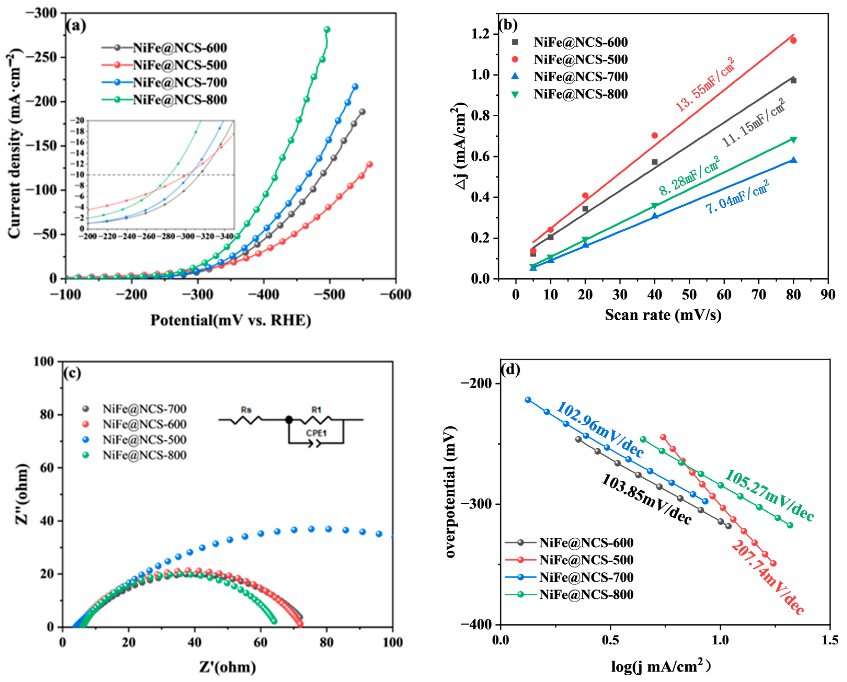
3.1.1. HER Performance of Bifunctional Catalysts
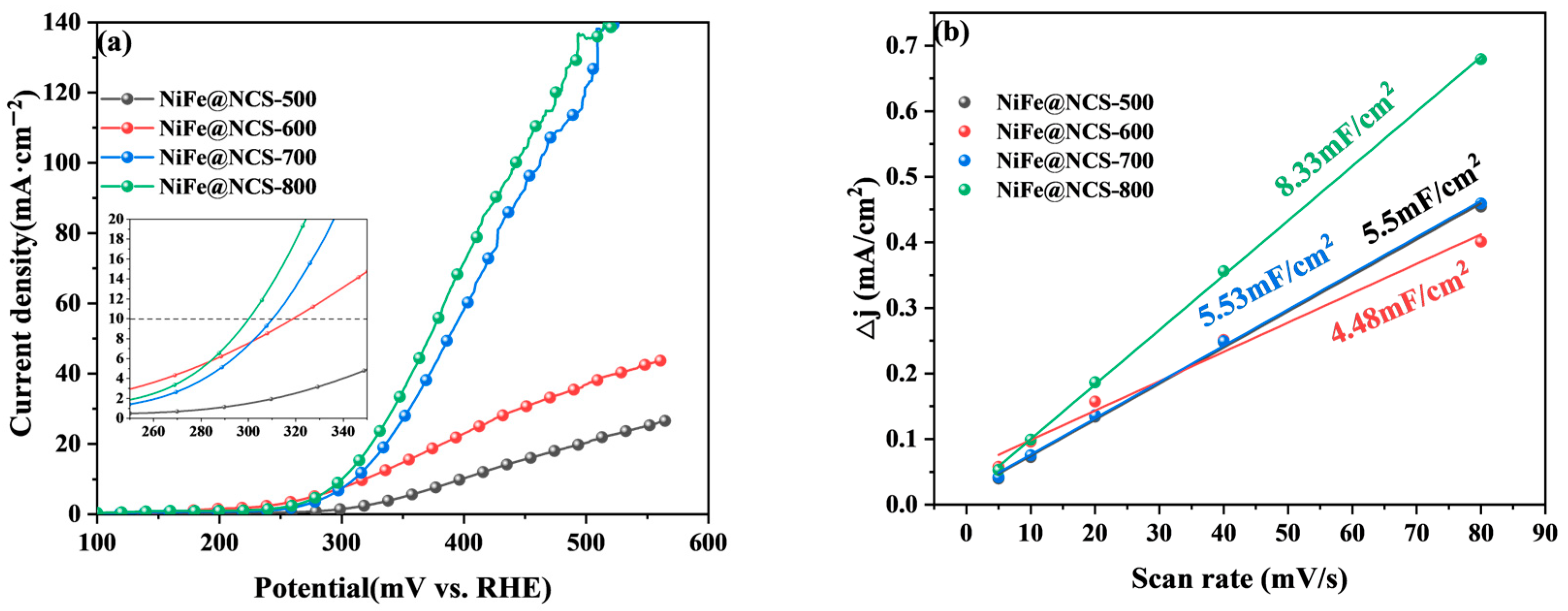
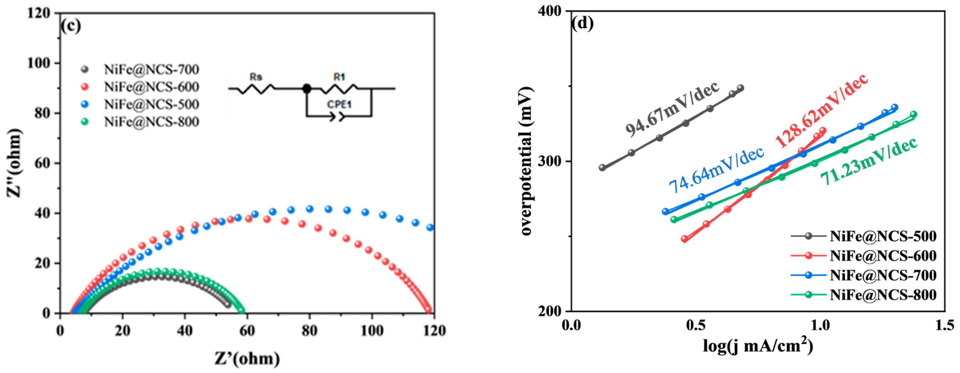
3.1.2. OER Performance of Bifunctional Catalysts
3.2. Analysis of Structural Morphology and Metallic States
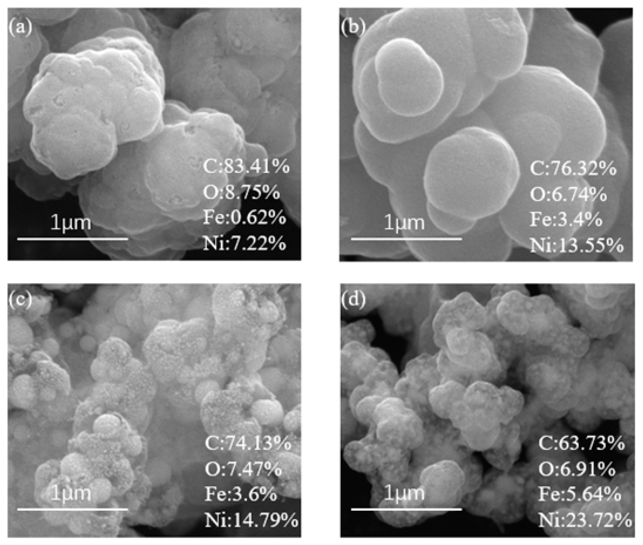
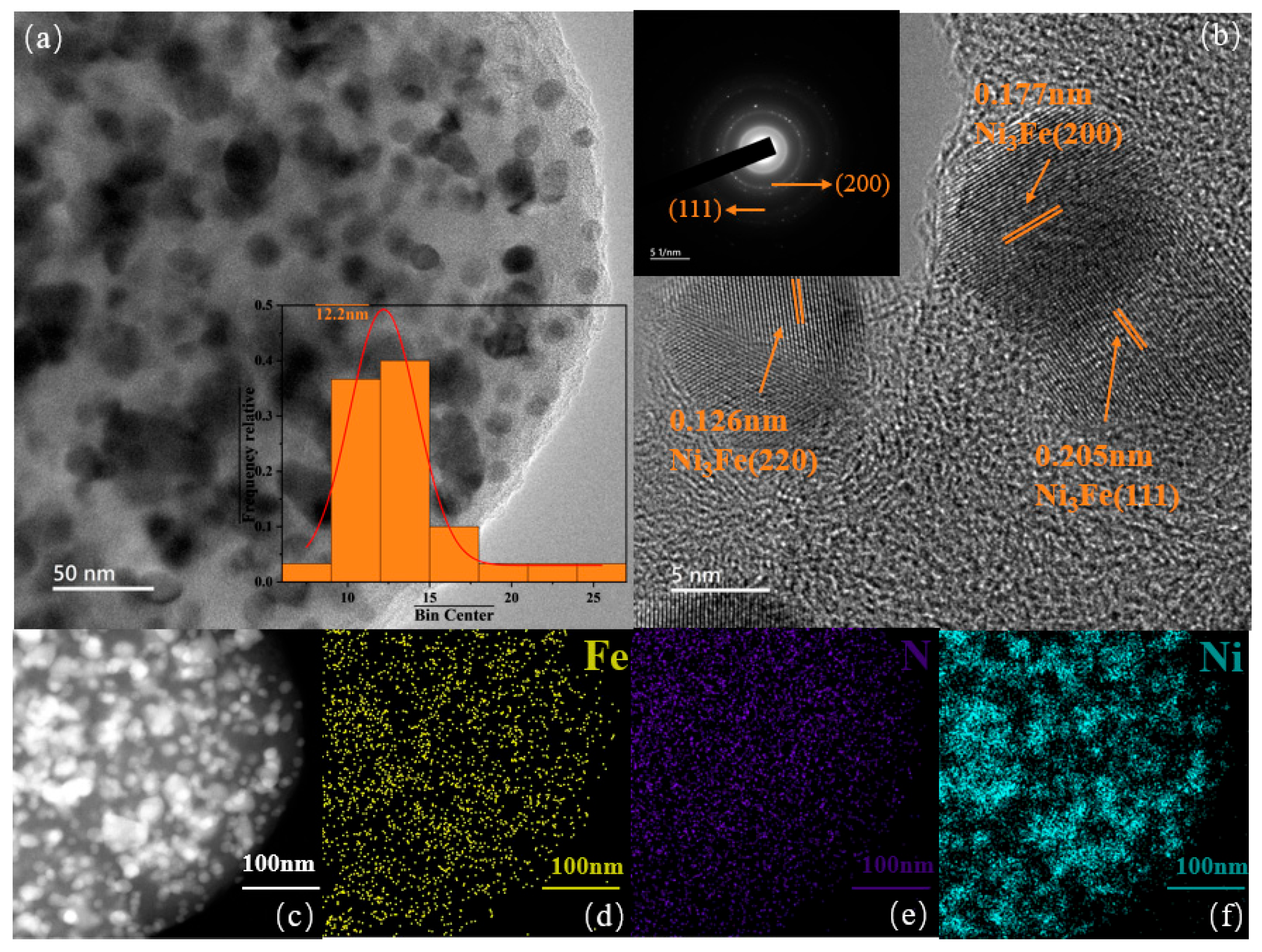
3.2.1. Morphology Analysis of Bifunctional Catalyst
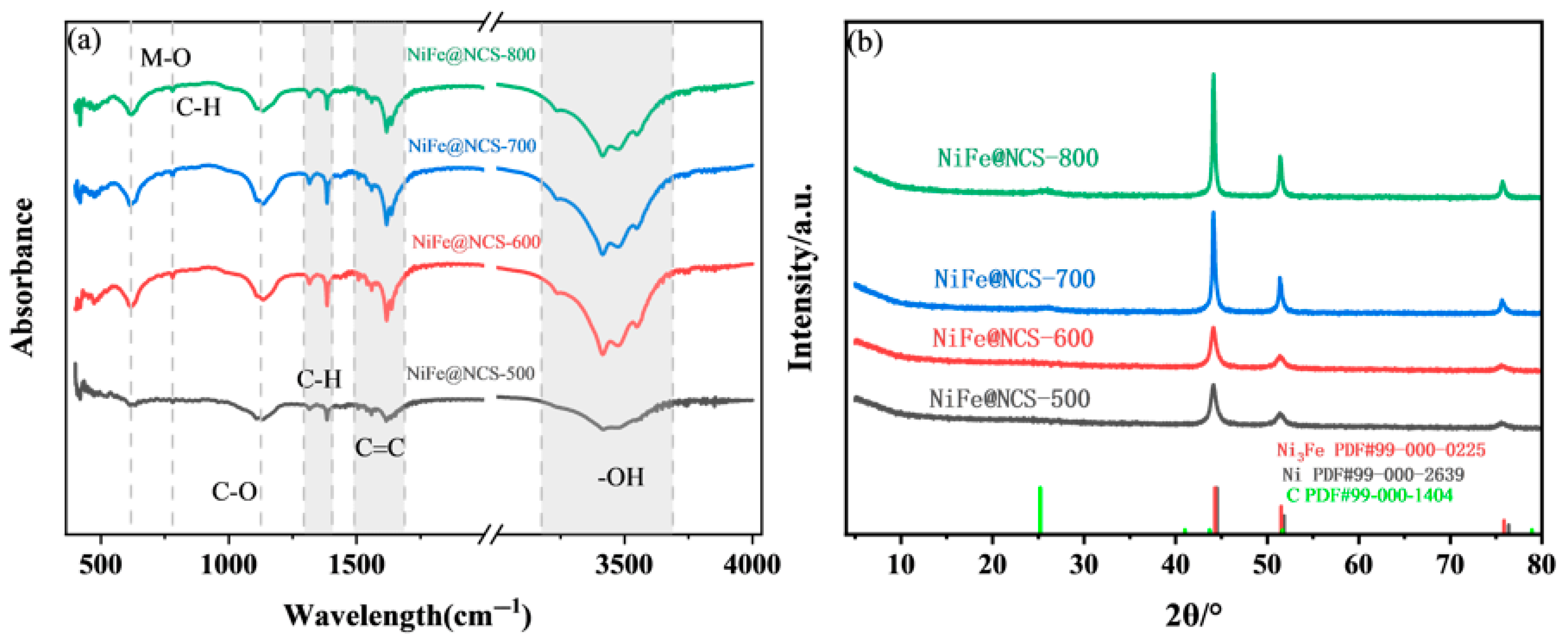
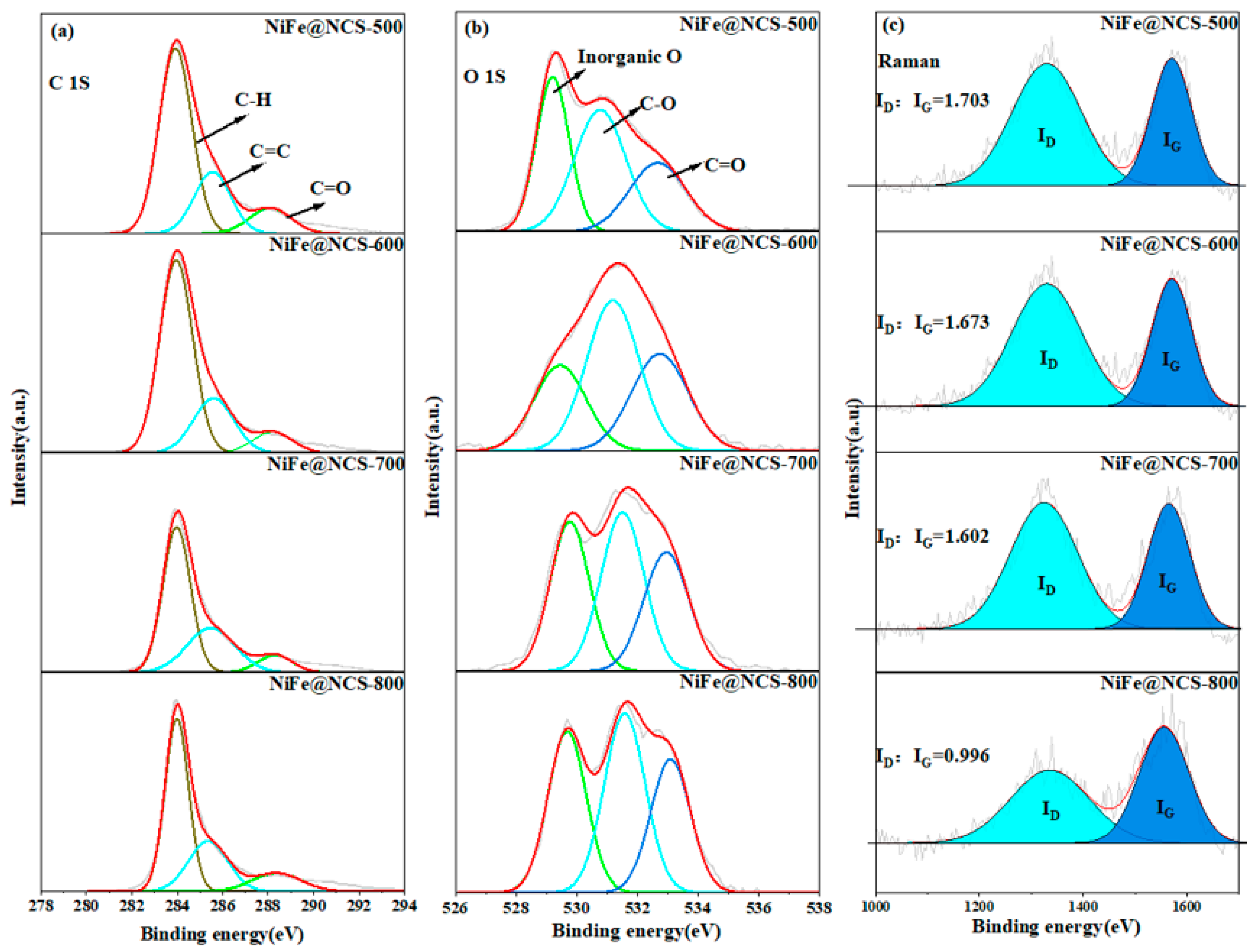
3.2.2. Metallic States Analysis of Bifunctional Catalysts
3.3. Mechanism Analysis of Bifunctional Catalysts
4. Conclusions
Supplementary Materials
Author Contributions
Funding
Data Availability Statement
Acknowledgments
Conflicts of Interest
References
- Alptekin, F.M.; Celiktas, M.S. Review on Catalytic Biomass Gasification for Hydrogen Production as a Sustainable Energy Form and Social, Technological, Economic, Environmental, and Political Analysis of Catalysts. ACS Omega 2022, 7, 24918–24941. [Google Scholar] [CrossRef]
- Henrique, A.; Biljana, S.; Sandra, G.; Diogo, M.F.S. The Current State of Transition Metal-Based Electrocatalysts (Oxides, Alloys, POMs, and MOFs) for Oxygen Reduction, Oxygen Evolution, and Hydrogen Evolution Reactions. Front. Energy Res. 2024, 12, 1373522. [Google Scholar]
- Johnson, D.; Pranada, E.; Yoo, R.; Uwadiunor, E.; Ngozichukwu, B.; Djire, A. Review and Perspective on Transition Metal Electrocatalysts toward Carbon-Neutral Energy. Energy Fuels 2023, 37, 1545–1576. [Google Scholar] [CrossRef]
- Biggins, F.; Kataria, M.; Roberts, D.; Brown, S. Green Hydrogen Investments: Investigating the Option to Wait. Energy 2022, 241, 122842. [Google Scholar] [CrossRef]
- Kazemi, A.; Manteghi, F.; Tehrani, Z. Metal Electrocatalysts for Hydrogen Production in Water Splitting. ACS Omega 2024, 9, 7310–7335. [Google Scholar] [CrossRef] [PubMed]
- Perumal, S.; Pokhrel, I.; Muhammad, U.; Shao, X.; Han, Y.; Kim, M.; Lee, H. Recent Advances in Electrochemical Water Splitting Electrocatalysts: Categorization by Parameters and Catalyst Types. ACS Mater. Lett. 2024, 6, 3625–3666. [Google Scholar] [CrossRef]
- Zhang, R.; Wang, X.; Yu, S.; Wen, T.; Zhu, X.; Yang, F.; Sun, X.; Wang, X.; Hu, W. Ternary NiCo2Px Nanowires as Ph-Universal Electrocatalysts for Highly Efficient Hydrogen Evolution Reaction. Adv. Mater. 2016, 29, 1605502. [Google Scholar] [CrossRef]
- Guo, P.; Cao, S.; Wang, Y.; Lu, X.; Zhang, Y.; Xin, X.; Chi, X.; Yu, X.; Tojiboyev, I.; Salari, H.; et al. Surface Self-Reconstruction of Telluride Induced by in-Situ Cathodic Electrochemical Activation for Enhanced Water Oxidation Performance. Appl. Catal. B-Environ. 2022, 310, 121355. [Google Scholar] [CrossRef]
- Liu, D.; Yang, Y.; Zhang, J.; Wang, L.; Ma, Z.; Ren, L.; Wang, J.; Xue, B.; Li, F. Improved OER Catalytic Performance of NiFe-LDH with Hydrothermal Carbonization Microspheres. J. Alloys Compd. 2023, 941, 168994. [Google Scholar] [CrossRef]
- Liu, L.; Li, H.; Jiang, S.; Zhao, Q.; Jiang, T. Design of High-Performance Transition Metal Sulfide Electrode Materials and Its Application in Supercapacitors. J. Power Sources 2024, 606, 234560. [Google Scholar] [CrossRef]
- Chen, H.; Jiang, H.; Cao, X.; Zhang, Y.; Zhang, X.; Qiao, S. Castoff Derived Biomass—Carbon Supported MoS2 Nanosheets for Hydrogen Evolution Reaction. Mater. Chem. Phys. 2020, 252, 123244. [Google Scholar] [CrossRef]
- Yang, G.; Zhang, Y.; Liu, J.; Wang, M.; Gu, C.; Li, J. In-Situ Growth of Ni-CoSe2 on Biomass-Derived Carbon Tubes as an Efficient Electrocatalyst for Overall Water Splitting. Int. J. Hydrog. Energy 2022, 47, 38920–38929. [Google Scholar] [CrossRef]
- Liu, G.; Wang, B.; Ding, P.; Ye, Y.; Wei, W.; Zhu, W.; Xu, L.; Xia, J.; Li, H. Reactable Ionic Liquid in Situ-Induced Synthesis of Fe3O4 Nanoparticles Modified N-Doped Hollow Porous Carbon Microtubes for Boosting Multifunctional Electrocatalytic Activity. J. Alloys Compd. 2019, 47, 849–858. [Google Scholar] [CrossRef]
- Li, G.; Wang, J.; Yu, J.; Liu, H.; Cao, Q.; Du, J.; Zhao, L.; Jia, J.; Liu, H.; Zhou, W. Ni-Ni3P Nanoparticles Embedded into N, P-Doped Carbon on 3D Graphene Frameworks Via in Situ Phosphatization of Saccharomycetes with Multifunctional Electrodes for Electrocatalytic Hydrogen Production and Anodic Degradation. Appl. Catal. B Environ. 2020, 261, 118147. [Google Scholar] [CrossRef]
- Ji, X.; Lin, Y.; Zeng, J.; Ren, Z.; Lin, Z.; Mu, Y.; Qiu, Y.; Yu, J. Graphene/MoS2/FeCoNi(OH)X and Graphene/MoS2/FeCoNiPx Multilayer-Stacked Vertical Nanosheets on Carbon Fibers for Highly Efficient Overall Water Splitting. Nat. Commun. 2021, 12, 1380. [Google Scholar] [CrossRef] [PubMed]
- Cui, X.; Ren, P.; Deng, D.; Deng, J.; Bao, X. Single Layer Graphene Encapsulating Non-Precious Metals as High-Performance Electrocatalysts for Water Oxidation. Energy Environ. Sci. 2016, 9, 123–129. [Google Scholar] [CrossRef]
- Xu, Z.; Wu, Z.; Chi, J.; Lei, E.; Liu, Y.; Yin, Y.; Yang, Z.; Ma, C.; Li, W.; Luo, S.; et al. Soft-Template Hydrothermal Synthesis of N and B Co-Doped Walnut-Shaped Porous Carbon Spheres with Hydrophilic Surfaces for Supercapacitors. Appl. Surf. Sci. 2023, 638, 158016. [Google Scholar] [CrossRef]
- Lee, J.; Son, N.; Shin, J.; Pandey, S.; Joo, S.W.; Kang, M. Highly Efficient Hydrogen Evolution Reaction Performance and Long-Term Stability of Spherical Ni100-XFex Alloy Grown Directly on a Carbon Paper Electrode. J. Alloys Compd. 2021, 869, 159265. [Google Scholar] [CrossRef]
- Lou, Q.; Zhong, S.; Li, T.; Ling, S. Preparation and Oxygen-Evolution-Reaction Performance of Sulphur-Doped Flower-Like Nife-Based Composites Supported on Biomass Porous Carbon. Dig. J. Nanomater. Biostruct. 2024, 19, 693–705. [Google Scholar] [CrossRef]
- Wang, Q.; Fei, Z.; Shen, D.; Cheng, C.; Dyson, P.J. Ginkgo Leaf-Derived Carbon Supports for the Immobilization of Iron/Iron Phosphide Nanospheres for Electrocatalytic Hydrogen Evolution. Small 2024, 20, e2309830. [Google Scholar] [CrossRef]
- Liu, Y.; Zhou, L.; Liu, S.; Li, S.; Zhou, J.; Li, X.; Chen, X.; Sun, K.; Li, B.; Jiang, J.; et al. Fe, N-Inducing Interfacial Electron Redistribution in NiCo Spinel on Biomass-Derived Carbon for Bi-Functional Oxygen Conversion. Angew. Chem. Int. Ed. Engl. 2024, 63, e202319983. [Google Scholar] [CrossRef] [PubMed]
- Zang, Y.; Lu, D.-Q.; Wang, K.; Li, B.; Peng, P.; Lan, Y.-Q.; Zang, S.-Q. A Pyrolysis-Free Ni/Fe Bimetallic Electrocatalyst for Overall Water Splitting. Nat. Commun. 2023, 14, 1792. [Google Scholar] [CrossRef] [PubMed]
- Gan, W.; Wu, L.; Wang, Y.; Gao, H.; Gao, L.; Xiao, S.; Liu, J.; Xie, Y.; Li, T.; Li, J. Carbonized Wood Decorated with Cobalt-Nickel Binary Nanoparticles as a Low-Cost and Efficient Electrode for Water Splitting. Adv. Funct. Mater. 2021, 31, 2010951. [Google Scholar] [CrossRef]
- Van, C.H.; Ngoc, D.K.; Gomes, V.G. Hybrid Ni/NiO Composite with N-Doped Activated Carbon from Waste Cauliflower Leaves: A Sustainable Bifunctional Electrocatalyst for Efficient Water Splitting. Carbon 2020, 157, 515–524. [Google Scholar]
- Liu, D.; Liu, J.; Wang, L.; Ma, Z.; Xing, J.; Yang, Y.; Xue, B.; Li, F. Enhanced Bifunctional Electrocatalytic Performance of NiFe-Layered Double Hydroxide Activated by Ultrasonic-Assisted Loading of Pd Nanoclusters. Int. J. Hydrog. Energy 2024, 49, 152–168. [Google Scholar] [CrossRef]
- Mirshokraee, S.A.; Muhyuddin, M.; Orsilli, J.; Berretti, E.; Capozzoli, L.; Lavacchi, A.; Vecchio, C.L.; Baglio, V.; Galli, A.; Zaffora, A.; et al. Mono-, Bi- and Tri-Metallic Platinum Group Metal-Free Electrocatalysts for Hydrogen Evolution Reaction Following a Facile Synthetic Route. Ind. Chem. Mater. 2023, 1, 343–359. [Google Scholar] [CrossRef]
- Maniatis, I.; Charalampopoulos, G.; Paloukis, F.; Daletou, M.K. Optimizing Fe-N-C Electrocatalysts for Pemfcs: Influence of Constituents and Pyrolysis on Properties and Performance. Catalysts 2024, 14, 780–799. [Google Scholar] [CrossRef]
- Xu, Q.; Tang, Y.; Zhai, L.; Chen, Q.; Jiang, D. Pyrolysis of Covalent Organic Frameworks: A General Strategy for Template Converting Conventional Skeletons into Conducting Microporous Carbons for High-Performance Energy Storage. Chem. Commun. 2017, 53, 11690–11693. [Google Scholar] [CrossRef] [PubMed]
- Zhao, G.; Rui, K.; Dou, S.X.; Sun, W. Heterostructures for Electrochemical Hydrogen Evolution Reaction: A Review. Adv. Funct. Mater. 2018, 28, 1803291. [Google Scholar] [CrossRef]
- Huang, Z.-H.; Liu, T.-Y.; Song, Y.; Li, Y.; Liu, X.-X. Balancing the Electrical Double Layer Capacitance and Pseudocapacitance of Hetero-Atom Doped Carbon. Nanoscale 2017, 9, 13119–13127. [Google Scholar] [CrossRef]
- Ruan, J.; Dou, T.; Zhang, M.; Shao, W.; Chen, Z.; Guo, H.; Wang, J.; Wei, W.; Qiao, W. Tailored Design of 2D Mof Derived Carbon Boosting the Low Temperature Plasma Catalysis for Water Treatment: The Role of Graphitization and Hierarchical Porous Structure. Chem. Eng. J. 2023, 470, 144316. [Google Scholar] [CrossRef]
- Bose, P.; Bid, S.; Pradhan, S.K.; Pal, M.; Chakravorty, D. X-ray characterization of nanocrystalline Ni3Fe. J. Alloys Compd. 2002, 343, 192–198. [Google Scholar] [CrossRef]
- Zhang, X.; Xu, H.; Li, X.; Li, Y.; Yang, T.; Liang, Y. Facile Synthesis of Nickel–Iron/Nanocarbon Hybrids as Advanced Electrocatalysts for Efficient Water Splitting. ACS Catal. 2015, 6, 580–588. [Google Scholar] [CrossRef]
- Yin, S.; Yi, H.; Liu, M.; Yang, J.; Yang, S.; Zhang, B.-W.; Chen, L.; Cheng, X.; Huang, H.; Huang, R.; et al. An in Situ Exploration of How Fe/N/C Oxygen Reduction Catalysts Evolve During Synthesis under Pyrolytic Conditions. Nat. Commun. 2024, 15, 6229–6238. [Google Scholar] [CrossRef]
- Huang, H.; Zhou, S.; Yu, C.; Huang, H.; Zhao, J.; Dai, L.; Qiu, J. Rapid and Energy-Efficient Microwave Pyrolysis for High-Yield Production of Highly-Active Bifunctional Electrocatalysts for Water Splitting. Energy Environ. Sci. 2020, 13, 545–553. [Google Scholar] [CrossRef]
- Wang, Y.; Jiang, K.; Zhang, H.; Zhou, T.; Wang, J.; Wei, W.; Yang, Z.; Sun, X.; Cai, W.-B.; Zheng, G. Bio-Inspired Leaf-Mimicking Nanosheet/Nanotube Heterostructure as a Highly Efficient Oxygen Evolution Catalyst. Adv. Sci. 2015, 2, 1500003. [Google Scholar] [CrossRef]
- Du, S.; Ren, Z.; Zhang, J.; Wu, J.; Xi, W.; Zhu, J.; Fu, H. Co3O4 Nanocrystal Ink Printed on Carbon Fiber Paper as a Large-Area Electrode for Electrochemical Water Splitting. Chem. Commun. 2015, 51, 8066–8069. [Google Scholar] [CrossRef] [PubMed]
- Shi, H.; Zhao, G. Water oxidation on spinel NiCo2O4 nanoneedles anode: Microstructures, specific surface character, and the enhanced electrocatalytic performance. J. Phys. Chem. C 2014, 118, 25939e46. [Google Scholar] [CrossRef]
- Liang, Y.; Liu, Q.; Asiri, A.M.; Sun, X.; He, Y. Nickel-Iron Foam as a Three-Dimensional Robust Oxygen Evolution Electrode with High Activity. Int. J. Hydrog. Energy 2015, 40, 13258–13263. [Google Scholar] [CrossRef]
- Liang, H.; Meng, F.; Caban-Acevedo, M.; Li, L.; Forticaux, A.; Xiu, L.; Wang, Z.; Jin, S. Hydrothermal Continuous Flow Synthesis and Exfoliation of NiCo Layered Double Hydroxide Nanosheets for Enhanced Oxygen Evolution Catalysis. Nano Lett. 2015, 15, 1421–1427. [Google Scholar] [CrossRef]
- Ke, W.; Li, J.; Yang, G.; Liang, P.; Zhang, C. Study on the Electrocatalytic Oxygen and Hydrogen Evolution Performance of Mo-Droped La0.9Sr0.2Co1-xMoxO3-δ. Mater. Res. Appl. 2024, 18, 225–234. [Google Scholar]
- Zhao, Z.; Zhang, S.; Jin, M.; Zhang, H. Pt Nanoparticle Dispersed Ni(OH)2 Nanosheets Via a Pulsed Laser Deposition Method Efficiently Enhanced Hydrogen Evolution Reaction Performance in Alkaline Conditions. RSC Adv. 2023, 13, 13840–13844. [Google Scholar] [CrossRef] [PubMed]
- Li, J.; Yan, M.; Zhou, X.; Huang, Z.-Q.; Xia, Z.; Chang, C.-R.; Ma, Y.; Qu, Y. Mechanistic Insights on Ternary Ni2−XCoxP for Hydrogen Evolution and Their Hybrids with Graphene as Highly Efficient and Robust Catalysts for Overall Water Splitting. Adv. Funct. Mater. 2016, 26, 6785–6796. [Google Scholar] [CrossRef]


| Thermophysical Properties | NiFe@NCS-500 | NiFe@NCS-600 | NiFe@NCS-700 | NiFe@NCS-800 |
|---|---|---|---|---|
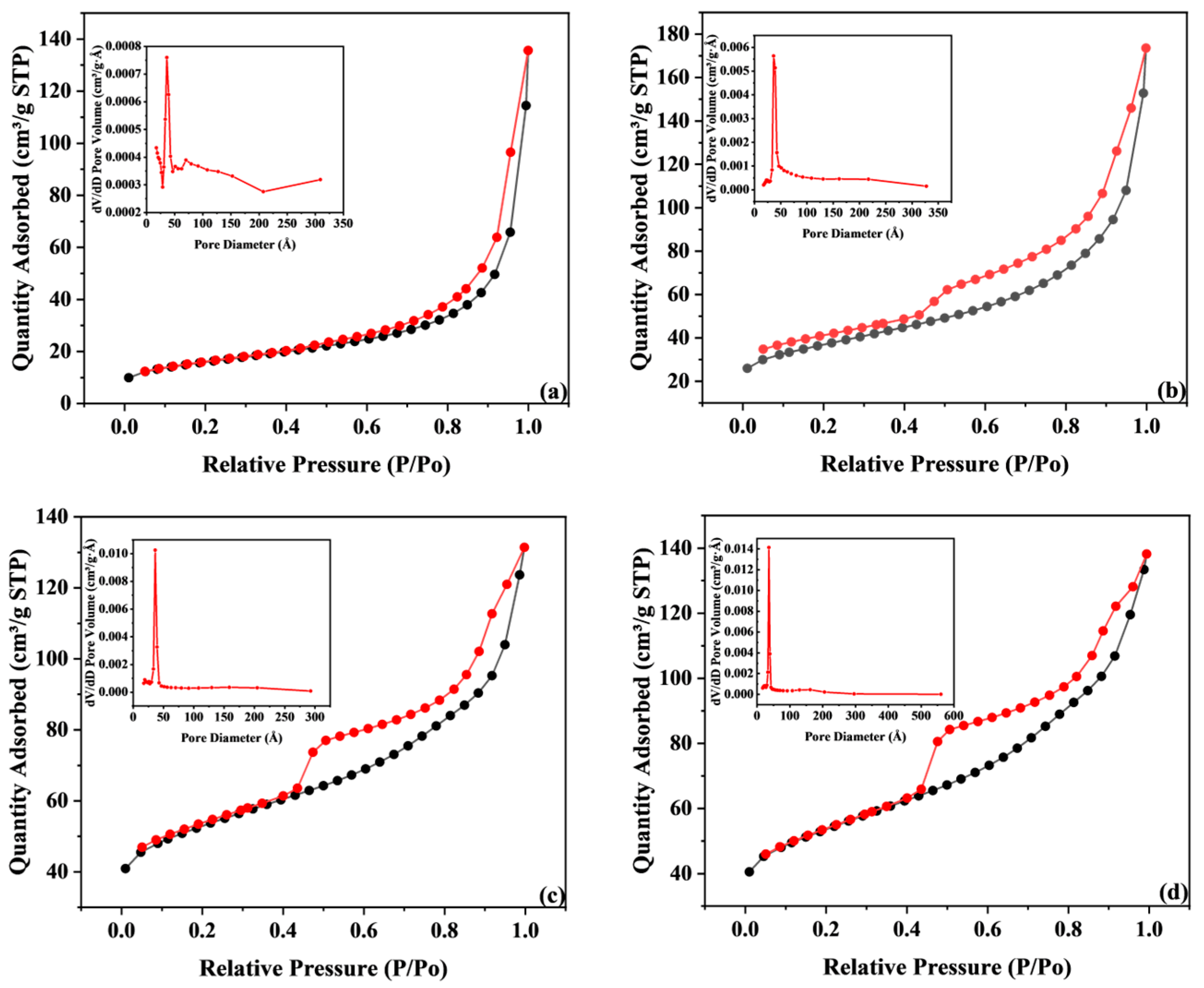
| BET Surface Area (m2·g−1) | 55.89 | 131.36 | 191.26 | 190.94 |
| Pore volume (cm3·g−1) | 0.145 | 0.202 | 0.143 | 0.178 |
| Pore Size (Å) | 115.41 | 81.27 | 58.26 | 58.87 |
Disclaimer/Publisher’s Note: The statements, opinions and data contained in all publications are solely those of the individual author(s) and contributor(s) and not of MDPI and/or the editor(s). MDPI and/or the editor(s) disclaim responsibility for any injury to people or property resulting from any ideas, methods, instructions or products referred to in the content. |
© 2025 by the authors. Licensee MDPI, Basel, Switzerland. This article is an open access article distributed under the terms and conditions of the Creative Commons Attribution (CC BY) license (https://creativecommons.org/licenses/by/4.0/).
Share and Cite
Zhu, W.; Zhang, X.; Zhang, Q.; Chen, L.; Zhuang, X.; Ma, L. Biomass-Derived Catalysts with Dual Functions for Electrochemical Water Splitting. Energies 2025, 18, 3592. https://doi.org/10.3390/en18143592
Zhu W, Zhang X, Zhang Q, Chen L, Zhuang X, Ma L. Biomass-Derived Catalysts with Dual Functions for Electrochemical Water Splitting. Energies. 2025; 18(14):3592. https://doi.org/10.3390/en18143592
Chicago/Turabian StyleZhu, Wangchuang, Xinghua Zhang, Qi Zhang, Lungang Chen, Xiuzheng Zhuang, and Longlong Ma. 2025. "Biomass-Derived Catalysts with Dual Functions for Electrochemical Water Splitting" Energies 18, no. 14: 3592. https://doi.org/10.3390/en18143592
APA StyleZhu, W., Zhang, X., Zhang, Q., Chen, L., Zhuang, X., & Ma, L. (2025). Biomass-Derived Catalysts with Dual Functions for Electrochemical Water Splitting. Energies, 18(14), 3592. https://doi.org/10.3390/en18143592