
A Comprehensive Review on Studies of Flow Characteristics in Horizontal Tube Falling Film Heat Exchangers

Abstract
1. Introduction
2. Review Methods
3. Liquid Film Thickness
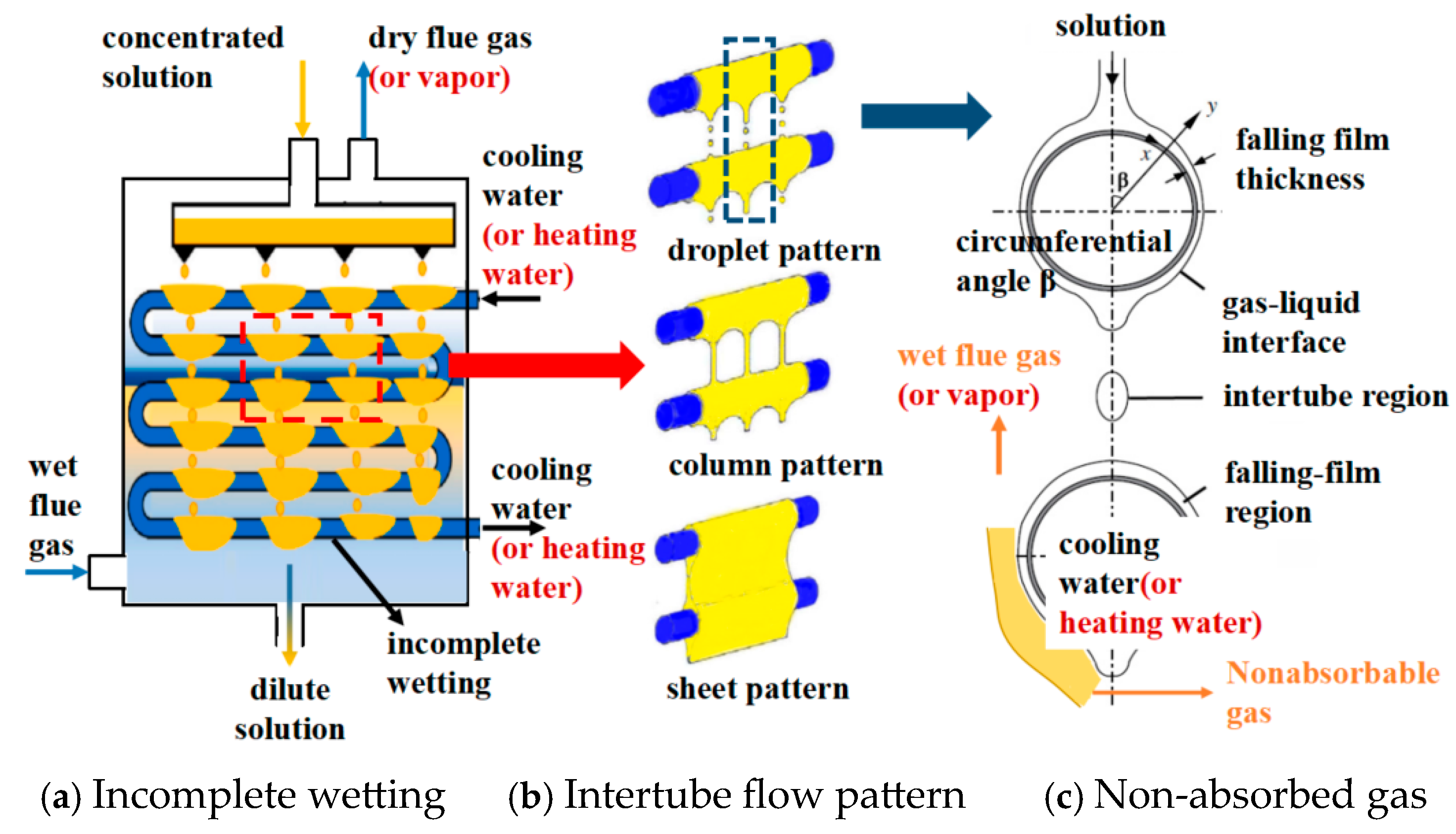
4. Surface Wettability
5. Inter-Tube Flow Patterns

| Droplet→ Droplet-Column | Droplet-Column→ Column | Column→ Column-Sheet | Column-Sheet→ Sheet | |
|---|---|---|---|---|
| Equation (9) | ||||
| Equation (10) | ||||
| Equation (11) | ||||
| Equation (12) |
6. Optimization Strategy and Design Suggestions
- (1)
- Collaborative Optimization Design with Multiple Parameters
- (2)
- Optimization of Materials and Surface Treatment
- (3)
- Strengthen monitoring and intelligent control
7. Conclusions
- (1)
- The experimental methods are more intuitive and accurate, evolving from contact-based techniques to non-contact-based ones. The numerical simulations can analyze the internal field distribution and local features, and the accuracy of these models has improved significantly. They have advanced from two-dimensional to three-dimensional models, from single-row to multi-row tube configurations, and from models that neglect inter-tube absorption processes to those that consider more complex factors such as incomplete wetting, inter-tube flow patterns, and gas flow characteristics. Current research typically combines experimental and numerical methods to study flow performance.
- (2)
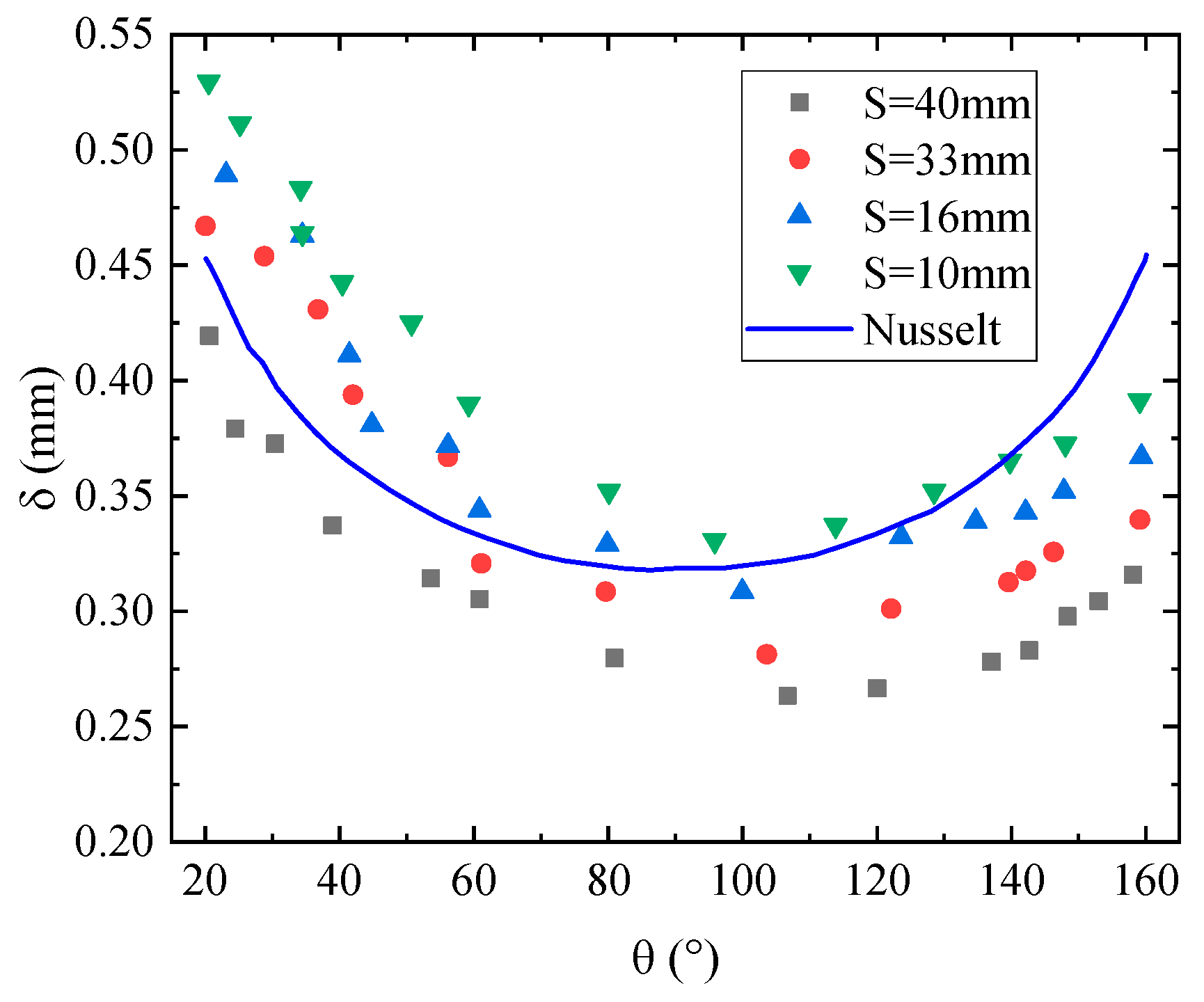
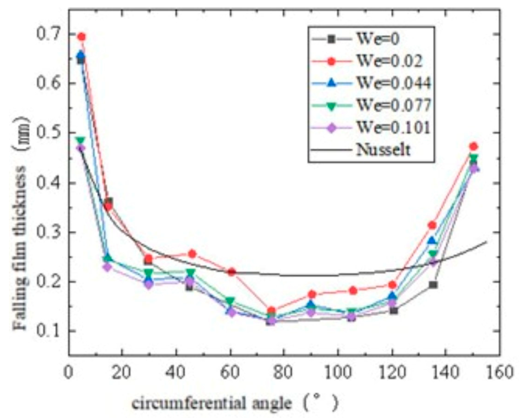
- The circumferential distribution of liquid film thickness has been quantitatively characterized using predictive correlation equations, which have evolved from considering only fluid properties and inertial forces to incorporating additional factors such as tube diameter, inter-tube spacing, buoyancy, and gas flow characteristics. In contrast, the axial distribution of the liquid film thickness is still largely in the qualitative analysis stage.
- (3)
- Research on the wettability characteristics has evolved from studying the two-dimensional circumferential wettability of smooth tubes to considering the three-dimensional circumferential and axial wettability. Several approaches have been explored to enhance the wettability ratio, including the choice of tube material, surface treatments, and the use of additives.
- (4)
- The predictive correlation equations for the critical Reynolds number of inter-tube flow patterns have become more sophisticated. Initially, these equations considered only fluid properties, but more recently, they have expanded to include factors such as fluid properties, tube diameter, inter-tube spacing, and gas flow characteristics.
- (1)
- In the axial distribution of the liquid film thickness, further expansion of the research scope to include a broader range of operational factors is needed to achieve a more comprehensive quantitative description.
- (2)
- The studies on the wettability characteristics are primarily in the qualitative analysis phase, with limited development of quantitative correlation equations for wettability. Moreover, in recent years, HTFFHEs have gained attention to utilize deep residual heat from combustion equipment through solution absorption processes; the flue gas composition and flow velocity are critical factors influencing inter-tube flow pattern transitions. Further in-depth studies are needed on the multi-factor quantitative characterization of wettability and the relationship between wettability ratio and heat/mass transfer performance.
- (3)
- While the accuracy of these predictive equations for the critical Reynolds number has improved, their applicability is still limited to a narrower range of fluid types, and the scope of structural and operational parameters needs to be further expanded.
- (1)
- There is a lack of widely recognized predictive correlations for flow characteristics such as liquid film thickness and wettability, as well as predictive correlations for heat and mass transfer coefficients.
- (2)
- Reinforced tubes have received attention and application, and it is necessary to study and predict the flow pattern transition, liquid film thickness, and wettability of different solutions on reinforced tubes.
- (3)
- The current development of predictive correlation equations for flow characteristics primarily focuses on incorporating more influencing factors. However, the applicability of different correlations remains limited, necessitating the proposal of universal predictive models.
- (4)
- Based on the existing massive data, it is possible to consider using artificial intelligence and other methods to construct a new correlation equation regarding the relationship between flow, heat and mass transfer.
Author Contributions
Funding
Data Availability Statement
Conflicts of Interest
References
- Wang, W. Research on Enhancing Heat Transfer Performance in Falling-Film Evaporation Outside Horizontal Tubes in Lithium Bromide Absorption Refrigeration System; Chang’an University: Xi’an, China, 2021. [Google Scholar]
- Gong, L.; Shen, S.; Liu, H.; Mu, X.; Chen, X. Three-dimensional heat transfer coefficient distributions in a large horizontal-tube falling film evaporator. Desalination 2014, 357, 104–116. [Google Scholar] [CrossRef]
- Ma, L. Research on the Recovery of Waste Heat from Chlor-Alkali Evaporation Section by Absorption Heat Pump; Dalian University of Technology: Dalian, China, 2004. [Google Scholar]
- Pan, Y.; Ma, S.; Wang, Y. Modeling and performance analysis of vacuum drying system based on open absorption heat pump. Sci. Technol. Eng. 2020, 20, 8568–8572. [Google Scholar]
- Zhang, H. Mechanism and Experiment Study on Water and Heat Recovery Form Low-Temperature Coal-Fired Wet Flue Gas Based on Solution Absorption Method; Shandong University: Jinan, China, 2022. [Google Scholar]
- Cheng, G.; Li, H.; Kang, S.; Zeng, R.; Zhang, G. A study of the CCHP system based on the deep utilization of low temperature flue gas. Sci. Technol. Eng. 2016, 16, 51–57. [Google Scholar]
- Shi, G.; Lin, J.; Tian, Z. Analysis of waste heat recovery from steel plant for heating by reducing return water temperature. Sci. Technol. Eng. 2021, 21, 15035–15042. [Google Scholar]
- Sehgal, S.; Alvarado, J.L.; Hassan, I.G.; Kadam, S.T. A comprehensive review of recent developments in falling-film, spray, bubble and microchannel absorbers for absorption systems. Renew. Sustain. Energy Rev. 2021, 142, 110807. [Google Scholar] [CrossRef]
- Zhao, C.-Y.; Qi, D.; Ji, W.-T.; Jin, P.-H.; Tao, W.-Q. A comprehensive review on computational studies of falling film hydrodynamics and heat transfer on the horizontal tube and tube bundle. Appl. Therm. Eng. 2022, 202, 117869. [Google Scholar] [CrossRef]
- Dai, Z.; Zhang, Y.; Wang, S.; Nawaz, K.; Jacobi, A. Falling-film heat exchangers used in desalination systems: A review. Int. J. Heat Mass Transf. 2022, 185, 122407. [Google Scholar] [CrossRef]
- Zhao, C.-Y.; Zheng, C.-M.; Wang, X.-S.; Qi, D.; Jiang, J.-M.; Ji, W.-T.; Jin, P.-H.; Tao, W.-Q. Correlations of falling film hydrodynamics and heat transfer on horizontal tubes: A review. Renew. Sustain. Energy Rev. 2024, 197, 114384. [Google Scholar] [CrossRef]
- Lin, H.-Y.; Muneeshwaran, M.; Yang, C.-M.; Nawaz, K.; Wang, C.-C. On falling film evaporator—A review of mechanisms and critical assessment of correlation on a horizontal tube bundle with updated development. Int. Commun. Heat Mass Transf. 2024, 150, 107165. [Google Scholar] [CrossRef]
- Jia, B.; Yang, L.; Politaeva, N.; Zhou, J.; Sadeghi, K. Review on droplet falling film evaporation in desalination: A focus on heat transfer enhancement of micro-nano structured surfaces. Desalination 2025, 598, 118373. [Google Scholar] [CrossRef]
- Hou, H.; Bi, Q.; Ma, H.; Wu, G. Distribution characteristics of falling film thickness around a horizontal tube. Desalination 2012, 285, 393–398. [Google Scholar] [CrossRef]
- Tan, Q. Study on Film Flow and Enhanced Heat Transfer Characteristics of Horizontal Tube; Southwest University of Science and Technology: Mianyang, China, 2018. [Google Scholar]
- Zhang, Y.; Wang, D.; Liu, Y.; Tang, M.; Zhang, S. Distribution characteristics of falling film thickness around a horizontal corrugated tube. Int. J. Heat Mass Transf. 2020, 154, 119773. [Google Scholar] [CrossRef]
- Zhao, Y. Flow Characteristics of Falling Film on Horizontal Tubes with the Action of Transverse Airflow; Shandong University: Jinan, China, 2021. [Google Scholar]
- Guo, B.; Li, H.; Guo, D. Measurement and analysis of the thickness distributions of falling liquid films around horizontal tubes. J. Eng. Thermophys. 2011, 32, 71–74. [Google Scholar]
- Xu, L.; Wang, S.; Wang, Y.; Ling, Y. Flowing state of liquid films over horizontal tubes and its influences on heat-transfer characteristics. J. Chem. Ind. Eng. 2002, 53, 555–559. [Google Scholar]
- Yu, Y.; Ma, L.; Ye, H.; Zheng, Y.; Ma, Y. Research of non-contact measurement for high viscous fluid falling film thickness on spherical series surface. Measurement 2017, 101, 1–8. [Google Scholar] [CrossRef]
- Hazuku, T.; Fukamachi, N.; Takamasa, T.; Hibiki, T.; Ishii, M. Measurement of liquid film in microchannels using a laser focus displacement meter. Exp. Fluids 2005, 38, 780–788. [Google Scholar] [CrossRef]
- Lel, V.V.; Al-Sibai, F.; Leefken, A.; Renz, U. Local thickness and wave velocity measurement of wavy films with a chromatic confocal imaging method and a fluorescence intensity technique. Exp. Fluids 2005, 39, 856–864. [Google Scholar] [CrossRef]
- Han, Y.; Shikazono, N. Measurement of the liquid film thickness in micro tube slug flow. Int. J. Heat Fluid Flow 2009, 30, 842–853. [Google Scholar] [CrossRef]
- Chen, X. Study on Falling Film Flow and Evaporative Heat Transfer Process of Seawater outside Horizontal Tubes; Dalian University of Technology: Dalian, China, 2015. [Google Scholar]
- Gstoehl, D.; Roques, J.F.; Crisinel, P.; Thome, J.R. Measurement of falling film thickness around a horizontal tube using a laser measurement technique. Heat Transf. Eng. 2004, 25, 28–34. [Google Scholar] [CrossRef]
- Chen, Z. The Thickness Measurement and Heat Transfer Experiment of Falling Film Outside the Horizontal Tube; Huazhong University of Science & Technology: Wuhan, China, 2013. [Google Scholar]
- Chen, X.; Shen, S.; Wang, Y.; Chen, J.; Zhang, J. Measurement on falling film thickness distribution around horizontal tube with laser-induced fluorescence technology. Int. J. Heat Mass Transf. 2015, 89, 707–713. [Google Scholar] [CrossRef]
- Liu, S.; Mu, X.; Shen, S.; Li, C.; Wang, B. Experimental study on the distribution of local heat transfer coefficient of falling film heat transfer outside horizontal tube. Int. J. Heat Mass Transf. 2021, 170, 121031. [Google Scholar] [CrossRef]
- Jiang, C. Analysis of Heat and Mass Transfer of LiBr Solution Falling Film Absorption in Absorber with Horizontal Tube; China University of Petroleum: Qingdao, China, 2007. [Google Scholar]
- Harikrishnan, L.; Tiwari, S.; Maiya, M. Numerical study of heat and mass transfer characteristics on a falling film horizontal tubular absorber for R-134a-DMAC. Int. J. Therm. Sci. 2011, 50, 149–159. [Google Scholar] [CrossRef]
- Rattner, A.S.; Garimella, S. Simple mechanistically consistent formulation for volume-of-fluid based computations of condensing flows. J. Heat Transf. 2014, 136, 071501. [Google Scholar] [CrossRef]
- Li, M.; Lu, Y.; Zhang, S.; Xiao, Y. A numerical study of effects of counter-current gas flow rate on local hydrodynamic characteristics of falling films over horizontal tubes. Desalination 2016, 383, 68–80. [Google Scholar] [CrossRef]
- Qiu, Q.; Zhang, X.; Quan, S.; Zhu, X.; Shen, S. 3D numerical study of the liquid film distribution on the surface of a horizontal-tube falling-film evaporator. Int. J. Heat Mass Transf. 2018, 124, 943–952. [Google Scholar] [CrossRef]
- Liu, S. Inter-Tube Flow Pattern Distribution and Outside-Tube Heat Transfer Coefficient of Horizontal Tube Falling Film; Dalian University of Technology: Dalian, China, 2021. [Google Scholar]
- Sun, F.; Xu, S.; Gao, Y. Numerical simulation of liquid falling film on horizontal circular tubes. Front. Chem. Sci. Eng. 2012, 6, 322–328. [Google Scholar] [CrossRef]
- Subramaniam, V.; Garimella, S. Numerical study of heat and mass transfer in lithium bromide-water falling films and droplets. Int. J. Refrig. 2014, 40, 211–226. [Google Scholar] [CrossRef]
- Zhao, C.-Y.; Ji, W.-T.; He, Y.-L.; Zhong, Y.-J.; Tao, W.-Q. A comprehensive numerical study on the subcooled falling film heat transfer on a horizontal smooth tube. Int. J. Heat Mass Transf. 2018, 119, 259–270. [Google Scholar] [CrossRef]
- Killion, J.D.; Garimella, S. Pendant droplet motion for absorption on horizontal tube banks. Int. J. Heat Mass Transf. 2004, 47, 4403–4414. [Google Scholar] [CrossRef]
- Li, M.; Lu, Y. Numerical and experimental study of local heat mass transfer characteristics of horizontal falling films of CaCl2 solution absorbing vapor from humid air. Int. J. Heat Mass Transf. 2020, 153, 119574. [Google Scholar] [CrossRef]
- Andberg, J.W.; Cliet, G.C. A simplified model for absorption of vapors into liquid films flowing over cooled horizontal tubes. ASHRAE Trans. 1987, 93, 2454–2463. [Google Scholar]
- Choudhury, S.K.; Hisajima, D.; Ohuchi, T.; Sakaguchi, S. Absorption of vapors into liquid films flowing over cooled horizontal tubes. ASHRAE Trans. 1993, 99, 81–89. [Google Scholar]
- Jeong, S.; Garimella, S. Falling-film and droplet mode heat and mass transfer in a horizontal tube LiBr/water absorber. Int. J. Heat Mass Transf. 2002, 45, 1445–1458. [Google Scholar] [CrossRef]
- Zhang, H.; Yin, D.; You, S.; Zheng, W.; Wei, S. Experimental investigation of heat and mass transfer in a LiBr-H2O solution falling film absorber on horizontal tubes: Comprehensive effects of tube types and surfactants. Appl. Therm. Eng. 2018, 146, 203–211. [Google Scholar] [CrossRef]
- Xie, X.; Liu, H.; He, C.; Zhang, B.; Chen, Q.; Pan, M. Deciphering the heat and mass transfer behaviors of staggered tube bundles in a closed wet cooling tower using a 3-D VOF model. Appl. Therm. Eng. 2019, 161, 114202. [Google Scholar] [CrossRef]
- Furqan, T.; Abdelnasser, M.; Muammer, K. Influence of co-current vapor flow on falling film over horizontal tube. Int. J. Therm. Sci. 2021, 159, 106614. [Google Scholar]
- Zhang, H.; Zhou, Y. Effect of wind speed on the spatial distribution of liquid film thickness outside the horizontal falling-film tube. Int. J. Heat Mass Transf. 2022, 187, 122584. [Google Scholar] [CrossRef]
- Wang, X.; Zhan, T.; Dai, S.; Zhang, G.; Wu, J.; Wu, Y. Inundation correlation research on the simulation of two-phase flow and heat transfer in a condenser. J. Phys. Conf. Ser. 2024, 2826, 012026. [Google Scholar] [CrossRef]
- Zeng, L.; Li, Z.; Li, J.; Yan, D.; Huang, F. CFD simulation study of internal mixing and flow of a modified airlift bioreactor. Int. J. Chem. React. Eng. 2024, 22, 571. [Google Scholar]
- Nusselt, W. The surface condensation of water vapor. Mag. Version Ger. 1916, 60, 541–546. [Google Scholar]
- Ji, G.; Wu, J.; Chen, Y.; Ji, G. Asymmetric distribution of falling film solution flowing on hydrophilic horizontal round tube. Int. J. Refrig. 2017, 78, 83–92. [Google Scholar] [CrossRef]
- Zheng, Y. The Flow Characteristics and Heat Transfer Enhancement for Horizontal Tube Falling Film at Low Spray Density on Superhydrophilic Surface; Dalian University of Technology: Dalian, China, 2018. [Google Scholar]
- Chen, X.; Wang, J.; Lu, T.; Sheng, J.; Chen, X. Three-dimensional film thickness distribution of horizontal tube falling film with droplet and sheet flow. Int. J. Multiph. Flow 2022, 148, 103933. [Google Scholar] [CrossRef]
- Zhao, C.-Y.; Ji, W.-T.; Jin, P.-H.; Zhong, Y.-J.; Tao, W.-Q. Hydrodynamic behaviors of the falling film flow on a horizontal tube and construction of new film thickness correlation. Int. J. Heat Mass Transf. 2018, 119, 564–576. [Google Scholar] [CrossRef]
- Killion, J.D.; Garimella, S. A critical review of models of coupled heat and mass transfer in falling-film absorption. Int. J. Refrig. 2001, 24, 755–797. [Google Scholar] [CrossRef]
- Lee, Y.-T.; Hong, S.; Dang, C.; Chien, L.-H.; Yang, A.-S. Effect of counter current airflow on film dispersion and heat transfer of evaporative falling film over a horizontal elliptical tube. Int. J. Heat Mass Transf. 2019, 141, 964–973. [Google Scholar] [CrossRef]
- Xu, X. Research on the Distribution of Liquid Film Thickness and Heat Transfer Characteristics on Horizontal Falling Film of Semi-Elliptical Tube Under Forced Convection; Donghua University: Shanghai, China, 2020. [Google Scholar]
- Li, M. Investigation of the Heat and Mass Transfer of Falling Films over Horizontal Tubes in the Presence of Humid Flue Gas; Institute of Engineering Thermophysics, Chinese Academy of Sciences: Beijing, China, 2013. [Google Scholar]
- Qiu, Q.; Meng, C.; Quan, S.; Jiang, W.; Shen, S. 3D simulation on flow behavior of two adjacent columns outside horizontal tube. J. Eng. Thermophys. 2018, 39, 1044–1048. [Google Scholar]
- de Arroiabe, P.F.; Martinez-Urrutia, A.; Peña, X.; Martinez-Agirre, M.; Bou-Ali, M.M. Influence of the contact angle on the wettability of horizontal-tube falling films in the droplet and jet flow modes. Int. J. Refrig. 2018, 90, 12–21. [Google Scholar] [CrossRef]
- Castro, J.; Oliva, A.; Perez-Segarra, C.D.; Oliet, C. Modelling of the heat exchangers of a small capacity, hot water driven, air-cooled H2O-LiBr absorption cooling machine. Int. J. Refrig. 2008, 31, 75–86. [Google Scholar] [CrossRef]
- Martinez-Urrutia, A.; de Arroiabe, P.F.; Ramirez, M.; Martinez-Agirre, M.; Bou-Ali, M.M. Contact angle measurement for LiBr aqueous solutions on different surface materials used in absorption systems. Int. J. Refrig. 2018, 95, 182–188. [Google Scholar] [CrossRef]
- Lee, S.; Köroğlu, B.; Park, C. Experimental investigation of capillary-assisted solution wetting and heat transfer using a micro-scale, porous-layer coating on horizontal-tube, falling-film heat exchanger. Int. J. Refrig. 2012, 35, 1176–1187. [Google Scholar] [CrossRef]
- Ho, J.Y.; Rabbi, K.F.; Khodakarami, S.; Ma, J.; Boyina, K.S.; Miljkovic, N. Opportunities in nano-engineered surface designs for enhanced condensation heat and mass transfer. J. Heat Transf. 2022, 144, 050801. [Google Scholar] [CrossRef]
- Su, C.; Yang, S.; Ding, C.; Wen, J.; Yang, Z.; Zhang, J.; Xu, L.; Shi, J.; Kuang, C.; Liu, X. Parallel 3D projection lithography of massive tunable nanopillars for functional structures. Optica 2024, 11, 1725–1732. [Google Scholar] [CrossRef]
- Irannezhad, N.; Rossetto, L.; Diani, A. Optimization considerations in the design of shell and tube condensers implementing enhanced tubes: Experimental and theoretical analysis. Appl. Therm. Eng. 2025, 273, 126408. [Google Scholar] [CrossRef]
- Ruan, B.L.; Jacobi, A.M.; Li, L.S. Effects of a counter current gas flow on falling-film mode transitions between horizontal tubes. Exp. Therm. Fluid Sci. 2009, 33, 1216–1225. [Google Scholar] [CrossRef]
- Zhu, C. Experimental Study on the Absorption Performance of Falling Film of Wet Flue Gas Horizontal Tube; China Coal Research Institute: Beijing, China, 2024. [Google Scholar]
- Mitrovic, J. Influence of tube spacing and flow rate on heat transfer from a horizontal tube to a falling liquid film. In Proceedings of Eighth International Heat Transfer Conference; American Press: San Francisco, CA, USA, 1986; pp. 1949–1956. [Google Scholar]
- Hu, X.; Jacobi, A.M. Departure-site spacing for fluid droplets and jets falling between horizontal circular tubes. Exp. Therm. Fluid Sci. 1998, 16, 322–331. [Google Scholar] [CrossRef]
- Sun, W. Experimental Study and Numerical Simulation of Falling Film Flow Outside of Horizontal Tubes; Chinese Academy of Sciences (Institute of Engineering Thermophysics): Beijing, China, 2013. [Google Scholar]
- Armbruster, R.; Mitrovic, J. Patterns of falling film flow over horizontal smooth tubes. In Proceedings of the 10th International Heat Transfer Conference, Brighton, UK, 14–18 August 1994; pp. 275–280. [Google Scholar]
- Roques, J.F.; Dupont, V.; Thome, J.R. Falling film transitions on plain and enhanced tube. J. Heat Transf. 2002, 124, 491–499. [Google Scholar] [CrossRef]
- Wang, L.; You, S.; Wang, S.; Zhang, H. Analysis of LiBr Solution droplet falling film flow between horizontal tubes. J. Tianjin Univ. 2010, 43, 37–42. [Google Scholar]
- Zhang, D. Research on Flow Patterns and Two-Phase Flow Characteristics of Falling Film Evaporation on Horizontal Tubes; Yanshan University: Qinhuangdao, China, 2020. [Google Scholar]
- Zheng, Q. Study on Flow Characteristics and Mechanisms of Horizontal-Tube Falling Film Evaporation; Dalian University of Technology: Dalian, China, 2020. [Google Scholar]
- Zhang, R.; Chen, J.; Niu, R. Experiment study on influential factors of flow pattern among tubes of falling-film-type horizontal-tube. Sci. Technol. Eng. 2016, 16, 43–47. [Google Scholar]
- Yao, N.; Wu, A.; Lin, J. Experimental study on flow pattern conversion between horizontal tubes falling-film evaporator. Refrig. Air-Cond. 2020, 20, 54–58. [Google Scholar]
- Zhu, C.; Li, M.; Duan, L.; Niu, F.; Wang, N. Experimental study on flow characteristics of falling film over horizontal tubes under countercurrent gas flow. Desalination Water Treat. 2024, 318, 100382. [Google Scholar] [CrossRef]
- Yang, J.; Zhong, T.; Yan, X.; Li, H.; He, Z.; Bai, H.; Fang, S. Numerical study of evaporation-condensation heat transfer in finned double pipe heat exchangers. Case Stud. Therm. Eng. 2025, 65, 105667. [Google Scholar] [CrossRef]


| Research Field | Research Object | Research Focus on HTFFHEs | Research Method | Year | |
|---|---|---|---|---|---|
| Ref. [8] | absorption refrigeration | falling film, spray, bubble and microchannel absorbers | focus on the roles of passive enhancement techniques, including surface modifications, use of surfactants, and nanofluids, and the falling film thickness | experimental methods | 2021 |
| Ref. [9] | falling film evaporation | horizontal tube falling film evaporation | focus on the advancement of numerical investigations of falling film flow and heat transfer, including general results of falling film hydrodynamics, film thickness, flow pattern, influencing factors, sensible heat transfer performance, falling film evaporation and boiling with 2D and 3D models | modeling and simulation methods | 2022 |
| Ref. [10] | Falling-film-based, multi-effect distillation (MED) systems | falling-film heat exchangers used in desalination systems | focus on the falling-film evaporation mechanisms (falling film thickness, flow pattern, heat transfer), system operation(tube arrangement, non-condensable gases), and scaling issues | experimental methods and simulation methods | 2022 |
| Ref. [11] | falling film evaporation | horizontal tube falling film evaporation | focus on predicted correlations on flow pattern transition, film thickness, heat transfer (sensible, evaporation and boiling), and liquid film rupture (breakup and dryout) | experimental methods and simulation methods | 2024 |
| Ref. [12] | falling film evaporation | horizontal tube falling film evaporation | focus on the correlations for falling film evaporator with a horizontal tube bundle configuration and the comparison of different correlations based on the existing data, considers various heat transfer mechanisms, including the transition point from falling film evaporation to the nucleate boiling, local evaporation, dry-out, mist flow, imposed flow, and enhanced tube effects | experimental methods | 2024 |
| Ref. [13] | falling film evaporation | the droplet pattern of horizontal tube falling film evaporation | focus on the droplet falling film evaporation on smooth and micro-nano structured horizontal tubes and highlights the enhancement of the micro-nano structured surfaces on heat transfer of droplet falling film evaporation | experimental methods and simulation methods | 2025 |
| this review | refrigeration and air conditioning, seawater desalination, chemical production, crop drying, recovery of waste heat | the flow characteristics of falling film absorption and evaporation | focus on the influence patterns of various operating parameters, namely parameters of gas, solution and internal medium, as well as structural parameters like tube diameter and tube spacing, on the flow characteristics, such as the flow regime between tubes, liquid film thickness, and wettability | experimental methods and simulation methods | 2025 |
| Measurement Method | Working Principle | Applicable Conditions | Accuracy | Repeatable | Sensitive | Advantages | Disadvantages | Applications | |
|---|---|---|---|---|---|---|---|---|---|
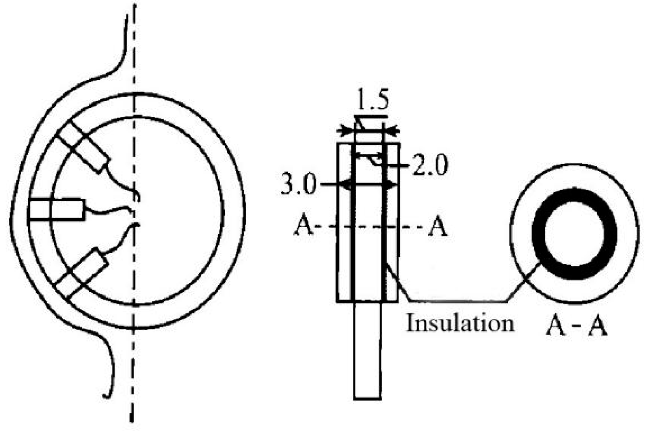
| Contact type | inserted conductivity probe method | The wall-contact probe calculates liquid film thickness from electrical conductivity differences between air and liquid, using signals generated by film thickness variations | Conductive liquids 0.05 mm ≤ δ ≤ 5 mm | ±5–10% | 5–10% | 0.1 μm | Simple structure, easy to operate | Affected by grounding currents, probe size, signal interference, and temperature changes, leading to lower accuracy | Refs. [14,15,16,17] |
| embedded conductivity probe method | The embedded probe calculates film thickness from electrical conductivity differences between the pipe wall and the liquid | Conductive liquids. 0.1 mm ≤ δ ≤ 2 mm | ±3–5% | <3% | 0.05 μm | Accurate measurement | Complex structure, high precision required, limited applicability | Ref. [18] | |
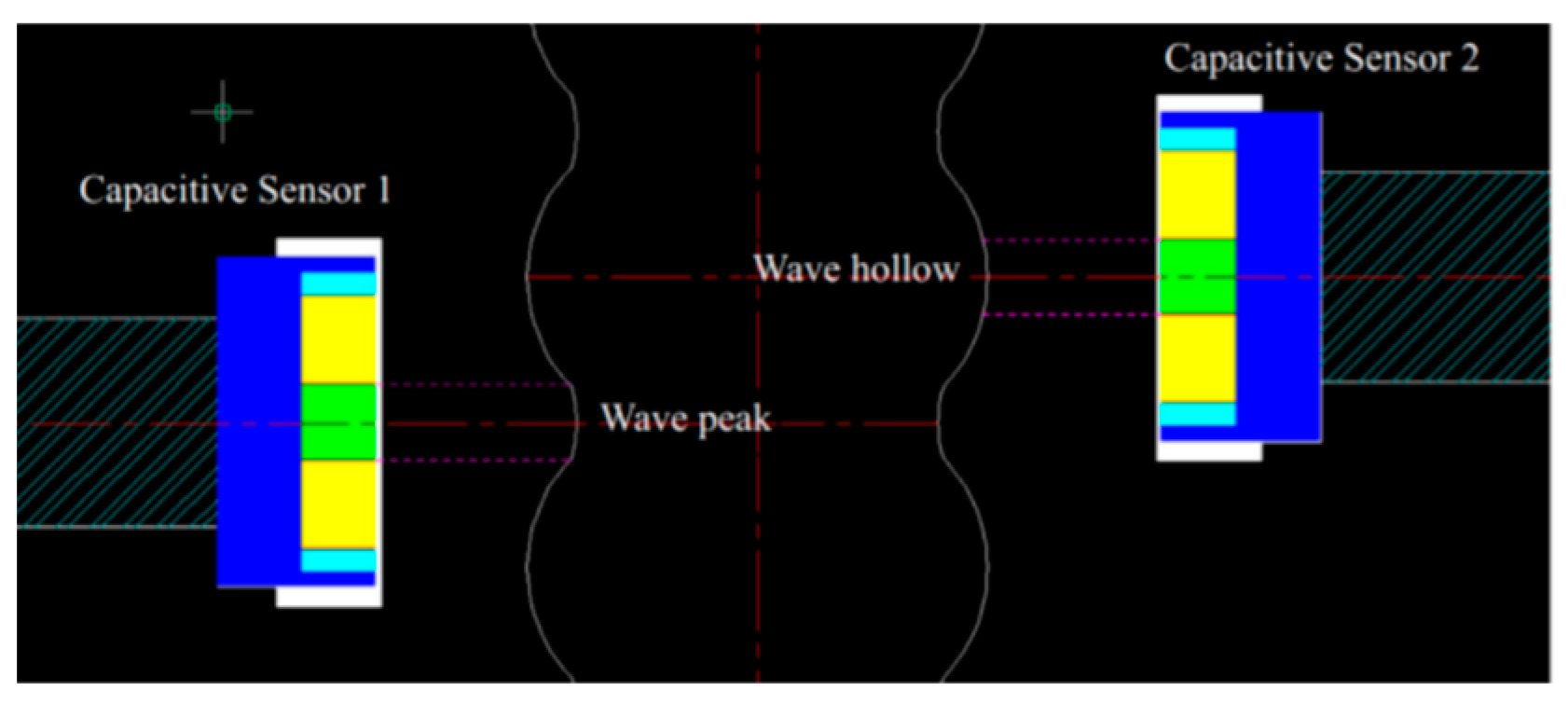
| Non-contact type | capacitance method | A metal plate parallel to the wall forms a capacitor, with capacitance varying with liquid film thickness, enabling thickness calculation | Conductive liquids. 0.0025 mm ≤ δ ≤ 2.5 mm | ±5–8% | 2–4% | 1 nm | Simple structure, easy to operate | Affected by film fluctuations and splashing, resulting in lower accuracy | Refs. [19,20] |
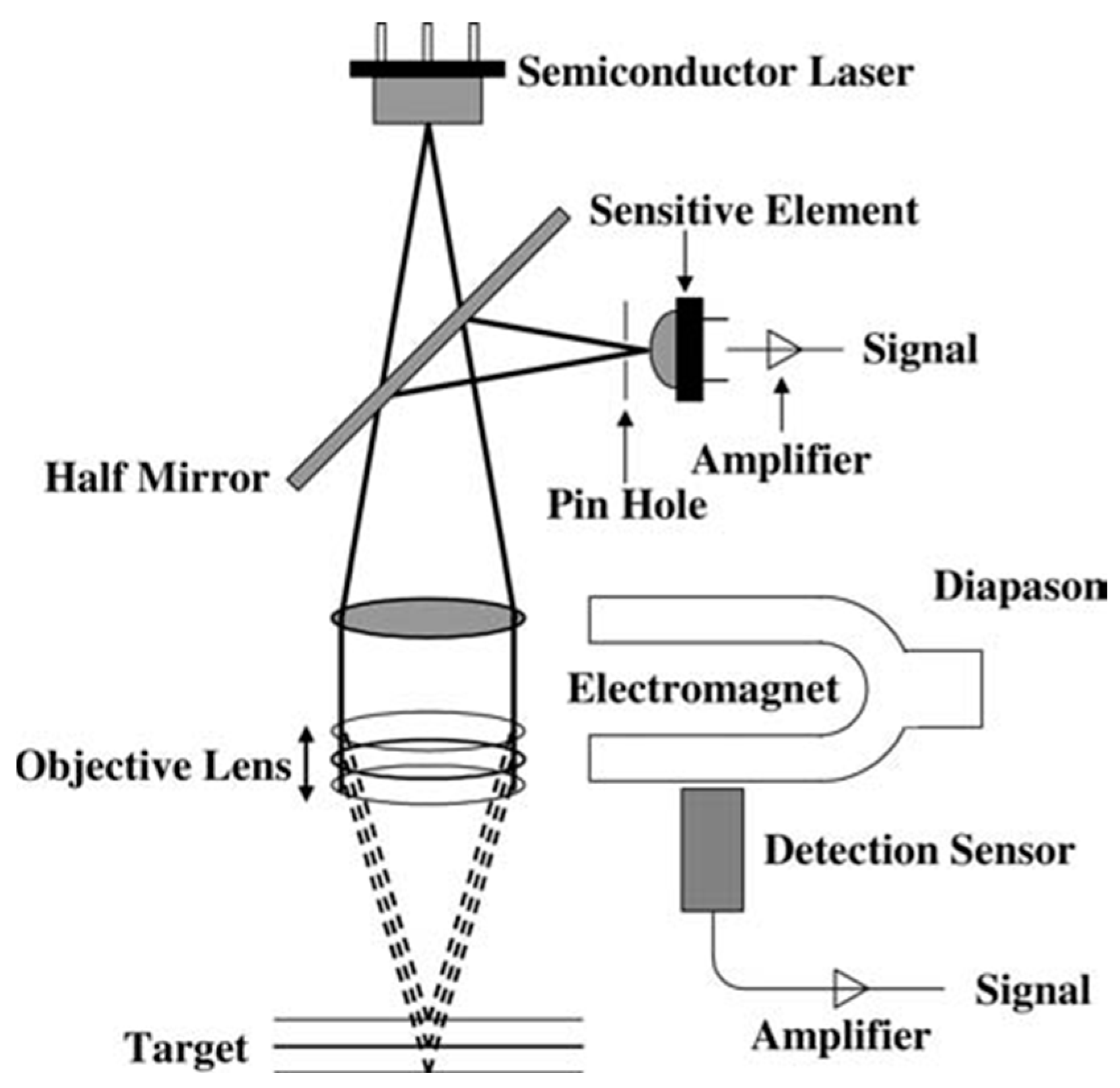
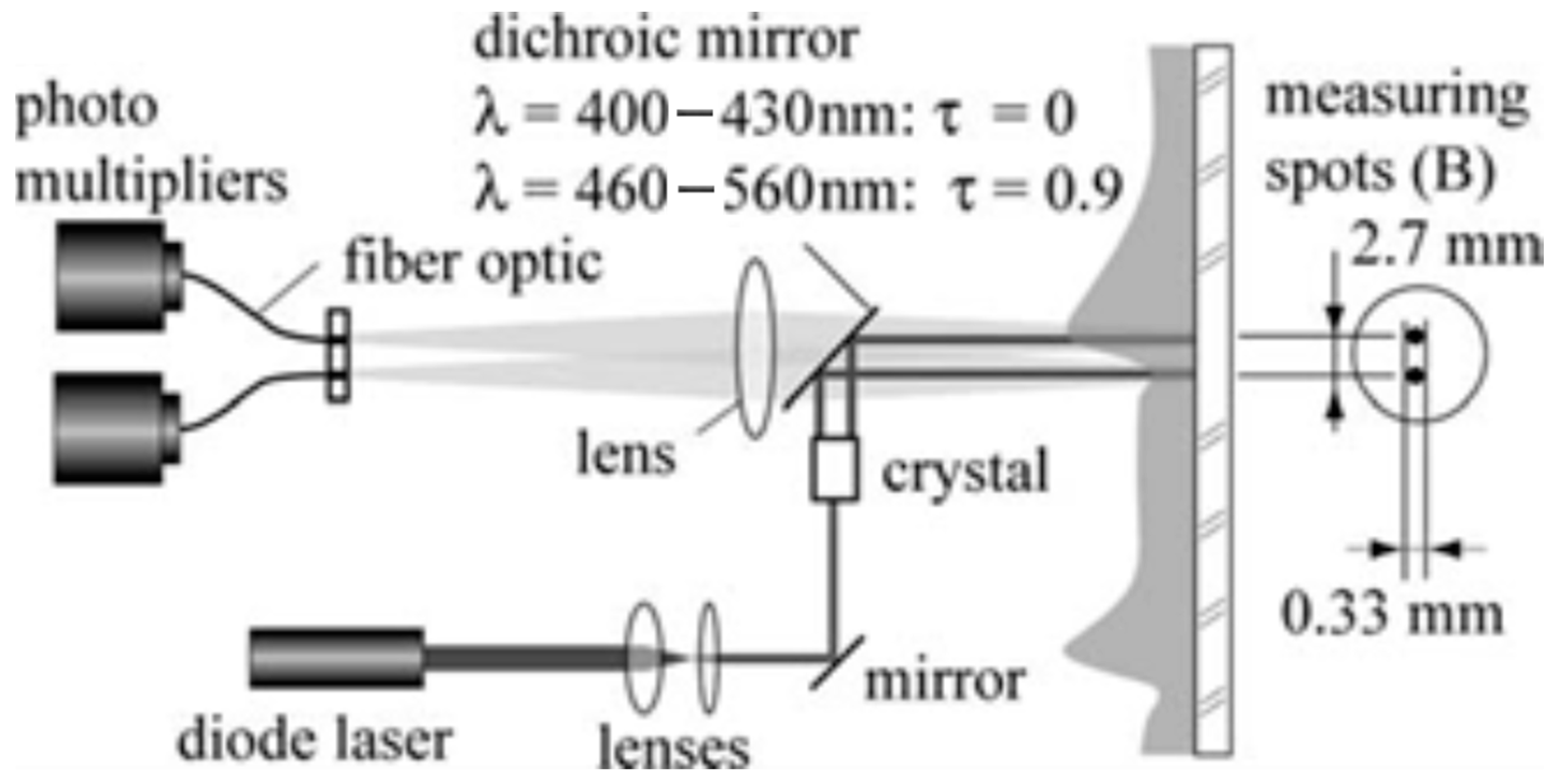
| spectral confocal displacement meter method | By exploiting lens dispersion and focusing, varying reflected spectra from the liquid film surface enable thickness measurement through the objective lens movement | Transparent liquids. 0.05 mm < δ < 5 mm | ±1–5 nm | <1% | 0.1 nm | High measurement accuracy and frequency, with a relative error of 1% | Film fluctuations weaken reflection signals, complicating the experiment, with a narrow range | Refs. [21,22,23,24] | |
| fluorescence intensity method | Liquid film thickness is determined by adding a fluorescent dye and measuring the fluorescence intensity | Transparent liquids. 0.01 mm < δ < 0.5 mm | ±5–10% | 3–5% | 1 nm | Simple method, high accuracy, capable of measuring liquid film velocity | Calibration is difficult, and fluorescent dye alters fluid properties | Ref. [22] | |
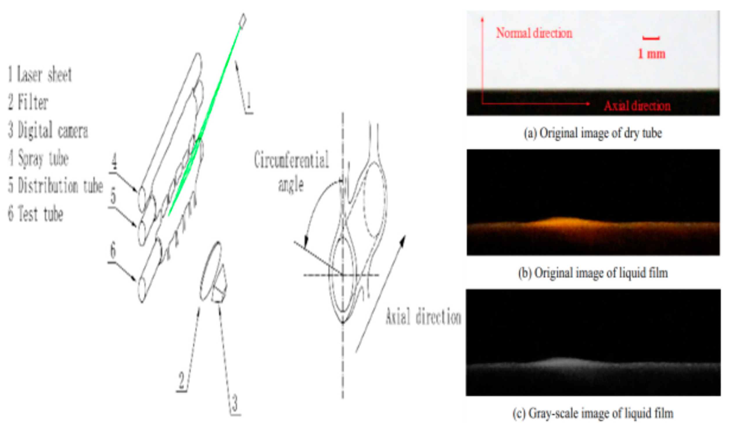
| laser-induced fluorescence combined with an image processing method | Liquid film thickness is measured by adding a fluorescent dye, laser-induced coloration, and analyzing grayscale images captured by a high-speed camera | Transparent liquids. 0.1 mm < δ < 10 mm | ±2–5% | 1–3% | 5 nm | Simple process | Unable to measure instant film fluctuations, difficult image processing, with a 5% relative error | Refs. [25,26,27] | |
| b1 | b2 | b3 | b4 | b5 | b6 | R2 | |
|---|---|---|---|---|---|---|---|
| droplet→ droplet-column | 0.0346 | −0.0131 | −0.0580 | 0.0469 | 0.0660 | 0.3100 | 0.9975 |
| droplet-column →column | 0.0866 | −0.0289 | 0.1199 | −0.0288 | 0.1346 | 0.2888 | 0.9951 |
| column→ column-sheet | 0.1803 | −0.0791 | 0.2349 | 0.0032 | 0.9649 | 0.2472 | 0.9982 |
| column-sheet →column | 0.1325 | −0.0737 | −0.2419 | 0.1535 | 1.0771 | 0.2648 | 0.9954 |
Disclaimer/Publisher’s Note: The statements, opinions and data contained in all publications are solely those of the individual author(s) and contributor(s) and not of MDPI and/or the editor(s). MDPI and/or the editor(s) disclaim responsibility for any injury to people or property resulting from any ideas, methods, instructions or products referred to in the content. |
© 2025 by the authors. Licensee MDPI, Basel, Switzerland. This article is an open access article distributed under the terms and conditions of the Creative Commons Attribution (CC BY) license (https://creativecommons.org/licenses/by/4.0/).
Share and Cite
Wang, Z.; Li, M. A Comprehensive Review on Studies of Flow Characteristics in Horizontal Tube Falling Film Heat Exchangers. Energies 2025, 18, 3587. https://doi.org/10.3390/en18133587
Wang Z, Li M. A Comprehensive Review on Studies of Flow Characteristics in Horizontal Tube Falling Film Heat Exchangers. Energies. 2025; 18(13):3587. https://doi.org/10.3390/en18133587
Chicago/Turabian StyleWang, Zhenchuan, and Meijun Li. 2025. "A Comprehensive Review on Studies of Flow Characteristics in Horizontal Tube Falling Film Heat Exchangers" Energies 18, no. 13: 3587. https://doi.org/10.3390/en18133587
APA StyleWang, Z., & Li, M. (2025). A Comprehensive Review on Studies of Flow Characteristics in Horizontal Tube Falling Film Heat Exchangers. Energies, 18(13), 3587. https://doi.org/10.3390/en18133587