Article

Experimental Testing of New Concrete-Based, Medium-Temperature Thermal Energy Storage Charged by Both a Thermal and Electrical Power Source

ENEA, Italian National Agency for New Technologies, Energy and Sustainable Economic Development, Lungotevere Thaon di Revel 76, 00186 Rome, Italy
*
Author to whom correspondence should be addressed.
Energies 2025, 18(13), 3511; https://doi.org/10.3390/en18133511
Submission received: 28 May 2025 / Revised: 24 June 2025 / Accepted: 30 June 2025 / Published: 3 July 2025
(This article belongs to the Special Issue Stationary Energy Storage Systems for Renewable Energies)

Abstract

This study aims to explore a new concept for a Power to Heat (P2H) device and demonstrate its effectiveness compared to a thermal heating method. The proposed concept is a medium-temperature system where electro-thermal conversion occurs via the Joule effect in a metallic tube (resistive element). This tube also serves as a heat exchange surface between the heat transfer fluid and the thermal storage medium. The heat storage material here proposed consists of base concrete formulated on purpose to ensure its operation at high temperatures, good performance and prolongated thermal stability. The addition of 10%wt phase change material (i.e., solar salts) stabilized in shape through a diatomite porous matrix allows the energy density stored in the medium itself to increase (hybrid sensible/latent system). Testing of the heat storage module has been conducted within a temperature range of 220–280 °C. An experimental comparison of charging times has demonstrated that electric heating exhibits faster dynamics compared to thermal heating. In both electrical and thermal heating methods, the concrete module has achieved 86% of its theoretical storage capacity, limited by thermal losses. In conclusion, this study successfully demonstrates the viability and efficiency of the proposed hybrid sensible/latent P2H system, highlighting the faster charging dynamics of direct electrical heating compared to conventional thermal methods, while achieving a comparable storage capacity despite thermal losses.

1. Introduction

The increasing use of renewable energy sources necessitates flexible, affordable, and efficient electrical storage to bridge the gap between energy supply and demand. Carnot battery technology can contribute to addressing this mismatch by buffering electrical energy provided by renewable sources (PV, wind) [1]: it converts electricity into heat and stores it using a resistive heater or heat pump when electricity generation exceeds demand (charging cycle). Conversely, during periods of high electricity demand, it generates power from this stored thermal energy (in its discharging step). Carnot batteries (CBs) are well-suited for medium-to-long duration energy storage (hours to days), making them complementary to short-duration electrochemical batteries. Furthermore, the components are well-established industrial equipment. Finally, the thermal energy storage materials (like molten salt or rocks) are generally inexpensive, making the overall cost of large-scale storage potentially lower than more conventional technologies. Therefore, this technology can promote the increasingly widespread exploitation of renewable electrical sources and facilitate inter-sectoral integration and energy flexibility [1] by means of robust and conventional processes and equipment.
Charging Carnot batteries can be carried out with different possible heating technologies, such as pumped thermal electricity storage (PTES) [2] systems based on the use of electric heaters, while discharging can be accomplished with various thermal engine technologies, such as Rankine or Brayton thermal engines [3]. Since Carnot batteries are based on heat pumps and thermal engines, they consist of pumps, compressors, expanders, turbines, and heat exchangers, all of which are components that can be easily scaled. For this reason, Carnot batteries could be an alternative for pumped hydro energy storage (PHES) and compressed air energy storage (CAES). Compared to these, Carnot batteries may have lower efficiencies but with the advantage of being installable anywhere, not relying on pre-existing reservoirs or caves. Among network-scale electrical energy storage (EES) technologies, Carnot batteries have the lowest average technology readiness level (TRL), although they are becoming increasingly popular. For this reason, the actual potential of this heterogeneous technological group is not yet clear, despite ongoing research. Recently, a significant number of publications have been dedicated to CB [1,4,5,6,7,8,9,10,11,12,13,14,15,16]. Typically, a Carnot battery delivers power ranging from 10 to 1000 MW and has storage capacities of up to 100 GWh [7]. The smaller ones are based on organic Rankine cycle (ORC) and Stirling engines, while the larger ones are generally based on current thermal power plant technologies. The storage duration presently ranges between approximately 4 and 24 h but, with the increasing maturity of these systems and the increasing required storage duration, it may be possible to add further capacity at a relatively low cost. Systems using the heat pump principle for charging are much more addressed by the scientific literature due to their high efficiency.
The reported round-trip efficiencies in the literature span a broad spectrum, from 25% to 80% [3]. Notably, co-fueled systems can surpass this range, reaching even greater efficiencies. High round-trip efficiency is often reported for conceptual systems, typically offering optimistic theoretical results. Therefore, caution is necessary, especially for systems still in conceptual or initial design stages, given the absence of experimental data. Even when demonstration and pilot plants exist, their reported efficiencies are usually theoretical projections for full-scale plants and often remain unverified.
CB systems are seeing rapid development, especially in recent years, with the first large-scale network pilot launched in 2019, and full commercialization of 13 kW modular units in 2021. Further pilot and commercial systems are scheduled for commissioning in 2022 and 2023. Once experience is gained on these systems and renewable energy capacity further increases, even faster development can be expected [16].
Furthermore, there is a significant development of thermal energy storage systems where CB application is specifically suggested as one of the use cases. An interesting trend in these systems, when equipped with high-temperature storage, is a re-adoption of technologies previously considered for concentrated solar power plants and industrial process heat. This confirms that CB are not so much a new technology, but rather a novel combination and application of existing ones. As such, perhaps due to simplicity, electrically heated systems are mostly absent from the scientific literature, although they have the prospect of a low-cost, simple, and robust system. It is worth noticing that the International Energy Agency (IEA) has recently completed, in this sector, the work of Task 36, dedicated to Carnot batteries, within the Technology Collaboration Programme “Energy Storage” (Energy Storage Technology Collaboration Programme—IEA ES TCP (iea-es.org)), and has just launched Task 44 “Hi CBest: Power-to-Heat and Heat integrated Carnot Batteries for Zero-Carbon (industrial) Heat & Power supply”. Finally, it is expected that reducing the cost of the hybrid TES system compared to a traditional one will actively promote this technology and gain investor confidence.
This study specifically focuses on the analysis of electro-thermal conversion (P2H—Power-to-Heat) systems integrated with thermal energy storage (TES), known as thermal electrical energy storage (TEES). The development of these systems requires engineering materials and components for thermal energy storage that can accommodate combined thermal and electrical input. Practically, this means conceptualizing and developing integrated systems for dissipative electricity-to-heat conversion and thermal storage. These systems, while based on existing sensible/latent heat thermal storage technology, demand material reformulation, revised component design, along with experimental characterization and validation. The basic concept of this study is a TEES system operating at a medium temperature (150–350 °C) in which the dissipative electro-thermal conversion (Joule effect) takes place within the metallic tube, which serves as the heat exchange surface between the heat transfer fluid (HTF) and the heat storage medium (HSM) of the TES.
The TES system, here discussed, mainly uses the sensible heat of cementitious materials enhanced by the addition of shape-stabilized phase change materials (PCMs) for latent heat storage [17,18,19,20,21,22,23,24,25,26,27,28,29,30,31,32,33,34]. Regarding sensible heat thermal energy storage (SHTES) based on concrete materials, it has a limited thermal storage capacity (Table 1) but offers the great advantage of using widely available, low-cost storage media. However, its application in systems operating up to approximately 400 °C requires a thorough study and evaluation of its mix-design and manufacturing/treatment processes. Furthermore, due to concrete’s inherently low thermal diffusivity, these materials must be modified to promote thermal conductivity, along with appropriately sizing the heat exchange system [35].
Past studies on these systems, notably by the German Aerospace Center (DLR) [37,38,39,40] and University of Arkansas [41], have consistently highlighted some issues: (i) cementitious materials often exhibit severe cracking and low durability; (ii) ceramic matrix concretes, when used, led to increased costs; and (iii) artifacts, often cast in place, are always significantly large (some tens of m3) and have a strong visual impact. Despite these limitations, commercial initiatives have been launched within the sector. Notably, ENERGYNESTTM offers commercial solutions using a material called Heatcrete [27]. These solutions provide modular TES sizes up to 4 MWh, declared scalable up to 1000 MWh (IRES 2022 congress, oral presentation by Magnus Mörtberg: “Thermal Storage and Industrial Heat”).
The latent heat thermal energy storage (LHTES) system offers two key advantages for a range of industrial applications:
  • Compactness (high density of accumulated energy, even 3–5 times that of SHTES), thanks to the exploitation of latent heat.
  • Temperature stability of the supplied heat (melting temperature of the PCM) [42].
LHTES systems have already found widespread application at low temperatures but are still in a research and development phase for medium- and high-temperature applications. Above 120 °C, the usable PCMs are generally salts, characterized by low thermal conductivity/diffusivity and a series of characteristics (stability, corrosion) to be appropriately considered. Particular effort has been dedicated in the literature to understanding the physical phenomena related to the phase change, investigating geometries designed to facilitate it, and analyzing systems aimed at promoting heat exchange (e.g., fins) between the piping and the storage medium [43,44,45,46]. Among possible methods of promoting conductivity, the development of materials with inherently enhanced properties has also been studied. These materials consist of a base salt to which a small quantity of nanoparticles (Nano Enhanced PCM—NEPCM) is added to improve thermal characteristics, such as conductivity [47,48].
The cementitious material considered in the present study resulted from an iterative optimization work conducted by ENEA, based on compositional modifications. Using standard constituents, this concrete was designed for high-temperature (up to 400 °C) operation, offering durability and excellent heat exchange properties. In the latest formulations, small quantities (5–10% by weight) of micro-encapsulated PCM (mEPCM) were added to increase the concrete’s stored energy density (7–10% [49]), thereby making the TES more compact [27]. It is important to note that the advantage of using microencapsulated PCM is that it effectively prevents any material leakage. Miliozzi et al. observed a 7% energy density increase in their experiments by adding 5%wt of mEPCM (stabilized solar salts) in the cement matrix. Since the material in this application functions solely for thermal storage and not as a structural component, variations in its mechanical properties have theoretically no significant influence, at least up to 10%. Anyway, with the aim of verifying the compression and indirect tensile strength, mechanical tests were conducted on material samples after heating (up to 400 °C) [30]. At 300 °C, the compression strength of concrete without PCM was 25.39 N/mm2 compared to 20.08 N/mm2 with 10%wt PCM, while the indirect tensile strength was 6.03 N/mm2 and 2.35 N/mm2, respectively [30].
When considering charging/discharging dynamics, the integration of mEPCM influences heat transport within the material, particularly during mEPCM’s melting/solidification transients. This is because the PCM’s thermal diffusivity is inherently lower than that of concrete, a difference that becomes more pronounced during the phase transition as the PCM’s apparent heat capacity rises due to latent heat absorption/release. As a result, heat transfer within the mEPCM inclusions is slower, extending the charging/discharging phases compared to a standalone cement module. However, since mEPCM constitutes only 10% by weight of the cement matrix, the charging/discharging duration of the overall storage module does not substantially change.
A small-sized thermal storage element (3.00 × 0.22 × 0.22 m) using this newly developed material was studied, designed, and optimized. This element can be considered the base unit for thermal storage modules of flexible dimensions and capacity. These elements were characterized using “ad hoc” equipment, capable of testing the TES modules under operating cycles, like those expected in a hypothetical industrial plant. The results were in line with preliminary numerical simulations [50]. Research efforts were focused on identifying materials that are low costs, non-toxic, and widely available, and developing solutions that are flexible in terms of size (capacity) and integrability. The ultimate goal is to develop solutions that can be used in the national energy and production system, where the need for flexible and compact systems, including medium–small capacity, is relevant, both for industrial heat supply and for small-scale (distributed) power systems.
The objective of this work is to propose this thermal storage module as a TEES system capable of being powered by both electricity and heat, in the perspective of a cost-effective CB approach. The HSM used is a concrete mixture with the addition of 10%wt of mEPCM. A preliminary experimental analysis of the thermal behavior of this thermal storage module is here presented, in order to verify the technical feasibility of the proposed material for this specific application.
The article is structured to first detail the materials and methods employed, then present the experimental tests and finally comment on the obtained results.

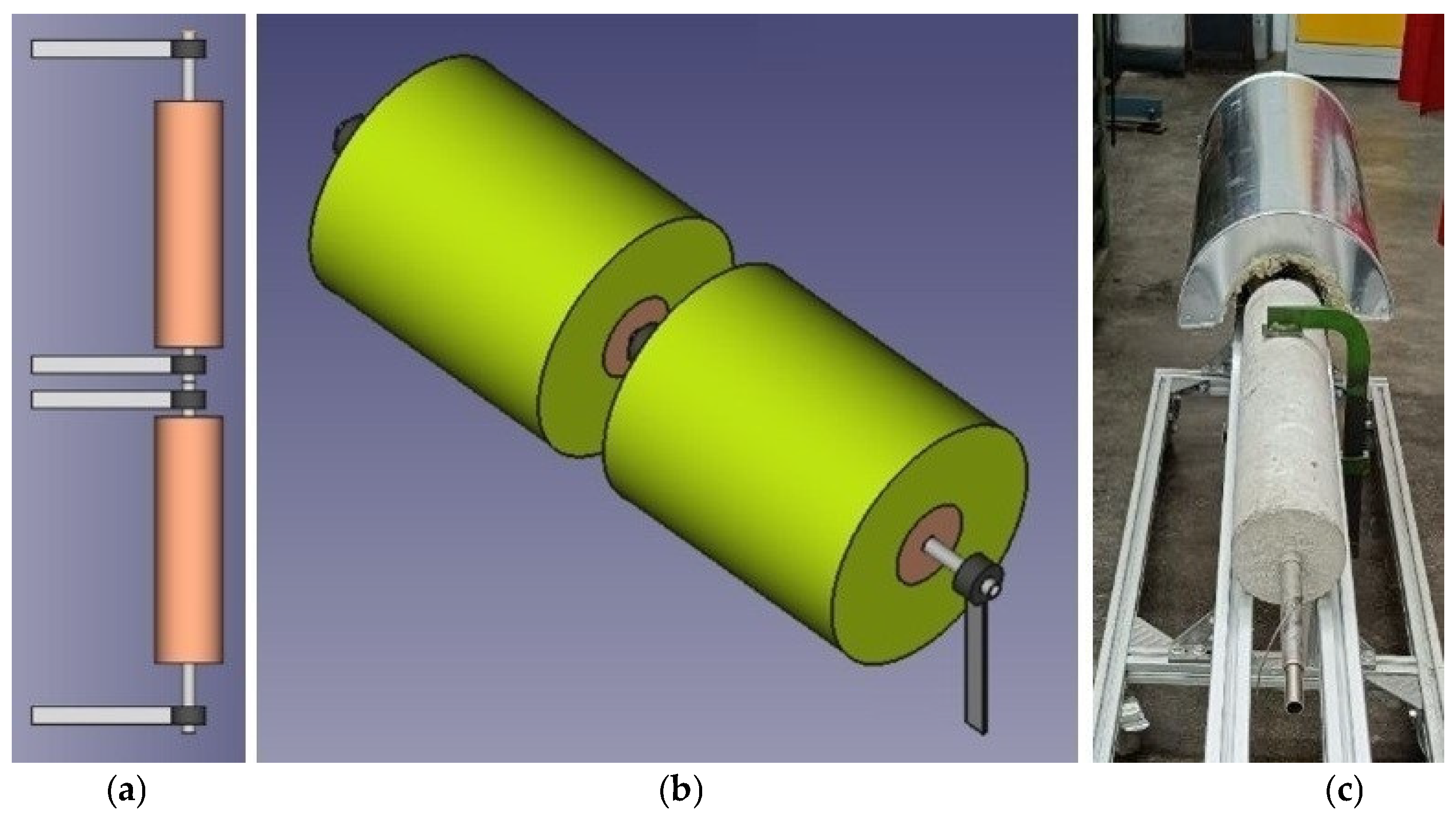
2. Materials and Methods

The experimental section of the TEES here proposed is composed of two concrete thermal storage devices connected in series. These devices are designed to operate within a temperature range of 200 °C to 280 °C, with a maximum design reference temperature of 350 °C. Each device consists of a metallic tube axially immersed in a cylindrical concrete shell (storage medium) in a “shell and tube” configuration. The metallic tube, which acts as the heat exchange surface, is made of AISI 304 stainless steel with a length of 1 m, an outer diameter of 21.3 mm, and a thickness of 1.65 mm. The cylindrical shell has a length of 0.7 m and an outer diameter of 120 mm.
The heat storage medium is a specially formulated base concrete designed for high-temperature operation and good and stable thermal performance. To this, 10% by weight of a PCM [51,52], specifically solar salts (a 60/40%wt mixture of sodium and potassium nitrates) stabilized in a porous matrix (mEPCM) [53,54,55,56,57,58], has been added. The PCM is encapsulated in diatomite [59,60], a highly porous fossil flour, at a weight ratio of 80–20%.
The test section was realized by connecting the two devices in series, leaving the heat exchange tube uncovered at its ends and in the central part. This configuration allows, during the electrical charging phase, the connection of the positive pole of a DC current generator to the uncovered central area and the connection of the negative pole to both the ends of the metallic tube. This way, the initial and final parts of the tube are at the same potential.
More specifically, the electro-thermal conversion is accomplished through the Joule effect [61] generated by a current passing through the metallic tube. The metallic tube simultaneously serves as the conduit for oil flow and the medium for electricity, which enables the Joule effect for heating. This effectively makes the tube an electric heater (rod). This is added to the text. The current I flowing through the tube generates heat in the tube itself with a power P that can be calculated using the well-known relation:
P = R · I 2 = V · I
where R represents the electrical resistance of the metal tube, V the voltage and I the electric current intensity. The resistance is given by the relationship:
R = ρ e l · L A t u b e
with ρ e l being the electrical resistivity at operative temperature, L being the distance between the poles, and Atube being the area of the cross-section of the exchange tube (in this case, the metallic section of the tube). Furthermore, the tube has four metal clamps capable of handling the calculated maximum amperage of 630 A per connection with the power supply. These clamps are located at the ends and in the central part (Figure 1a). This solution ensures that only the exchanger is energized, isolating it from the rest of the system.
The TEES element (Figure 1b) has been thermally insulated to have a surface temperature compliant with regulations and to prevent excessive heat loss. Rock wool with a thickness of 100 mm was used. All the insulation is protected by an aluminum sheet (Figure 1c).
Driven by environmental concerns and the ongoing phase-out of some commercial cements (i.e., Portland cement), new concrete formulations were studied by ENEA. Furthermore, in adherence to circular economy principles, a series of materials (fibers and aggregates) derived from industrial waste (steel slag, carbon fibers extracted from filters, etc.) were identified and incorporated as fibers and aggregates. After a comprehensive assessment of various potential materials, the composition ultimately selected for the thermal storage module is reported in Table 2.
This formula, which is derived from previous studies on fires in tunnels and nuclear accidents [62], allows energy to be stored both as sensible and latent heat, with a high thermal capacity and increased stored energy density compared to conventional concrete mixtures. In addition this material can operate effectively at medium–high temperatures (150–400 °C), by combining concrete materials with metal and polymer fibers, while retaining structural properties suitable for HSM.
The developed storage module was installed on the ENEA ATES (Advanced Thermal Energy Storage System) test plant to carry out its thermal characterization (Figure 2). The ATES infrastructure consists of an oil circuit, provided with a heating/cooling system (Julabo—HT30-M1 C.U., JULABO GmbH, Seelbach, Germany), capable of operating at temperatures up to 350 °C. This system is meant to be directly connected to the storage module under testing. The maximum heating power is about 3 kW, whereas the cooling power is 15 kW; the oil flow does not exceed 18 L/min. Through 4 electrically actuated valves, the experimental facility can generate a clockwise, anticlockwise or by-pass oil circulation; the latter allows rapid heating or cooling of the thermal fluid to enable the charging/discharging of the storage modules. The facility is also equipped with a control and data acquisition system, developed in the LabView® environment, which allows remote control and real-time monitoring of operating parameters (Figure 3).
In particular, the system is equipped with 16 thermocouples and 2 resistance temperature detectors (RTDs) to detect the following operating temperatures:
  • Temperature inside the tank(s) volume;
  • Temperature of the outer surface of the tube;
  • Temperature of the internal and external walls of the tank itself;
  • Temperature at the inlet and outlet of the tank and the inlet and outlet of the heater/cooler.
The experimental tests for the thermal characterization of the TEES system were designed and programmed to perform a series of thermal charging/discharging cycles of the storage modules. In these cycles, the thermal charging phase was powered electrically and/or thermally, while the thermal discharging phase was accomplished through cooling by HTF. Before starting the planned tests, it was necessary to degas the storage modules (to eliminate free water present in the concrete) by circulating diathermic oil at a flow rate of 18 L/min and a temperature of 140 °C for 24 h. Subsequently, two charging/discharging tests of the storage modules were performed: one with electrical charging and the other one with thermal charging through the heat transfer fluid. In both tests, the discharging phase was always accomplished through the heat transfer fluid (Table 3).
Afterward, a partial load test was performed. In this test, a charging/discharging cycle with electric heating (P2H) was repeated, where the charging and discharging time was reduced to 5 and 2.5 h, respectively. Finally, a cyclic functional test of the system was performed, completing a total of 4 cycles (Table 4).
As previously mentioned, these preliminary tests are aimed at verifying the feasibility of a system combining several innovative aspects. An analysis was conducted on the measurement uncertainty of the instrumentation installed on the ATES experimental plant. Specifically, during electric heating, temperature measurements collected by Class 1 K thermocouples have a tolerance of ±1.5 °C at 250 °C. This results in a standard uncertainty of 0.35%, including the rest of the measurement chain. Conversely, during heating or cooling by the HTF, errors arise not only from temperature measurement (using RTD/Pt100 Class A thermo-resistors with a tolerance of ±0.65 °C at 250 °C and a standard uncertainty of 0.11%) but also from flow measurements (KEM HMP 09 flowmeter, with an error of 1.42% and a standard uncertainty of 1.67%). The supplied/extracted power, which is a combination of these two measurements, is characterized by a standard uncertainty of approximately 12% for a temperature difference of 10 °C.

3. Results and Discussion

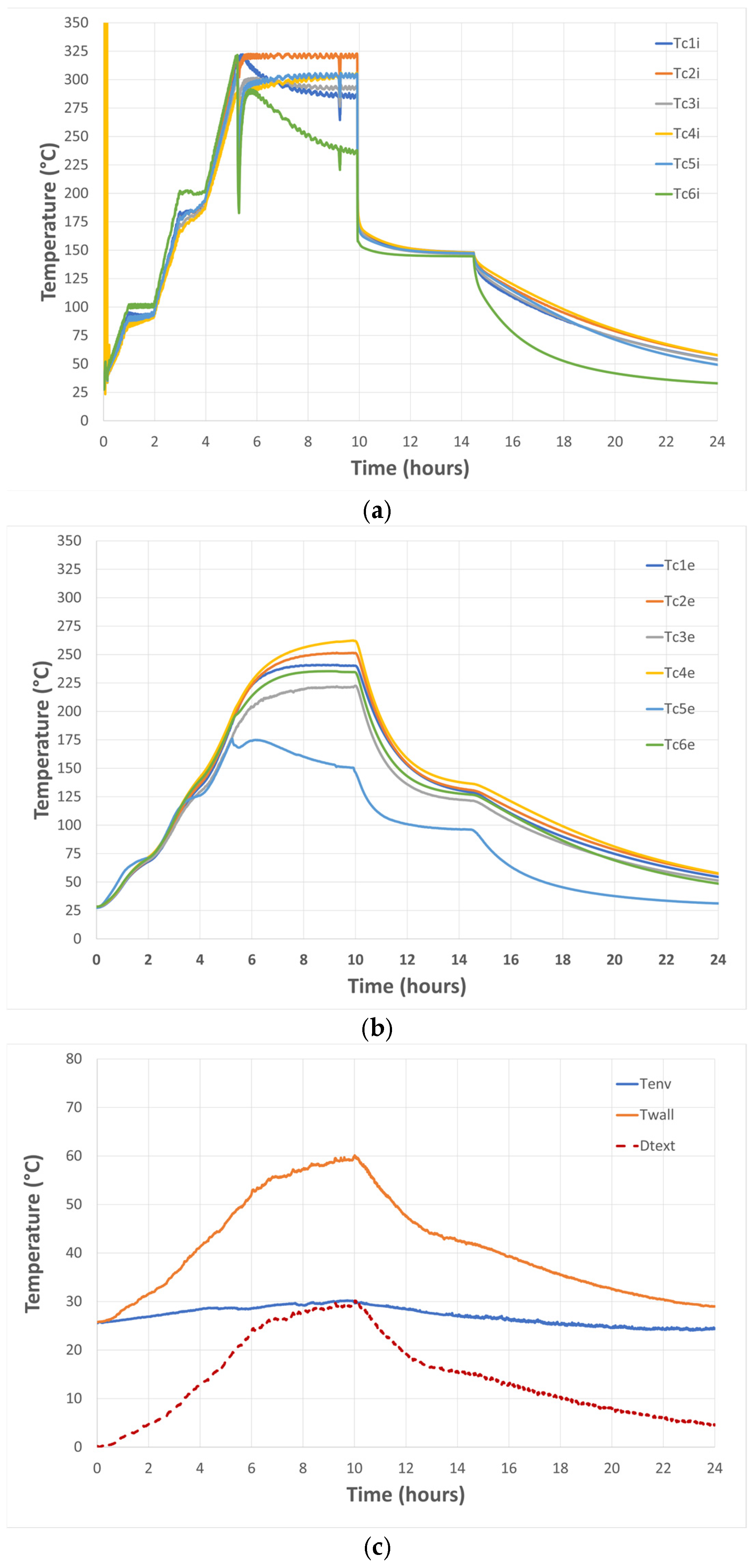
3.1. Charging/Discharging Test

As mentioned above, the charging/discharging cycles (Table 3) of the thermal storage system were repeated twice to verify the behavior of the storage module under thermal and electric heating (P2H conversion method).

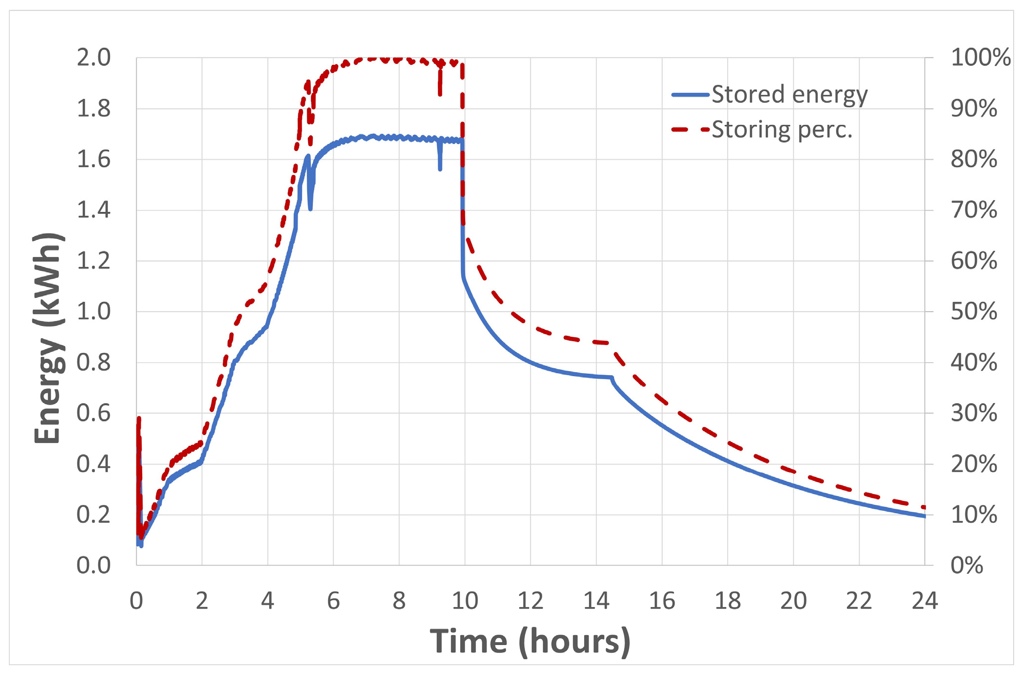
3.1.1. P2H Conversion Method

During the charging phase, the tube’s Joule heating continues until the target temperature is reached and maintained, and the HTF flow rate is kept at zero. The voltage remains between 2.5 and 3 V (maximum value), while the maximum current is 630 A. This results in a maximum delivered electrical power of 1.9 kWe. The electrical resistance of the tube was estimated to be 4.76 mΩ, a value consistent with theoretical calculations.
These units behave like two resistors powered in parallel. The electrical resistance of each unit was calculated using Equation (2) and considering only the metal tube’s properties (length: 0.9 m, section: 127 mm2, electrical resistivity: 1.3 Ohm.mm2/m at 300 °C): the resulting calculated electrical resistance is about 9.2 mΩ. Consequently, the equivalent electrical resistance of the system is 4.6 mΩ. Therfore, the difference between the measured and calculated electrical resistance is only about 3.5%. This minimal discrepancy suggests that no significant unaccounted electrical resistances are present.
Figure 4 shows the trends of the internal and external temperatures of the two devices, alongside the ambient temperature and the external mantle temperature of one of the devices. It is worth noting that Tc5e exhibited weird behavior, probably due to a partial detachment of the thermocouple during the test. The room temperature, maintained between 25 and 30 °C, confirms that the test was conducted at a sufficiently stable temperature despite its duration. However, the mantle temperature rises to approximately 60 °C, significantly exceeding the design specification of 35 °C, indicating that the insulation’s performance was below expectations.
During the charging phase, the internal temperature of the concrete module rapidly reaches the target temperature, evidencing the high efficiency of the Joule effect. An exception is observed in the temperatures of the outermost thermocouples (top and bottom), which are more susceptible to thermal losses. Conversely, during the discharging phase, the internal temperature rapidly decreases to around 170 °C, then declines more slowly towards 150 °C. The discharging time is estimated to be approximately two hours.
During the charging phase, external temperatures of the concrete module slowly increase due to the material’s diffusivity, asymptotically approaching temperatures between 220 and 250 °C. These values are lower than the target ones, due to heat losses toward the environment. In the discharging phase, the concrete module’s external temperature behavior is like its internal temperature, though characterized by a slower rate and lower temperature values resulting from the same factors previously mentioned. Figure 5 shows the estimated energy stored in the medium, relative to its energy content at 20 °C. As shown, approximately 1.69 kWh of thermal energy was stored after about 10 h, under near steady-state conditions. The charging time, reaching to the initial temperature plateau time (t = 5 h), was approximately 3 h, when reaching 98% of charging capacity. The discharging phase at 150 °C, occurring between 10 and 14.5 h, does not reach a true steady state, the duration of which should be around 5–6 h.
The module was initially fully insulated to limit thermal losses, but during testing, the metallic connection terminals to the power supply experienced excessive temperature increases. For safety reasons, it was necessary to de-insulate that part. For future tests, a higher thickness of the connection terminals will be applied. The thermal losses, estimated to exceed 300 W in the temperature range 120–140 °C and 1700 W in the range 280–290 °C, substantially condition the charging/discharging dynamics, alongside the material’s thermal diffusivity.

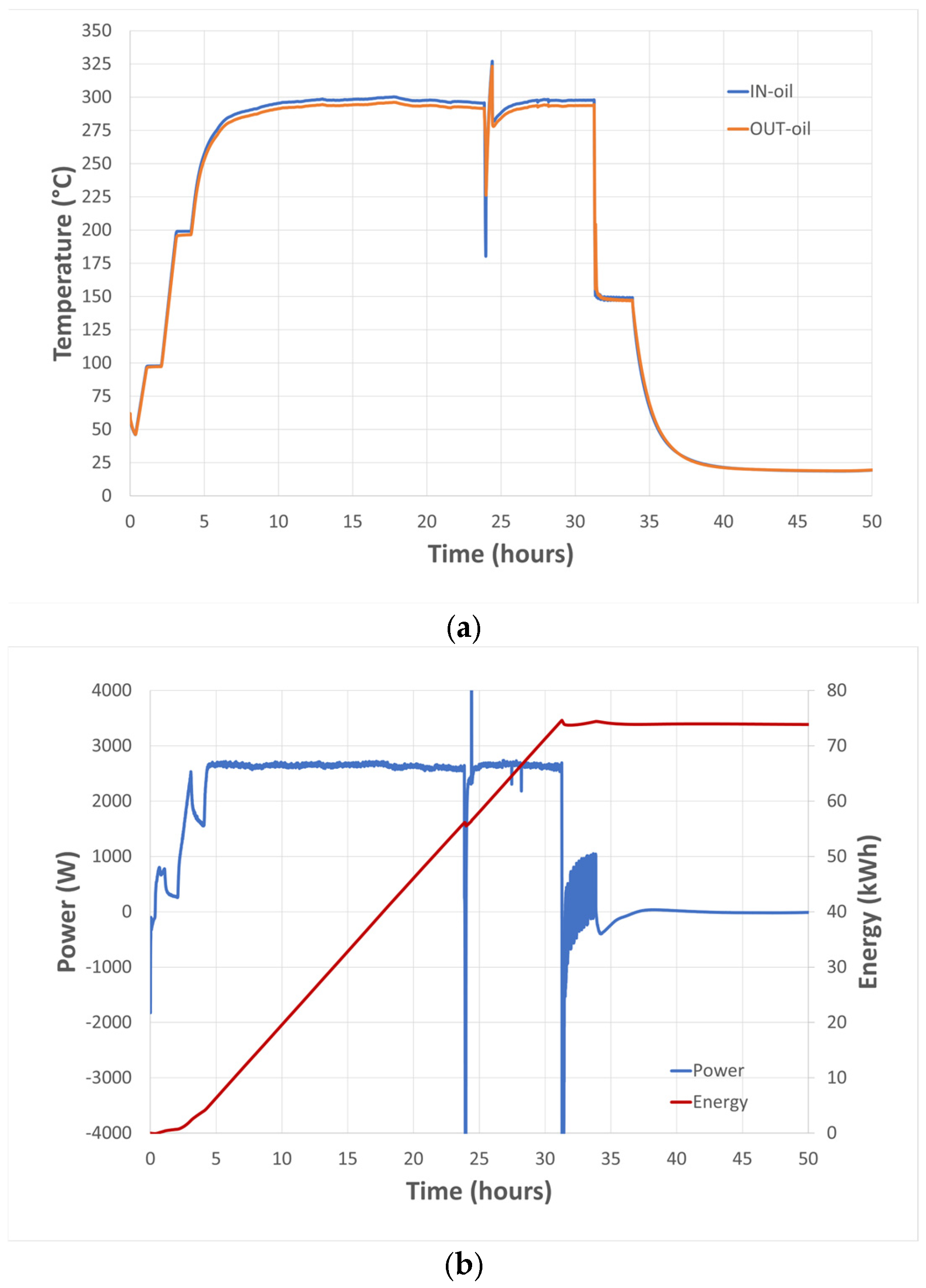
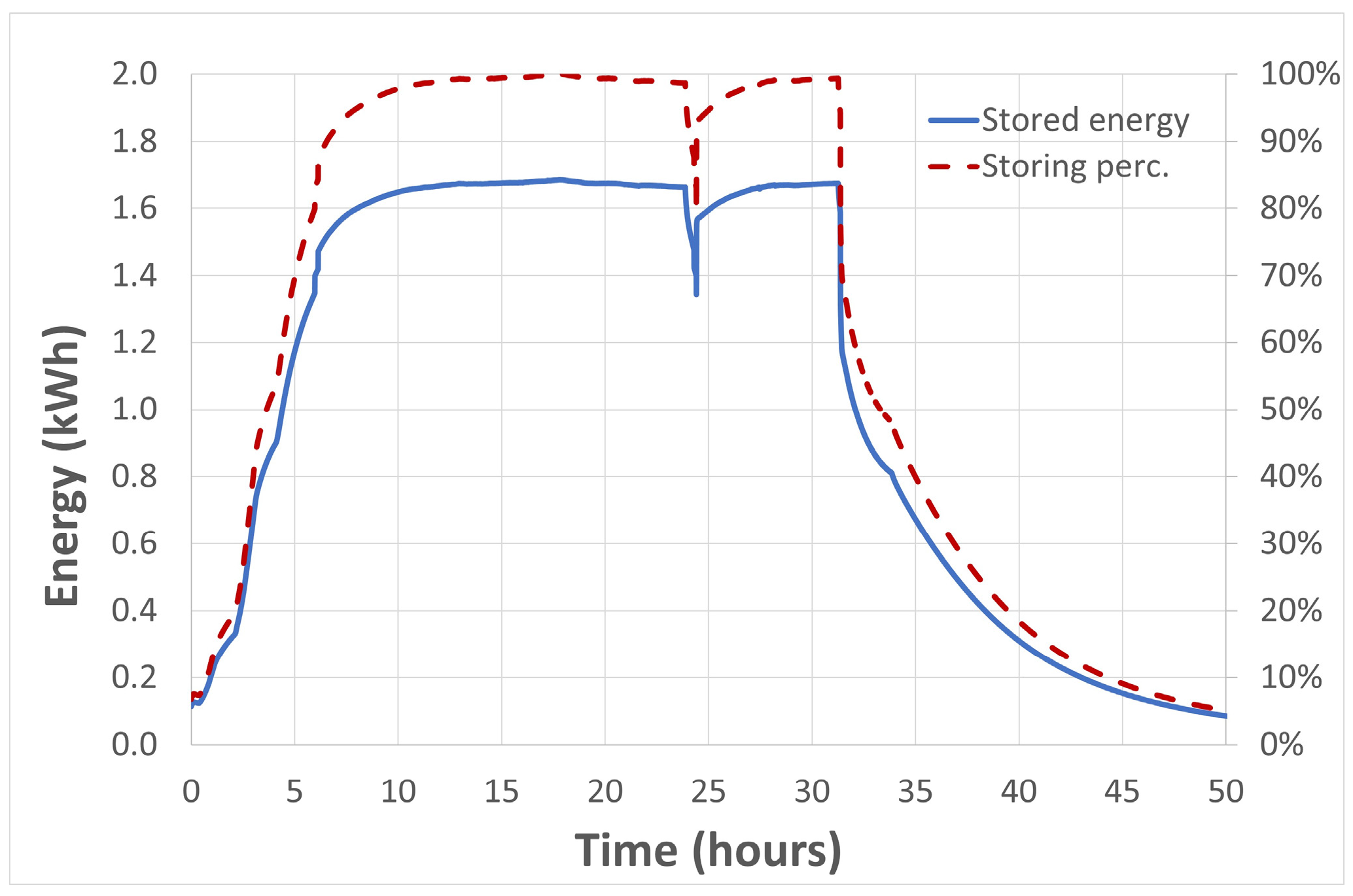
3.1.2. HTF Heating Method

The programmed charging/discharging cycles (Table 3) have identical target temperature values (320 °C and 150 °C), although the duration of the plateaus at a constant temperature differs slightly. Figure 6 shows the inlet and outlet temperatures from the heating/cooling system, as well as the power supplied/absorbed: during the charging phase, the heating thermal power is approximately 2.6 kW.
Figure 7 shows the trends of the internal and external temperatures of the two devices, the ambient temperature, and the external mantle temperature of one of the devices. The ambient temperature, maintained between 19 and 23 °C, demonstrates that the test was conducted at a sufficiently stable temperature despite its duration. In this case as well, the mantle temperature rises to approximately 53 °C, exceeding the design temperature (35 °C). This indicates that the insulation performs below expectations. During the charging phase, the internal temperatures stabilize after about 12 h at a temperature level lower than the target (280–290 °C). It indicates non-negligible heat losses from the HTF circuit, between the electric heater and the TEES. The discharging phase is very similar to that recorded in the previous test, although the duration is shorter.
Throughout the charging phase, the external temperatures of the concrete module increase slowly due to the material’s low diffusivity, asymptotically reaching temperatures between 220 and 250 °C. These values are lower than the target ones, due to heat losses. The concrete module’s external temperature behavior is similar to its internal temperatures, though characterized by a slower rate and lower temperature values resulting from the same factors previously mentioned.
Figure 8 shows the estimated energy stored in the medium, relative to its energy content at 20 °C. As can be seen, after approximately 15 h, under quasi-steady state conditions, about 1.68 kWh of thermal energy was stored, with a charging time of approximately 6 h, when reaching 98% of charging capacity, reading to the initial temperature plateau time (t = 9 h). The discharging phase at 150 °C, between hours 31 and 34, is still far from steady state condition, the duration of which is expected to be around 5–6 h. In this case as well, the dynamics of the charging/discharging processes are substantially influenced not only by the thermal diffusivity of the material but also by the high level of thermal losses, estimated to be more than 300 W at 120–140 °C and 1700 W at 280–290 °C.

3.1.3. Comparison of Methods

The following points can be highlighted from the comparison of the behavior of the two storage modules under electric and thermal charging:
  • Joule effect electric heating allows for the generation of heat at the target temperature directly within the heat exchange tube in a very effective manner. In the case of heating via heat transfer fluid, neglecting heat losses along the HTF circuit, heat transfer between the fluid and the heat exchange tube occurs through convection, which appears less effective than the former.
  • The heating method significantly impacts charging time: electric heating achieves charging in approximately 3 h from the start of the test, while in the second case the charging time is almost double (6 h). In fact, since the heat transfer within the storage medium is strictly connected to its thermal diffusivity, the possibility of having a high and stable internal temperature on the tube’s wall favors the charging speed.
  • In both cases, the concrete accumulated a maximum thermal energy of 1.68 kWh, which is 86% of its theoretical storage capacity (1.96 kWh). This limitation can be attributed to the high level of recorded thermal losses, ranging from 300 W at 150 °C up to approximately 1700 W at 290 °C.
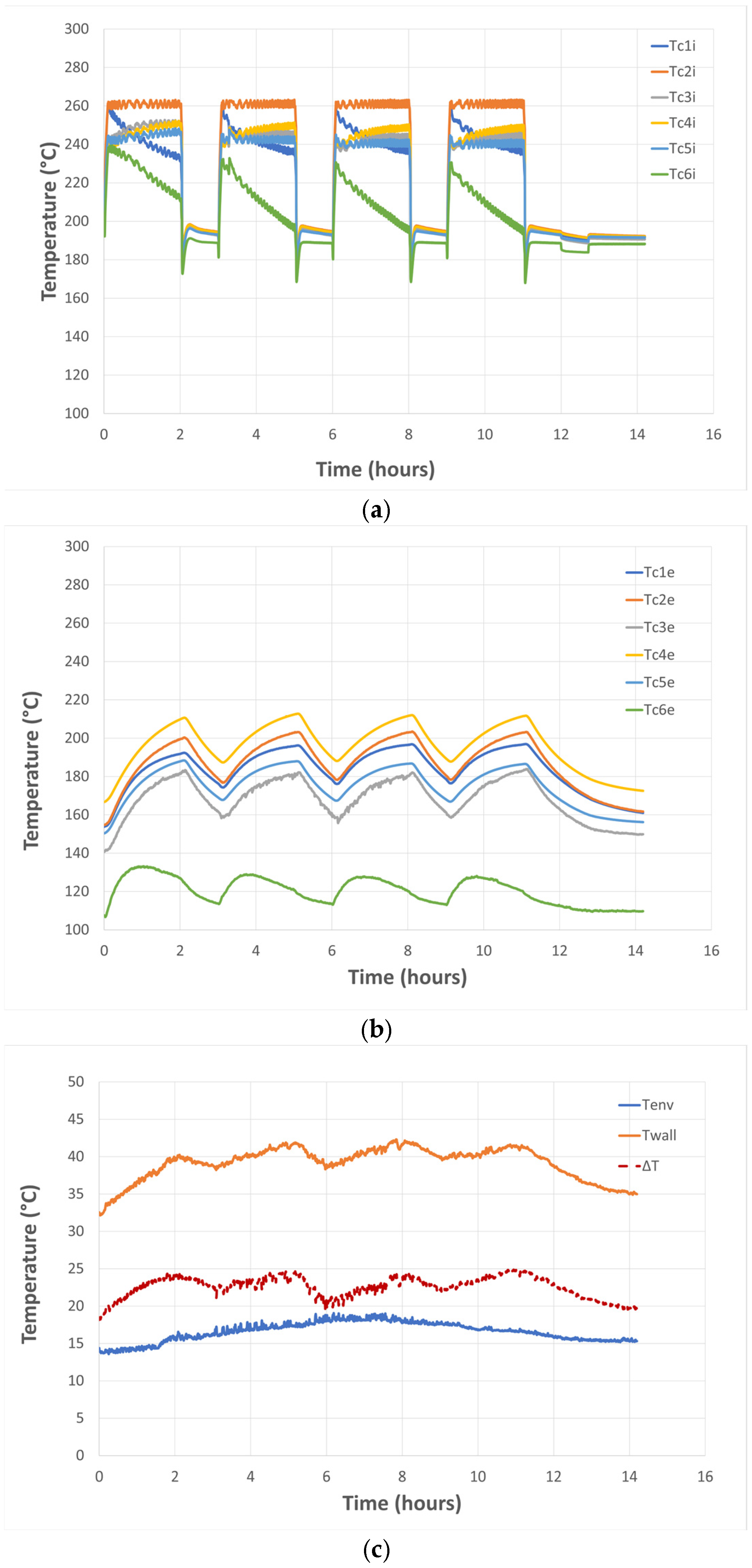
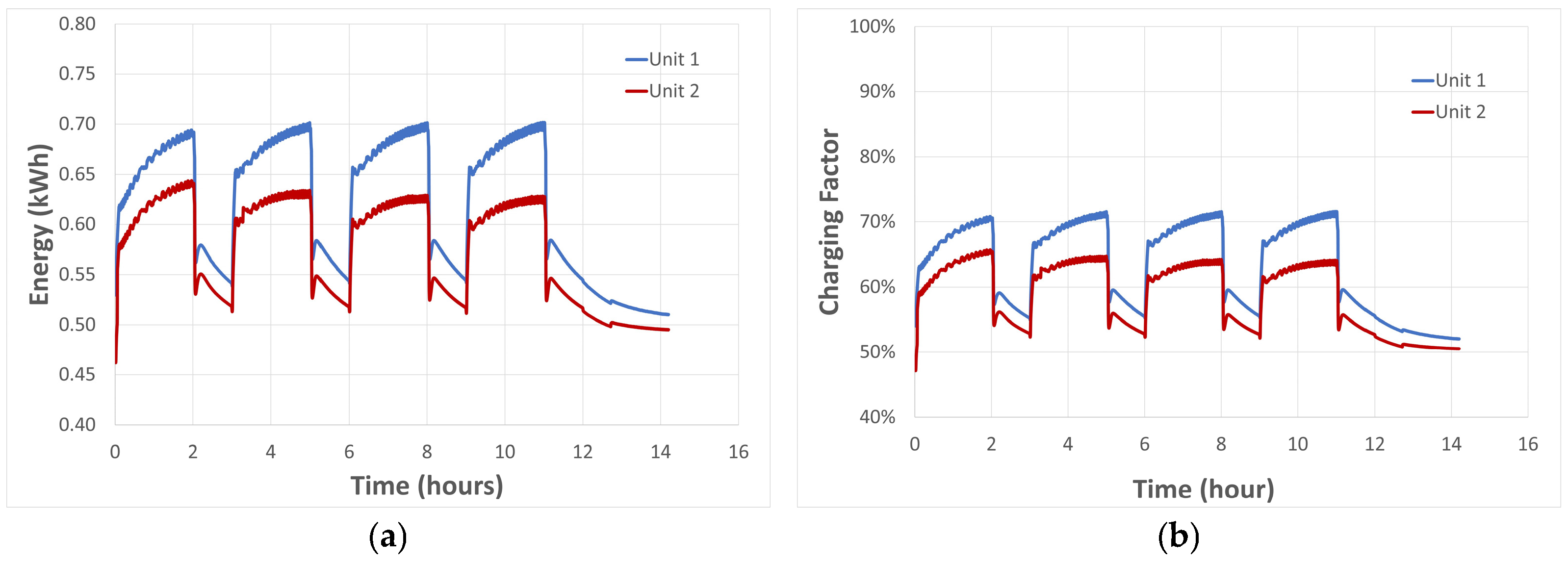
3.2. Cyclical Test

During the charging phase of each cycle, the tube is heated through the Joule effect to its target temperature, which is then maintained. The HTF flow rate is kept at zero. The system delivers a maximum electrical power of 1.7 kWe, with a maximum voltage of approximately 2.8 V and a maximum current of 630 A. Figure 9 shows the temperature trends of the two devices, specifically including their internal and external temperatures, in addition to the ambient temperature and the external mantle temperature of one of the devices. The ambient temperature, maintained between 15 and 20 °C, is sufficiently stable throughout the test. The mantle temperature rises above 40 °C (slightly higher than the design temperature of 35 °C). During the charging phase, the internal temperatures of the concrete module quickly reach the target, demonstrating the high effectiveness of the Joule effect. In contrast, the outermost thermocouples (top and bottom) exhibit temperatures affected by significant heat losses. In the discharging phase, internal temperatures within the concrete module rapidly drop to about 200 °C and then undergo a slower reduction to around 190 °C.
Regarding the concrete module’s external temperatures, during the charging phase, they slowly increase due to the material’s diffusivity, reaching 170–210 °C. These temperatures are lower than the target because of inherent thermal dispersions, which prevent the outer zones from utilizing the latent heat of the mEPCM. Conversely, during the discharging phase, the external temperature behavior of the concrete module is very similar to its internal temperatures, though characterized by a slower rate and lower values originating from the same factors previously mentioned.
Figure 10 shows the estimated energy stored in the storage medium, relative to its energy content at 20 °C. As can be seen, upon completion of the 2-h charging cycle, the maximum energy stored at 260 °C is approximately 1.31 kWh, with a filling factor of about 68%. However, the discharging phase, lasting 1 h, does not reach a steady state at 180 °C, indicating that the devises are not able to fully release their stored energy.
Therefore, the results demonstrate that, while the thermal behavior of the system stabilizes after the second cycle, the chosen durations for the charging and discharging phases are currently insufficient for an effective system operation. The installation of larger-sized modules could minimize thermal losses, while the use of finned tubes could rise the thermal exchange efficiency.

4. Conclusions

This work effectively demonstrates the promising performance of the proposed TEES (thermal energy electrical storage) concept. Key findings and future research directions are below reported.

4.1. Key Findings

  • Reliable and Efficient Electrical Charging: The TEES concept operates reliably and efficiently during its electrical charging phase. The measured electrical resistance of the exchange tube aligns with theoretical values, indicating minimal current leakage or additional electrical resistance.
  • Effective Internal Electro-Thermal Conversion: The internal electro-thermal conversion, based on the Joule effect, ensures stable heat generation within the tube at the target temperature. This heat is then effectively transferred to the concrete storage medium via conduction, differentiating it from heat transfer fluid convection.
  • Limiting Factors Identified: Despite the effective heat generation and transfer, the thermal diffusivity of the storage medium (concrete) remains a limiting factor in quickly and fully utilizing the storage capacity. Additionally, significant thermal losses were observed (300 W at 120–140 °C and 1700 W at 280–290 °C), which hinder system charging and reduce recovered thermal energy.
  • Crucial for Future Devices: Reducing these thermal losses is paramount for future laboratory-scale devices to allow for a more accurate assessment of the concept’s performance.
  • Cyclic Operation Stability: In cyclic operation, the system’s thermal behavior stabilizes after the second cycle. The duration of both charging and discharging phases is crucial for effective utilization of the storage medium’s capacity.

4.2. Future Research Directions

  • Larger Modules and Optimization: Future efforts will focus on developing and testing larger-sized modules to optimize their thermal performance by minimizing thermal losses. This will simultaneously accelerate the progress of the technology readiness level (TRL) of this compact and reliable TEES system concept, and will also allow its costs and performance to be evaluated.
  • Multi-Arrayed Configurations: As a next step, a series of modules will be created and integrated into multi-arrayed configurations (combining series and parallel layouts). This will facilitate the testing of operational strategies to optimize the simultaneous charging of these modules with both electricity and heat. The use of larger modules is desirable to minimize thermal losses and increase the TRL of this innovative TEES system concept.
In conclusion, the successful demonstration of the TEES concept’s reliable electrical charging and effective internal electro-thermal conversion lays a strong foundation for its future development, with ongoing research focused on optimizing module size, minimizing thermal losses, and exploring multi-arrayed configurations to advance its Technology Readiness Level and assess its overall performance.

Author Contributions

Conceptualization, R.L. and A.M.; methodology, M.L. and D.N.; validation, M.L.; formal analysis, A.M.; investigation, R.L.; data curation, M.L.; writing—original draft preparation, R.L., D.N., A.M. and M.L.; writing—review and editing, R.L., D.N., A.M. and M.L.; funding acquisition, R.L. All authors have read and agreed to the published version of the manuscript.

Funding

This research was funded by the Italian Ministry of Environment and Energy Security through the Research on Electric System—PTR 2025-27—Objective: Technologies—Project 1.2: Electrochemical and thermal storage technologies-WP4: Thermal Storage: materials and innovative systems.

Data Availability Statement

The original contributions presented in this study are included in the article. Further inquiries can be directed to the corresponding author.

Conflicts of Interest

The authors declare no conflicts of interest.

Abbreviations

The following abbreviations are used in this manuscript:
CAESCompressed-Air Energy Storage
CBCarnot Battery
HSMHeat Storage Medium
HTFHeat Transfer Fluid
LHTESLatent Heat Thermal Energy Storage
mEPCMmicro-Encapsuled Phase Change Material
NEPCMNano Enhanced Phase Change Material
ORCOrganic Rankine Cycle
P2HPower to Heat
PCMPhase Change Material
PHESPumped Hydro Energy Storage
PTESPumped Thermal Electricity Storage
SHTESSensible Heat Thermal Energy Storage
TEESThermal Electrical Energy Storage
TESThermal Energy Storage
TRLTechnology Readiness Level

References

  1. Dumonta, O.; Frate, G.F.; Pillai, A.; Lecompte, S.; De paepe, M.; Lemort, V. Carnot Battery Technology: A State-of-the-Art Review. J. Energy Storage 2020, 32, 101756. [Google Scholar] [CrossRef]
  2. Rehman, S.; Al-Hadhrami, L.M.; Alam, M.M. Pumped Hydro Energy Storage System: A Technological Review. Renew. Sustain. Energy Rev. 2015, 44, 586–598. [Google Scholar] [CrossRef]
  3. Benato, A.; Stoppato, A. Pumped Thermal Electricity Storage: A Technology Overview. Therm. Sci. Eng. Progress. 2018, 6, 301–315. [Google Scholar] [CrossRef]
  4. Geyer, M.; Prieto, C. Storing Energy Using Molten Salts. In Storing Energy; Elsevier: Amsterdam, The Netherlands, 2022; pp. 445–486. [Google Scholar]
  5. Liang, T.; Vecchi, A.; Knobloch, K.; Sciacovelli, A.; Engelbrecht, K.; Li, Y.; Ding, Y. Key Components for Carnot Battery: Technology Review, Technical Barriers and Selection Criteria. Renew. Sustain. Energy Rev. 2022, 163, 112478. [Google Scholar] [CrossRef]
  6. Tassenoy, R.; Couvreur, K.; Beyne, W.; De Paepe, M.; Lecompte, S. Techno-Economic Assessment of Carnot Batteries for Load-Shifting of Solar PV Production of an Office Building. Renew. Energy 2022, 199, 1133–1144. [Google Scholar] [CrossRef]
  7. Vecchi, A.; Knobloch, K.; Liang, T.; Kildahl, H.; Sciacovelli, A.; Engelbrecht, K.; Li, Y.; Ding, Y. Carnot Battery Development: A Review on System Performance, Applications and Commercial State-of-the-Art. J. Energy Storage 2022, 55, 105782. [Google Scholar] [CrossRef]
  8. Dreißigacker, V.; Lucht, G. Electrically Heated High-Temperature Thermal Energy Storage with Dual Operating Modes: From Concept to Validation. Energies 2023, 16, 7344. [Google Scholar] [CrossRef]
  9. Nitsch, F.; Wetzel, M.; Gils, H.C.; Nienhaus, K. The Future Role of Carnot Batteries in Central Europe: Combining Energy System and Market Perspective. J. Energy Storage 2024, 85, 110959. [Google Scholar] [CrossRef]
  10. Zhao, Y.; Huang, J.; Song, J.; Ding, Y. Thermodynamic Investigation of a Carnot Battery Based Multi-Energy System with Cascaded Latent Thermal (Heat and Cold) Energy Stores. Energy 2024, 296, 131148. [Google Scholar] [CrossRef]
  11. Theologou, K.; Johnson, M.; Tombrink, J.; Corrales Ciganda, J.L.; Trebilcock, F.T.; Couvreur, K.; Tassenoy, R.; Lecompte, S. CHESTER: Experimental Prototype of a Compressed Heat Energy Storage and Management System for Energy from Renewable Sources. Energy Convers. Manag. 2024, 311, 118519. [Google Scholar] [CrossRef]
  12. Huang, J.; Zhao, Y.; Song, J.; Wang, K.; Zhu, P.; Liu, B.; Sun, P. Thermodynamic Investigation of a Joule-Brayton Cycle Carnot Battery Multi-Energy System Integrated with External Thermal (Heat and Cold) Sources. Appl. Energy 2025, 377, 124652. [Google Scholar] [CrossRef]
  13. Laterre, A.; Frate, G.F.; Lemort, V.; Contino, F. Carnot Batteries for Integrated Heat and Power Management in Residential Applications: A Techno-Economic Analysis. Energy Convers. Manag. 2025, 325, 119207. [Google Scholar] [CrossRef]
  14. Albay, A.; Zhu, Z.; Mercangöz, M. Optimization-Based State-of-Charge Management Strategies for Supercritical CO2 Brayton Cycle Pumped Thermal Energy Storage Systems. J. Energy Storage 2025, 111, 115387. [Google Scholar] [CrossRef]
  15. Li, W.; Wang, S.; Xu, S.; Wang, Q.; Markides, C.N. An Intensive Review of ORC-Based Pumped Thermal Energy Storage. Energy 2025, 330, 136792. [Google Scholar] [CrossRef]
  16. Novotny, V.; Basta, V.; Smola, P.; Spale, J. Review of Carnot Battery Technology Commercial Development. Energies 2022, 15, 647. [Google Scholar] [CrossRef]
  17. Prieto, C.; Pino, F.J.; Cabeza, L.F. Techno-Economic Analysis of a Concrete Storage Concept for Parabolic Trough Solar Power Plants. J. Energy Storage 2023, 58, 106372. [Google Scholar] [CrossRef]
  18. Yan, T.; Wang, R.Z.; Li, T.X.; Wang, L.W.; Fred, I.T. A Review of Promising Candidate Reactions for Chemical Heat Storage. Renew. Sustain. Energy Rev. 2015, 43, 13–31. [Google Scholar] [CrossRef]
  19. Cabeza, L.F.; Vérez, D.; Zsembinszki, G.; Borri, E.; Prieto, C. Key Challenges for High Temperature Thermal Energy Storage in Concrete—First Steps towards a Novel Storage Design. Energies 2022, 15, 4544. [Google Scholar] [CrossRef]
  20. Rahjoo, M.; Goracci, G.; Gaitero, J.J.; Martauz, P.; Rojas, E.; Dolado, J.S. Thermal Energy Storage (TES) Prototype Based on Geopolymer Concrete for High-Temperature Applications. Materials 2022, 15, 7086. [Google Scholar] [CrossRef]
  21. Boquera, L.; Castro, J.R.; Fernandez, A.G.; Navarro, A.; Pisello, A.L.; Cabeza, L.F. Thermo-Mechanical Stability of Concrete Containing Steel Slag as Aggregate after High Temperature Thermal Cycles. Sol. Energy 2022, 239, 59–73. [Google Scholar] [CrossRef]
  22. Rahjoo, M.; Goracci, G.; Martauz, P.; Rojas, E.; Dolado, J.S. Geopolymer Concrete Performance Study for High-Temperature Thermal Energy Storage (TES) Applications. Sustainability 2022, 14, 1937. [Google Scholar] [CrossRef]
  23. Boquera, L.; Castro, J.R.; Pisello, A.L.; Fabiani, C.; D’Alessandro, A.; Ubertini, F.; Cabeza, L.F. Thermo-Mechanical Stability of Supplementary Cementitious Materials in Cement Paste to Be Incorporated in Concrete as Thermal Energy Storage Material at High Temperatures. J. Energy Storage 2022, 54, 105370. [Google Scholar] [CrossRef]
  24. Hoivik, N.; Greiner, C.; Barragan, J.; Iniesta, A.C.; Skeie, G.; Bergan, P.; Blanco-Rodriguez, P.; Calvet, N. Long-Term Performance Results of Concrete-Based Modular Thermal Energy Storage System. J. Energy Storage 2019, 24, 100735. [Google Scholar] [CrossRef]
  25. Buscemi, A.; Panno, D.; Ciulla, G.; Beccali, M.; Lo Brano, V. Concrete Thermal Energy Storage for Linear Fresnel Collectors: Exploiting the South Mediterranean’s Solar Potential for Agri-Food Processes. Energy Convers. Manag. 2018, 166, 719–734. [Google Scholar] [CrossRef]
  26. Ndiaye, K.; Ginestet, S.; Cyr, M. Thermal Energy Storage Based on Cementitious Materials: A Review. AIMS Energy 2018, 6, 97–120. [Google Scholar] [CrossRef]
  27. Hoivik, N.; Greiner, C.; Tirado, E.B.; Barragan, J.; Bergan, P.; Skeie, G.; Blanco, P.; Calvet, N. Demonstration of EnergyNest Thermal Energy Storage (TES) Technology. AIP Conf. Proc. 2017, 1850, 080011. [Google Scholar]
  28. Girardi, F.; Giannuzzi, G.M.; Mazzei, D.; Salomoni, V.; Majorana, C.; Di Maggio, R. Recycled Additions for Improving the Thermal Conductivity of Concrete in Preparing Energy Storage Systems. Constr. Build. Mater. 2017, 135, 565–579. [Google Scholar] [CrossRef]
  29. Martins, M.; Villalobos, U.; Delclos, T.; Armstrong, P.; Bergan, P.G.; Calvet, N. New Concentrating Solar Power Facility for Testing High Temperature Concrete Thermal Energy Storage. Energy Procedia 2015, 75, 2144–2149. [Google Scholar] [CrossRef]
  30. Skinner, J.E.; Brown, B.M.; Selvam, R.P. Testing of High Performance Concrete as a Thermal Energy Storage Medium at High Temperatures. In Proceedings of the ASME 2011 5th International Conference on Energy Sustainability, Parts A, B, and C, Washington, DC, USA, 7–10 August 2011; pp. 723–728. [Google Scholar]
  31. Ozger, O.B.; Girardi, F.; Giannuzzi, G.M.; Salomoni, V.A.; Majorana, C.E.; Fambri, L.; Baldassino, N.; Di Maggio, R. Effect of Nylon Fibres on Mechanical and Thermal Properties of Hardened Concrete for Energy Storage Systems. Mater. Des. 2013, 51, 989–997. [Google Scholar] [CrossRef]
  32. Emerson, J.; Micah, H.; Panneer, S. Concrete as a Thermal Energy Storage Medium for Thermocline Solar Energy Storage Systems. Sol. Energy 2013, 96, 194–204. [Google Scholar]
  33. Laing, D.; Bauer, T.; Lehmann, D.; Bahl, C. Development of a Thermal Energy Storage System for Parabolic Trough Power Plants with Direct Steam Generation. In Proceedings of the ASME 3rd International Conference on Energy Sustainability 2009, ES2009, San Francisco, CA, USA, 19–23 July 2009; Volume 2, pp. 551–559. [Google Scholar]
  34. Laing, D.; Lehmann, D.; Fiß, M.; Bahl, C. Test Results of Concrete Thermal Energy Storage for Parabolic Trough Power Plants. J. Sol. Energy Eng. 2009, 131, 041007. [Google Scholar] [CrossRef]
  35. Miliozzi, A.; Giannuzzi, G.M.; Mazzei, D.; Liberatore, R.; Crescenzi, T.; Mele, D. Concrete Based Thermal Energy Storage. Devise. Patent 102017000129902, 14 November 2017. [Google Scholar]
  36. Ding, Z.; Wu, W.; Leung, M. Advanced/Hybrid Thermal Energy Storage Technology: Material, Cycle, System and Perspective. Renew. Sustain. Energy Rev. 2021, 145, 111088. [Google Scholar] [CrossRef]
  37. Laing, D.; Bahl, C.; Bauer, T.; Fiss, M.; Breidenbach, N.; Hempel, M. High-Temperature Solid-Media Thermal Energy Storage for Solar Thermal Power Plants. Proc. IEEE 2012, 100, 516–524. [Google Scholar] [CrossRef]
  38. Stückle, A.; Laing, D.; Müller-Steinhagen, H. Numerical Simulation and Experimental Analysis of a Modular Storage System for Direct Steam Generation. Heat. Transf. Eng. 2014, 35, 812–821. [Google Scholar] [CrossRef]
  39. Laing-Nepustil, D.; Zunft, S. Using Concrete and Other Solid Storage Media in Thermal Energy Storage Systems. In Advances in Thermal Energy Storage Systems; Elsevier: Amsterdam, The Netherlands, 2021; pp. 83–110. [Google Scholar]
  40. Sattler, J.C.; Caminos, R.A.C.; Ürlings, N.; Dutta, S.; Ruiz, V.; Kalogirou, S.; Ktistis, P.; Agathokleous, R.; Jung, C.; Alexopoulos, S.; et al. Operational Experience and Behaviour of a Parabolic Trough Collector System with Concrete Thermal Energy Storage for Process Steam Generation in Cyprus. AIP Conf. Proc. 2020, 2303, 140004. [Google Scholar]
  41. Skinner, J.E.; Strasser, M.N.; Brown, B.M.; Panneer Selvam, R. Testing of High-Performance Concrete as a Thermal Energy Storage Medium at High Temperatures. J. Sol. Energy Eng. 2014, 136, 021004. [Google Scholar] [CrossRef]
  42. Miliozzi, A.; Liberatore, R.; Crescenzi, T.; Veca, E. Experimental Analysis of Heat Transfer in Passive Latent Heat Thermal Energy Storage Systems for CSP Plants. Energy Procedia 2015, 82, 730–736. [Google Scholar] [CrossRef]
  43. Hassan, A.K.; Abdulateef, J.; Mahdi, M.S.; Hasan, A.F. Experimental Evaluation of Thermal Performance of Two Different Finned Latent Heat Storage Systems. Case Stud. Therm. Eng. 2020, 21, 100675. [Google Scholar] [CrossRef]
  44. Fornarelli, F.; Valenzano, M.; Fortunato, B.; Camporeale, S.M.; Torresi, M.; Oresta, P. Heat Transfer Enhancement Induced by the Geometry of a LHTES Device. Energy Procedia 2018, 148, 471–478. [Google Scholar] [CrossRef]
  45. Ma, Y.; Meng, Y.; Li, J.; Chen, W.; Yang, X.; Li, S.; Chong, D.; Yan, J. Numerical Simulation and Structural Optimization of Spiral Finned Tube Thermal Energy Storage. Int. J. Adv. Nucl. React. Des. Technol. 2023, 5, 123–136. [Google Scholar] [CrossRef]
  46. Elmaazouzi, Z.; El Alami, M.; Agalit, H.; Bennouna, E.G. Performance Evaluation of Latent Heat TES System-Case Study: Dimensions Improvements of Annular Fins Exchanger. Energy Rep. 2020, 6, 294–301. [Google Scholar] [CrossRef]
  47. Chieruzzi, M.; Miliozzi, A.; Torre, L.; Kenny, J.M. Nanofluids with Enhanced Heat Transfer Properties for Thermal Energy Storage. In Intelligent Nanomaterials; Wiley: Hoboken, NJ, USA, 2016; pp. 295–359. [Google Scholar]
  48. Miliozzi, A.; Liberatore, R.; Nicolini, D.; Chieruzzi, M.; Veca, E.; Crescenzi, T.; Torre, L. Heat Exchange Analysis on Latent Heat Thermal Energy Storage Systems Using Molten Salts and Nanoparticles as Phase Change Materials. In Advancements in Energy Storage Technologies; Intech: London, UK, 2018; p. 13. [Google Scholar]
  49. Miliozzi, A.; Dominici, F.; Candelori, M.; Veca, E.; Liberatore, R.; Nicolini, D.; Torre, L. Development and Characterization of Concrete/PCM/Diatomite Composites for Thermal Energy Storage in CSP/CST Applications. Energies 2021, 14, 4410. [Google Scholar] [CrossRef]
  50. Miliozzi, A.; Nicolini, D.; Liberatore, R.; Veca, E.M.; Giorgi, G.; Napoli, G. Analisi e Progettazione Di Accumuli Energetici Ibridi a Media Temperatura Comprendenti Lo Stoccaggio Di Tipo Termo-Elettrico (TEES) e Sensibile/Latente (SH/LH TES) a Media Temperatura; ENEA: Rome, Italy, 2023; Available online: https://www.ricercasistemaelettrico.enea.it/archivio-documenti.html?task=download.send&id=5186:analisi-e-progettazione-di-accumuli-energetici-ibridi-a-media-temperatura-comprendenti-lo-stoccaggio-di-tipo-tees-e-sh-lh-tes-media-temperatura&catid=587 (accessed on 23 June 2025).
  51. D’Aguanno, B.; Karthik, M.; Grace, A.N.; Floris, A. Thermostatic Properties of Nitrate Molten Salts and Their Solar and Eutectic Mixtures. Sci. Rep. 2018, 8, 10485. [Google Scholar] [CrossRef] [PubMed]
  52. Zhao, Q.-G.; Hu, C.-X.; Liu, S.-J.; Guo, H.; Wu, Y.-T. The Thermal Conductivity of Molten NaNO3, KNO3, and Their Mixtures. Energy Procedia 2017, 143, 774–779. [Google Scholar] [CrossRef]
  53. Umair, M.M.; Zhang, Y.; Iqbal, K.; Zhang, S.; Tang, B. Novel Strategies and Supporting Materials Applied to Shape-Stabilize Organic Phase Change Materials for Thermal Energy Storage—A Review. Appl. Energy 2019, 235, 846–873. [Google Scholar] [CrossRef]
  54. Miliozzi, A.; Chieruzzi, M.; Torre, L. Experimental Investigation of a Cementitious Heat Storage Medium Incorporating a Solar Salt/Diatomite Composite Phase Change Material. Appl. Energy 2019, 250, 1023–1035. [Google Scholar] [CrossRef]
  55. Leng, G.; Qiao, G.; Jiang, Z.; Xu, G.; Qin, Y.; Chang, C.; Ding, Y. Micro Encapsulated & Form-Stable Phase Change Materials for High Temperature Thermal Energy Storage. Appl. Energy 2018, 217, 212–220. [Google Scholar] [CrossRef]
  56. Deng, Y.; Li, J.; Qian, T.; Guan, W.; Wang, X. Preparation and Characterization of KNO3/Diatomite Shape-Stabilized Composite Phase Change Material for High Temperature Thermal Energy Storage. J. Mater. Sci. Technol. 2017, 33, 198–203. [Google Scholar] [CrossRef]
  57. Eddhahak-Ouni, A.; Drissi, S.; Colin, J.; Neji, J.; Care, S. Experimental and Multi-Scale Analysis of the Thermal Properties of Portland Cement Concretes Embedded with Microencapsulated Phase Change Materials (PCMs). Appl. Therm. Eng. 2014, 64, 32–39. [Google Scholar] [CrossRef]
  58. Jeong, S.-G.; Jeon, J.; Lee, J.-H.; Kim, S. Optimal Preparation of PCM/Diatomite Composites for Enhancing Thermal Properties. Int. J. Heat. Mass. Transf. 2013, 62, 711–717. [Google Scholar] [CrossRef]
  59. Gao, H.; Wang, J.; Chen, X.; Wang, G.; Huang, X.; Li, A.; Dong, W. Nanoconfinement Effects on Thermal Properties of Nanoporous Shape-Stabilized Composite PCMs: A Review. Nano Energy 2018, 53, 769–797. [Google Scholar] [CrossRef]
  60. Qian, T.; Li, J.; Min, X.; Deng, Y.; Guan, W.; Ning, L. Diatomite: A Promising Natural Candidate as Carrier Material for Low, Middle and High Temperature Phase Change Material. Energy Convers. Manag. 2015, 98, 34–45. [Google Scholar] [CrossRef]
  61. Joule, J.P. On the Production of Heat by Voltaic Electricity. Proc. R. Soc. Lond. 1840, 4, 259–260. [Google Scholar]
  62. Lee, S.; Cho, W.-M.; Son, H.; Woo, H.-S.; Ju, B.-S.; Chang, Y.-S. Effect of Elevated Temperature and Internal Pressure Due to Severe Accidents on the Internal Pressure Capacity of Prestressed Concrete Containment Vessel. Int. J. Energy Res. 2024, 2024, 9717587. [Google Scholar] [CrossRef]
Figure 1. Experimental TEES section with two devices connected in series: (a) schematic, (b) three-dimensional schematic, and (c) realized devices.
Energies 18 03511 g001
Figure 2. ATES system with the module installed and details of the power supply.
Energies 18 03511 g002
Figure 3. ATES control interface.
Energies 18 03511 g003
Figure 4. P2H Conversion Method: trends of the internal (a) and external (b) temperatures of the two devices, the room temperature, and the external mantle temperature of one of the devices (c).
Energies 18 03511 g004
Figure 5. P2H Conversion Method: estimated energy stored in the storage medium compared to that at 20 °C.
Energies 18 03511 g005
Figure 6. Trends of heating/cooling system inlet and outlet temperatures (a) and power output/absorption and energy (b).
Energies 18 03511 g006
Figure 7. HTF Heating Method: trends of the internal (a) and external temperatures (b) of the two devices, the room temperature and the external mantle temperature of one of the devices (c).
Energies 18 03511 g007aEnergies 18 03511 g007b
Figure 8. HTF Heating Method: estimated energy stored in the storage medium compared to that at 20 °C.
Energies 18 03511 g008
Figure 9. Trends of the internal (a) and external (b) temperatures of the two devices, the room temperature, and the external mantle temperature of one of the devices (c) for the four cycles performed.
Energies 18 03511 g009
Figure 10. Estimated energy accumulated in the storage medium relative to its energy content at 20 °C (a) and charging factor for the four cycles (b).
Energies 18 03511 g010
Table 1. Main thermal properties at 20 °C of some typical SHTES materials [36].
MaterialDensity
(kg/m3)
Thermal
Conductivity
(W/(m⋅°C))
Specific
Heat
(kJ/(kg⋅°C))
Thermal
Capacity
(kWh/(m3⋅°C))
Aluminum27002200.930.70
Copper85003800.40.94
Cast Iron790044.30.671.47
Lead11,34035.30.130.41
Brick17000.60.840.40
Concrete24001.51.00.67
Granite27002.750.80.60
Graphite22501370.50.31
Limestone25002.50.80.56
Sandstone24002.20.820.55
Sodium chloride23006.70.980.63
Molten salts200011.50.83
Mineral oil8000.12.60.58
Synthetic oil9000.12.20.55
Liquid sodium870711.30.31
Water10000.64.21.17
Table 2. Composition of the mixture for the energy storage module.
ComponentMix
Water7.12%wt
Cement (CEM II 42.5R-B/(P-LL))18.02%wt
Sand (0–4)34.19%wt
Small gravel (5–15)12.57%wt
Gravel (15–30)17.97%wt
Nylon fiber (Meraflex)0.05%wt
Carbon fiber0.24%wt
Fibermix0.68%wt
Super-plasticizing additive0.20%wt
mEPCM8.96%wt
Water/Cement rate0.4
Volumic mass (kg/m3)2220
Table 3. Charging/discharging test of the TEES system.
StepMethod: Conversion P2HMethod: Heating by HTF
chargingDuration: 10 h
Target temperature: 320 °C
Duration: 30 h
Thermal oil flow: 18 L/min
Thermal oil inlet temperature: 320 °C
dischargingDuration: 4.5 h
Thermal oil flow: 18 L/min
Thermal oil inlet temperature: 150 °C
Duration: 3 h
Thermal oil flow: 13.5 L/min
Thermal oil inlet temperature: 150 °C
Table 4. Cyclic test (4 cycles) TEES system.
Step
chargingDuration: 2 h
Target temperature: 260 °C
dischargingDuration: 1 h
Thermal oil flow: 14 L/min
Inlet thermal oil temperature: 180 °C
Disclaimer/Publisher’s Note: The statements, opinions and data contained in all publications are solely those of the individual author(s) and contributor(s) and not of MDPI and/or the editor(s). MDPI and/or the editor(s) disclaim responsibility for any injury to people or property resulting from any ideas, methods, instructions or products referred to in the content.

