
Research on the Chlorine Removal and Upgrading of Waste Plastic Pyrolysis Oil Using Iron-Based Adsorbents
 , , ,
, , , 

Abstract
1. Introduction
2. Materials and Methods
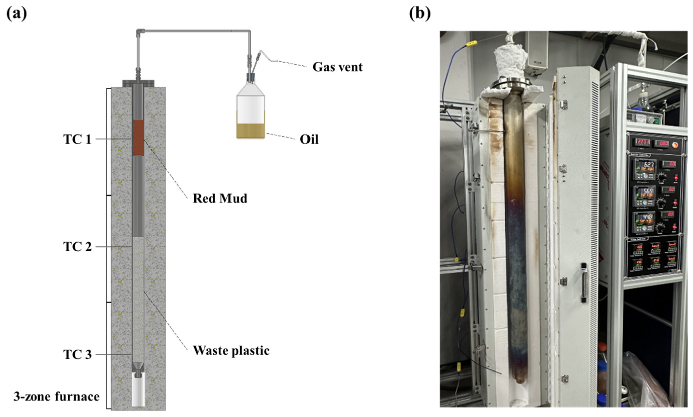
2.1. Experimental Apparatus
2.2. Characterization of Pyrolysis Oil and RM Adsorbents
3. Results
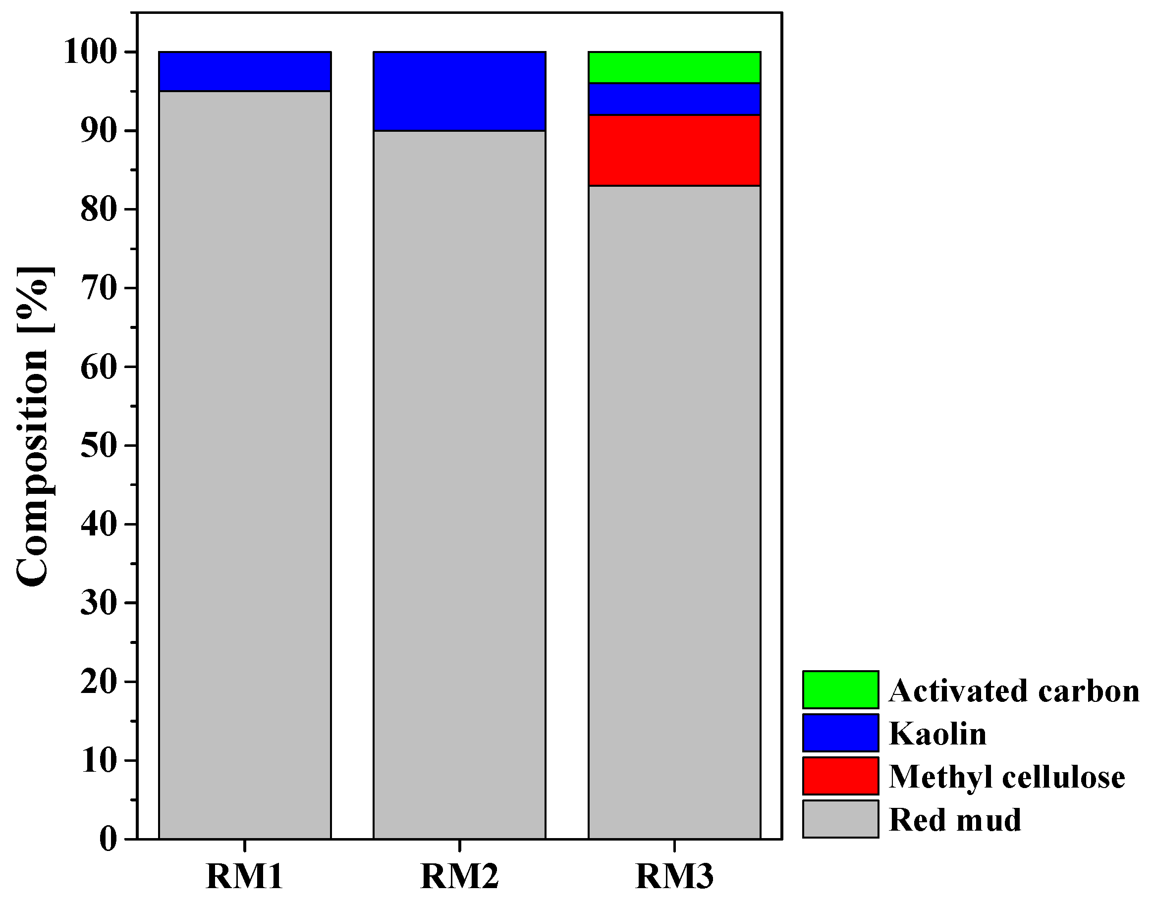
3.1. Characterization of RM Adsorbent
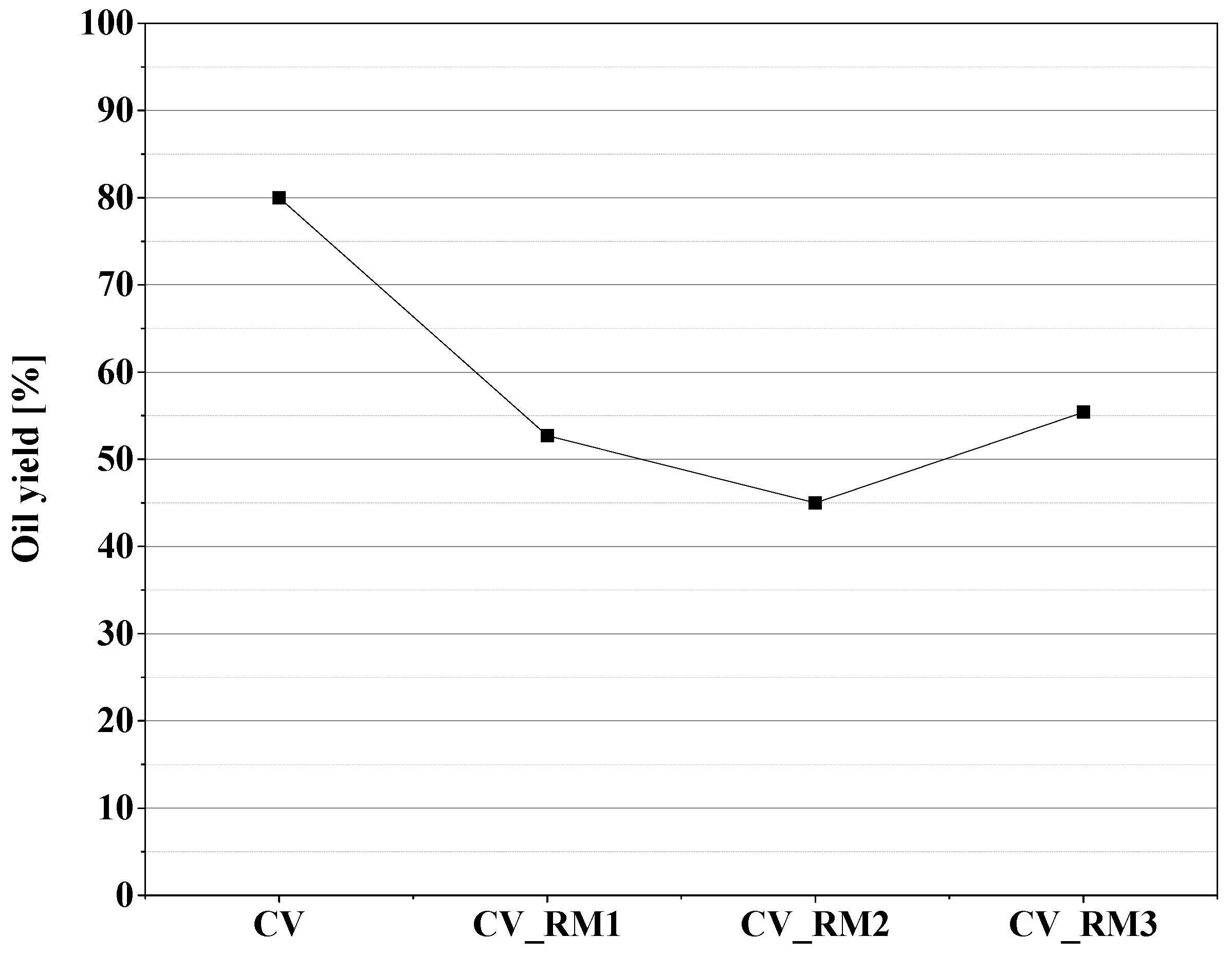
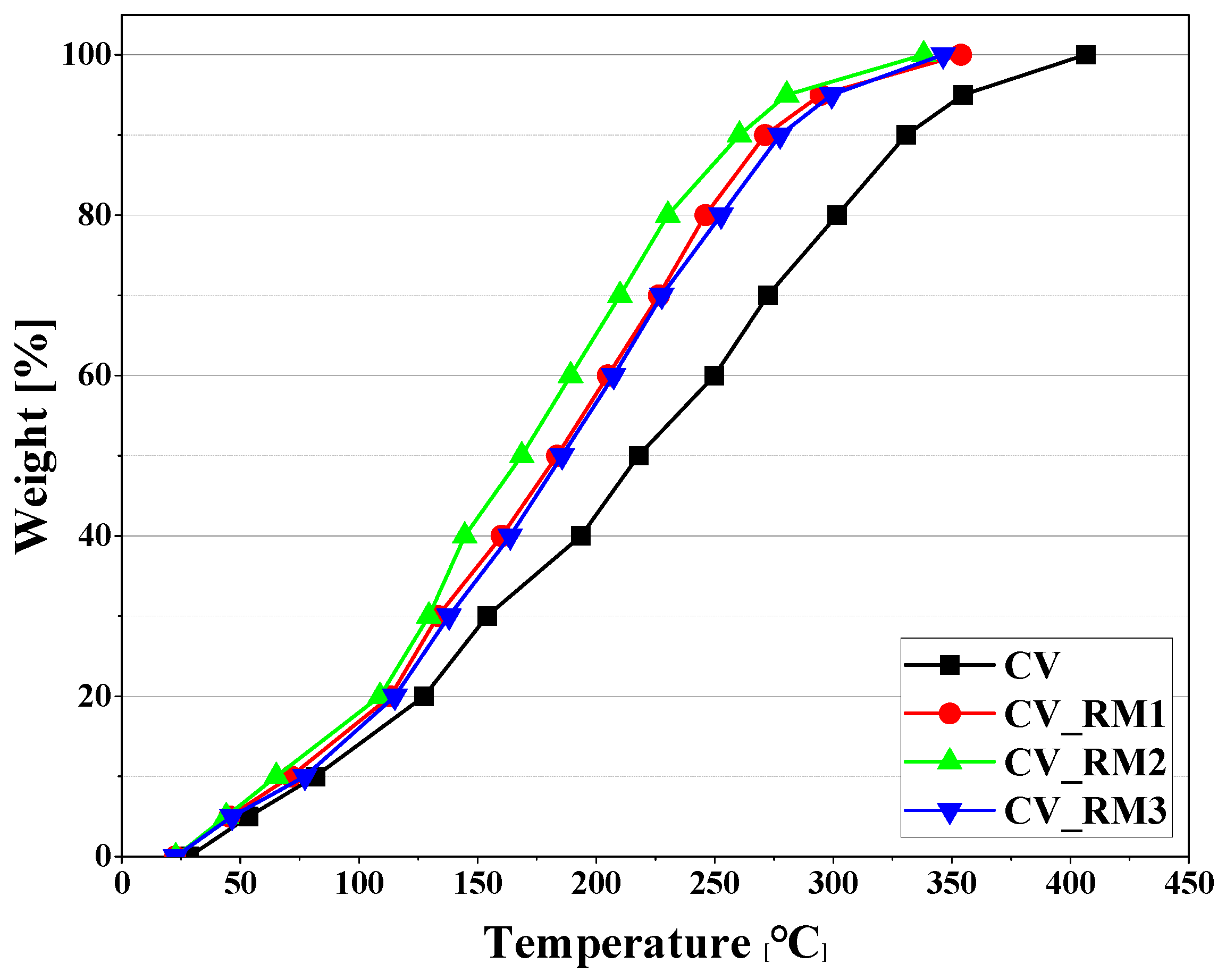
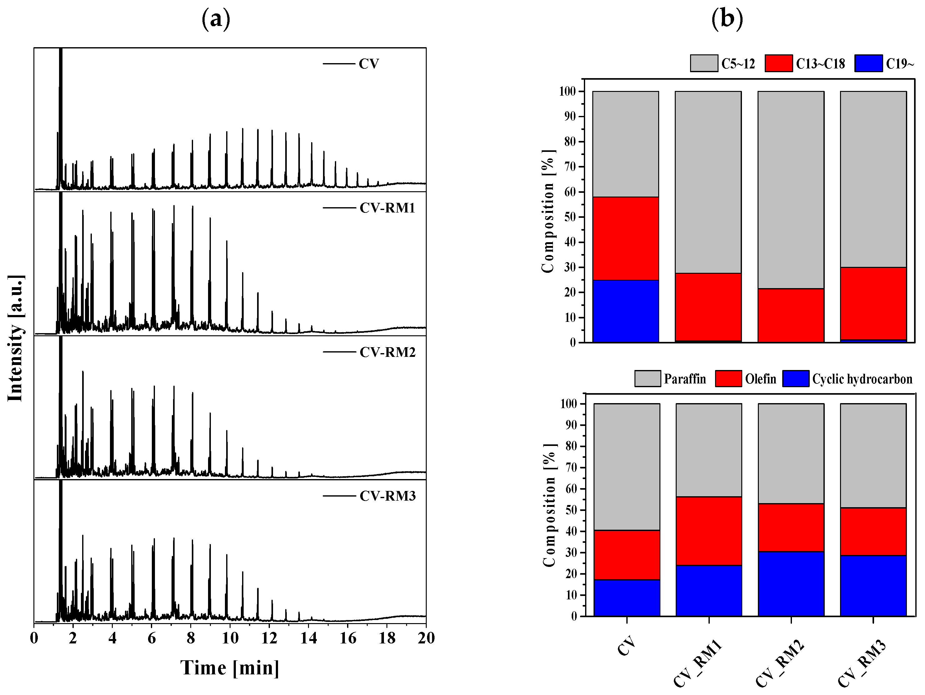
3.2. Upgrading Effect of Red Mud on Pyrolysis Oil
3.3. Chlorine Removal Effect of Red Mud in the Production of Pyrolysis Oil
4. Conclusions
Author Contributions
Funding
Data Availability Statement
Conflicts of Interest
References
- Lopez-Urionabarrenechea, A.; de Marco, I.; Caballero, B.M.; Adrados, A.; Laresgoiti, M.F. Empiric model for the prediction of packaging waste pyrolysis yields. Appl. Energy 2021, 98, 524–532. [Google Scholar] [CrossRef]
- Kiran, N.; Ekinci, E.; Snape, C.E. Recycling of plastic wastes via pyrolysis. Resour. Conserv. Recycl. 2000, 29, 273–283. [Google Scholar] [CrossRef]
- Nielsen, H.P.; Frandsen, F.J.; Dam-Johansen, K.; Baxter, L.L. The implications of chlorine-associated corrosion on the operation of biomass-fired boilers. Prog. Energy Combust. Sci. 2000, 26, 283–298. [Google Scholar] [CrossRef]
- Wang, C.Q.; Zhang, X.; Sun, R.R.; Cao, Y.J. Neutralization of red mud using bio-acid generated by hydrothermal carbonization of waste biomass for potential soil application. J. Clean. Prod. 2020, 271, 122525. [Google Scholar] [CrossRef]
- Yoon, K.; Jung, J.M.; Cho, D.W.; Tsang, D.C.W.; Kwon, E.E.; Song, H. Engineered biochar composite fabricated from RM and lipid waste and synthesis of biodiesel using the composite. J. Hazard. Mater. 2019, 366, 293–300. [Google Scholar] [CrossRef]
- Veses, A.; Aznar, M.; Lopez, J.M.; Callén, M.S.; Murillo, R.; García, T. Production of upgraded bio-oils by biomass catalytic pyrolysis in an auger reactor using low cost materials. Fuel 2015, 141, 17–22. [Google Scholar] [CrossRef]
- Santona, L.; Castaldi, P.; Melis, P. Evaluation of the interaction mechanisms between red muds and heavy metals. J. Hazard. Mater. 2006, 136, 324–329. [Google Scholar] [CrossRef] [PubMed]
- Cengeloglu, Y.; Tor, A.; Ersoz, M.; Arslan, G. Removal of Nitrate from Aqueous Solution by Using Red Mud. Sep. Purif. Technol. 2006, 51, 374–378. [Google Scholar] [CrossRef]
- Li, Y.; Liu, C.; Luan, Z.; Peng, X.; Zhu, C.; Chen, Z.; Zhang, Z.; Fan, J.; Jia, Z. Phosphate removal from aqueous solutions using raw and activated red mud and fly ash. J. Hazard. Mater. 2006, 137, 374–383. [Google Scholar] [CrossRef]
- Li, P.; Miser, D.E.; Rabiei, S.; Yadav, R.T.; Hajaligol, M.R. The removal of carbon monoxide by iron oxide nanoparticles. Appl. Catal. B 2003, 43, 151–162. [Google Scholar] [CrossRef]
- Dhupe, A.P.; Gokarn, A.N.; Doraiswami, L.K. A novel regenerable sorbent for SO2. Chem. Eng. Sci. 1988, 43, 2103–2108. [Google Scholar] [CrossRef]
- Furimsky, E.; Yumura, M. Solid adsorbents for removal of hydrogen sulphide from hot gas. Erdol Kohle-Erdgas-Pertochemie Ver. Mit. Brennst. Chem. Bd. 1986, 39, 163–172. [Google Scholar]
- Hala’sz, J.; Hodos, M.; Hannus, I.; Tasi, G.; Kiricsi, I. Catalytic detoxification of C2-chlorohydrocarbons over iron-containing oxide and zeolite catalysts. Colloids Surf. A 2005, 265, 171–177. [Google Scholar] [CrossRef]
- Song, Y.Y.; Hu, J.W.; Liu, J.Y.; Evrendilek, F.; Buyukada, M. Catalytic effects of CaO, Al3, Fe2O3, and red mud on Pteris vittata combustion: Emission, kinetic and ash conversion patterns. J. Clean. Prod. 2020, 252, 119646. [Google Scholar] [CrossRef]
- Lim, X.Y.; Sanna, A.; Andrésen, J.M. Influence of RM impregnation on the pyrolysis of oil palm biomass-EFB. Fuel 2014, 119, 259–265. [Google Scholar] [CrossRef]
- Liu, Y.; Li, X.; Zhang, W.; Dou, J.; Zhang, Q.; Ma, F.; Gu, Q. Effect and mechanisms of red mud catalyst on pyrolysis remediation of heavy hydrocarbons in weathered petroleum-contaminated soil. J. Environ. Chem. Eng. 2021, 9, 106090. [Google Scholar] [CrossRef]
- Eom, T.K. Improvement of Process and Efficiency of Waste-plastic Emulsion Process. J. Korean Soc. Environ. Technol. 2012, 13, 371–378. [Google Scholar]
- Kaminsky, W. Chemical recycling of plastics by fluidized bed pyrolysis. Fuel Commun. 2021, 8, 100023. [Google Scholar] [CrossRef]
- Choi, S.; Choi, Y.; Jeong, Y.; Han, S.; Nguyen, Q.V. Analysis on the Pyrolysis Characteristics of Waste Plastics Using Plug Flow Reactor Model. New Renew. Energy 2022, 18, 12–21. [Google Scholar] [CrossRef]
- Demirbas, A. Pyrolysis of municipal plastic wastes for recovery of gasoline-range hydrocarbons. J. Anal. Appl. Pyrolysis 2004, 72, 97–102. [Google Scholar] [CrossRef]
- Park, S.; Rana, M.; Shin, D.; Park, J.-H. Lignin Decomposition in Hydrothermal Liquefaction Process using Red-Mud Catalyst. J. Korean Soc. Environ. Eng. 2019, 41, 132–139. [Google Scholar] [CrossRef]
- Junior, E.S.A.; Barata, M.S.; Secco, P.; Carvalho, E.S. The use of red mud and kaolin waste in the production of a new building material: Pozzolanic pigment for colored concrete and mortar. Rev. Mater. 2022, 27, e20220149. [Google Scholar]
- Zainuri, M. Hematite from Natural Iron Stones as Microwave Absorbing Material on X-Band Frequency Ranges. IOP Conf. Ser. Mater. Sci. Eng. 2017, 196, 012008. [Google Scholar] [CrossRef]
- Tammishetti, V.; Joshi, K.; Rai, B.; Pradip. Selective Dispersion—Flocculation of Alumina Rich Iron Ore Samples. XXVI Int. Miner. Process. Congr. (IMPC) 2012, 6, 05401. [Google Scholar]
- Amao, A.O.; Al-Otaibi, B.; Al-Ramadan, K. High-resolution X–ray diffraction datasets: Carbonates. Data Brief. 2022, 42, 108204. [Google Scholar] [CrossRef]
- Hwang, K.-R.; Choi, S.-A.; Choi, I.-H.; Lee, K.-H. Catalytic cracking of chlorinated heavy wax from pyrolysis of plastic wastes to low carbon-range fuels: Catalyst effect on properties of liquid products and dichlorination. J. Anal. Appl. Pyrolysis 2021, 155, 105090. [Google Scholar] [CrossRef]
- Akin, O.; Varghese, R.J.; Eschenbacher, A.; Oenema, J.; Seifali, M.; Abbas-Abadi; Stefanidis, G.D.; Geem, K.M.V. Chemical recycling of plastic waste to monomers: Effect of catalyst contact time, acidity and pore size on olefin recovery in ex-situ catalytic pyrolysis of polyolefin waste. J. Anal. Appl. Pyrolysis 2023, 172, 106036. [Google Scholar] [CrossRef]
- Wang, G.; Jensen, P.A.; Wu, H.; Frandsen, F.J.; Sander, B.; Glarborg, P. Potassium Capture by Kaolin, Part 1: KOH. Energy Fuels 2018, 32, 1851–1862. [Google Scholar] [CrossRef]
- Kumar, S.; Panda, A.K.; Singh, R.K. Preparation and Characterization of Acid and Alkaline Treated Kaolin Clay. Bull. Chem. React. Eng. Catal. 2013, 8, 61–69. [Google Scholar] [CrossRef]
- Kłosek-Wawrzyn, E.; Małolepszy, J.; Murzyn, P. Sintering behavior of kaolin with calcite. Procedia Eng. 2013, 57, 572–582. [Google Scholar] [CrossRef]
- Edomwonyi-Otu, L.C.; Aderemi, B.O.; Ahmed, A.S.; Coville, N.J.; Maaza, M. Influence of thermal treatment on Kankara kaolinite. Opticon1826 2013, 15, 5. [Google Scholar] [CrossRef]
- Heng, S.; Jiu, S.; Li, H. Preparation of Calcined Kaolin by Efficient Decarburization of Coal-Series Kaolinite in a Suspended Bed Reactor. Processes 2022, 10, 2048. [Google Scholar] [CrossRef]
- Lingaiah, N.; Uddin, M.A.; Muto, A.; Imai, T.; Sakata, Y. Removal of organic chlorine compounds by catalytic dehydrochlorination for the refinement of municipal waste plastic derived oil. Fuel 2001, 80, 1901. [Google Scholar] [CrossRef]
- Torres, D.; Jiang, Y.; Sanchez Monsalve, D.A.; Leeke, G.A. Chlorine removal from the pyrolysis of urban polyolefinic waste in a semi-batch reactor. J. Environ. Chem. Eng. 2021, 9, 104920. [Google Scholar] [CrossRef]


 : oxygen content of RM,
  : oxygen content of CV_RM,
  : chlorine content of RM,
  : chlorine content of CV_RM).
: oxygen content of RM, : oxygen content of CV_RM, : chlorine content of RM, : chlorine content of CV_RM).
: chlorine content of CV_RM).
: oxygen content of RM, : oxygen content of CV_RM, : chlorine content of RM, : chlorine content of CV_RM).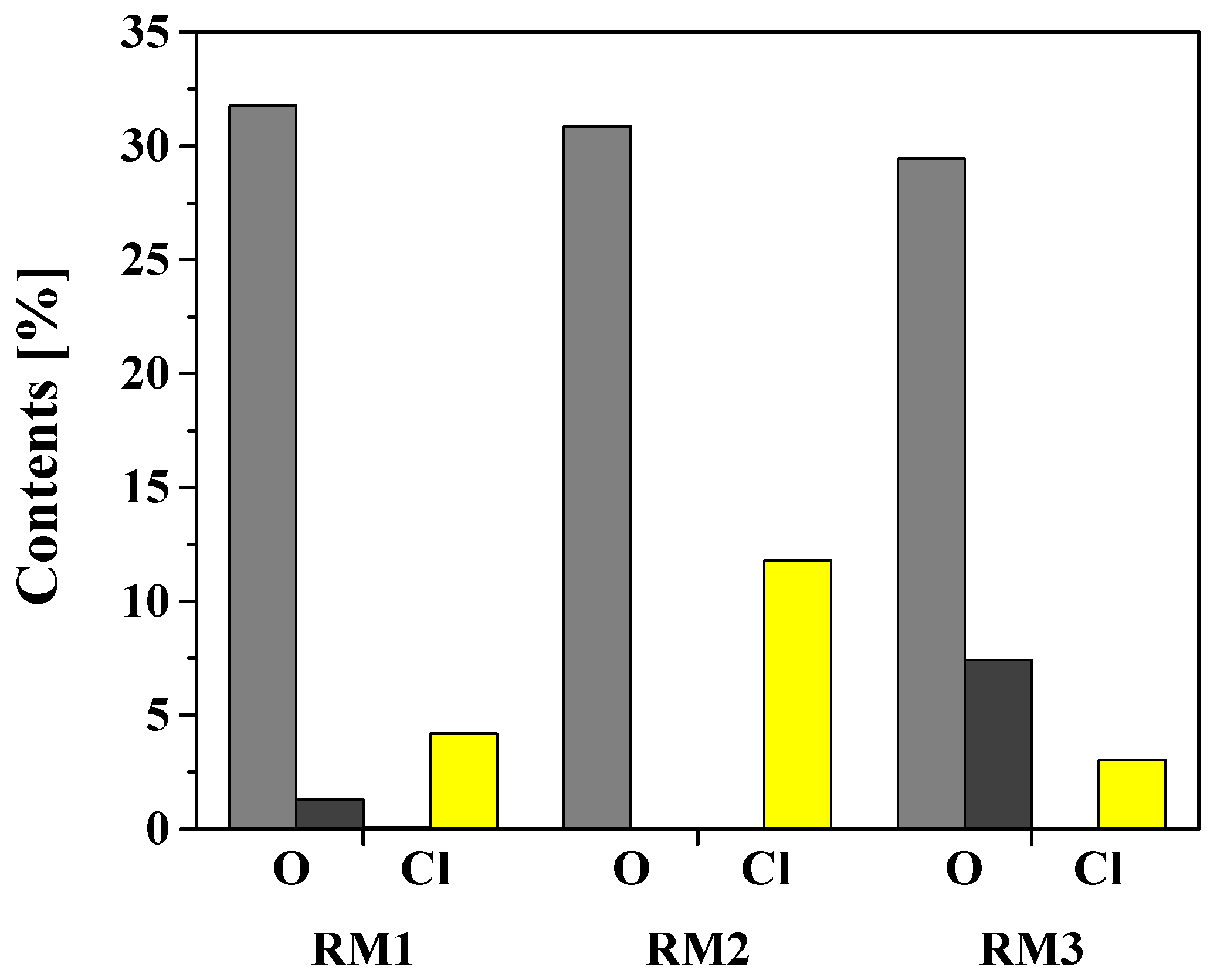

| RM1 | RM2 | RM3 | |
|---|---|---|---|
| Fe | 49.4 | 47.9 | 48.2 |
| Al | 14.2 | 14.6 | 14.0 |
| Si | 7.9 | 10.2 | 8.0 |
| Ti | 8.6 | 8.4 | 8.4 |
| Ca | 9.8 | 9.9 | 9.4 |
| Na | 5.0 | 5.1 | 5.0 |
| C | 2.0 | 1.9 | 4.0 |
| Other | 3.1 | 2.0 | 3.0 |
| Adsorbents | RM1 | RM2 | RM3 | |
|---|---|---|---|---|
| BET | Surface Area (m2/g) | 19.72 | 20.49 | 23.92 |
| Pore Volume (cm3/g) | 0.03 | 0.03 | 0.04 | |
| t-Plot Micropore Area (m2/g) | 1.3508 | 1.2890 | 3.5703 | |
| BJH Desorption cumulative volume (cm3/g) | 0.03188 | 0.03344 | 0.03954 | |
| Pore Size (nm) | 6.13 | 6.14 | 6.52 | |
| Acidity (mmolNH3/g) | Weak (<300 °C) | 0.01 | 0.03 | 0.01 |
| Strong (>500 °C) | 0.11 | 0.12 | 0.37 | |
| Total | 0.12 | 0.15 | 0.39 | |
| CV_RM1 | CV_RM2 | CV_RM3 | |
|---|---|---|---|
| Surface Area (m2/g) | 5.8026 | 5.5067 | 8.6391 |
| Pore Volume (cm3/g) | 0.0062 | 0.0059 | 0.0113 |
| t-Plot Micropore Area (m2/g) | 0 | 0 | 0 |
| BJH Desorption cumulative volume (cm3/g) | 0.00622 | 0.00592 | 0.01128 |
| Pore Size (nm) | 4.9576 | 5.5795 | 6.3015 |
Disclaimer/Publisher’s Note: The statements, opinions and data contained in all publications are solely those of the individual author(s) and contributor(s) and not of MDPI and/or the editor(s). MDPI and/or the editor(s) disclaim responsibility for any injury to people or property resulting from any ideas, methods, instructions or products referred to in the content. |
© 2025 by the authors. Licensee MDPI, Basel, Switzerland. This article is an open access article distributed under the terms and conditions of the Creative Commons Attribution (CC BY) license (https://creativecommons.org/licenses/by/4.0/).
Share and Cite
Kim, H.S.; Kim, H.-J.; Kim, J.; Kim, J.-H.; Kang, T.-J.; Kang, S.-H.; Lee, Y.; Lee, S.C.; Chang, C.-S.; Bae, J.W. Research on the Chlorine Removal and Upgrading of Waste Plastic Pyrolysis Oil Using Iron-Based Adsorbents. Energies 2025, 18, 3434. https://doi.org/10.3390/en18133434
Kim HS, Kim H-J, Kim J, Kim J-H, Kang T-J, Kang S-H, Lee Y, Lee SC, Chang C-S, Bae JW. Research on the Chlorine Removal and Upgrading of Waste Plastic Pyrolysis Oil Using Iron-Based Adsorbents. Energies. 2025; 18(13):3434. https://doi.org/10.3390/en18133434
Chicago/Turabian StyleKim, Hyo Sik, Hyun-Ji Kim, Jihyeon Kim, Jin-Ho Kim, Tae-Jin Kang, Suk-Hwan Kang, Yeji Lee, Soo Chool Lee, Chi-Seong Chang, and Jong Wook Bae. 2025. "Research on the Chlorine Removal and Upgrading of Waste Plastic Pyrolysis Oil Using Iron-Based Adsorbents" Energies 18, no. 13: 3434. https://doi.org/10.3390/en18133434
APA StyleKim, H. S., Kim, H.-J., Kim, J., Kim, J.-H., Kang, T.-J., Kang, S.-H., Lee, Y., Lee, S. C., Chang, C.-S., & Bae, J. W. (2025). Research on the Chlorine Removal and Upgrading of Waste Plastic Pyrolysis Oil Using Iron-Based Adsorbents. Energies, 18(13), 3434. https://doi.org/10.3390/en18133434