Review

Progress in Materials and Metal Substrates for Solid Oxide Fuel Cells

1
Department of Chemical Engineering, College of Engineering, Wonkwang University, Iksan 54538, Jeonbuk, Republic of Korea
2
ICT Fusion Green Energy Research Institute, Wonkwang University, Iksan 54538, Jeonbuk, Republic of Korea
Energies 2025, 18(13), 3379; https://doi.org/10.3390/en18133379
Submission received: 28 May 2025 / Revised: 19 June 2025 / Accepted: 25 June 2025 / Published: 27 June 2025

Abstract

Solid oxide fuel cells (SOFCs) have been considered as alternative energy conversion devices because of their high energy conversion efficiency, fuel flexibility, and cost efficiency without precious metal catalysts. In current SOFCs, the cermet anode consists of nickel and ion-conducting ceramic materials, and solid oxide electrolytes and ceramic cathodes have been used. SOFCs normally operate at high temperatures because of the lower ion conductivity of ceramic components at low temperatures, and they have weaknesses in terms of mechanical strength and durability against thermal shock originating from the properties of ceramic materials. To solve these problems, metal-supported solid oxide fuel cells (MS-SOFCs) have been designed. SOFCs using metal substrates, such as Ni-based and Cr-based alloys, provide significant advantages, such as a low material cost, ruggedness, and tolerance to rapid thermal cycling. In this article, SOFCs are introduced briefly, and the types of metal substrate used in MS-SOFCs, as well as the advantages and disadvantages of each metal support, are reviewed.

1. Introduction

A fuel cell is an electrochemical device that converts chemical energy directly into electrical energy with high efficiency. Christian Friedrich Schönbein discovered the basic operating principle of a fuel cell in 1838. Sir William Grove demonstrated the first fuel cell using a diluted sulfuric acid electrolyte, a hydrogen–platinum anode, and an oxygen–platinum cathode in 1838. In 1932, Francis Thomas Bacon invented and patented the Bacon cell, which consists of an alkaline electrolyte, a nickel anode, and a lithium-doped nickel oxide cathode. A fuel cell generates electricity inside the cell through the reaction of fuel and oxidizer. The fuel is oxidized to generate electrons at the anode side of the cell, and the generated electrons flow to the cathode through an external circuit and ionize the oxidizer. The ionized oxidizer diffuses through the electrolyte by ion diffusion toward the anode, where it meets the fuel. Despite their long history, fuel cells still attract considerable attention as a sustainable energy source, not only as a reliable electric power generation system for portable and transportable purposes but also as a stationary power generator with unlimited potential [1]. Depending on the electrolyte, fuel cells are classified into polymer electrolyte fuel cells (PEFCs), phosphoric acid fuel cells (PAFCs), molten carbonate fuel cells (MCFCs), alkaline fuel cells (AFCs), and solid oxide fuel cells (SOFCs). Fuel cells can be classified as high- and low-temperature fuel cells depending on their operating temperature. High-temperature fuel cells, such as MCFCs and SOFCs, operate at temperatures higher than 900 K, whereas the operating temperatures of AFCs, PAFCs, and PEFCs are lower than 473 K.
Among these fuel cells, SOFCs are classified as third-generation fuel cells and generally use ceramic electrolytes, which are oxygen ion conductors [2,3]. SOFCs generally operate at relatively high temperatures when the electrolyte has sufficiently high ionic conductivity. The oxygen ions generated at the cathode by the reduction of oxygen move from the cathode to the anode through the electrolyte and react with the fuel. At the same time, electrons move in the opposite direction to the oxygen ions, that is, from the anode to the cathode, to generate electrical energy. Because of the reaction, electrical energy is generated as a small amount of byproducts, such as water, heat, and/or CO2, which are generated when hydrocarbons are used as fuel. SOFCs are considered promising next-generation power generators because of their fuel flexibility, high energy conversion efficiency, and simple internal reforming system [4]. The advantage of a high operating temperature that allows internal reforming is that it promotes fast electrocatalytic reactions. Using such an internal reforming system simplifies the system and reduces the cost. In addition, non-precious metal materials are used as electrodes, which makes possible a combined energy generation system of heat and electricity; accordingly, the efficiency of SOFCs, which reaches as much as 70%, can be increased further by 20% using the combined heat method. In addition, because of the high temperature of the exhaust heat, the bottoming cycle, i.e., combination with a gas or steam turbine system, is also considered, and an extremely high energy conversion efficiency from fuel to electricity can be achieved.
Currently, research on SOFCs is mainly being conducted using electrolyte-supported cells, which use the electrolyte layer as a mechanical support for the thin anode and cathode layers. Electrolyte-supported cells can obtain stable power at high operating temperatures; however, the performance deteriorates significantly when the operating temperature is lowered by increasing the internal resistance of the electrolyte. Therefore, electrolyte-supported cells generally operate at temperatures of 1073–1273 K. However, such high-temperature operation requires careful thermal management and imposes limitations on the electrode materials. Therefore, research has been conducted on the use of electrode supports to reduce the internal resistance of electrolyte by reducing its thickness. The electrode-supported electrolyte is generally thinner than 50 µm, and the electrode-supported cell shows higher power generation characteristics than the electrolyte-supported cell owing to the small internal resistance of the electrolyte, even at lower operation temperature. However, because electrode- and electrolyte-supported SOFCs both use ceramic materials or cermet as substrates, the low mechanical strength and thermal expansion characteristics of ceramics or cermet limit the applications of SOFCs. To solve these problems and reduce the price of SOFCs, research has been conducted on metal-supported solid oxide fuel cells (MS-SOFCs) that use metal substrates. In this review, the components of SOFCs are summarized comprehensively, and the achievements and characteristics in MS-SOFCs are summarized according to the elements of the metal substrates.

2. Materials for Solid Oxide Fuel Cells

Owing to their high operating temperatures, SOFCs require materials with various properties for use as electrolytes, anodes, and cathodes. Currently, all components in SOFC systems are composed of ceramic or ceramic-based cermet, and all components have functions such as chemical and physical stability in the corresponding chemical environment, chemical compatibility with other components, sufficient conductivity, and similar thermal expansion coefficients (TECs) to those of other components. The specific characteristics of the components used in SOFCs are as follows.

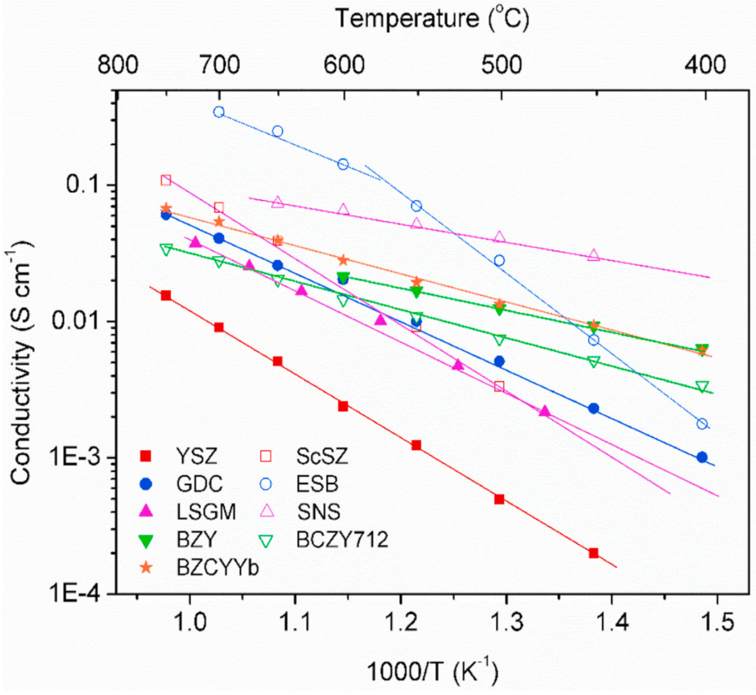
2.1. Electrolyte Materials of SOFCs

The main function of the electrolyte is to conduct ions. The oxygen ions generated at the cathode move to the low oxygen partial pressure region (anode) in the reaction mechanism of the SOFC using an oxygen ion-conducting electrolyte. The major requirements for the electrolyte are as follows.
  • Stability: The electrolyte must be chemically and morphologically stable under dual atmospheres, i.e., H2 and O2.
  • Conductivity: The electrolyte must have appropriate ionic conductivity. To minimize ohmic losses, the ionic conductivity must be as high as possible. The electrolyte must also have negligible electronic conductivity to avoid voltage loss.
  • Compatibility: The electrolyte must be chemically compatible with other battery components during manufacturing as well as during operation.
  • Thermal expansion: The thermal expansion of the electrolyte must be similar to that of the other battery components to avoid cracking and delamination during manufacturing and operation, including thermal cycling.
  • Porosity: The electrolyte must be dense to prevent cross-linking of the reactants and to maximize conductivity.
Figure 1 is a graph showing the ion conductivity according to the temperatures of various SOFC electrolyte materials [5]. The most common electrolyte in existing SOFCs is zirconia (ZrO2) stabilized with a heteroelement, such as yttria (Y2O3) [6,7,8,9]. Pure ZrO2 is monoclinic at room temperature but shows a phase transition to a tetragonal structure at temperatures of more than 1423 K. Yttria shows high solubility in ZrO2, and zirconia stabilized with yttria (YSZ) maintains a cubic fluorite structure from room temperature to its melting point (2923 K). The crystal arrangement of ZrO2 has two oxygen ions for every zirconium ion, whereas Y2O3 has only 1.5 oxygen ions for every yttrium (Y) ion. Therefore, the concentration of oxygen ion vacancies is increased by stabilization, thereby increasing the ionic conductivity. YSZ has pure oxygen ion conductivity with no electronic conductivity, is highly stable in both oxidizing and reducing atmospheres, and has no reactivity with the other components used in SOFCs. However, low ionic conductivity at low temperatures decreases the performance of SOFCs. Therefore, temperatures above 1073 K are generally required for operation. However, such high operating temperatures decrease the durability of other components, such as the anode and cathode.
Another material that has attracted significant attention as an electrolyte is lanthanum gallate (LaGaO3), which is a perovskite oxide [10,11]. Lanthanum gallate has attracted much attention as an alternative electrolyte for SOFCs operating at low temperatures, and the most preferred composition in doped LaGaO3 is La0.9Sr0.1Ga0.8Mg0.2O2.85 (LSGM). The ionic conductivity of LSGM is significantly higher than that of YSZ at intermediate temperatures (573–973 K). However, LSGM has some disadvantages, such as reactivity with other components, and some secondary phases, such as La4Ga2O9 and SrLaGa3O7, having lower conductivities that are generated by the reaction between the LSGM electrolyte and electrode materials.
In the past decade, various materials with excellent oxygen ion conductivities at low temperatures have been studied as electrolytes to lower the operating temperatures of SOFCs. Ce-based oxygen ion conductors, such as Gd-doped CeO2 (GDC), exhibit high ion conductivity at low temperatures [12]. However, ceria is partially reduced to Ce3+, making the doped ceria a mixed conductor. Therefore, the open-circuit voltage is reduced, and the fuel consumption that does not produce power also lowers the system efficiency.
In addition, a study on low-temperature SOFCs using Bi2O3 doped with Er, Y, and Zr as an electrolyte was reported recently. The triple-doped Bi2O3 electrolyte simultaneously showed 147 times higher ionic conductivity than the commercial YSZ electrolyte at 873 K [13]. Bismuth oxide has been considered as an electrolyte material for SOFCs since Takahashi et al. first reported the results of a study on the ionic conductivity of Bi2O3 containing SrO in 1972 owing to its high oxygen ion conductivity [14]. However, its wide application as an electrolyte is limited by the decomposition of the material at low oxygen partial pressure and high reactivity. In contrast, triple-doped Bi2O3 has excellent stability for 1000 h and is considered an alternative electrolyte for low- and intermediate-temperature SOFCs.
Although various oxygen ion-conducting ceramic materials are used as electrolyte materials for intermediate-temperature SOFCs, the oxygen ion conductivity of electrolytes generally decreases rapidly owing to the high activation energy (Ea) of the oxygen ion conductor. Recently, proton ion conductors with high ion conductivity, even at low temperatures, have attracted much attention. Proton-conducting oxides have high proton conductivity, offering important advantages such as lower activation energy and higher fuel efficiency at intermediate temperatures. The representative ion conduction mechanisms of proton-conducting ceramics are the “vehicle mechanism” and “Grotthuss mechanism.” In the vehicle mechanism, protons are conducted by the movement of OH– through oxygen vacancies, whereas in the Grotthuss mechanism, hydrogen ions are conducted by the reorientation of OH– and the transfer of protons between nearby oxygen ions [15]. In the 1980s, perovskite-structured proton-conducting materials were reported. In 1980, Iwahara et al. discovered that perovskite-structured SrZrO3 has high high-temperature proton conductivity [16] and reported that SrCeO3 exhibited proton conductivity when exposed to an atmosphere containing water or hydrogen [17,18].
Research results on barium cerate (BaCeO3) and barium zirconate (BaZrO3) using Ba at site A have also been reported [19,20,21,22,23]. BaCeO3-based materials demonstrate excellent proton conductivity through proton absorption and transport through the lattice structure in H2O environments [19]. However, the chemical instability of BaCeO3 in CO2 atmospheres restricts its long-term stability [20]. To enhance stability, BaZrO3 is an attractive material for electrolytes. It is chemically stable in CO2-rich environments but has a lower proton conductivity owing to its higher activation energy for proton transport [21]. Therefore, the co-doping (Ce and Zr) strategy achieved a balance between chemical stability and high proton conductivity, making it a promising candidate for PCFCs [22]. In addition, the incorporation of yttrium stabilizes the cubic perovskite structure and forms oxygen vacancies that facilitate proton migration. BaZr(Ce,Y)O3 (BZCY) is one of the most widely studied proton conductors because BZCY includes the advantages of both barium cerate (BaCeO3) and barium zirconate (BaZrO3) [23].

2.2. Cathode Materials of SOFCs

The main reaction at the cathode is the reduction of the oxidant, which consists of the reduction of molecular oxygen, transfer of charged species to the electrolyte, and current distribution associated with the oxygen reduction reaction. The main requirements for SOFC cathodes are as follows:
  • High electronic conductivity (more than 100 S/cm);
  • High oxygen ion conductivity;
  • High catalytic activity for oxygen molecular adsorption and dissociation and for oxygen reduction;
  • A TEC that matches those of the other cell components;
  • Sufficient porosity to transport gases to the reaction site.
At high operating temperatures, the cathode reaction occurs rapidly, and (La,Sr)MnO3 (LSM) is used as the cathode material in conventional SOFC systems. LSM is a well-known pure electronic conduction material with high electrical conductivity and high chemical stability in oxidation atmospheres at high temperatures [24]. In pure electronic conduction LSM, the oxygen reduction reaction occurs at the limited narrow triple-phase boundary (TPB, air–cathode–electrolyte interface). Although LSM shows excellent cathodic properties in SOFCs using an YSZ electrolyte at high operating temperatures, it has the problem that the La2Zr2O7 insulating phase is formed as a secondary phase by the reaction with YSZ [25]. In addition, lowering the operating temperature of SOFCs increases the irreversibility of the oxygen reduction reaction and the polarization loss in LSM owing to the charge transfer step, which reduces the oxygen ion conductivity.
Therefore, the development of alternative cathodes with excellent catalytic properties at medium and low temperatures has attracted much attention. Moreover, mixed-ion electrochemical conductors (MIECs) have attracted considerable attention recently as promising cathode materials. Cobalt-based perovskite materials, such as (LnSr)CoO3−δ (Ln: La, Pr, Sm, Ba), (LaSr)(CoFe)O3−δ, and (BaSr)(CoFe)O3−δ, are considered excellent alternatives for cathode materials [26,27,28,29]. The partial substitution of A-site cations by lower valence state cations increases the oxygen vacancies in the perovskite, and increases in the oxygen vacancies enhance ionic conductivity with better catalytic properties. In addition, the substitution of ions with similar sizes but lower valences at the B-sites also can be used to adjust the concentration of oxygen vacancies. Therefore, the partial substitution in the A-site and B-site results in high ionic conductivity because of the high concentration of oxygen vacancies and good electronic conductivity resulting from the mixed valence states. However, the Cobalt-based perovskite oxide materials have higher TEC (TEC of La0.8Sr0.2CoO3-δ: 1.91 × 10⁻⁵/K, TEC of Ba0.5Sr0.5Co0.8Fe0.2O3-δ: 2.00 × 10⁻⁵/K) than that of LSM (1.18 × 10⁻⁵/K). Therefore, studies on Co-free cathode materials such as La0.8Sr0.2FeO3-δ (1.22 × 10⁻⁵/K) and La0.6Ca0.4Fe0.8Ni0.2O3-δ (1.12 × 10⁻⁵/K), which have similar TEC to electrolyte materials, have been reported [30,31]. However, Co-free cathode materials require further investigation due to their low catalytic activity and conductivity.
Ruddlesden–Popper phases, with the general formula An+1BnO3n+1, have attracted considerable attention because of the large free volume in the crystal lattices, high electric conductivity, and oxygen migration mechanism [32]. The structure consists of ABO3 perovskite layers sandwiched between two AO rock salt layers. The structure consists of an alternating series of connected perovskite and rock salt blocks that makes it possible for the interstitial oxygen atoms located in the rock salt layer to migrate. The n = 2 and n = 3 phases have performed well as cathode materials in SOFCs when the optimization of the microstructure is considered [33,34,35]. The Lan+1NinO3n+1 Ruddlesden–Popper phases exhibited higher TEC (TEC of La2NiO4.15: 1.38 × 10⁻⁵/K, TEC of La3Ni2O6.95: 1.32 × 10⁻⁵/K, TEC of La4Ni3O9.78: 13.1 × 10⁻⁵/K) than that of electrolyte materials (TEC of LSGM: 1.09 × 10⁻⁵/K, TEC of SDC: 1.18 × 10⁻⁵/K, TEC of YSZ: 1.05 × 10⁻⁵/K) [34]. By increasing n, the TEC of Lan+1NinO3n+1 is decreased, and the long-term stability (at 1073 K) is improved. Therefore, the catalytic activity of materials depends on the A-site ions and the alio-valence number of ions. The n = 1 phases, such as La2NiO4.15, have concerns regarding lower performance and stability; to solve these problems, the doping effect at the B-site was investigated [36].
The LnBaMO5+δ (Ln = Pr, Nd, Sm, and Gd, M = Co, Fe, Ni, Cu, etc.) layered perovskite oxides have also been considered as an alternative cathode material for intermediate temperature because of their much higher chemical diffusion and surface exchange coefficients compared with those of ABO3 simple perovskite oxides. Cobalt-containing layered oxides exhibit faster oxygen ion diffusion and surface exchange kinetics owing to their very low area-specific resistance and good cell performance [37]. Some research groups have investigated the influence of dopants at the A-sites of perovskites on the electrical conductivity and oxygen reduction reaction. However, some drawbacks, such as redox instability and the formation of a secondary phase, e.g., BaCO3 or SrCO3, arise from the reaction with CO2 in the atmosphere [38]. The segregation of the dopant and formation of the secondary phase originated from the size mismatch between the host and dopant cations [39]. Among the cation dopants, Ca, which has an ion size similar to that of Ba, can suppress surface segregation, resulting in better long-term stability of the cathode [40]. However, cathode materials using Co as the B-site have inadequate thermal and chemical compatibilities with electrolytes, and their high costs inhibit their wide application in SOFCs [41]. The LnBaCo2O5+δ layered perovskite oxide usually show very high TECs (1.76–2.15 × 10⁻⁵/K) because of the presence of cobalt ions. Therefore, double perovskites using Fe instead of Co have been investigated. Fe-based double perovskites exhibit more-stable chemical compatibility than Co-based double perovskites but inferior electrochemical properties, such as the number of oxygen vacancies, species of oxygen, and oxygen transport properties, compared with Co-based materials [42].
Many studies have been conducted to solve the problems of delamination due to high TEC of cathode materials and performance degradation due to sintering reaction that occurs during long-term operation. In the past decade, Swedenborgite-type YBaCo4O7+δ-based oxides have also been considered as alternative cathode material by their low TECs (0.8–1.0 × 10⁻⁵/K) [43,44,45,46]. However, due to their low conductivity, they are used in composites with existing cathode materials rather than being used alone as cathode materials.

2.3. Anode Materials of SOFCs

The main reaction at the anode in SOFCs is the electrochemical oxidation of fuel. The anode material must be stable in a reducing atmosphere and have sufficient electronic conductivity and catalytic activity for the fuel gas reaction under operating conditions. Therefore, various metal catalysts have been considered as anode materials. When the electrochemical activities of Mn, Fe, Co, Ni, Ru, and Pt were compared, Ni was found to have the highest activity for H2 reduction [47]. The anode material must have both high electrochemical activity and the following properties:
  • Sufficiently high electronic conductivity (>100 S/cm) in a reducing environment at the operating temperature;
  • Oxygen ion conductivity (enhanced mixed conductivity);
  • High catalytic activity for hydrogen molecules or fuel adsorption and dissociation, and electrochemical oxidation of fuel;
  • TECs matching those of the other cell components;
  • Sufficient porosity to enable gas to move to the reaction site.
However, pure Ni anodes have several disadvantages, such as a larger TEC than that of the electrolyte and instability in an oxidizing atmosphere. In addition, at temperatures higher than 1623 K, Ni reacts with LSGM to form insulating structures (LaSrGa(Ni)O4 and LaNiO4). Therefore, cermet, which is a mixture of NiO and an ion conductor, is typically used as the anode material. Such cermet anodes have excellent catalytic activity and stability. In addition, the thermal expansion mismatch is reduced, and the TPB is expanded by using a cermet anode. The reduction of NiO in a moist hydrogen or fuel atmosphere produces a porous cermet structure with metallic nickel particles on the pore surfaces. After reduction, the cermet anode consists of a well-developed ion conductor framework and an internal porous space, which introduces a long TPB for the catalytic reaction and provides electronic conduction from the TPB to the current collector by the Ni metal [48]. Therefore, Ni-based cermet anodes are commonly used in SOFCs and satisfy most anode requirements. However, the Ni particles in the cermet anode have an agglomeration problem during long-term operation, resulting in poor durability [49]. In addition, Ni-based cermet is easily deactivated during operation because of its sensitivity to carbon buildup from the incomplete oxidation of hydrocarbons and sulfur poisoning when operating with hydrocarbon fuel [50].
To overcome these shortcomings of cermet anodes, mixed oxide ion electron-conducting ceramic anodes, such as doped SrTiO3 [51], La1−xSrxMn1−yMyO3 (M = Sc, Ti, and Cr) [52,53,54], La1−xSrxFe1−yMnyO3 [55,56], Pr0.8Sr1.2(Co,Fe)0.8Nb0.2O4 [57], and double perovskite Sr2MxMo1−xO6 (M = Mg, Fe) [58,59], have been investigated. These ceramic anode materials exhibited stable performance under anodic operating conditions and demonstrated improved tolerance to carbon and sulfur poisoning under various fuel conditions. However, owing to their lower catalytic activity and electrical conductivity, the power densities of cells using these ceramic anodes are much lower than those of conventional cermet anodes. Therefore, metal catalysts have been used to enhance the power generation properties of SOFC with ceramic anodes. However, the layered perovskite RBaMn2O5+δ (R = Pr and Nd) exhibits high electrical conductivity, as well as excellent redox and coking tolerance and sulfur tolerance [60,61]. Despite these advantages, layered perovskite anodes have issues with regard to the formation of secondary phases by reacting with some electrolyte materials at high temperatures and relatively low catalytic activity compared with that of cermet electrodes.

3. Metal-Supported Solid Oxide Fuel Cells

As discussed in Section 2, various new materials are being studied as electrolyte and electrode materials for SOFCs to improve their performance and reduce their operating temperatures. However, if the low physical strength of ceramic materials, which is a disadvantage, cannot be overcome, the use of SOFCs in various fields will be limited. Therefore, MS-SOFCs have attracted considerable attention because of their high mechanical strength, fast startup, uniform temperature, and high thermal cycling resistance. Williams and Smith first reported the concept of MS-SOFCs in 1969 [62]. They fabricated a zirconia-based electrolyte on a pre-sintered austenitic stainless steel support using flame spraying. MS-SOFCs have been prepared on supports with various metal compositions, including Ni-based materials (such as Ni, NiFe, and NiCrAlY) and ferritic stainless steels. To make rapid thermal cycling in MS-SOFCs possible, it is desirable to match the TEC of the metal substrate with that of the electrolyte. In addition, to achieve enhanced long-term stability, the reactivity between the metal substrate and other constituent materials must be considered. Many researchers have conducted experiments on MS-SOFCs using various metal supports; in this section, they are examined in detail by classifying them according to the composition of the metal substrate.

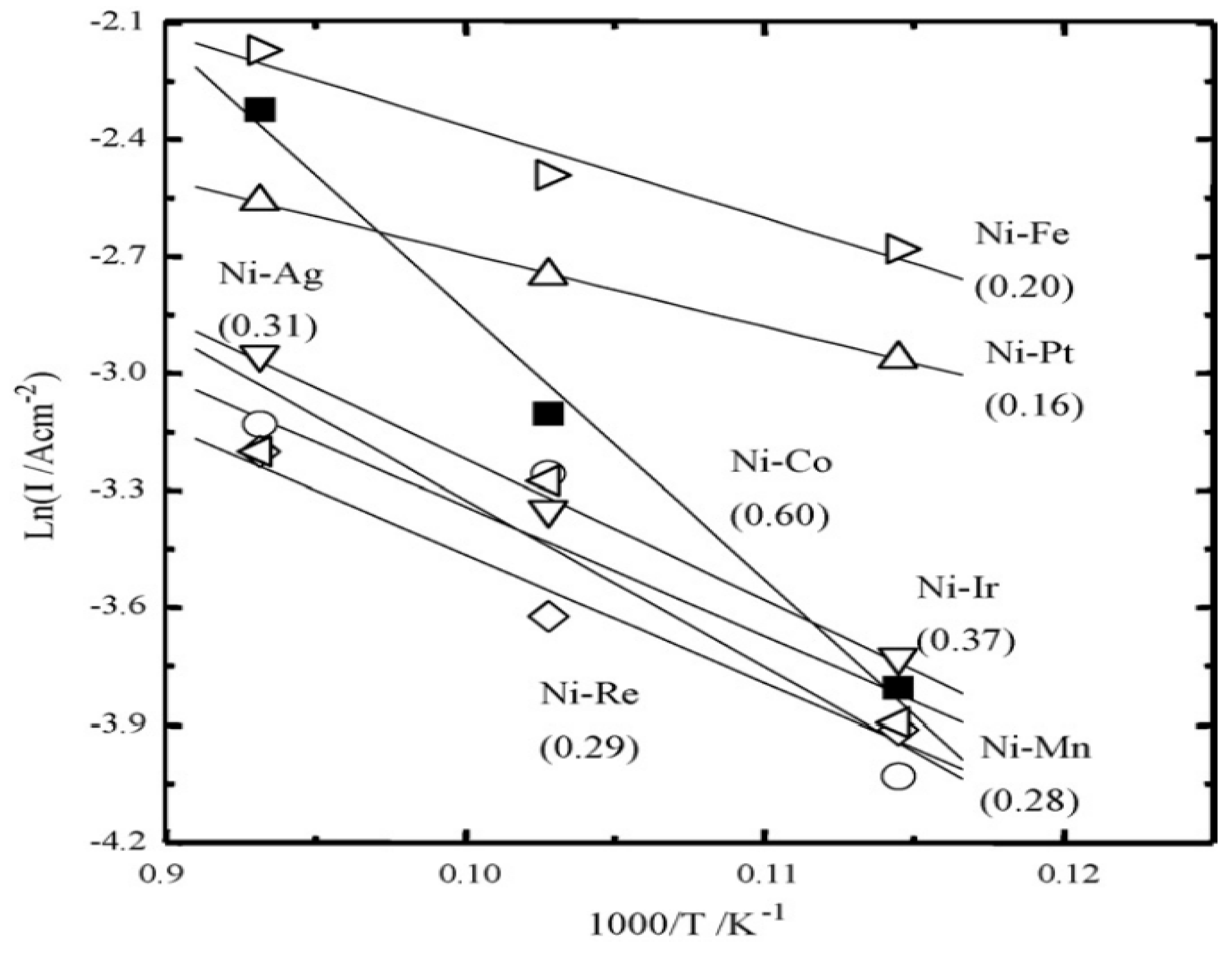
3.1. Ni-Based Metal Substrate

In early studies, a porous NiCrAlY alloy prepared through powder metallurgy was used as a support because of its excellent resistance to high-temperature oxidation and corrosion. On the NiCrAlY substrate, a YSZ electrolyte layer was prepared by plasma spray coating, and a cathode layer was prepared by flame spraying [63,64]. Even though the cell used a thick YSZ electrolyte (more than 120 µm), the cells exhibited sufficient power generation properties (500 mW/cm2 at 1223 K) and excellent durability. In these MS-SOFCs, metallic Ni produced by the reduction of NiO was used as the anode material.
As mentioned in Section 2.3, Ni has been considered as an anode material for SOFCs because of its high electrical conductivity and excellent catalytic properties. Therefore, MS-SOFCs using porous pure Ni-based substrates have been fabricated using various coating methods to obtain excellent electrochemical performance, even at low operating temperatures [65,66,67,68]. Ogumi et al. fabricated dense YSZ thin films on NiO pellets and partially oxidized Ni wire substrates using electrochemical vapor deposition (EVD) and confirmed that metallic Ni was formed by the reduction of NiO during the deposition process [65]. In addition, a study was conducted to convert a tubular dense Ni tube into a porous metal tube through a redox reaction. It was used as a substrate to manufacture a 2 µm thick YSZ thin film through EVD and apply it to a fuel cell, but it showed a low power density of 4.7 mW/cm2 at 1073 K. This low performance resulted from the low ionic conductivity and narrow three-phase interface of YSZ at medium and low temperatures. Although the power density was low, the Ni metal substrate manufactured through the oxidation reduction process had a well-developed pore structure that was suitable for use as a substrate for a fuel cell, and the pores were confirmed to be well interconnected [66]. A study was also conducted to fabricate cathode functional layers, electrolyte layers, anode functional layers, and anodes on a porous Ni metal base using atmospheric plasma spraying [67,68]. Hwang et al. fabricated a Ni-YSZ functional layer between a porous Ni support and an LSGM8282 (La0.8Sr0.2Ga0.8Mg0.2O3) electrolyte [67]. The deposited LSGM8282 electrolyte (50 µm) grew into a dense film capable of controlling gas flow, and the MS-SOFC fabricated by heat treatment at 1273 K showed an excellent performance of 440 mW/cm2 at 1073 K; however, an increase in internal resistance resulting from cation interdiffusion was confirmed between the Ni-YSZ functional layer and the LSGM8282 electrolyte in the MC-SOFC heat-treated at temperatures higher than 1373 K. The research group reported that enhanced power generation properties were achieved by inserting a Ni-LDC functional layer instead of Ni-YSZ and an LDC buffer layer to prevent the interdiffusion of Ni into the LSGM8282 electrolyte [68]. Preventing the interdiffusion of cations made it possible to achieve a much higher maximum power density of 766 mW/cm2 at 1073 K compared with previous results. In addition, a much higher power density of 1270 mW/cm2 at 1073 K was obtained by inserting an LSCM (La0.75Sr0.25Cr0.5Mn0.5O3) ceramic interlayer onto the porous Ni metal support to expand the electrochemical reaction area at the cathode. In addition to experiments using special equipment for the fabrication of MS-SOFCs using Ni metal substrates, a simple tape-casting technique was studied. Choi et al. fabricated a Ni-YSZ anode and YSZ electrolyte layer on a porous Ni metal substrate by tape casting and co-sintered a three-layer cell at 1673 K to fabricate a cell [69]. Furthermore, an LSCF (La0.6Sr0.4Co0.2Fe0.8O3–δ) cathode was coated, and the electrochemical performance was evaluated. Despite the occurrence of microcracks owing to the high TEC of Ni and the occurrence of Ni agglomeration owing to the high sintering temperature, an excellent power density of 470 mW/cm2 was observed at 1073 K.
Although several research groups have achieved meaningful results in studies using pure Ni as a metal support, various drawbacks have been identified, such as problems resulting from the high TEC of Ni and the growth of Ni particles during sintering and unit cell measurements. To solve these problems and increase the catalytic activity of the anode at low temperatures, an alloy was manufactured by doping a small amount of metal into the Ni anode [70]. Figure 2 shows the Arrhenius plots of the current at an anodic overpotential of 30 mV for Ni-based alloys manufactured using various metals. The Ni–Fe alloy manufactured by adding a small amount of Fe showed higher catalytic activity than pure Ni and Ni alloys prepared with other metal additions. In addition, Ishihara et al. reported that 10 wt.% Fe additives and control of the reduction condition of the Ni–Fe alloy solved the mismatch of TEC between the LaGaO3 electrolyte and the Ni-based alloy substrate, as shown in Figure 3 [71]. When the 10 wt.% Fe-embedded Ni–Fe alloy substrates were reduced at a temperature higher than 1173 K, the TEC of the alloy substrate (1.36–1.57 × 10⁻⁵/K) was higher than that of electrolyte materials (TEC of LSGM: 1.09 × 10⁻⁵/K, TEC of SDC: 1.18 × 10⁻⁵/K, TEC of YSZ: 1.05 × 10⁻⁵/K). However, it was confirmed that the alloy substrate reduced at lower temperatures (less than 873 K) experienced a sintering phenomenon as the temperature changed, causing the volume to shrink. Therefore, a Ni–Fe alloy substrate reduced at 973 K was used, which showed a similar TEC (1.12 × 10⁻⁵/K) to that of the electrolyte film as an anodic metal substrate without an additional anode layer. To fabricate the alloy substrate, a NiO–NiFe2O4 composite powder was prepared by an impregnation method using NiO and iron [72]. The composite metal oxide powder was pressed using a die press and sintered at 1723 K to fabricate a high-density disk. The manufactured metal oxide substrate was reduced by the flow of fuel supplied during the performance evaluation of the SOFC, and nanosized pores formed owing to the difference in the reduction rates of NiO and Fe3O4, providing sufficient porosity. In addition, the difference in the reduction rate of the metal oxide made a minimal volume change of the substrate possible during reduction. The MS-SOFC using a Ni–Fe alloy substrate was fabricated with a Sm-doped ceria (Sm0.2Ce0.8O2, SDC)/LSGM bilayer electrolyte film by pulsed laser deposition and exhibited a high power density of 1.79 W/cm2 at 973 K.
Durability against thermal cycling using an MS-SOFC was also evaluated, confirming that insignificant problems affecting performance reduction occurred in the metal substrate and electrolyte films during thermal cycling; however, the performance decreased owing to a decrease in the reaction area and partial delamination caused by sintering of the cathode. In addition, by inserting anodic and cathodic functional layers, the power generation properties and durability of the MS-SOFC were significantly improved [73,74,75]. Li et al. fabricated an MS-SOFC by tape casting, screen printing, and a cofiring process on a Ni–Fe alloy substrate with the same composition and inserted an additional Ni-GDC anode functional layer [76]. The MS-SOFC exhibited a fairly high power density of 1.04 W/cm2 at 923 K and excellent tolerance against the redox cycle because of the formation of a dense Fe-rich oxide scale (primarily NiFe2O4 spinel) on the inner surface of the Ni–Fe alloy scaffold, which prevented further inward oxidation of the stem of the porous structure. A Ni–Fe alloy manufactured by adding 10 wt.% Fe in this way was found to be suitable as an anode substrate for MS-SOFC because its TEC was similar to that of the electrolyte material, and it had excellent catalytic properties. However, the high manufacturing cost resulting from the low iron addition ratio is an issue that must be solved to use the Ni–Fe alloy substrate in an MS-SOFC. Increasing the weight ratio of Fe in the Ni-based alloy has the advantage of reducing the manufacturing cost of the SOFC. Park et al. confirmed the influence of the molar ratio of Fe in a Ni alloy on the properties of the substrate, and the ratio of Fe2O3 to NiO in the anode substrate was adjusted from 3 to 7 on a molar basis [77]. Choi et al. fabricated a micro-MS-SOFC by coating a 1.5 µm thin GDC electrolyte on a 16 µm Ni–Fe alloy with a weight ratio of 1:1 [78]. An anode substrate composed of Fe2O3–NiO mixtures should exhibit sufficient porosity (more than 50%) and mechanical integrity upon reduction to function as anode support. Wang et al. prepared a Ni–Fe alloy substrate by mixing NiO and Fe2O3 at a weight ratio of 1:1. Then, a Ni-YSZ anodic layer and a YSZ electrolyte were fabricated on the substrate by tape casting and dip coating, respectively [79].
Figure 3. Thermal expansion of the Ni–Fe alloy substrate as a function of reduction temperature. Reproduced with permission of Elsevier [75].
Energies 18 03379 g003
Kim et al. fabricated a proton-conducting fuel cell using a Ni-Fe alloy substrate prepared with 10 wt.% Fe additive used as an anode substrate [80,81]. Due to the proton-conducting materials having higher ionic conductivity than that of oxygen ion-conducting materials at low temperatures, they can be considered as suitable electrolyte materials for low-temperature operation, which is the goal of metal-based fuel cells. Authors fabricated MS-SOFC with a BaCe0.55Zr0.3Y0.15O3 thin-film electrolyte (approximately 5 μm thickness), which is one of excellent proton ion-conducting electrolyte materials, by pulsed laser deposition (PLD) and achieved a high power density (254 mW/cm2) at 773 K. While the authors successfully fabricated MS-SOFC using proton ion-conducting electrolyte via PLD, there are a few results on fabricating MS-SOFCs using proton ion-conducting electrolyte using other cell fabrication techniques and verifying cell performance [82]. To secure high ionic conductivity, large crystal growth must be induced to minimize energy loss occurring at grain boundaries. However, the Ba-based proton-conducting materials are densified at a higher sintering temperature greater than 1773 K. The higher sintering temperatures cause changes in the crystal structure due to evaporation of Ba and segregation of other constituents, making it difficult to secure sufficient ionic conductivity [83,84]. Wang et al. have investigated the influence of sintering agents such as Co3O4, ZnO, NiO, and LiF and exposed LiF’s additive effect on increasing the sinterability of BZCY (BaZr0.7Ce0.2Y0.1O3-δ). However, they did not show any change in ionic conductivity or electrochemical properties due to the addition of a sintering agent [83]. Babar et al. have confirmed the combined effect of CuO and Bi2O3 sintering agents for densification of BaCe0.7Zr0.1Y0.2O3-δ sintered at 1423 K, and the electrolyte film fabricated with 2%CuO-Bi2O3 additive exhibited fairly high proton ion conductivity [84]. However, the conductivity is slightly lower than that of pure proton-conducting materials. Therefore, further in-depth research on low-temperature sintering methods for proton-conducting electrolyte materials is needed.
Other research groups investigated MS-SOFCs with Ni-based alloy substrates prepared using Al [85] and Mo [86,87]. Sadykov et al. used a Ni–Al alloy with layers of complex oxides having ionic and mixed conductivities, and their MS-SOFC exhibited 500 mW/cm2 at 973 K [85]. Tsai et al. prepared Ni–Mo alloy substrates using 8 wt.% Mo, and a large-scale single cell (5 cm × 5 cm) using the alloy substrate exhibited high power density (962 mW/cm2 at 973 K), good durability, thermal cycle stability, and redox stability. Furthermore, they prepared a stack consisting of a 25-cell MS-SOFC, and it showed a stack power of 829.8 W at 19.85 V and 1073 K [87].

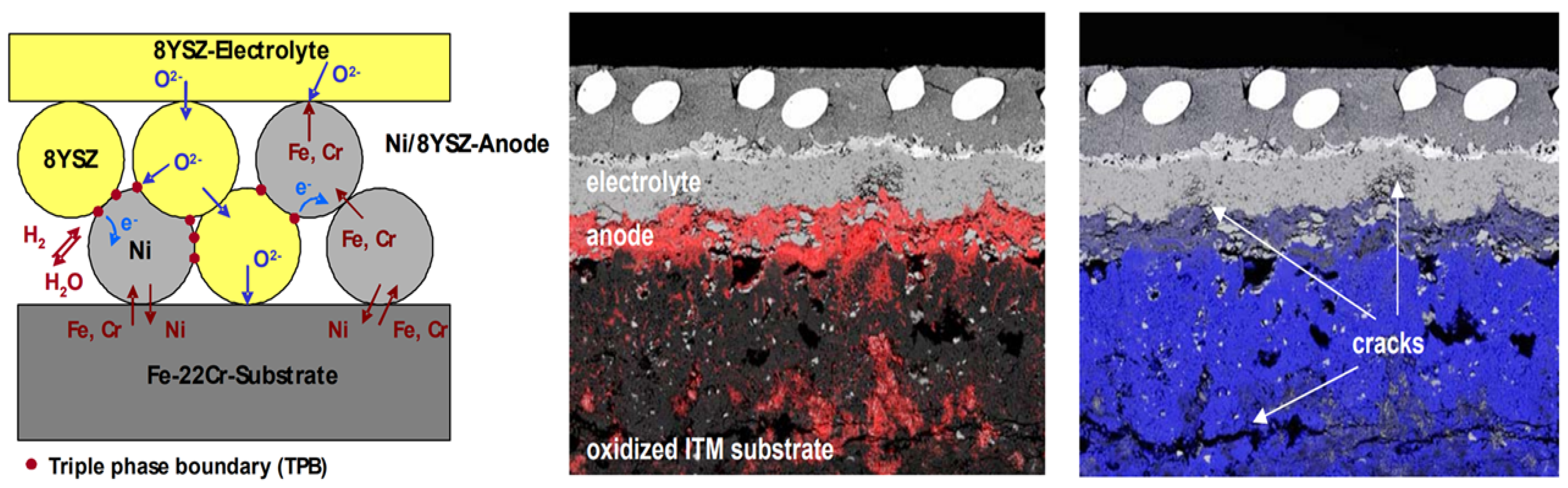
3.2. Fe-Based Metal Substrate

Ni is an excellent cathode material, and its shortcomings of a high TEC and sintering characteristics have been solved through research using various heterogeneous elements. However, owing to its high cost, many researchers are conducting research on inexpensive Fe-based metal supports. Stainless steel, which is corrosion-resistant and has a high melting point (more than 1600 K), was used as the Fe-based metal substrate material. In addition, the metal alloys exhibit TECs (1.03–1.28 × 10⁻⁵/K) well matched with that of the electrolyte. Stainless steel has different names depending on the contents of the alloy elements and additives.
In the initial study, a metal support was created using a stainless steel powder with a high Cr content (30% Cr, Ameteck, Berwyn, PA, USA), and MS-SOFC manufacturing research was conducted [88]. Stainless steel powder was manufactured into a disk by powder metallurgy, and a Ni-YSZ cathode layer and YSZ electrolyte were manufactured by tape casting using an alloy disk as a substrate. The MS-SOFC exhibited a power generation characteristic of 200 mW/cm2 at 1173 K and was stable during 50 thermal cycling tests from 473 to 1273 K at a rapid temperature change rate of 50 K/min. However, because a high Cr ratio increases the formation of a brittle sigma phase [89], many studies have used stainless steels with low Cr ratios. Ferritic stainless steel, which has a low TEC, has excellent formability and oxidation resistance, and is inexpensive, is mainly used in SOFC research. Ferritic stainless steel is a body-centered, cubic, ferromagnetic alloy that contains mainly iron and chromium, with a very low carbon content. SUS 430L [90,91,92,93], SUS 434L [94,95,96,97], and CroFer22APU [98,99,100,101] are the most common metal supports used in MS-SOFCs. Unlike Ni-based metal substrates that use metal oxides as raw materials, Fe-based metal substrates do not experience volume changes owing to reduction processes in a fuel atmosphere; therefore, pore formation for fuel permeability is important. Powder metallurgy [90,101], tape casting [91,92,93,94,95,96,97,100], chemical etching [99], and laser drilling [102] have been used to fabricate stainless steel metal substrates. In early MS-SOFC studies using stainless steels, research using powder metallurgy was conducted; however, Oishi et al. confirmed that stainless steel substrates manufactured using powder metallurgy did not provide sufficient fuel permeability to obtain the power generation properties of SOFCs as shown in Figure 4 [102]. Therefore, postprocesses, such as laser drilling [102] and wet jet cutting [98], have also been used to provide sufficient fuel permeability.
Ni-based substrates experience large volume changes during the sintering process. When the substrate is thin, it bends because of stress during the sintering process, whereas Fe-based substrates do not experience volume changes or deformation during sintering. Therefore, several research groups have utilized MS-SOFCs with thin metal substrates (less than 300 µm) through simple forming processes, such as tape casting and cofiring. The structure of an MS-SOFC manufactured using an Fe-based metal substrate is similar to that of a cell manufactured using a Ni-based substrate. However, Ni has catalytic properties, whereas Fe-based alloys do not; therefore, a Ni-based cermet anode must be manufactured between the metal substrate and the electrolyte layer. However, several researchers have reported the interdiffusion of cations, such as Ni from Ni-based cermet layers and Fe/Cr from Fe-based alloy substrates [101,103]. Diffusion of Ni into the Fe-based alloy substrate causes an austenite phase to form on the steel, which results in a TEC mismatch compared with the other cell components as shown in Figure 5. In addition, the diffusion of Fe and Cr into the cermet anode causes the formation of oxide scales (such as Cr2O3, NiCr2O4, and FeO) on the Ni particles and forms an electrochemically inactive surface. The internal diffusion of Cr from Cr-containing metal substrate occurs by vapor deposition mechanism and/or solid-state diffusion during the cell fabrication process and cell operation. Garcia-Fresnillo et al. reported that interdiffusion between an iron-based metal support and Ni in the cathode results in rapid diffusion of iron and Ni, followed by internal diffusion of Cr, and that Cr enrichment occurs at the interface due to the rate of metal ion diffusion [103]. In addition, they exhibited the results indicating that the internal diffusion of metal cations is controlled by temperature, atmosphere (especially humidity), and Cr content in Fe-based metal substrate. Franco et al. suggested the diffusion paths of cations, such as Fe, Ni, and Cr, which can generally occur during cell operation in an MS-SOFC using standard 8YSZ/Ni anodes and ferritic Fe-Cr substrate materials [104]. The formation of inactive surfaces on Ni particles and the formation of an austenite phase on the steel causes power generation to degrade rapidly (20%/1000 h). However, an MS-SOFC using a diffusion barrier layer (La0.6Sr0.2Ca0.2CrO3), which is located between the Ni-cermet and the alloy substrate, has stable power generation with a degradation rate of less than 1%. Brandner et al. studied the interdiffusion barrier effect of cations using a Cr2O3/Cr2MnO4 bilayer, Ce0.8Gd0.2O2, and CeO2. The Cr2O3/Cr2MnO4 interlayer exhibited slight effect on the prevention of Cr interdiffusion between Ni and CroFer22APU substrate. Authors have explained the insufficient performance of the interlayer related to the high amount of Cr3+ ion in the Cr2O3/Cr2MnO4, which is reduced to CrO and diffuses to the Ni layer. On the other hand, the ceria-based interdiffusion barrier was effective in blocking the internal diffusion of cations, and significant diffusion of cations was not observed, even after operation at 1073 K for 165 h [101].
In addition to research on diffusion prevention layers, research has also been conducted using ceramic anode materials instead of Ni to prevent the interdiffusion of cations. Dayaghi et al. fabricated an MS-SOFC with a La0.2Sr0.8Ti0.9Ni0.1O3−δ (LSTN)-YSZ composite anode instead of a Ni-cermet anode [95]. The MS-SOFC using a ceramic composite anode exhibited excellent stability for 40 h at 923 K, but the peak power density of 176 mW/cm2 was lower, even for a cell using an electrolyte as thin as 5 µm, than those of other MS-SOFCs using thicker electrolytes. The lower power generation property may originate from the low porosity of the composite anode (less than 15%), and so the cell structure should be investigated when using ceramic anodes in MS-SOFCs. In addition, Kim et al. confirmed that a 50 µm thick Y0.08Sr0.88TiO3-CeO2 diffusion barrier layer not only prevents cation interdiffusion but also helps maintain the electrochemical performance of the cell [94]. Interdiffusion of cations also occurred between the Fe-based alloy substrate and the proton-conducting electrolyte [105]. Wang et al. investigated the reaction between porous Fe-based alloy substrate and the most widely used proton-conducting materials, such as BZCY721 (BaZr0.7Ce0.2Y0.1O3-δ), BZCYYb4411 (BaZr0.4Ce0.4Y0.1Yb0.1O3-δ), and BZCYYb1711 (BaZr0.1Ce0.7Y0.1Yb0.1O3-δ). As a result of cation (Cr and Si) diffusion from the metal substrate, inactive BaSi2O4 and BaCrO4 formed, blocking the proton transport pathway in the electrolyte.
Because of the oxidation stability of the Fe-based alloy substrate and a TEC similar to those of other SOFC components, MS-SOFCs using Fe-based substrates are easy to manufacture in large-area cells and stacks. Ansar et al. fabricated 100 cm2 cells using Fe-based alloy substrates fabricated through powder metallurgy [106]. Their 12.56 cm2 cell exhibited a power density of 609 mW/cm2 and service life of 2000 h with a degradation rate of 1%/kh and withstood 20 redox cycles with a 2.5% degradation in power density. In addition, they succeeded in scaling up to 85 and 100 cm2 effective area cells, and the cells exhibited a power density of 400 mW/cm2. In a follow-up study, they demonstrated 10-cell stacks providing 250 W of total power with a power density of more than 300 mW/cm2 at 1073 K. Metal-supported cells are also being utilized for solid oxide electrolysis by utilizing the redox stability of Fe-based alloy substrates. Chen et al. fabricated a porous 430 L substrate using a tape-casting method and fabricated a porous scaffold and an electrode using an impregnation technique and a 15 µm thick Zr0.88Sc0.22Ce0.01O2.12 (SSZ) electrolyte. They conducted a steam electrolysis study using a cell fabricated in this manner [107]. The cell exhibited excellent reversibility in fuel cell and electrolysis modes. Wang et al. prepared an MS-SOFC with a symmetric structure on a porous stainless steel substrate [108]. Pr6O11-SDC, which has excellent catalytic properties for the oxygen evolution reaction, was used in the oxygen electrode to improve electrolysis and fuel cell performances.

4. Conclusions

SOFCs are regarded as an alternative energy conversion system because of their fast electrochemical kinetics, fuel flexibility, and high efficiency. However, their high operating temperatures and low physical strengths are issues that must be resolved. To solve these problems, many studies have been conducted on the adoption of new materials and development of third-generation SOFCs using metal substrates. Remarkable progress has been made in the study of active materials, metal substrates, and functional materials, as summarized below.
  • Research has been conducted to improve the ionic conductivity of electrolyte materials (e.g., triple-doped Bi2O3 oxygen ion conductors and doped BaZr(Ce,Y)O3 proton-conducting materials) by doping with multi-heterogeneous elements, helping lower the operating temperature of SOFCs by increasing the ion conductivity of the electrolyte, even at low temperatures.
  • To maintain and enhance the catalytic properties of Ni-based anodes and prevent reactions with electrolytes (especially LSGM electrolytes), various ceramic-based anode catalysts have been studied, and layered perovskite anode materials have shown the best catalytic properties among ceramic anode materials.
  • The low oxygen reduction reaction at low temperatures has a significant impact on the degradation of SOFC performance. Therefore, many researchers have investigated cathode materials, and various transition metals are being used. Cobalt-based materials have received attention because they provide mixed conductivity and a higher oxygen vacancy concentration than other cathode materials at low temperatures. However, the high TEC and reduced stability resulting from the sintering characteristics are issues that need to be resolved. Recently, Ruddlesden–Popper structures and layered perovskite structured cathode materials without Co have been studied extensively, and they have shown excellent mixed conductivity and stability.
  • The development of Ni-based metal substrates using heterogeneous elements helps obtain TEC values similar to those of conventional electrolytes, thereby reducing thermal stress and improving structural stability during high-temperature operation. It also helps improve the catalytic properties and pore formation, contributing to improved SOFC performance. In addition, the introduction of a functional layer (between the electrolyte and metal substrate) to suppress reactivity with electrolyte materials and increase the reaction area leads to excellent power generation characteristics, even at low temperatures. Fe-based metal substrates have TECs similar to those of electrolyte materials and have been used in many studies to manufacture MS-SOFCs; however, there are difficulties in forming sufficient pores to increase fuel utilization. In batch manufacturing processes, such as tape casting, the use of pore-forming agents to secure pores and the introduction of a side reaction barrier layer by cation diffusion have improved performance and stability, and large-area cell and stack research is being conducted.
As described in this paper, various materials have been investigated to achieve desirable power generation property of SOFC and lower the operation temperature. However, further research and development is still necessary. Especially, enhancement of catalytic activity at lower temperature and durability for long operation life is necessary for achieving a higher power generation property of SOFCs at lower temperature. Development of large-area cell manufacturing technology using thin-film electrolytes and studies on chemical and physical miscibility between SOFC components should be conducted.

Funding

This research was supported by Wonkwang University in 2024.

Conflicts of Interest

The author declares no conflict of interest.

References

  1. Dyer, C.K. Replacing the battery in portable electronics. Sci. Am. 1999, 281, 88–93. [Google Scholar] [CrossRef]
  2. Song, C. Fuel processing for low-temperature and high-temperature fuel cells: Challenges, and opportunities for sustainable development in the 21st century. Catal. Today 2002, 77, 17–49. [Google Scholar] [CrossRef]
  3. Stambouli, A.B.; Traversa, E. Solid oxide fuel cells (SOFCs): A review of an environmentally clean and efficient source of energy. Renew. Sustain. Energy Rev. 2002, 6, 433–455. [Google Scholar] [CrossRef]
  4. Minh, N.Q. Ceramic fuel cells. J. Am. Ceram. Soc. 1993, 76, 563–588. [Google Scholar] [CrossRef]
  5. Shi, H.; Su, C.; Ran, R.; Cao, J.; Shao, Z. Electrolyte materials for intermediate-temperature solid oxide fuel cells. Prog. Nat. Sci. Mater. Int. 2020, 30, 764–774. [Google Scholar] [CrossRef]
  6. Tsai, T.; Perry, E.; Barnett, S. Low-temperature solid-oxide fuel cells utilizing thin bilayer electrolytes. J. Electrochem. Soc. 1997, 144, L130–L132. [Google Scholar] [CrossRef]
  7. Kim, J.W.; Virkar, A.V.; Fung, K.Z.; Mehta, K.; Singhal, S.C. Low Temperature High Performance Anode Supported Solid Oxide Fuel Cells. J. Electrochem. Soc. 1999, 146, 69–78. [Google Scholar] [CrossRef]
  8. Ishihara, T.; Shimose, K.; Kudo, T.; Nishiguchi, H.; Akbay, T.; Takita, Y. Preparation of Yttria-Stabilized Zirconia Thin Films on Strontium-Doped LaMnO3 Cathode Substrates via Electrophoretic Deposition for Solid Oxide Fuel Cells. J. Am. Ceram. Soc. 2000, 83, 1921–1927. [Google Scholar] [CrossRef]
  9. Kim, S.D.; Hyun, S.H.; Moon, J.; Kim, J.-H.; Song, R.H. Fabrication and characterization of anode-supported electrolyte thin films for intermediate temperature solid oxide fuel cells. J. Power Sources 2005, 139, 67–72. [Google Scholar] [CrossRef]
  10. Ishihara, T.; Matsuda, H.; Takita, Y. Doped LaGaO3 perovskite type oxide as a new oxide ionic conductor. J. Am. Chem. Soc. 1994, 116, 3801–3803. [Google Scholar] [CrossRef]
  11. Ishihara, T.; Matsuda, H.; Takita, Y. Takita Effects of rare earth cations doped for La site on the oxide ionic conductivity of LaGaO3-based perovskite type oxide. Solid State Ion. 1995, 79, 147–151. [Google Scholar] [CrossRef]
  12. Badwal, S.P.S.; Fini, D.; Ciacchi, F.T.; Munnings, C.; Kimpton, J.A.; Drennan, J. Structural and microstructural stability of ceria—Gadolinia electrolyte exposed to reducing environments of high temperature fuel cells. J. Mater. Chem. A 2013, 1, 10768–10782. [Google Scholar] [CrossRef]
  13. Yu, H.; Jeong, I.; Jang, S.; Kim, D.; Im, H.N.; Lee, C.W.; Wachsman, E.D.; Lee, K.T. Temperature reduction of solid oxide electrochemical cells using triple-doped bismuth oxide. Adv. Mater. 2024, 36, 2470040. [Google Scholar] [CrossRef]
  14. Takahashi, T.; Iwahara, H.; Nagai, Y. High oxide ion conductivity of sintered Bi2O3 containing SrO, CaO or La2O3. J. Appl. Electrochem. 1972, 2, 97–104. [Google Scholar] [CrossRef]
  15. Ni, M.; Shao, Z. Fuel cells that operate at 300 ° to 500 °C. Science 2020, 369, 138–139. [Google Scholar] [CrossRef]
  16. Takahashi, T.; Iwahara, H. Solid-state ionics: Protonic conduction in perovskite type oxide solid solutions. Rev. Chim. Miner. 1980, 17, 243–253. [Google Scholar]
  17. Iwahara, H.; Esaka, T.; Uchida, H.; Maeda, N. Proton conduction in sintered oxides and its application to steam electrolysis for hydrogen production. Solid State Ion. 1981, 3–4, 359–363. [Google Scholar] [CrossRef]
  18. Iwahara, H.; Esaka, T.; Uchida, H.; Yamauchi, T.; Ogaki, K. High temperature type protonic conductor based on SrCeO3 and its application to the extraction of hydrogen gas. Solid State Ion. 1986, 18–19, 1003–1007. [Google Scholar] [CrossRef]
  19. Gao, J.; Meng, Y.; Duffy, J.H.; Brinkman, K.S. Low-Temperature Protonic Ceramic Fuel Cells through Interfacial Engineering of Nanocrystalline BaCe0.7Zr0.1Y0.1Yb0.1O3−δ Electrolytes. Adv. Energ. Sust. Res. 2021, 2, 2100098. [Google Scholar] [CrossRef]
  20. Hu, D.; Kim, J.; Niu, H.; Daniels, L.M.; Manning, T.D.; Chen, R.; Liu, B.; Feetham, R.; Claridge, J.B.; Rosseinsky, M.J. High-performance protonic ceramic fuel cell cathode using protophilic mixed ion and electron conducting material. J. Mater. Chem. A 2022, 10, 2559–2566. [Google Scholar] [CrossRef]
  21. Kreuer, K.; Adams, S.; Münch, W.; Fuchs, A.; Klock, U.; Maier, J. Maier; Proton conducting alkaline earth zirconates and titanates for high drain electrochemical applications. Solid State Ion. 2001, 145, 295–306. [Google Scholar] [CrossRef]
  22. Zvonareva, I.; Fu, X.-Z.; Medvedev, D.; Shao, Z. Electrochemistry and energy conversion features of protonic ceramic cells with mixed ionic-electronic electrolytes. Energ. Environ. Sci. 2022, 15, 439–465. [Google Scholar] [CrossRef]
  23. Duan, C.; Tong, J.; Shang, M.; Nikodemski, S.; Sanders, M.; Ricote, S.; Almansoori, A.; O’Hayre, R. Readily processed protonic ceramic fuel cells with high performance at low temperatures. Science 2015, 349, 1321–1326. [Google Scholar] [CrossRef] [PubMed]
  24. Ryu, J.; Noh, T.; Kim, J.; Lee, H. Structural change and electrical conductivity according to Sr content in Cu-doped LSM (La1-xSrxMn0.8Cu0.2O3). J. Korean Cryst. Growth C 2012, 22, 78–83. [Google Scholar] [CrossRef]
  25. Yamamoto, O.; Takeda, Y.; Kanno, R.; Noda, M. Perovskite-type oxides as oxygen electrodes for high temperature oxide fuel cells. Solid State Ion. 1987, 22, 241–246. [Google Scholar] [CrossRef]
  26. Teraoka, Y.; Zhang, H.M.; Okamoto, K.; Yamazoe, N. Mixed Ionic-Electronic Conductivity of Lal−xSrxCol−yFey03−δ Perovskite-type Oxides. Mater. Res. Bull. 1988, 23, 51–58. [Google Scholar] [CrossRef]
  27. Tai, L.W.; Nasrallah, M.M.; Anderson, H.U.; Sparlin, D.M.; Sehlin, S.R. Structure and electrical properties of La1−xSrxCo1−yFeY03. Part 1. The system La0.8Sr0.2Co1-yFey03. Solid State Ion. 1995, 76, 259–271. [Google Scholar] [CrossRef]
  28. Skinner, S.J. Recent advances in Perovskite-type materials for solid oxide fuel cell cathodes. Int. J. Inorg. Mater. 2001, 3, 113–121. [Google Scholar] [CrossRef]
  29. Shao, Z.; Haile, S.M.; Ahn, J.; Ronney, P.D.; Zhan, Z.; Barnett, S.A. A thermally self-sustained micro solid-oxide fuel-cell stack with high power density. Nature 2005, 435, 795–798. [Google Scholar] [CrossRef]
  30. Tietz, F.; Arulraj, I.; Zahid, M.; Stover, D. Electrical conductivity and thermal expansion of La0.8Sr0.2(Mn,Fe,Co)O3−δ perovskites. Solid State Ion. 2006, 177, 1753–1756. [Google Scholar] [CrossRef]
  31. Tian, Y.; Liu, Y.; Jia, L.; Naden, A.; Chen, J.; Chi, B.; Pu, J.; Irvine, J.T.; Li, J. A novel electrode with multifunction and regeneration for highly efficient and stable symmetrical solid oxide cell. J. Power Source 2020, 475, 228620. [Google Scholar] [CrossRef]
  32. Beznosikov, B.V.; Aleksandrov, K.S. Perovskite-like crystals of the Ruddlesden-Popper series. Crystallogr. Rep. 2000, 45, 792–798. [Google Scholar] [CrossRef]
  33. Torres-Garibay, C.; Kovar, D. Perovskite-related intergrowth cathode materials with thin YSZ electrolytes for intermediate temperature solid oxide fuel cells. J. Power Sources 2009, 192, 396–399. [Google Scholar] [CrossRef]
  34. Amow, G.; Davidson, I.; Skinner, S. A comparative study of the Ruddlesden-Popper series, Lan+1NinO3n+1 (n = 1, 2 and 3), for solid-oxide fuel-cell cathode applications. Solid State Ion. 2006, 177, 1205–1210. [Google Scholar] [CrossRef]
  35. Chaianansutcharit, S.; Hosoi, K.; Hyodo, J.; Ju, Y.-W.; Ishihara, T. Ruddlesden Popper oxides of LnSr3Fe3O10−δ(Ln = La, Pr, Nd, Sm, Eu, and Gd) as active cathodes for low temperature solid oxide fuel cells. J. Mater. Chem. A 2015, 3, 12357–12366. [Google Scholar] [CrossRef]
  36. Hyodo, J.; Tominaga, K.; Ju, Y.-W.; Ida, S.; Ishihara, T. Electrical conductivity and oxygen diffusivity in Cu- and Ga-doped Pr2NiO4. Solid State Ion. 2014, 256, 5–10. [Google Scholar] [CrossRef]
  37. Kim, G.; Wang, S.; Jacobson, A.J.; Reimus, L.; Brodersen, P.; Mims, C.A. Rapid oxygen ion diffusion and surface exchange kinetics in PrBaCo2O5+x with a perovskite related structure and ordered A cations. J. Mater. Chem. 2007, 17, 2500–2505. [Google Scholar] [CrossRef]
  38. Choi, S.; Yoo, S.; Kim, J.; Park, S.; Jun, A.; Sengodan, S.; Kim, J.; Shin, J.; Jeong, H.Y.; Choi, Y.; et al. Highly efficient and robust cathode materials for low-temperature solid oxide fuel cells: PrBa0.5Sr0.5Co2−xFexO5+δ. Sci. Rep. 2013, 3, 2426–2431. [Google Scholar] [CrossRef]
  39. Lee, W.; Han, J.W.; Chen, Y.; Cai, Z.; Yildiz, B. Cation Size Mismatch and Charge Interactions Drive Dopant Segregation at the Surfaces of Manganite Perovskites. J. Am. Chem. Soc. 2013, 135, 7909–7925. [Google Scholar] [CrossRef]
  40. Yoo, S.; Jun, A.; Ju, Y.; Odkhuu, D.; Hyodo, J.; Jeong, H.Y.; Park, N.; Shin, J.; Ishihara, T.; Kim, G. Development of Double-Perovskite Compounds as Cathode Materials for Low-Temperature Solid Oxide Fuel Cells. Angew. Chem. 2014, 126, 13280–13283. [Google Scholar] [CrossRef]
  41. Sun, C.; Hui, R.; Roller, J. Cathode materials for solid oxide fuel cells: A review. J. Solid State Electr. 2010, 14, 1125–1144. [Google Scholar] [CrossRef]
  42. Li, G.; Gou, Y.; Cheng, X.; Bai, Z.; Ren, R.; Xu, C.; Qiao, J.; Sun, W.; Wang, Z.; Sun, K. Enhanced Electrochemical Performance of the Fe-Based Layered Perovskite Oxygen Electrode for Reversible Solid Oxide Cells. ACS Appl. Mater. Interfaces 2021, 13, 34282–34291. [Google Scholar] [CrossRef]
  43. Zhou, Q.J.; Shi, Y.; Wei, T.; Li, Z.P.; An, D.M.; Hu, J.W.; Zhao, W.H.; Zhang, W.; Ji, Z.H.; Wang, J.H. Novel YBaCo3.2Ga0.8O7+δ as a cathode material and performance optimization for IT-SOFCs. Int. J. Hydrogen Energy 2014, 39, 10710–10717. [Google Scholar] [CrossRef]
  44. Ye, F.M.; Zhou, Q.J.; Xu, K.; Zhang, Z.Y.; Han, X.; Yang, L.; Xu, J.; Xu, H.Y.; Wu, K.J.; Guan, Y.J. Phase stability and electrochemical performance of Y0.5Ca0.5−xInxBaCo3.2Ga0.8O7+δ (x = 0 and 0.1) as cathodes for intermediate temperature solid oxide fuel cells. J. Alloys Compd. 2016, 680, 163–168. [Google Scholar] [CrossRef]
  45. Zhou, Q.; Wang, Y.; Yang, X.; Bu, F.; Yang, F.; Wang, M.; Li, Y. Basic properties of low thermal expansion coefficient (Y0.5Ca0.5)1−xInxBaCo3ZnO7+δ (x = 0, 0.1, 0.2, 0.3) solid solutions for solid oxide fuel cell cathode materials. Mater. Res. Bull. 2022, 156, 112001–112007. [Google Scholar] [CrossRef]
  46. Zhou, Q.; Zhang, X.; Wang, Y.; Ma, Y.; Yang, H. A thermal-expansion offset to cobalt-based cathode materials for solid oxide fuel cells. Next Energy 2024, 5, 100168. [Google Scholar] [CrossRef]
  47. Goodenough, J.B.; Huang, Y.-H. Alternative anode materials for solid oxide fuel cells. J. Power Source 2007, 173, 1151–1160. [Google Scholar] [CrossRef]
  48. Mogensen, M.; Skaarup, S. Kinetic and geometric aspects of solid oxide fuel cell electrodes. Solid State Ion. 1996, 86–88, 1151–1160. [Google Scholar] [CrossRef]
  49. Iwanschitz, B.; Sfeir, J.; Mai, A.; SchütZe, M. Degradation of SOFC anodes upon redox cycling: A comparison between Ni/YSZ and Ni/CGO. J. Electrochem. Soc. 2010, 157, B269–B278. [Google Scholar] [CrossRef]
  50. Liu, M.; Lynch, M.E.; Blinn, K.; Alamgir, F.M.; Choi, Y. Rational SOFC material design: New advances and tools. Mater. Today 2011, 14, 534–546. [Google Scholar] [CrossRef]
  51. Slater, P.R.; Fagg, D.P.; Irvine, J.T.S. Synthesis and electrical characterisation of doped perovskite titanates as potential anode materials for solid oxide fuel cells. J. Mater. Chem. 1997, 7, 2495–2498. [Google Scholar] [CrossRef]
  52. Sengodan, S.; Yeo, H.J.; Shin, J.; Kim, G. Assessment of perovskite-type La0.8Sr0.2ScxMn1−xO3−δ oxides as an anode for intermediate temperature solid oxide fuel cells using hydrocarbon. J. Power Sources 2011, 196, 3083–3088. [Google Scholar] [CrossRef]
  53. Corre, G.; Kim, G.; Cassidy, M.; Vohs, J.M.; Gorte, R.J.; Irvine, J.T.S. Activation and ripening of impregnated manganese containing perovskite SOFC electrodes under redox cycling. Chem. Mater. 2009, 21, 1077–1084. [Google Scholar] [CrossRef]
  54. Tao, S.; Irvine, J.T.S. A redox-stable efficient anode for solid-oxide fuel cells. Nat. Mater. 2003, 2, 320–323. [Google Scholar] [CrossRef]
  55. Shin, T.H.; Ida, S.; Ishihara, T. Doped CeO2–LaFeO3 composite oxide as an active anode for direct hydrocarbon-type solid oxide fuel cells. J. Am. Chem. Soc. 2011, 48, 19399–19407. [Google Scholar] [CrossRef]
  56. Peng, X.; Tian, Y.; Liu, Y.; Wang, W.; Jia, L.; Pu, J.; Chi, B.; Li, J. An efficient symmetrical solid oxide electrolysis cell with LSFM-based electrodes for direct electrolysis of pure CO2. J. CO2 Util. 2020, 36, 18–24. [Google Scholar] [CrossRef]
  57. Yang, C.; Yang, Z.; Jin, C.; Xiao, G.; Chen, F.; Han, M. Sulfur-tolerant redox-reversible anode material for direct hydrocarbon solid oxide fuel cells. Adv. Mater. 2012, 24, 1439–1443. [Google Scholar] [CrossRef] [PubMed]
  58. Huang, Y.-H.; Dass, R.I.; Xing, Z.-L.; Goodenough, J.B. Double perovskites as anode materials for solid-oxide fuel cells. Science 2006, 312, 254–257. [Google Scholar] [CrossRef]
  59. Zhang, L.; Zhou, Q.; He, Q.; He, T. Double-perovskites A2FeMoO6−δ (A = Ca, Ba) as anodes for solid oxide fuel cells. J. Power Sources 2010, 195, 6356–6366. [Google Scholar] [CrossRef]
  60. Sengodan, S.; Choi, S.; Jun, A.; Shin, T.H.; Ju, Y.-W.; Jeong, H.Y.; Shin, J.; Irvine, J.T.S.; Kim, G. Layered oxygen-deficient double perovskite as an efficient and stable anode for direct hydrocarbon solid oxide fuel cells. Nat. Mater. 2015, 14, 205–209. [Google Scholar] [CrossRef]
  61. Sengodan, S.; Ju, Y.-W.; Kwon, O.; Jun, A.; Jeong, H.Y.; Ishihara, T.; Shin, J.; Kim, G. Self-Decorated MnO Nanoparticles on Double Perovskite Solid Oxide Fuel Cell Anode by in Situ Exsolution. ACS Sustain. Chem. Eng. 2017, 5, 9207–9213. [Google Scholar] [CrossRef]
  62. Williams, K.R.; Smith, J.G. Fuel Cell with Solid State Electrolytes. US3 1969, 464, 861. [Google Scholar]
  63. Okuo, T.; Kaga, Y.; Momma, A. New Tubular Type SOFC Using Metallic System Components. Denkikagaku 1996, 64, 555–561. [Google Scholar] [CrossRef]
  64. Momma, A.; Kaga, Y.; Fujii, K.; Hohjyo, K.; Kanazawa, M.; Okuo, T. High Potential Performance of Tubular Type SOFC using Metallic System Components. Proc. Electrochem. Soc. 1997, 1997, 311–320. [Google Scholar] [CrossRef]
  65. Mineshige, A.; Inaba, M.; Ogumi, Z.; Takahashi, T.; Kawagoe, T.; Tasaka, A.; Kikuchi, K. Preparation of Yttria-Stabilized Zirconia Microtube by Electrochemical Vapor Deposition. J. Am. Ceram. Soc. 1995, 78, 3157–3159. [Google Scholar] [CrossRef]
  66. Mineshige, A.; Fukushima, K.; Okada, S.; Kikuchi, T.; Kobune, M.; Yazawa, T.; Kikuchi, K.; Inaba, M.; Ogumi, Z. Porous metal tubular support for solid oxide fuel cell design. Electrochem. Solid-State Lett. 2006, 9, A427–A429. [Google Scholar] [CrossRef]
  67. Hwang, C.; Tsai, C.-H.; Lo, C.-H.; Sun, C.-H. Plasma sprayed metal supported YSZ/Ni–LSGM–LSCF ITSOFC with nanostructured anode. J. Power Sources 2008, 180, 132–142. [Google Scholar] [CrossRef]
  68. Hwang, C.-S.; Tsai, C.-H.; Yu, J.-F.; Chang, C.-L.; Lin, J.-M.; Shiu, Y.-H.; Cheng, S.-W. High performance metal-supported intermediate temperature solid oxide fuel cells fabricated by atmospheric plasma spraying. J. Power Sources 2011, 196, 1932–1939. [Google Scholar] [CrossRef]
  69. Cho, H.J.; Choi, G.M. Fabrication and characterization of Ni-supported solid oxide fuel cell. Solid State Ion. 2009, 180, 792–795. [Google Scholar] [CrossRef]
  70. Ishihara, T.; Yan, J.; Shinagawa, M.; Matsumoto, H. Ni–Fe bimetallic anode as an active anode for intermediate temperature SOFC using LaGaO3 based electrolyte film. Electrochim. Acta 2006, 52, 1645–1650. [Google Scholar] [CrossRef]
  71. Ju, Y.-W.; Eto, H.; Inagaki, T.; Ida, S.; Ishihara, T. Preparation of Ni–Fe bimetallic porous anode support for solid oxide fuel cells using LaGaO3 based electrolyte film with high power density. J. Power Sources 2010, 195, 6294–6300. [Google Scholar] [CrossRef]
  72. Ishihara, T.; Kusaba, H.; Kim, H.H.; Kang, B.S. Preparation of La0.9Sr0.1Ga0.8Mg0.2O3 Film by Pulse Laser Deposition (PLD) Method on Porous Ni–Fe Metal Substrate for CO2 Electrolysis. ISIJ Int. 2019, 59, 613–618. [Google Scholar] [CrossRef]
  73. Ju, Y.-W.; Eto, H.; Inagaki, T.; Ida, S.; Ishihara, T. Improvement in Thermal Cycling Durability of SOFCs Using LaGaO3-Based Electrolyte by Inserting Convex Sm0.5Sr0.5CoO3 Interlayer. Electrochem. Solid-State Lett. 2010, 13, B139–B141. [Google Scholar] [CrossRef]
  74. Ju, Y.-W.; Ida, S.; Ishihara, T. A Ce(Mn,Fe)O2 dense nanofilm as an improved active anode for metal-supported solid oxide fuel cells. RSC Adv. 2013, 3, 10508–10515. [Google Scholar] [CrossRef]
  75. Ju, Y.; Hyodo, J.; Inoishi, A.; Ida, S.; Tohei, T.; So, Y.; Ikuhara, Y.; Ishihara, T. Double columnar structure with a nanogradient composite for increased oxygen diffusivity and reduction activity. Adv. Energy Mater. 2014, 4, 1400783. [Google Scholar] [CrossRef]
  76. Li, K.; Wang, X.; Jia, L.; Yan, D.; Pu, J.; Chi, B.; Jian, L. High performance Ni–Fe alloy supported SOFCs fabricated by low cost tape casting-screen printing-cofiring process. Int. J. Hydrogen Energy 2014, 39, 19747–19752. [Google Scholar] [CrossRef]
  77. Park, H.C.; Virkar, A.V. Bimetallic (Ni–Fe) anode-supported solid oxide fuel cells with gadolinia-doped ceria electrolyte. J. Power Sources 2009, 186, 133–137. [Google Scholar] [CrossRef]
  78. Lee, Y.; Choi, G.M. Ceria Film Supported on Ni-Fe Metal Film. ECS Trans. 2009, 25, 727–730. [Google Scholar] [CrossRef]
  79. Wang, M.; Li, N.; Wang, Z.; Chen, C.; Zhan, Z. Electrochemical performance and redox stability of solid oxide fuel cells supported on dual-layered anodes of Ni-YSZ cermet and Ni–Fe alloy. Int. J. Hydrogen Energy 2022, 47, 5453–5461. [Google Scholar] [CrossRef]
  80. Kim, H.Y.; Watanabe, M.; Song, J.T.; Inada, M.; Ishihara, T. BaZr(Ce,Y)O3-Pr-Doped CeO2 Double Columnar for the Cathodic Functional Layer of Ni–Fe Metal-Supported Protonic Ceramic Fuel Cells. ACS Appl. Energy Mater. 2024, 7, 7945–7955. [Google Scholar] [CrossRef]
  81. Kim, H.Y.; Watanabe, M.; Song, J.T.; Inada, M.; Ishihara, T. A high power metal-supported protonic ceramic fuel cell using increased proton conductivity in the cathode functional layer of La1−xSrxScO3 (LSSc, x = 0.1–0.25). J. Mater. Chem. A 2025, 13, 1172–1180. [Google Scholar] [CrossRef]
  82. Vafaeenezhad, S.; Sandhu, N.K.; Hanifi, A.R.; Etsell, T.H.; Sarkar, P. Development of proton conducting fuel cells using nickel metal support. J. Power Sources 2019, 435, 226763. [Google Scholar] [CrossRef]
  83. Wang, R.; Lau, G.Y.; Ding, D.; Zhu, T.; Tucker, M.C. Approaches for co-sintering metal-supported proton-conducting solid oxide cells with Ba(Zr,Ce,Y,Yb)O3−δ electrolyte. Int. J. Hydrogen Energy 2019, 44, 13768–13776. [Google Scholar] [CrossRef]
  84. Babar, Z.U.; Hanif, M.B.; Gao, J.T.; Li, C.J.; Li, C.X. Sintering behavior of BaCe0.7Zr0.1Y0.2O3−δ electrolyte at 1150 °C with the utilization of CuO and Bi2O3 as sintering aids and its electrical performance. Int. J. Hydrogen Energy 2022, 47, 7403–7414. [Google Scholar] [CrossRef]
  85. Sadykov, V.A.; Usoltsev, V.V.; Fedorova, Y.E.; Sobyanin, V.A.; Kalinin, P.V.; Arzhannikov, A.V.; Vlasov, A.Y.; Korobeinikov, M.V.; Bryazgin, A.A.; Salanov, A.N.; et al. Design of medium–temperature solid oxide fuel cells on porous supports of deformation strengthened Ni–Al alloy. Russ. J. Electrochem. 2011, 47, 488–493. [Google Scholar] [CrossRef]
  86. Yang, S.-F.; Hwang, C.-S.; Tsai, C.-H.; Chang, C.-L.; Wu, M.-H.; Fu, C.-Y.; Lee, R.-Y. Fabrication of 100 Centimeter Square Metal-Supported Solid Oxide Fuel Cell Using Thermal Plasma Technique. ECS Trans. 2017, 78, 2021–2028. [Google Scholar] [CrossRef]
  87. Tsai, C.H.; Hwang, C.S.; Chang, C.L.; Wu, S.H.; Lin, H.H.; Shiu, W.H.; Lin, J.K.; Yang, S.F.; Fu, C.Y.; Yang, C.S. Performances of Plasma Sprayed Metal-supported Solid Oxide Fuel Cell and Stack. Fuel Cells 2018, 18, 680–823. [Google Scholar] [CrossRef]
  88. Villarreal, I.; Jacobson, C.; Leming, A.; Matus, Y.; Visco, S.; De Jonghe, L. Metal-Supported Solid Oxide Fuel Cells. Electrochem. Solid-State Lett. 2003, 6, A178–A179. [Google Scholar] [CrossRef]
  89. Wang, Y.; Sun, H.; Li, N.; Xiong, Y.; Jing, H. Effect of Sigma Phase Precipitation on the Pitting Corrosion Mechanism of Duplex Stainless Steels. Int. J. Electrochem. Sci. 2018, 13, 9868–9887. [Google Scholar]
  90. Xie, Y.; Neagu, R.; Hsu, C.-S.; Zhang, X.; Decès-Petit, C. Spray pyrolysis deposition of electrolyte and anode for metal-supported solid oxide fuel cell. J. Electrochem. Soc. 2008, 155, B407–B410. [Google Scholar] [CrossRef]
  91. Zhan, Z.; Zhou, Y.; Wang, S.; Liu, X.; Meng, X.; Wen, T. Nanostructure electrodes for metal-supported solid oxide fuel cells. ECS Trans. 2013, 57, 925–931. [Google Scholar] [CrossRef]
  92. Zhou, Y.; Xin, X.; Li, J.; Ye, X.; Xia, C.; Wang, S.; Zhan, Z. Performance and degradation of metal-supported solid oxide fuel cells with impregnated electrodes. Int. J. Hydrogen Energy 2014, 39, 2279–2285. [Google Scholar] [CrossRef]
  93. Zhou, Y.; Han, D.; Yuan, C.; Liu, M.; Chen, T.; Wang, S.; Zhan, Z. Infiltrated SmBa0.5Sr0.5Co2O5+δ cathodes for metal–supported solid oxide fuel cells. Electrochim. Acta 2014, 149, 231–236. [Google Scholar] [CrossRef]
  94. Kim, K.J.; Kim, S.J.; Choi, G.M. Y0.08Sr0.88TiO3-CeO2 Composite as a Diffusion Barrier Layer of STS-Supported SOFC. ECS Trans. 2013, 57, 897–903. [Google Scholar] [CrossRef]
  95. Dayaghi, A.M.; Kim, K.J.; Kim, S.; Park, J.; Kim, S.J.; Park, B.H.; Choi, G.M. Stainless steel-supported solid oxide fuel cell with La0.2Sr0.8Ti0.9Ni0.1O3-δ/yttria-stabilized zirconia composite anode. J. Power Sources 2016, 324, 288–293. [Google Scholar] [CrossRef]
  96. Dogdibegovic, E.; Cheng, Y.; Shen, F.; Wang, R.; Hu, B.; Tucker, M.C. Scaleup and manufacturability of symmetric-structured metal-supported solid oxide fuel cells. J. Power Sources 2021, 489, 229439. [Google Scholar] [CrossRef]
  97. Hu, B.; Lau, G.; Song, D.; Fukuyama, Y.; Tucker, M.C. Optimization of metal-supported solid oxide fuel cells with a focus on mass transport. J. Power Sources 2023, 555, 232402. [Google Scholar] [CrossRef]
  98. Jang, Y.-H.; Lee, S.; Shin, H.Y.; Bae, J. Development and evaluation of a 3-cell stack of metal-based solid oxide fuel cells fabricated via a sinter-joining method for auxiliary power unit applications. Int. J. Hydrogen Energy 2018, 43, 16215–16229. [Google Scholar] [CrossRef]
  99. Lee, K.; Kang, J.; Lee, J.; Lee, S.; Bae, J. Evaluation of metal-supported solid oxide fuel cells (MS-SOFCs) fabricated at low temperature (~1000 °C) using wet chemical coating processes and a catalyst wet impregnation method. Int. J. Hydrogen Energy 2018, 43, 3786–3796. [Google Scholar] [CrossRef]
  100. Fernández-González, R.; Hernández, E.; Savvin, S.; Núñez, P.; Makradi, A.; Sabaté, N.; Esquivel, J.; Ruiz-Morales, J. A novel microstructured metal-supported solid oxide fuel cell. J. Power Sources 2014, 272, 233–238. [Google Scholar] [CrossRef]
  101. Brandner, M.; Bram, M.; Froitzheim, J.; Buchkremer, H.; Stöver, D. Electrically Conductive Diffusion barrier layers for Metal-Supported SOFC. Solid State Ion. 2008, 179, 1501–1504. [Google Scholar] [CrossRef]
  102. Oishi, N.; Yoo, Y. Fabrication of Cerium Oxide Based SOFC Having a Porous Stainless Steel Support. ECS Trans. 2009, 25, 739–744. [Google Scholar] [CrossRef]
  103. Franco, T.; Schibinger, K.; Ilhan, Z.; Schiller, G.; Venskutonis, A. Ceramic Diffusion Barrier Layers for Metal Supported SOFCs. ECS Trans. 2007, 7, 771–780. [Google Scholar] [CrossRef]
  104. Garcia-Fresnillo, L.; Shemet, V.; Chyrkin, A.; de Haart, L.; Quadakkers, W. Long-term behaviour of solid oxide fuel cell interconnect materials in contact with Ni-mesh during exposure in simulated anode gas at 700 and 800 °C. J. Power Sources 2014, 271, 213–222. [Google Scholar] [CrossRef]
  105. Szabo, P.; Arnold, J.; Franco, T.; Gindrat, M.; Refke, A.; Zagst, A.; Ansar, A. Progress in the Metal Supported Solid Oxide Fuel Cells and Stacks for APU. ECS Trans. 2009, 25, 175–185. [Google Scholar] [CrossRef]
  106. Ansar, A.; Szabo, P.; Arnold, J.; Ilhan, Z.; Soysal, D.; Costa, R.; Zagst, A.; Gindrat, M.; Franco, T. Metal Supported Solid Oxide Fuel Cells and Stacks for Auxiliary Power Units—Progress, Challenges and Lessons Learned. ECS Trans. 2011, 35, 147–155. [Google Scholar] [CrossRef]
  107. Chen, T.; Zhou, Y.; Liu, M.; Yuan, C.; Ye, X.; Zhan, Z.; Wang, S. High performance solid oxide electrolysis cell with impregnated electrodes. Electrochem. Commun. 2015, 54, 23–27. [Google Scholar] [CrossRef]
  108. Wang, R.; Dogdibegovic, E.; Lau, G.Y.; Tucker, M.C. Metal-Supported Solid Oxide Electrolysis Cell with Significantly Enhanced Catalysis. Energy Technol. 2019, 7, 1801154. [Google Scholar] [CrossRef]
Figure 1. Electrical conductivity of the SOFC electrolyte materials: doped ZrO2 (YSZ, ScSZ), doped CeO2 (SDC, GDC) fluorite oxides; LaGaO3-based (LSGM) and widely studied Ba-based cerates (BCY), zirconates (BZY), and their solid solutions (BCZY, BZCYYb) perovskites. Reproduced with permission of Elsevier [5].
Energies 18 03379 g001
Figure 2. Arrhenius plots of the current density at the anodic overpotential of 30 mV on various Ni-based bimetallic anodes. The values in the figure are the estimated activation energies (eV). Reproduced with permission of Elsevier [69].
Energies 18 03379 g002
Figure 4. Electrochemical properties of a metal-supported solid oxide fuel cell (MS-SOFC) using metal substrate fabricated by powder metallurgy and laser drilling. (a) I–V curves at 873 K and (b) Impedance plots of cells having different porous supports under open circuit voltage. Reproduced with permission of IOP Publishing [102].
Energies 18 03379 g004
Figure 5. Diffusion tracks for Fe, Ni, and Cr on the anode side in MS-SOFCs at cell operation (left) and EDX maps of element distribution in the measured MS-SOFC for 1500 h (red: Ni distribution; blue: Fe distribution). Reproduced with permission of IOP Publishing [103].
Energies 18 03379 g005
Disclaimer/Publisher’s Note: The statements, opinions and data contained in all publications are solely those of the individual author(s) and contributor(s) and not of MDPI and/or the editor(s). MDPI and/or the editor(s) disclaim responsibility for any injury to people or property resulting from any ideas, methods, instructions or products referred to in the content.

