Article

Effect of Different Heat Sink Designs on Thermoelectric Generator System Performance in a Turbocharged Tractor

1
Department of Mechanical, Istanbul Gelisim University, Istanbul 34310, Türkiye
2
Department of Mechanical Engineering, Pamukkale University, Denizli 20160, Türkiye
*
Author to whom correspondence should be addressed.
Energies 2025, 18(13), 3267; https://doi.org/10.3390/en18133267
Submission received: 8 May 2025 / Revised: 5 June 2025 / Accepted: 19 June 2025 / Published: 22 June 2025

Abstract

In this study, the effects of different heat sink designs on the cold side of the modules in a thermoelectric generator (TEG) system placed between the compressor and the intercooler of a turbocharged tractor on the system performance were numerically analyzed. In the current literature, heat sinks used in TEG modules generally consist of plate fins. In this study, by using perforated and slotted fins, the thermal boundary layer behaviors were changed and there was an attempt to increase the heat transfer from the cold surface compared to plate fins. Thus, the performance of the TEG system was also increased. When looking at the literature, it is seen that there are studies which aim to increase the performance of TEG modules by changing the dimensions of p and n type semiconductors. However, there is no study aiming to increase the performance of TEG modules by making changes on the plate fins of the heat sinks used in these modules and thus increasing the heat transfer amount. In this respect, this study offers important results for the literature. According to the numerical analysis results, the total TEG output power, output voltage, and thermal efficiency obtained for S0.5H15 were 6.2%, about 3%, and about 5% higher than those for PF, respectively. In addition, the pressure drop values obtained for different heat sinks, except for aluminum foam, were approximately close to each other. In cases with TEG systems where different heat sinks were used, the intercooler inlet air temperatures decreased by approximately 3.4–3.5% compared to the case without the TEG system. This indicates that the use of TEG will positively affect the improvement in engine efficiency.

1. Introduction

Thermoelectric systems are widely used today as both thermoelectric generators (TEGs) and thermoelectric coolers (TECs). TEGs can also generate electrical energy using waste heat such as exhaust gas. When looking at the literature, it is seen that exhaust gases with high temperatures and therefore high thermal energy are generally used to obtain electrical energy with TEG in internal combustion engines. Wolf et al. [1] analyzed the power output and conversion efficiency of thermoelectric (TE) modules using different geometric optimization strategies. Bi2Te3, semi-Heusler, and oxide-based modules were characterized by FEM simulations, and the optimum performance differences depending on different materials were investigated. He et al. [2] investigated the effect of thermal energy recovery from engine exhaust gases with TEG systems on the temperature gradient. Their work has provided important findings in determining structural dimensions for optimal performance under different exhaust conditions using commercial TE materials. In their experimental studies, Sofyan et al. [3] examined the effect of different layouts of the heat recovery system and aluminum fin arrangements on the production of electrical energy from the exhaust gas temperature through thermoelectric modules (TEMs). In the experiments, the results obtained by operating the motor at different rotation speeds (1300, 1600, 1900 and 2200 RPM) indicated that the highest current and voltage were produced by all blade arrangements at 2200 RPM (122 mA and 12.52 V, respectively). Kober et al. [4] verified the performance of systems equipped with a thermoelectric module (TEM) with simulations by working on a functional prototype developed with a holistic optimization method. The prototype passed successful tests on the hot gas test bench and the simulation results and measurement data were shown to be compatible. Karana and Sahoo [5] evaluated the performance for a twisted fin exhaust heat exchanger of a diesel engine at six different operating points. Their studies have revealed that certain combinations of geometric parameters of twisted tape provide the highest electrical power and have the potential for better fuel efficiency than alternative flat-surface systems. Karana and Sahoo [6] performed the energy and exergy analysis for a TE waste heat recovery system of an automobile using an aluminum-based heat exchanger. Their work determined the TE performance and the optimum thickness for the heat exchanger through experiments with load changes under constant engine speed. Kumar et al. [7] investigated the conversion of waste heat into electrical energy by TEGs. The TEG module connected with the internal combustion engine exhaust heat exchanger obtained the output voltage and power by maintaining the temperature difference between the hot and cold surfaces between 10 °C and 80 °C. Liao et al. [8] examined optimum designs in a TE system powered by vehicle exhaust. In their study, they evaluated the effects of electric current on electrical power and energy conversion efficiency by solving the thermal balance equations of TEMs using irreversible heat transfer theory. Corar et al. [9] studied the effects of different TEM connections on thermal efficiency and electrical power for automotive TEGs (ATEG). In their study, parallel, square and serial connections were examined at two different motor running points and they found that the square connection provided the optimal balance between the electrical power, current and voltage of the TEGs. Zhou et al. [10] examined the effect of module placement on the electrical power in the automotive exhaust TE power generation system. Their studies demonstrated the changes in module spacing and coverage ratio on output power under different operating conditions and revealed that large-sized modules can increase power output by improving temperature uniformity. Nonthakarn et al. [11] stated that the maximum electrical output obtained by the turbo generator and TEG they developed for diesel engines was 1262 W at 3400 rpm and 0.1024 kg/s. This study demonstrates the effectiveness of a potential technology for electricity generation using vehicle exhaust gas. Kalteh and Garmejani [12] analyzed the effect of Thomson heat on the electrical output and thermal efficiency for the TEG. In their research, they determined that the Thomson effect of Pb-Te alloy has a positive effect for electrical output and thermal efficiency at temperatures above 650 K. Subramaniam et al. [13] developed a special test rig to evaluate the performance of automotive exhaust TEGs. The study reveals that the overall efficiency for the TEG is only 0.4% due to the low efficiency of the finned structure of the hot side. Al-Nimr and Alajlouni [14] examined electricity production by using the high temperature difference of a TEM placed on the wall of the firebox of an engine. As a result of their research, they determined that their system could produce 600 W electrical energy at 4000 rpm with 2.75% higher efficiency. In Temizer’s [15] study, the TEG prototype developed by utilizing the exhaust heat of a diesel engine produced 156.7 W maximum electrical power through serially connected aluminum 6061 structure TEMs. The prototype was simulated in detail with heat–flow analyses and thermal–electrical analyses performed with Ansys Workbench and Fluent programs. Gürcan and Yakar [16] reported their work with TEG modules on an octagonal pipe located between the intercooler and compressor in a tractor. The study evaluated the power output of TEGs at different outdoor temperatures and stated that the highest performance occurred at 268 K. Gürcan and Yakar [17] examined the electrical output of a TEG system located between the intercooler and compressor in a tractor. The study revealed that the electric current generated by various TEMs augmented with an increase in the module’s cross-sectional area, and these modules positively influenced tractor performance.
Studies in the literature contribute to the development of finned structure designs and the determination of optimum heat sinks used in various applications. There are also studies aimed at increasing heat transfer with heat sinks. Sahin and Demir [18] reported that the use of circular cross-section perforated pin fins in rectangular channels increases heat transfer and causes a pressure drop. In the study conducted with the Taguchi experimental design method, results were obtained in which parameters such as Reynolds number, wing height and inter-wing distance were determined for optimum performance. Sahin and Demir [19] examined the effect of square-section perforated pin fins on a rectangular section channel. In the experiments carried out in this channel, they studied heat transfer and friction factor under different Reynolds numbers and void ratios. With the Taguchi experimental design method, they reached results that recommended a low clearance ratio, a low inter-blade clearance ratio and relatively low Reynolds numbers for optimum performance. Dhanawade et al. [20] compared the heat transfer of rectangular fin arrays with square and circular holes on a horizontal flat surface in forced convection. The study concluded that square holes are superior to circular holes. Al Sallami et al. [21] computationally studied the advantages of the cross-sectional aspect ratio between plate fins and pin fins of strip fin heat sinks (SFHSs). Their studies have shown that strip fin arrangements have the potential to increase heat transfer, especially in staggered arrangements, and that perforated strip fins provide a significant benefit in reducing processor temperatures in microelectronic cooling applications. Al-Damok et al. [22] computationally studied the advantages of using pin heat sinks (PHSs) with single, rectangular slotted or notched pin perforations. Their study showed that the heat transfer increased while the pressure drop decreased with increasing size of rectangular holes, and they compared the favorable heat transfer and pressure drop characteristics of PHSs with multiple circular holes. Chang et al. [23] examined the free convective flow and heat transfer of vertical fin arrays with or without dimples in their numerical study. The results showed that dimpled fin arrays showed higher heat transfer performance than flat fin arrays, and this difference became especially evident as the Rayleigh number increased. Haghighi et al. [24] experimentally examined the thermal performance of plate fins and plate cubic pin-fin heat sinks under natural convection conditions. Their studies have shown that plate cubic pin fin heat sinks have lower thermal resistance and provide between 10% and 41.6% higher heat transfer compared to regular pin fins. Kim and Kim [25] experimentally examined the effect of cross cuts on the thermal performance of heat sinks under parallel flow. Their research found that cross-cut length and location can significantly improve the thermal performance of heat sinks, and that cross-cut heat sinks are superior to other design types. Gupta et al. [26] experimentally examined the heat transfer and flow performance of a plate-finned heat sink with pits and protrusions in a horizontal rectangular channel. The study revealed that varying the dimple depth and spacing has significant effects on the heat transfer of the fin array. Khudhur et al. [27] examined the heat transfer performance of straight parallel finned heat sinks using different fin types using experimental and computational methods. The study revealed that especially flat plate-additional fin and flat plate-subtractive fin heat sinks show better thermal performance than other fin types at high Reynolds numbers and turbulent forced convection conditions. Liu et al. [28] investigated heat transfer and flow behavior for a regenerative cooling channel with pin fins using supercritical CO2 as coolant. They found that the cooling channel with pin fins obtained a heat transfer improvement of 3.08, a friction factor of 4.66, thermal performance improvement of 1.84, and the maximum temperature of the hot surface was decreased by 36% for Re = 45,000 according to a smooth cooling channel. Liu et al. [29] studied heat transfer and flow behavior for regenerative cooling channels utilizing supercritical CO2 as coolant with circular tetrahedral lattice structures. When the channel material was copper, the overall thermal performance was 3.24 times higher than that of steel.
In TEGs, an increase in the temperature difference between the hot and cold surfaces causes an increase in voltage. Plate fin heat sinks are traditionally used in TEGs, and using these heat sinks in TEGs can provide significant improvements in electrical power generation and thus the thermal efficiency of TEGs. In addition, studies have shown that factors such as heat sink design, flow rate and thermal resistance have great effects on TEG performance. T’Jollyn et al. [30] made a model to determine how well TEGs work in plate fin heat sinks that have forced convection on the cold side. This model evaluates the effects of thermal resistance, electrical load, and design parameters on the power output and efficiency of the TEG. Rezania and Rosendahl [31] discovered that the net power output of TEGs depends on the configuration of the heat sinks. They found that plate fin heat sinks produce high net power output at low flow rates, while cross-cut heat sinks produce higher net power output at high flow rates. Barma et al. [32] said that the design of the plate fin heat sink and the flow parameters have big impacts on the electricity production in TEGs that are built into industrial thermal oil heaters and put between the flue gas and fresh air ducts. Wiriyasart and Naphon [33] studied how heat dissipation is affected in cold plate heat sinks with different fin shapes using the jet impingement technique and found that circular fins provide 12% to 25% lower thermal resistance compared to rectangular and tapered fins. Barma et al. [34] stated that equipping TEG modules placed in industrial thermal oil heaters with plate fin heat sinks optimizes power production and increases the thermal efficiency of the system by up to 7%. Xu et al. [35] conducted an investigation into the structural optimization of the heat sink in TE conversion units used in personal comfort systems. They found that improving the design of the heat sink is an effective way to make the TE conversion unit more efficient at exchanging heat, and these methods have a big impact on the design of personal comfort systems. Pujol et al. [36] stated that the model they developed was validated by experimental data and was effective in determining the optimum design of the heat sink to provide the maximum net electric power of TEGs. Specifically, they observed that fin thickness changes were less effective than fin spacing changes. Pouryoussefi and Zang [37] investigated the forced convection cooling performance of air-cooled parallel plate fin heat sinks with and without circular pins between the plate fins. They stated that increasing the air velocity increased the heat sink efficiency but also increased the pressure drop, and that the pin heat sink offered 37.7% lower thermal resistance compared to the original design.
Recently, new technologies such as low-temperature phase change materials (PCMs) and metal foam have been used to increase energy efficiency and improve thermal management. Rezania et al. [38] aimed to develop a more efficient system by integrating a low-temperature phase change material (PCM) and shielded copper foam to eliminate the cooling energy requirement in TEGs. The results show that the proposed system is 53.5% more efficient than traditional fan-driven TEGs and provides an effective cooling solution. Li et al. [39] proposed a thermal energy management system with the combination of a foam/PCM composite and a TEG for passive cooling, heat storage, and electric energy harvesting. The results showed that the foam/PCM composite lowered the heat source temperature by offering high thermal conductivity but reduced the TE power generation. Wang et al. [40] proposed an open-cell metal foam-filled plate heat-exchanger-based TEG (HE-TEG) system to utilize low-grade waste heat. The experimental prototype increased the heat exchange efficiency to 83.56%, and the TE power generation performance was improved by various improvement methods. Yousefi et al. [41] aimed to improve thermal management by using a phase change material (PCM) and copper foam to stabilize temperature fluctuations and prevent overheating in TEG systems. The results show that the combination of the PCM and foam makes the system safer and more efficient while also increasing energy production by allowing heat to spread more quickly.
In turbocharged systems, heat exchangers are used before or after the intercooler to ensure cooler air enters the engine and thus increase engine efficiency. Kaul et al. [42] performed an analysis of the heated air channel between the intercooler and the turbocharger. They determined that plastics contribute to significant weight reduction and greater design flexibility compared to metal pipes. Xu et al. [43] examined the effect of different methanol injection positions on methanol/diesel dual fuel engine performance and emissions. The results of this study showed that the lowest in-cylinder pressure and the slowest heat transfer rate were determined for low-load conditions, but NOx emissions decreased the most for high-load and high-speed conditions. Tauzia et al. [44] conducted an experimental study on the combustion and emissions of water injection into the intake manifold of an automotive direct injection diesel engine. They performed a comparison with exhaust gas recirculation to estimate the potential of an inlet WI device for in-cylinder emission reduction in automotive application. Di Battista et al. [45] investigated the thermal and flow behavior of engine intake air for fuel and emission reduction. They determined that when the engine was operated in light duty type under stationary conditions and the intake air sub-cooling was turned on, the net fuel consumption was in the order of 1%.
The increase in the amount of heat given to the outdoor from the cold surface of the TEG system significantly affects the thermal efficiency of the system. This increase is provided by the heat sinks of the cold side. Therefore, this study focused on the performance improvements of heat sinks on the cold surface of TEG systems. In other words, the main purpose of this study was to determine how much the efficiency of TEGs was improved compared to plate fin heat sinks by making circular perforations and slots on the fins of traditional plate fin heat sinks used in practice and using these new-design heat sinks instead of traditional plate fin heat sinks. Therefore, in this study, a region that has never been studied before in TEGs was studied, and heat transfer was increased by opening circular perforations and slots on the plate fins of the heat sinks used in TEG modules, and thus heat sinks with newly designed fins that provide better performance of TEG modules were obtained. When considering the literature, additional processes applied to the fin surface to change the boundary layer behavior are very valuable because they provide increased heat transfer. Therefore, the ideas presented to change the boundary layer behavior are highly valued by the literature. When considering the literature, it is seen that studies are generally conducted to increase the performance of these TEGs by changing the dimensions of p and n type semiconductors. However, no study has been conducted to improve the performance of TEG modules by changing the fins of heat sinks used in these modules. In this respect, this study provides important results for the literature. In addition, when the literature is examined, the fact that the air coming out of the TEG system is colder is also important for improving engine efficiency. In addition to the main purpose of this study, it was determined that TEGs with new-design and traditional plate fin heat sinks caused a decrease in the air temperatures entering the intercooler compared to the case without TEG. Therefore, it has been realized that these results are also important in terms of engine efficiency. Additionally, no research has been found on increasing the thermal efficiency of TEG systems by changing the boundary layer behavior by using perforated and slotted plate fins instead of the traditional plate fins used in the heat sinks of TEG modules. Therefore, the use of these different heat sinks reveals the originality of this study. In this respect, the numerical results obtained provide important contributions to both the literature and practice.
Moreover, while the TEG system produces electrical power, it also provides a decrease in the temperature of the air entering the intercooler according to the conservation of energy, compared to the situation without TEG. This will contribute positively to the engine efficiency of the turbocharged tractor.

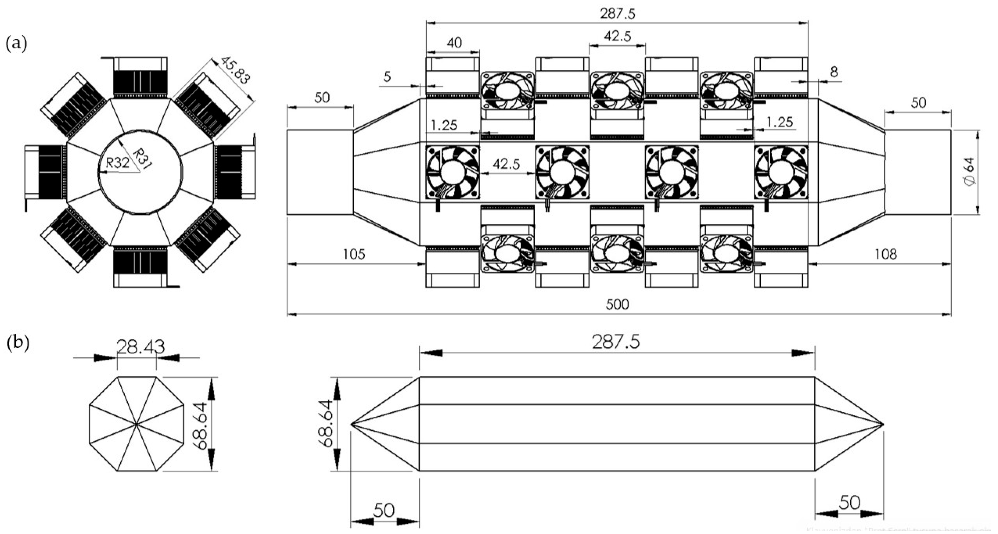
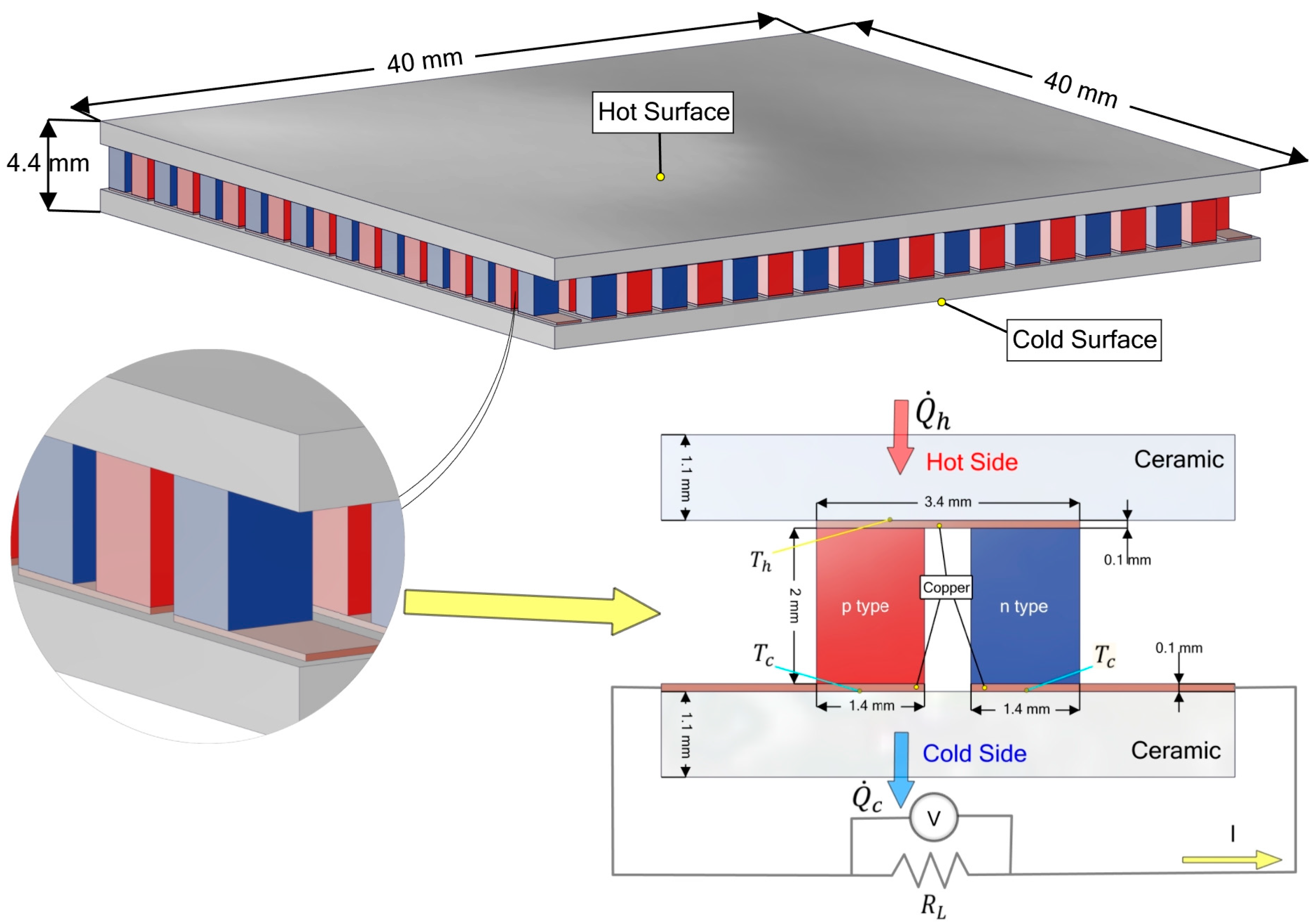
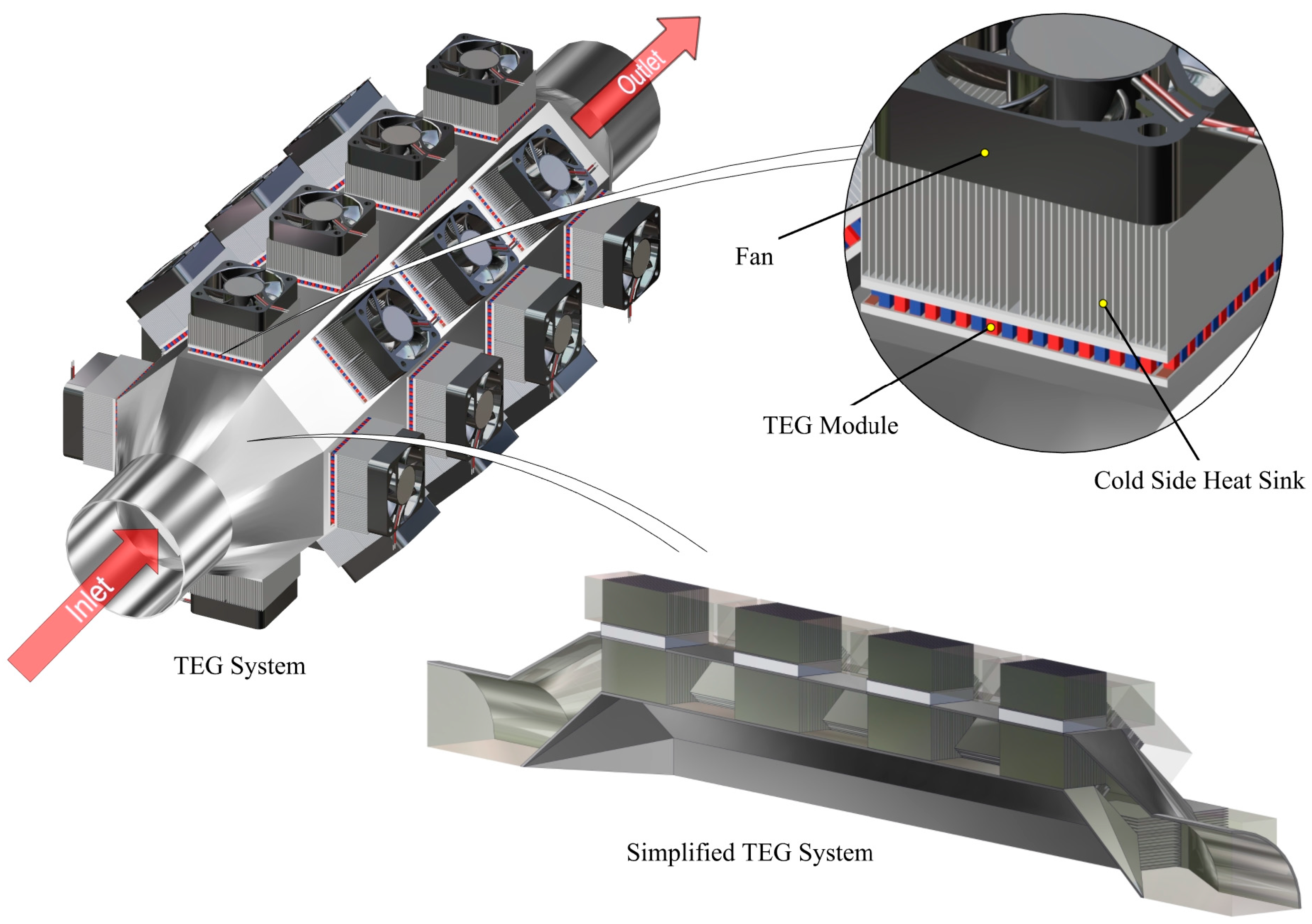
2. Structure of the TEG System of a Turbocharged Tractor and Material Properties

In the current literature, the thermal energy of exhaust gases is generally used in TEGs of automobiles. In our previous studies, unlike in the current literature, the production of electrical energy from the thermal energy of the air coming out of the compressor of a turbocharged tractor, owing to the TEG system placed between the compressor and the intercooler, was investigated numerically. In this study, in addition to this situation, heat sinks with different designs on the cold surface of the TEG module were investigated. Therefore, the effects of plate fin, aluminum foam, perforated plate fin and slotted plate fin heat sinks on TEG performance and intercooler inlet temperature were numerically determined using the Ansys-Fluent and Ansys-Thermal-Electric programs.
In this study, a total of 28 TEG modules were placed on a regular octagonal cross-section pipe with a side length of 45 mm and a cross-sectional area of 0.0098 m2 in seven rows, with four in each row [46]. The octagonal cross-section pipe design was preferred because it provides symmetrical air flow owing to its proximity to the circular structure and allows for the placement of more TEG modules due to its large surface area. Figure 1a shows the general layout of the TEG system integrated into a turbocharged tractor.
The hot surfaces of the TEG modules are positioned to come into contact with the heated air coming out of the compressor, while the fan-assisted external air flow is directed to the cold surfaces. Since electrical power generation is directly dependent on the temperature difference between the hot and cold surfaces of the module, the hot and cold air flows are modeled in opposite directions to maximize this difference (Figure 1b). As the temperature difference increases, the electrical power obtained from the modules also increases.
Placing modules in different locations in the system causes different temperature differences to occur in each module and therefore each module produces different amounts of electrical power. Due to the fully symmetrical structure between the TEG modules, the positional effects of the modules from TEG1 to TEG7, as shown in Figure 1b, were analyzed as representatives of each row. In this approach, it was assumed that the TEG module in each row would show a similar performance and the overall behavior of the system was evaluated over these representative modules.
In Figure 2a, the module layout of the TEG system is visually presented. In order to direct the hot air coming out of the compressor to the heat sink surfaces in a more homogeneous and efficient way, and thus to increase the thermal efficiency of the TEG modules, a deflector with octagonal pyramid-shaped tips, the geometric features of which are given in Figure 2b, was designed. In other words, this deflector regulates the air flow and ensures that most of the hot air at the compressor outlet passes through the TEG modules, increasing the efficiency of conversion into electrical energy. Therefore, the air will enter the intercooler at a lower temperature.
In this study, the temperature of the air entering the TEG system located at the tractor’s turbocharger compressor outlet is 135 °C, the mass flow rate is 0.162 kg/s, the pressure increase rate (Pk/Po) is 2.2, and the diameter of the outlet pipe is 64 mm [47].
The TGM199–1.4–2.0 commercial module was used in this study. The dimensions of this module are stated in the catalog as 40 mm × 40 mm × 4.4 mm (Figure 3). The expressions in the TGM199–1.4–2.0 commercial module are explained as follows: TGM represents the TEG module, 199 represents the number of p and n thermocouples in the module, 1.4 represents the edge length of a section of the p or n semiconductor, and 2.0 represents the leg length of the p or n semiconductor [48]. Figure 3 shows the schematic structure and dimensions of the TEG module used in this study.
TEG modules have been simplified to provide greater simplicity, lower computational cost, and usability in large-scale simulations by ignoring geometrical complexities. This simplification also offers the advantage of obtaining accurate results. The simplification is shown in Figure 4. With this simplification process, the equivalent thermal conductivity coefficient has been calculated.
The density and specific heat values for the TEG module were selected as the properties of the bismuth telluride material, and the thermal conductivity coefficient was calculated as the equivalent thermal conductivity coefficient since the TEG module was simplified. Equations (1) and (2) were used in this calculation [49].
R T E M = H T E M k T E M A m
where RTEM is the total thermal resistance, HTEM is the total height, kTEM is the equivalent thermal conductivity coefficient, and Am is the area of the TEM that heat passes through. The RTEM is taken as 1.39 K/W, which is the value specified in the catalog of the TGM199-1.4-2.0 TEG module [50].
A m = 2 H c e 2 H c e + 2 H c o + H l e g A c e + H c o 2 H c e + 2 H c o + H l e g N c o A c o + H l e g 2 H c e + 2 H c o + H l e g N p + N n A l e g              
where ceramic’s height is Hce, the copper conductor’s height is Hco, the p-n thermocouple leg length is Hleg, the ceramic material cross-sectional area is Ace, through which heat passes perpendicularly, the copper conductor cross-sectional area is Aco, through which heat passes perpendicularly, the p-n thermocouple cross-sectional area is Aleg, through which heat passes perpendicularly, the copper conductor number is Nco, the p type semiconductor number is Np, and the n type semiconductor number is Nn.
In the calculations, by using the geometry information of TGM199-1.4-2.0 in the Kryotherm catalog; Hce = 1.1 mm, Hco = 0.1 mm, Hleg = 2 mm, HTEM = 4.4 mm, Ace = 0.016 m2, Aco = 4.76 × 10⁻⁶ m2, Aleg = 1.96×10⁻⁶ m2, Nco = 398, Np = 199 and Nn = 199 were found. By using these values in Equation (2), Am = 0.0012 m2 was calculated. The equivalent thermal conductivity was calculated from Equation (1) as kTEM = 2.6379 W/(m∙K).
In this study, different heat sinks were used at the cold side of the TEM, as seen in Figure 5, and the effects of different heat sinks on the TEG performance and intercooler inlet air temperature were investigated. Firstly, three different heat sink designs were examined: the plate fin (PF) heat sink, the heat sink created by perforating 16 circular perforations, each with a diameter of 1 mm, into the fin bases of the PF heat sink, and the heat sink created by perforating 6 rows of 16 circular perforations, each with a diameter of 1 mm, starting from the fin bases of the PF heat sink. Secondly, three different open-cell aluminum foams with 10, 20, and 40 PPI (Pore Per Inch) values were examined. Thirdly, eight different heat sinks with different slot widths (0.5, 1, 1.5, and 2 mm) and slot heights (3 and 15 mm) starting from the fin tips of PF heat sinks were examined (Figure 5).

3. Mathematical Modeling of TEG System

3.1. TEG Equations

A steady-state heat transfer is intended for the TEGs. It is also supposed that convection and radiation on the thermocouple surfaces are negligible, that the electrical and thermal contact resistance in the TEGs is insignificant, that the TEGs are perfectly insulated, and that the thermoelements (p- and n-type) are similar. The thermoelectric properties of TEGs are constant. That is, the changes in properties with temperature have been neglected. According to these assumptions, the following ideal equations have been obtained [51].
The following equations show the energy transfer associated with both the hot and cold surfaces of the TEGs. h and c are subscripts representing the hot and cold sides, respectively. The numerical analyses of this study were made based on the following equations [51]:
The thermal energy extracted at the hot side:
Q ˙ h = n α T h I 1 2 I 2 R + K T h T c
where
α = α p + α n    
R = ρ p L p A p + ρ n L n A n            
K = k p A p L p + k n A n L n      
Since the thermoelements (p- and n- type) are similar, R = ρ L / A and K = k A / L , where ρ = ρ p + ρ n and k = k p + k n . R is the internal electrical resistance and K is the thermal conductance. In addition, L is the leg length of the semiconductor (p- and n-type), A is the cross-sectional area of the semiconductors, α is the Seebeck coefficient of the semiconductors, k is the thermal conductivity of the semiconductors and ρ is the electrical resistivity of the semiconductors [51].
Heat released to the outdoor at the cold side:
Q ˙ c = n α T c I + 1 2 I 2 R + K T h T c
The electrical current of the TEG module:
I = α T h T c R L + R
The total voltage for TEG is as follows:
V n = n I R L = n α T h T c I R = n α T h T c R L R + 1 R L R
The total power output (with an external load resistance) is as follows:
W ˙ n = n I R L = I V
and in relation to the internal properties, it is as follows:
W ˙ n = n α I T h T c I 2 R = n α 2 T h T c 2 R R L R 1 + R L R 2
The thermal efficiency is as follows:
η t h = W ˙ n Q ˙ h
When Equation (12) is rearranged using Equations (3) and (11), Equation (13) is as follows:
η t h = 1 T c T h R L R 1 R L R 1 2 1 T c T h + 1 2 Z T ¯ 1 R L R 2 1 + T c T h
in which T ¯ = T h + T c 2 and Z = α 2 / ρ k (Z: the figure of merit)
The dimensionless electrical resistance:
R r = R L R
In this study, we aimed to simulate the performance of the TEG module using the ideal Equations (3)–(13). In the modeling in question, the TE material properties of the module, namely, electrical resistivity (σ), Seebeck coefficient (α) and thermal conductivity (k), must be known. However, commercial TEG module manufacturers generally share only the maximum parameter values such as Imax, Vmax, Wmax and ηmp in their product catalogs; they do not provide detailed information about the TE material properties (α, σ and k). In addition, the fact that the ideal equations do not include various losses such as electrical and thermal contact resistance, the Thomson effect and heat losses causes deviations between the modeled results and the actual measured values. Including these losses in the equations significantly complicates the solution. This situation explains the differences between the performance curves plotted based on ideal equations and thermoelectric material properties and the performance curves measured from commercial modules. In this context, Lee [51] formulated the concept of “effective material properties” to account for losses in the TE system design. The effective material properties are described as realistic material properties obtained using maximum parameters provided by manufacturers. Therefore, in addition to the intrinsic material properties, effective material properties include thermal and electrical contact resistances, temperature dependence of thermoelectric material properties, and losses due to heat losses to the ambient environment [51]. These effective properties should be divided into two and evaluated separately since they include both p-type and n-type thermoelements. In this context, the effective electrical resistivity can be expressed as follows [51].
ρ * = 4 A / L W ˙ m a x n I m a x 2
The effective Seebeck coefficient:
α * = 4 W ˙ m a x n I m a x T h T c
The effective figure of merit:
Z * = 1 T ¯ 1 + η m a x η c T c T h 1 η m a x η c 2 1
in which η C is the Carnot cycle efficiency η C = 1 T c / T h [51].
The effective thermal conductivity:
k * = α * 2 ρ * Z *

3.2. Ansys-Fluent Theory

The shear-stress transport (SST) k ω model was developed by Menter [52] to effectively blend the robust and accurate formulation of the k ω model in the near-wall region with the free-stream independence of the k ε model in the far field. The turbulence kinetic energy, k , and the specific dissipation rate, ω , are as follows:
t ρ k + x i ρ k u i = x j Γ k k x j + G k Y k + S k + G b
t ρ ω + x i ρ ω u i = x j Γ w w x j + G w Y w + S w + G w b
where Gω and Gk are the generation of ω and k, respectively, and Γω and Γk are the effective diffusivity of ω and k, respectively. Yω and Yk are the dissipation of ω and k in the turbulence, respectively, Dω is the cross diffusion, and Sω and Sk are the source terms.
Γ k = μ + μ t σ k
Γ ω = μ + μ t σ ω
where σ k ve σ ω are the turbulence Prandtl numbers for k and ω, respectively [53]. The appropriate transport behavior is as follows:
μ t = ρ k ω 1 m a x 1 ψ *   ,   S F 2 ψ 1 ω
where S is the strain rate magnitude and the coefficient ψ * reduces the turbulent viscosity, resulting in a low Reynolds number correction. This is given in Equation (24) below. F 2 is given in Equation (26) [53].
ψ * = ψ * ψ 0 * + R e t / R k 1 + R e t / R k
where R k = 6 , ψ 0 * = β i 3 and β i = 0.072 [53]. R e t :
R e t = ρ k μ ω
In the high Reynolds number form of the k ω model, ψ * = ψ * = 1 [53].
F 2 = tanh Φ 2 2
where Φ 2 :
Φ 2 = max 2 k 0.09 ω y   ,   500 μ ρ y 2 ω
where y represents the distance to the next surface [53].
The constants of the SST k ω turbulence model are σ k , 1 = 1.176 , σ w , 1 = 2.0 , σ k , 2 = 1.0 , σ w , 2 = 1.168 , ψ 1 = 0.31 , β i , 1 = 0.075 and β i , 2 = 0.0828 . All additional model constants ( ψ * , ψ , ψ 0 , β * , R β , R k , R ω , ζ * and M t 0 ) have the same values as the standard k ω turbulence model [53].

3.3. Aluminum Foam in Ansys-Fluent

Porous media are modeled by adding a momentum source term to the standard fluid flow equations. The source term Si added to the momentum equation of the porous medium is as follows: [54]
S i = j = 1 3 D i j μ v j + j = 1 3 C i j 1 2 ρ v v j
For a simple homogeneous porous medium, the Fluent’s source term is as follows:
S i = μ δ   v i + C 2 1 2 ρ v v i
where δ is the permeability and C 2 is the inertial resistance factor. D and C denote as diagonal matrices with 1/ δ and C 2 on the diagonals, respectively (zero for other elements) [54].
Ansys-Fluent solves the standard energy transport equation in porous medium regions by only modifying the conduction flux and permeation terms. In a porous medium, the conduction flux is calculated using an effective thermal conductivity, and the permeation term includes the thermal inertia of the solid region in the medium. The energy equation for porous medium is as follows [54]:
t γ ρ f E f + 1 γ ρ s E s + · v ρ f E f + p = · k e f f T i h i J i + τ ̿ · v + S f h
where E f is the total fluid energy, E s is the total solid medium energy, γ is the porosity of the medium, k e f f is the effective thermal conductivity of the medium, and S f h is the enthalpy source term of the fluid [54].
Effective thermal conductivity in porous medium:
k e f f = γ k f + 1 γ k s
where the thermal conductivity of the fluid phase is k f , and the thermal conductivity of the solid medium is k s . The anisotropic effective thermal conductivity can also be denoted with user-defined functions. In this case, the isotropic contributions from the fluid, γ k f , annexed to the diagonal elements of the solid anisotropic thermal conductivity matrix [54].

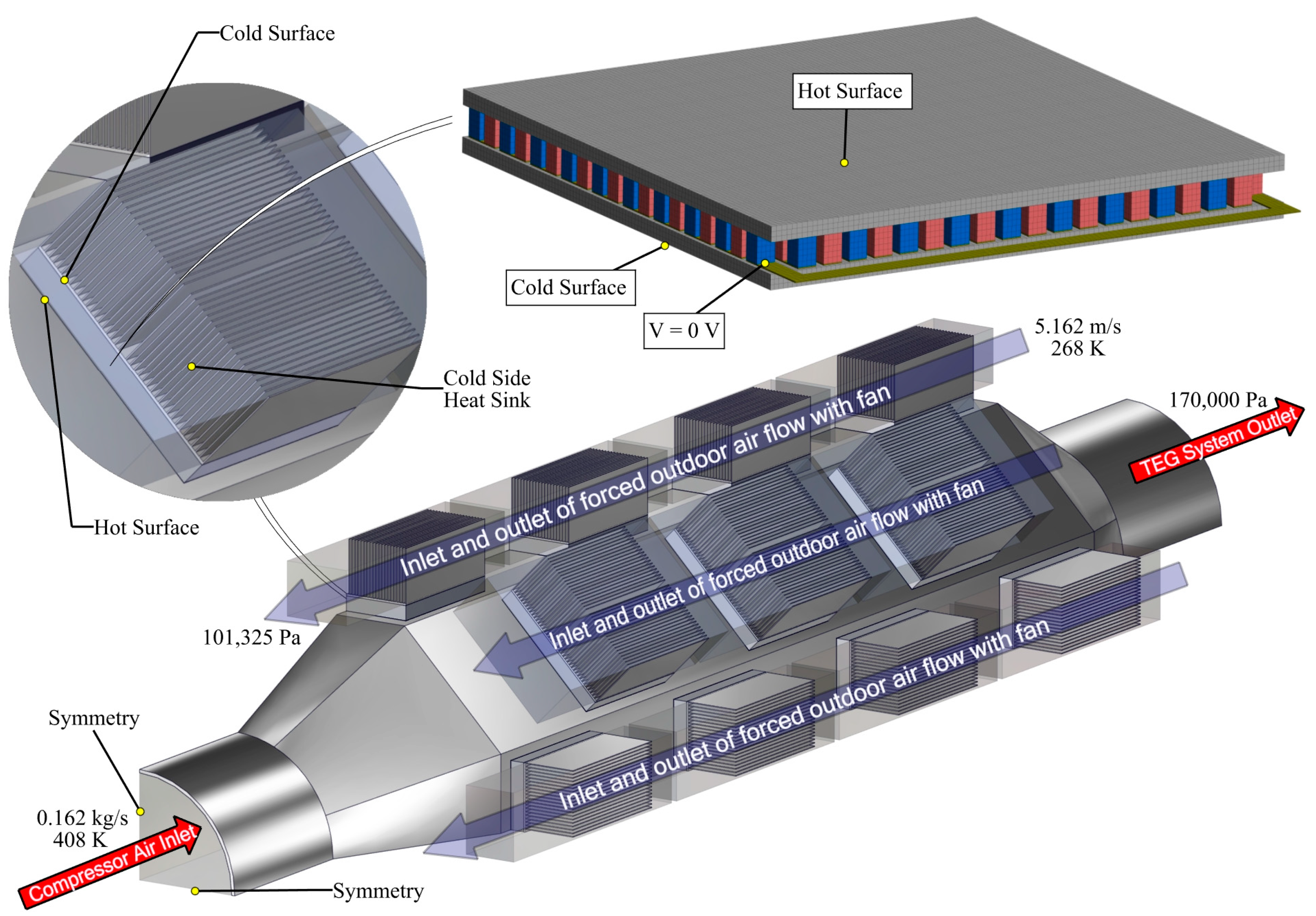
3.4. Mesh and Boundary Conditions

This study explored a TEG system that used the thermal energy of compressed air. There are two different flow areas in the TEG system. The first flow area was the air flow coming out of the compressor with a temperature of 408 K, and the second flow area was the cold air flow defined as “air at outdoor temperature”. In the study, the outdoor air temperature was assumed to be 268 K, and therefore the outdoor heat transfer coefficient for heat transfer between the air and the TEG system was found to be 22.85 W/m2K. As shown in Figure 6, the inlet boundary conditions of the air coming from the compressor were defined as 0.162 kg/s mass flow rate, 222,915 Pa (2.2 bar) absolute pressure and 408 K temperature. The outlet boundary condition was determined as the pressure outlet with an average pressure value of 170,000 Pa.
The inlet boundary conditions of the air coming from the fans were defined as 5.162 m/s air velocity and 268 K temperature. The outlet boundary condition was 101,325 Pa at the absolute pressure outlet.
In the Ansys-Fluent program, when the density of a fluid is selected as “ideal gas”, the program recommends the operating pressure (effective pressure) to be 0 Pa. Therefore, the pressure outlet of the fan air coming from the fan and leaving the heat sink was determined as 101,325 Pa absolute pressure.
One quarter of the TEG system was analyzed, and symmetry boundary conditions were applied.
The thermophysical properties of the compressor air used in the simulations are listed in Table 1. At an outdoor temperature of 268 K, the thermophysical properties of air are as follows: density 1.3165 kg/m³, heat transfer coefficient 0.02326 W/m K, specific heat 1006 J/kg K, and dynamic viscosity 1.7045 × 10⁻⁵ Pa s. The thermophysical material properties of the main components constituting the TEG system are given in Table 2. The properties of the aluminum foam material are presented in Table 3 [55].
Numerical analyses were performed using Ansys-Fluent 2024R1 and Ansys-Thermal-Electric 2024R1 software. Thermal–electrical simulation of TEG modules was performed with the hot- and cold-surface temperature data of TEG obtained from Ansys-Fluent analysis.
In the TEG system of the turbocharged tractor, the PF heat sinks were used in the octagonal sectioned pipe through which the compressor air passes. Although different types of heat sinks were used on the cold surfaces of the TEGs (see Figure 5), the heat sinks in the octagonal pipe were kept constant without being changed. In this direction, the TEG system of the turbocharged tractor was examined under the same boundary conditions in all analyses.
The heat transfer and flow model were analyzed by solving under steady-state conditions. The SST k-omega turbulence model and Coupled solver were used in the calculations, and the Hybrid Initialization method was preferred in the initialization process. Certain convergence criteria were applied to ensure the accuracy of the solution and the numerical stability. The scaled residual value for the momentum equations was kept below 10−3 and for the energy equations below 10−6. In addition, the relative error in terms of total energy conservation of the system was limited to below 0.1% and the energy balance conditions were verified.
For the Ansys-Thermal-Electric simulation, at least one thermal boundary condition, such as temperature, convection, radiation or heat flux, and at least one electrical boundary condition, such as voltage or current, must be defined. As an electrical boundary condition, 0 V electric potential was applied to the front face of the copper conductor on the side where the semiconductor n region is located (Figure 6). As a thermal boundary condition, the hot- and cold-surface temperature values of the TEG module were used. Therefore, Ansys-Thermal-Electric analyses based on the finite element method were performed using the hot- and cold-surface temperatures obtained with the Ansys-Fluent program analysis. Figure 7 illustrates the poly-hexcore mesh of the TEG system.
In Figure 8, the pressure, temperature and velocity distributions of the flow in a regular octagonal pipe are shown on stepped sections.

3.5. Grid Independence Examination

In Ansys-Fluent, the number and quality of meshes are critical in terms of the accuracy of the analysis results and the calculation time. Therefore, various mesh configurations should be tested to achieve optimum results.
Table 4 shows the mesh optimization results for 268 K. The accuracy of the optimization was evaluated with parameters such as the inlet pressure to the intercooler, the inlet temperature to the intercooler, and the mass flow rate entering the intercooler. Table 4 illustrates that grids 1 and 2 yield similar results.
In order to perform the analysis in a shorter time and reduce CPU consumption, grid 2 was used in the subsequent analyses. The appropriate mesh setting increases the reliability of the analyses and ensures an efficient use of system resources.
Table 5 presents the grid analysis for TEG1 module. The seven identified TEG modules were simulated individually using a single-module model in the Ansys-Thermal-Electric interface.

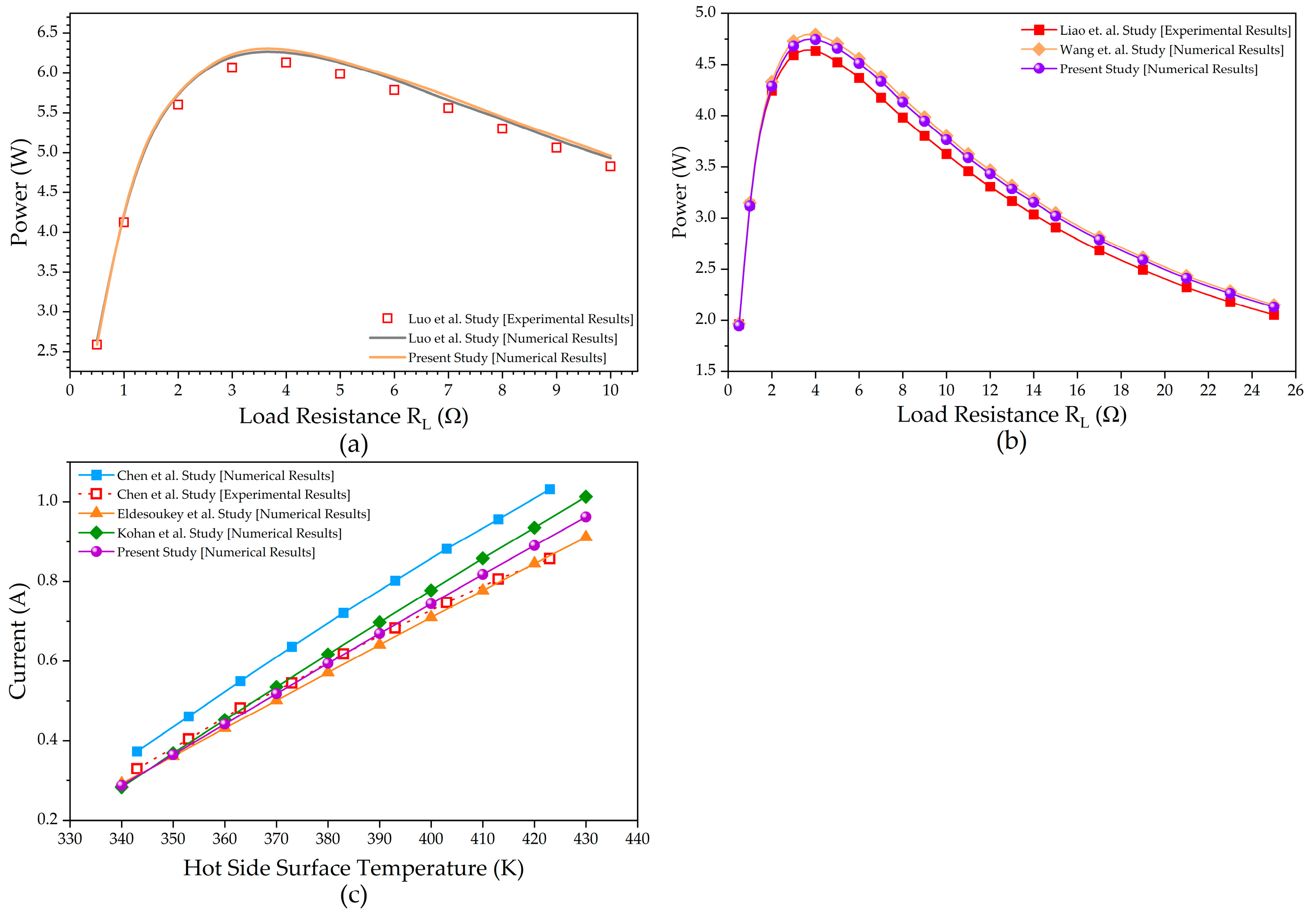
3.6. Validation of the Model

The experimental studies in Figure 9a–c were carried out by taking into account the change in thermoelectric material properties with temperature. Therefore, in order to make a comparison with the results of these experimental studies, numerical analyses were carried out in the present study by taking into account the change in thermoelectric material properties with temperature.
To demonstrate the validation of the numerical model, the physical model of the TEG system from Ref. [49] was recreated. Then, the boundary conditions and terms were put into the Ansys program, and numerical simulations were run. Figure 9a shows the Ansys simulation results, which agree closely with the experimental and numerical results in Ref. [49]. While the maximum output power error was reported as 2.18% in Ref. [49], it was determined as 2.82% in the Ansys simulation with the same model and boundary conditions. This low error rate demonstrates the numerical accuracy and reliability of the model.
In the second validation, the numerical results of Wang et al. [56] and the numerical results of the present study were compared with the experimental results of Liao et al. [57] (Figure 9b). The average relative deviation for output power reported by Wang et al. was 4.82%, while the average relative deviation for output power obtained by the present study was 3.86%. This shows that the numerical results of this study are in good agreement with the experimental results of Liao et al.
In the third validation, the models of Chen et al. [58], Eldesoukey et al. [59] and Kohan et al. [60], who studied the same TEC1-12706 thermoelectric module, were recreated using the finite element (FE) data they used. The comparison findings are illustrated in Figure 9c. The average relative error of the model of Eldesoukey et al. was 3% according to the experimental results of Chen et al. In addition, the average relative error of the model of Kohan et al. was lower than 1% at low temperatures and 8% at high temperatures. The average relative error of the model of the present study was lower than 1% in the low-temperature region and 5.5% in the high-temperature region. This shows that the model of this study provides higher accuracy compared to others (Figure 9c).

4. Results and Discussion

In this study, a TEG system was added between the compressor of the turbocharged tractor and the intercooler. The purpose of this system is to produce electrical energy. In this case, according to the conservation of energy, the air entering the intercooler is also cooled to a lower temperature. The aim of this study is to investigate new design heat sinks that can transfer more heat from the cold side of the TEG modules to the outdoor in order to increase the efficiency of the TEG system.

4.1. Numerical Results on the Performance of TEG Systems with Different Heat Sink Designs

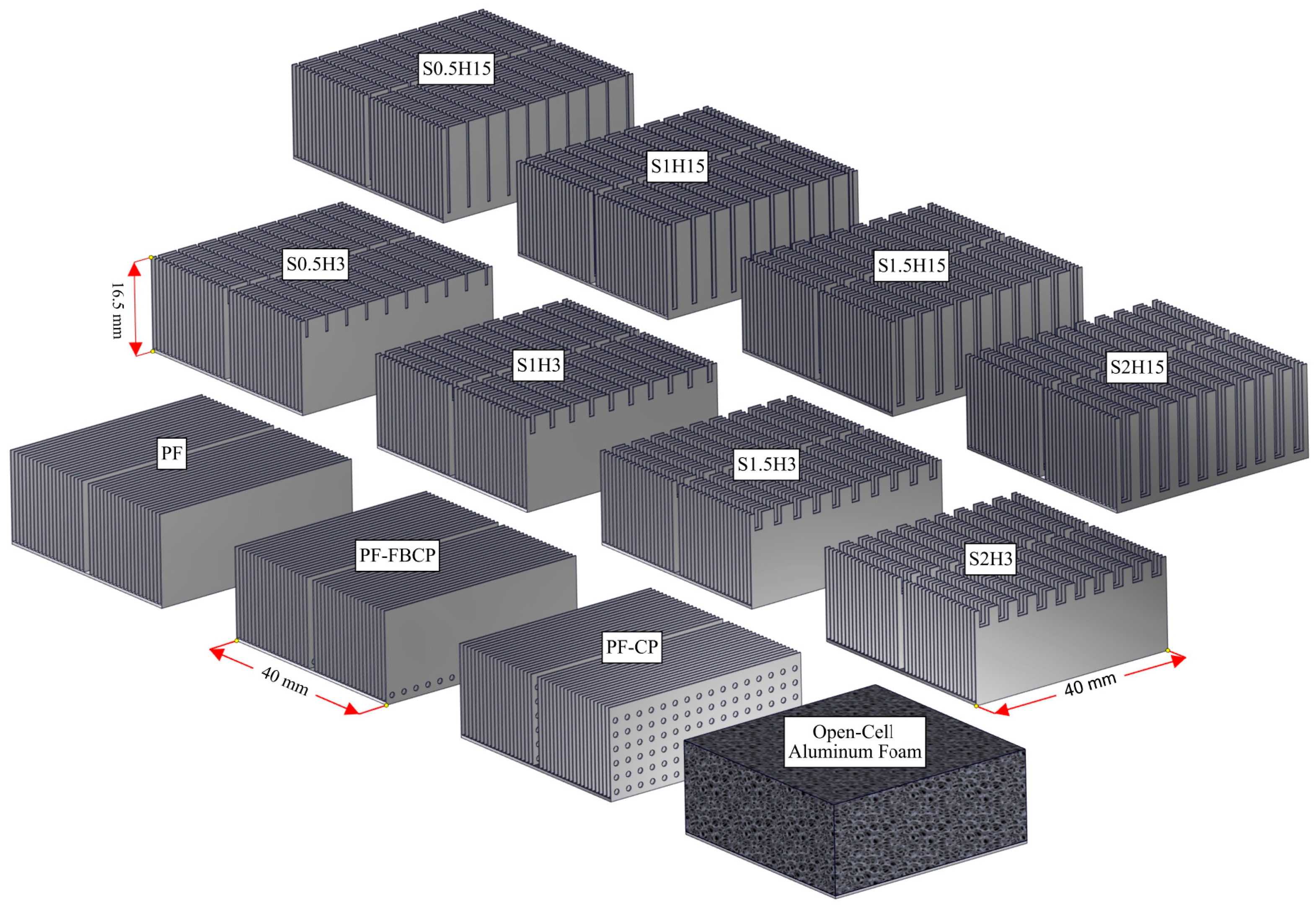
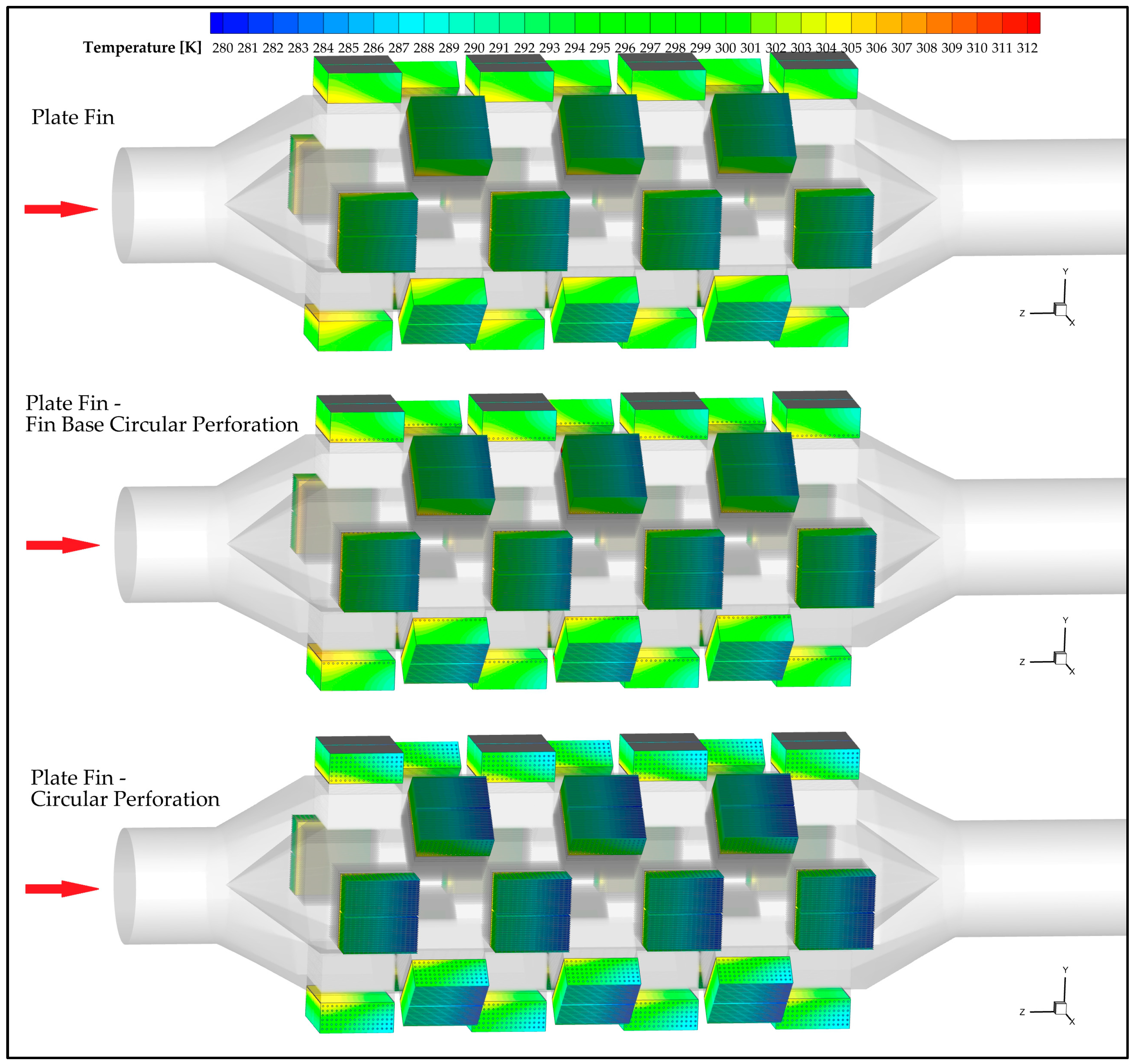
4.1.1. Effect of the Different PF Heat Sinks

When the temperature distributions in Figure 10 are examined, it is seen that the flow regime is improved and the high-temperature regions are more homogeneously distributed owing to the perforations opened on the plate fins (PFs) because in heat sinks with perforated fins, the thermal boundary layer thickness decreases compared to those with non-perforated fins, and therefore the thermal resistance decreases and the amount of heat given the outdoor increases. That is, the perforations create additional flow channels (and therefore turbulence) on the fin surface, increasing heat transfer. Thus, both the average temperature of the fin surface and the cold surface temperature of the TEG module decrease.
Compared to the PF, the PF-FBCP and PF-CP heat sinks caused improvements in the TEM surface temperatures: For the PF-FBCP, the cold surface temperature decreased by approximately 0.3% compared to PF; a similar decrease in the hot surface temperature (~1 K) was observed. These decreases increased the output voltage and thermal efficiency of the TEG modules. For example, the output voltage and thermal efficiency per module in the PF-CP increased by approximately 2–4% compared to the PF. As a result of this increase, the total TEG output power at the PF-CP configuration increased by 4.2%. In addition, the power increase obtained with the PF-FBCP design was 0.6%.

4.1.2. Effect of Open-Cell Aluminum Foam Heat Sinks with Different PPI Values

The surface areas per unit volume of the metal foams with different PPI values are considerably higher than those of the different PF designs used in this study. The increase in the surface area means that higher heat conduction is achieved according to the Fourier heat conduction law.
Temperature distributions for 10, 20 and 40 PPI open-cell aluminum foam heat sinks are presented in Figure 11. Although the average temperature values of the heat sinks are lower at higher PPIs due to the increased surface areas per unit volume, the flow resistance also increases significantly, that is, the TEG modules cold surfaces are cooler at 40 PPI compared to 10 and 20 PPI (Figure 11).
As seen in Figure 12, the higher surface areas per unit volume of open-cell aluminum foams compared to other heat sinks used in this study provided increased heat transfer from the cold surfaces of the TEG modules to the outdoor. In other words, using 10 PPI instead of PF increased the TE power generation by approximately 11%. A similar increase of approximately 11% was also observed for 20 and 40 PPI.

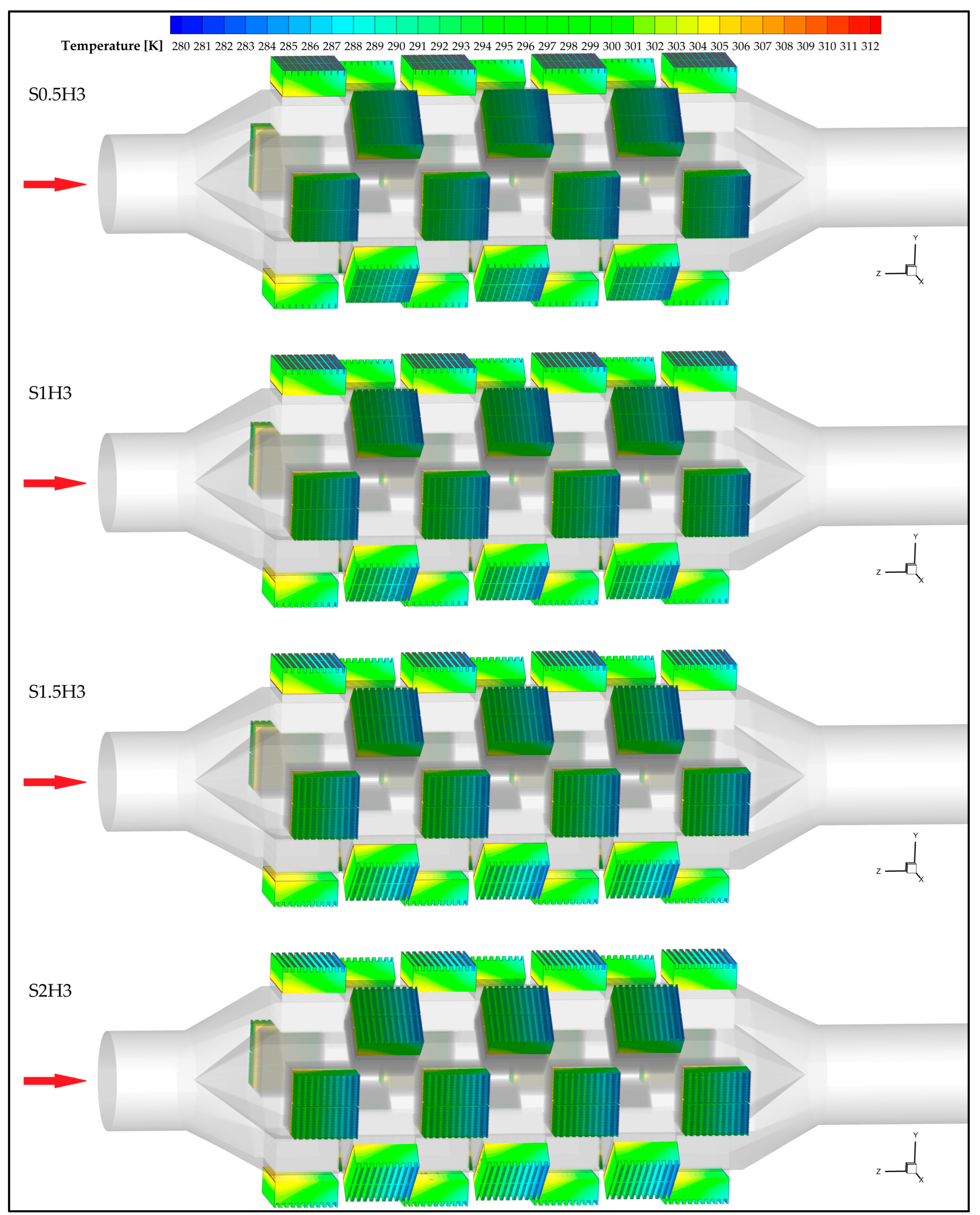
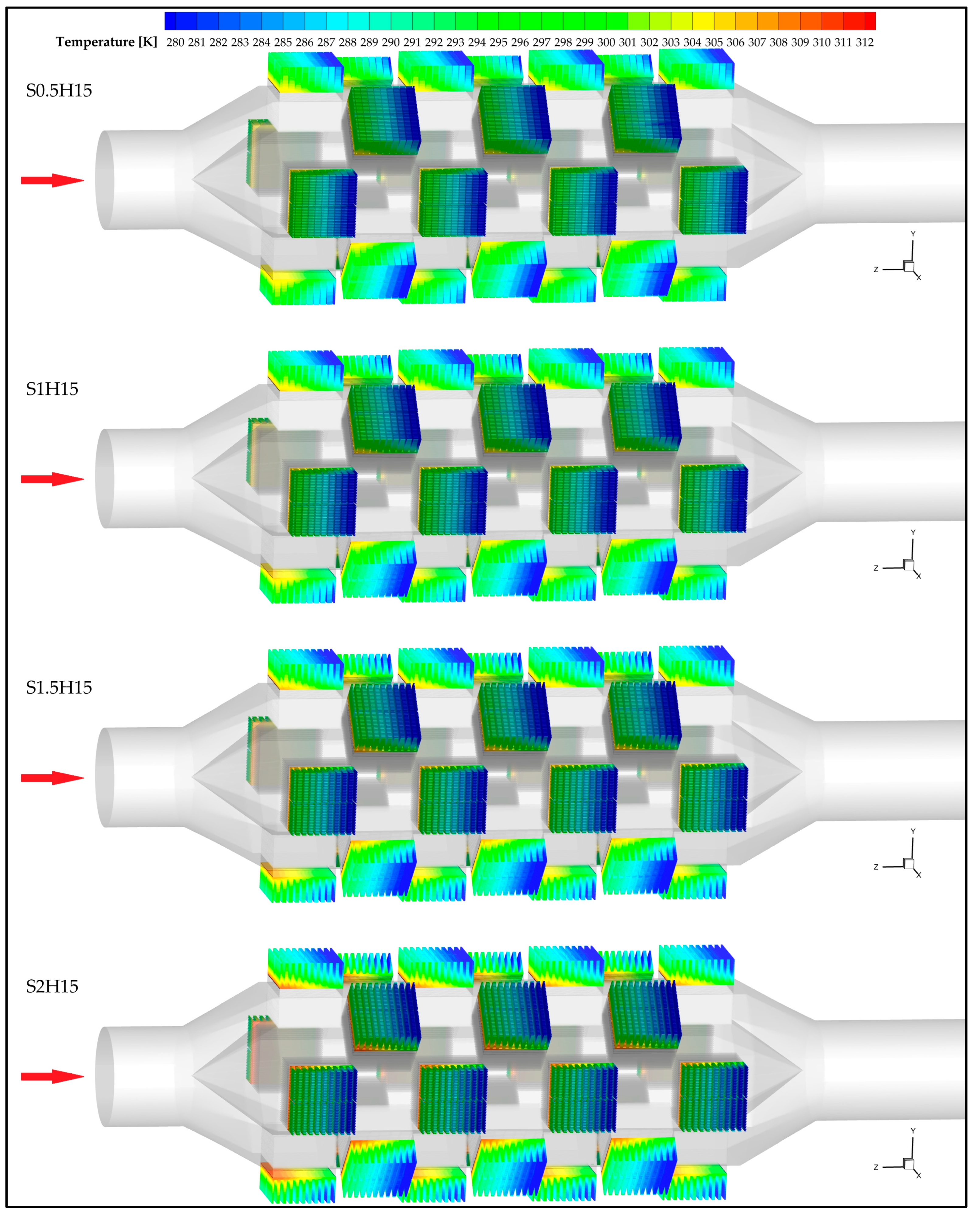
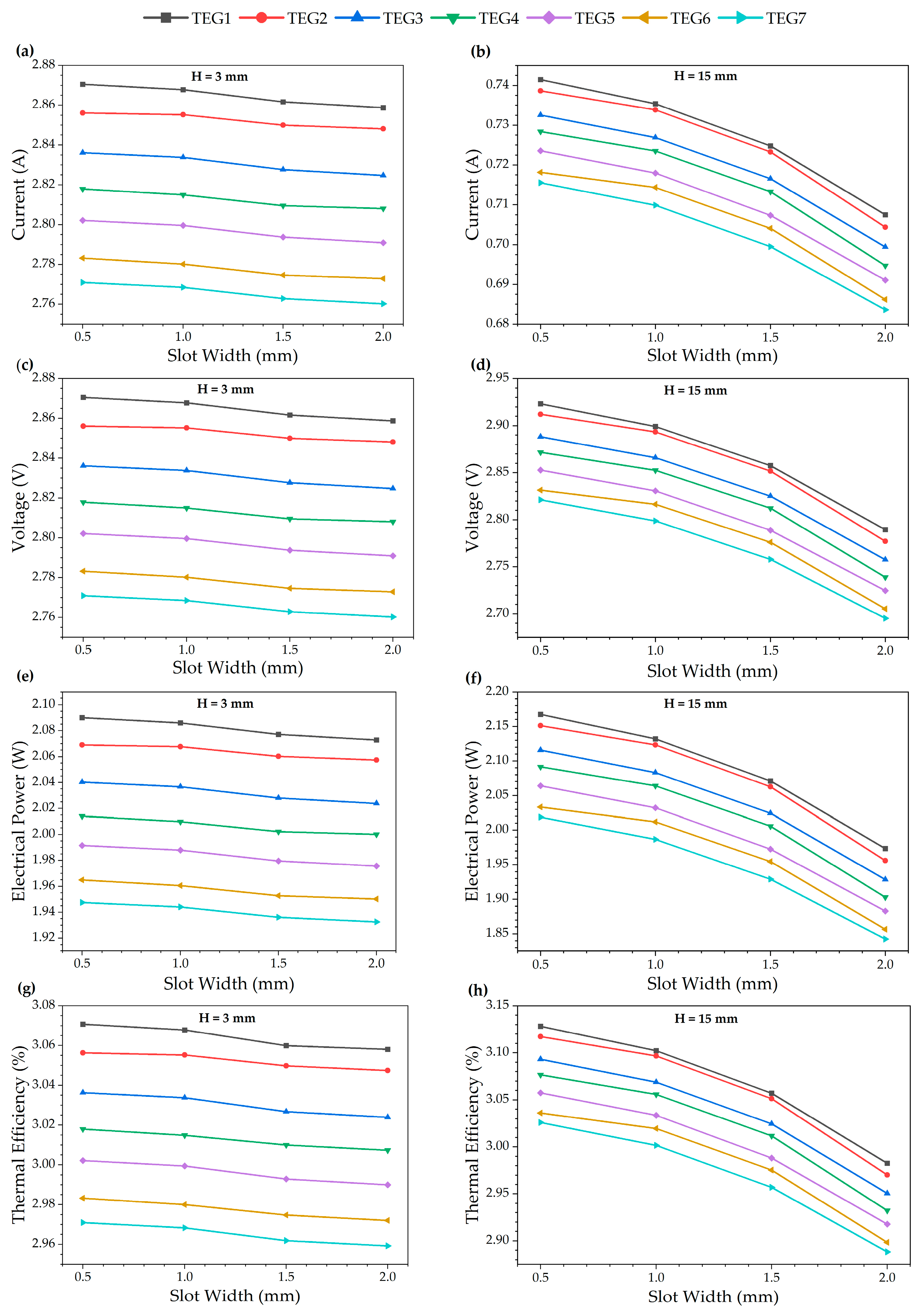
4.1.3. Effect of Slotted PF Heat Sinks with Different Slot Widths and Heights

In the present study, slots with different slot widths and slot heights are opened on the PF fins to provide boundary layer separation. Owing to these slots, both the thermal resistance decreases compared to the ones without slots and vortices are provided. In this case, more heat is transferred from the cold surface of the TEG to the outdoor compared to the PF fins without slots, and thus the thermal efficiency of the TEG increases compared to the ones without slots.
Figure 12 and Figure 13 show the temperature distributions of TEG modules with heat sinks of different slot widths (0.5, 1, 1.5, and 2 mm) for H = 3 mm and H = 15 mm, respectively.
Figure 14 shows the effect of slot width on the performance values of each TEG module (see Figure 1b for their location on the TEG system) for slot heights of 3 mm (Figure 14a,c,e,g), and 15 mm (Figure 14b,d,f,h).
The slot width and height of the slotted PF heat sinks are parameters that significantly affect the performance of TEG modules. For H = 3 mm, as the slot width decreases, an improvement in the amount of heat transferred from the cold surface of the module to the outdoor and hence in the TEG module performance was observed compared to other heat sink designs used in this study. For example, the total TEG output power obtained in the design with the 0.5 mm slot width (S0.5H3) was approximately 2.4% higher compared to PF. This increase was 1.6% for S2H3 heat sink (see Figure 5 for heat sinks with different slot widths and heights). In other words, for H = 3 mm, as the slot width decreased, the heat transfer contact time increased due to the larger vortices formed, and thus the cold-surface temperature of the TEG module decreased. In this case, the temperature difference between the hot- and cold-surfaces increased. This was observed as an increase in the output voltage of the module and therefore in its thermal efficiency: According to PF, voltage increased by approximately 1–2% and thermal efficiency increased by 1% for S0.5H3.
It was determined that the increase in the performance values of the TEG modules with decreasing slot width was greater at H = 15 mm compared to H = 3 mm (Figure 15). This was due to the faster boundary layer separation and larger vortices at H = 15 mm. According to the analysis results, it was determined that the total TEG output power, output voltage and thermal efficiency obtained for S0.5H15 compared to PF were 6.2%, about 3% and about 5% higher, respectively.

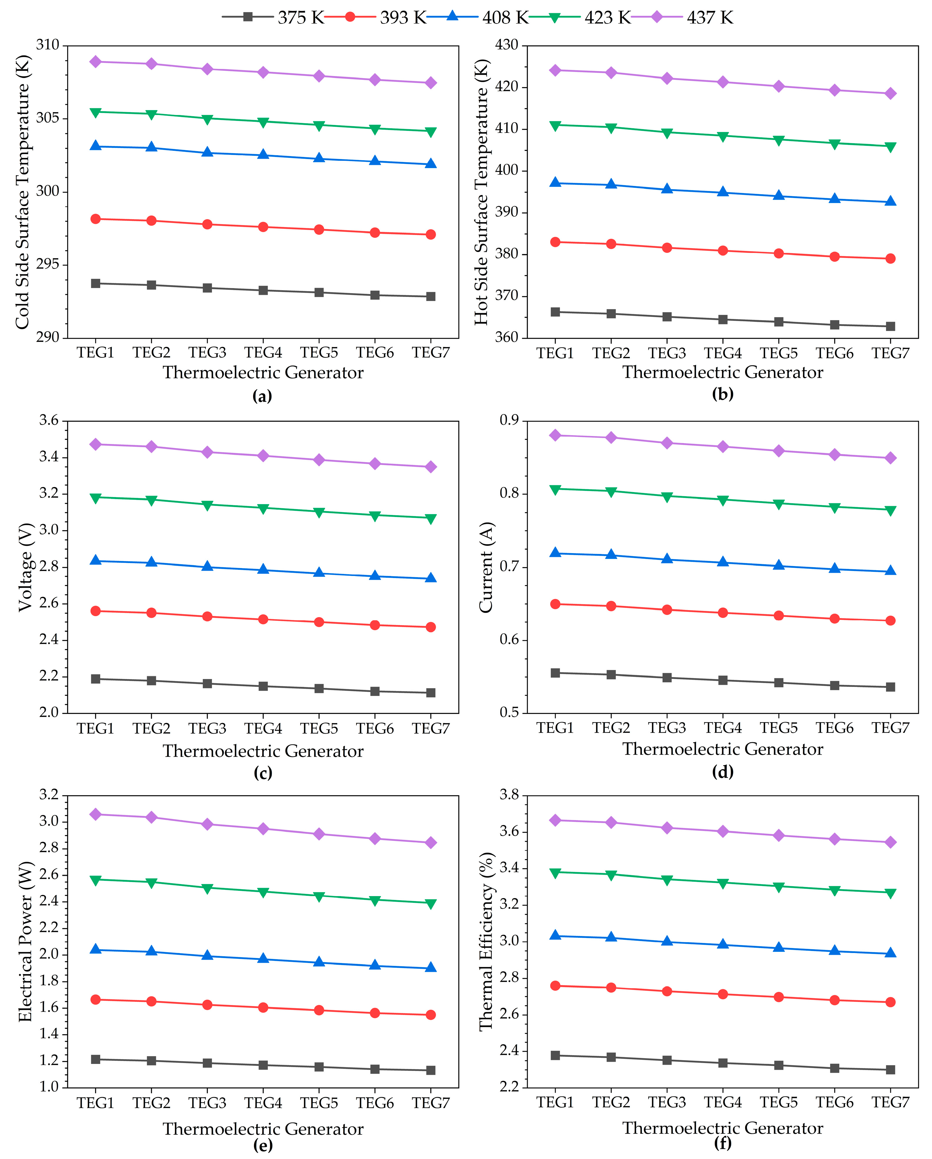
4.2. Performance Analysis of TEG Modules According to Their Location in the System

For the different heat sinks, the performance characteristics of seven TEG modules placed at different locations were analyzed in detail (Figure 15). TEG1 is located closest to the exhaust gas inlet (turbine inlet) and is therefore exposed to the highest temperature compressor air flow. In contrast, TEG7 is located at the outlet end of the TEG system. For the PF heat sink, hot surface temperatures are calculated as 397.122 K for TEG1 and 392.410 K for TEG7. Cold surface temperatures are 303.207 K at TEG1 and 301.755 K at TEG7 due to the fan air flow applied from the opposite direction to the compressor air flow. As a result of this temperature distribution, TEG1 has a larger temperature difference and therefore is the module that produces the highest electrical power output (see Figure 1b for the locations of TEG modules).
A significant decrease in hot- and cold-surface temperatures was observed depending on the locations of the modules. The cold-surface temperatures in modules from TEG1 to TEG7 were determined as 303.207, 303.070, 302.770, 302.357, 302.120, 302.000 and 301.755 K, respectively. The hot-surface temperatures were calculated as 397.122, 396.644, 395.538, 394.028, 393.183, 392.655 and 392.410 K, respectively. Accordingly, the temperature differences obtained in each module were 93.915, 93.574, 92.768, 92.216, 91.671, 91.053 and 90.655 K, respectively (Figure 15a,b). As a result, the decrease in temperature difference across the module array resulted in lower electrical power generation in TEG modules, especially near the output region. This situation revealed that the temperature difference between the hot and cold surfaces of the module directly affects the TEG performance.
The voltage and current values generated in each TEG module varied depending on the location of the module in the system: The voltage values obtained in the modules from TEG1 to TEG7 were 2.835, 2.825, 2.802, 2.786, 2.768, 2.751 and 2.738 V, respectively; the current values were calculated as 0.720, 0.716, 0.710, 0.706, 0.702, 0.697 and 0.694 A (Figure 15c,d), respectively. According to these data, the electrical power values produced by the modules were 2.038, 2.024, 1.991, 1.968, 1.943, 1.919 and 1.901 W, respectively (Figure 15e). These results showed that there was a gradual decrease in voltage and power generation throughout the TEG system due to the decrease in temperature difference. That is, TEG performance is directly dependent on the temperature difference and the location of the module in the TEG system. Additionally, a power difference of approximately 6.7% was observed when comparing the TEG1 and TEG7 modules, clearly demonstrating the influence of module location on electrical power output.

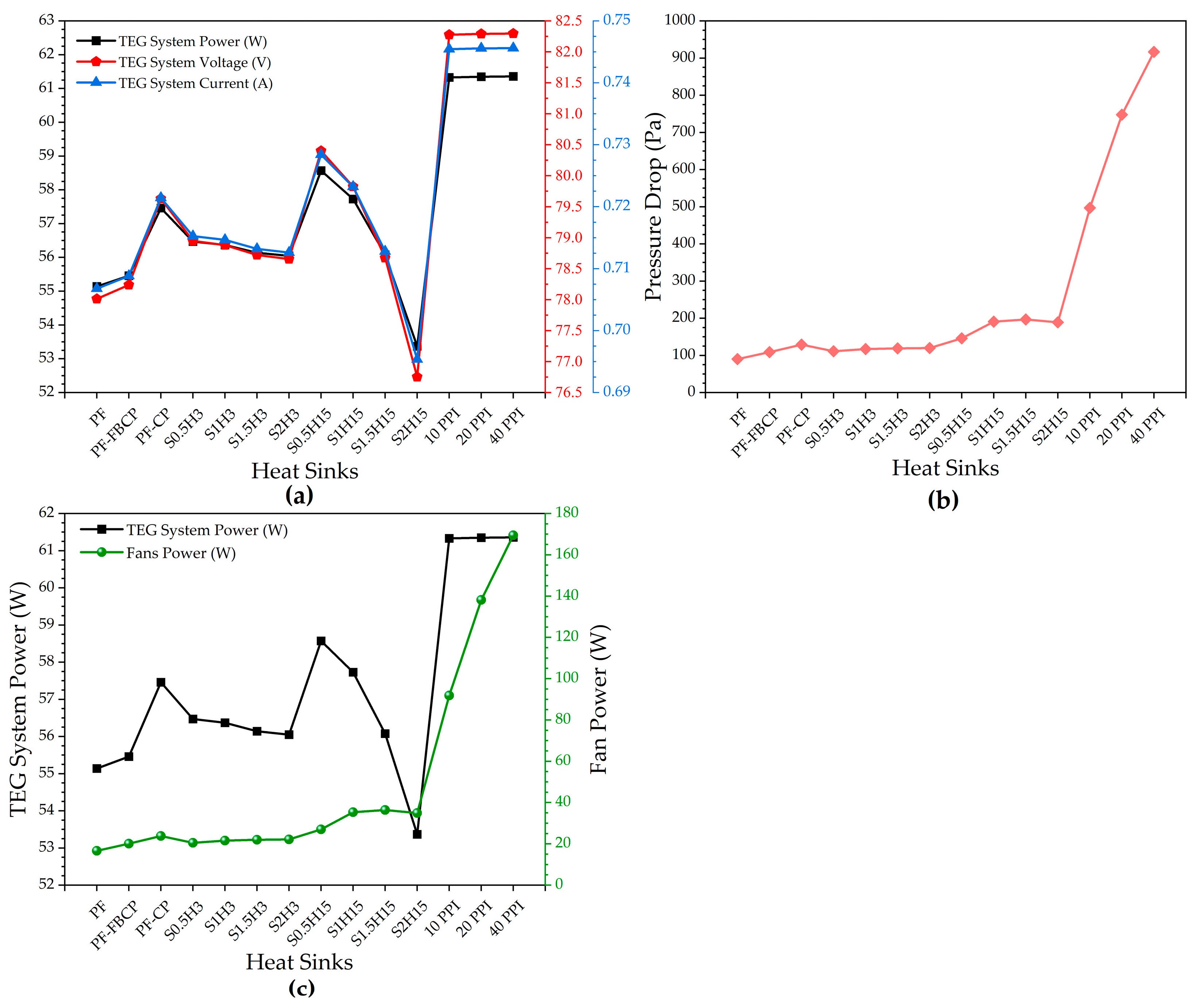
4.3. TEG System Performance, Pressure Drop and Fan Power at Different Heat Sink Designs Used on Cold Surfaces

Figure 16 illustrates the variations in the TEG performance, pressure drop and fan power at different heat sinks.
As seen in Figure 16a, the power, voltage and current values of the TEG system had the highest at 10, 20 and 40 PPI aluminum foams, while these values had the lowest at S2H15 and then at PF. This situation showed that the decrease in heat transfer surface area according to boundary layer separation was more dominant at S2H15. Therefore, compared to other heat sinks, the lowest heat transfer from the cold surface of the TEG module to the outdoor occurred at S2H15. In other words, the lowest temperature difference between the hot and cold surfaces of the TEG module occurred at S2H15 compared to others (Figure 16a,b).
The effects of different heat sinks on the pressure drop on the cold side of the TEG system were also analyzed and it was determined that the PF design had the lowest pressure drop with a pressure drop of 90 Pa compared to the others. In addition, it was determined that the pressure drop values obtained for different heat sinks were close to each other except for aluminum foam (Figure 16b). As seen in Figure 16c, the fan power values required for other heat sinks except aluminum foams were almost close to each other.
Figure 17 shows the changes in TEG system performance for PF with respect to five different compressor outlet air temperatures (375–437 K).
As seen in Figure 17, as the compressor outlet air temperature increased, the voltage, current, electrical power and thermal efficiency values of the TEG modules also increased. This was an expected behavior due to the increase in the temperature difference between the hot and cold sides of the TEG system as the compressor outlet air temperature increased.

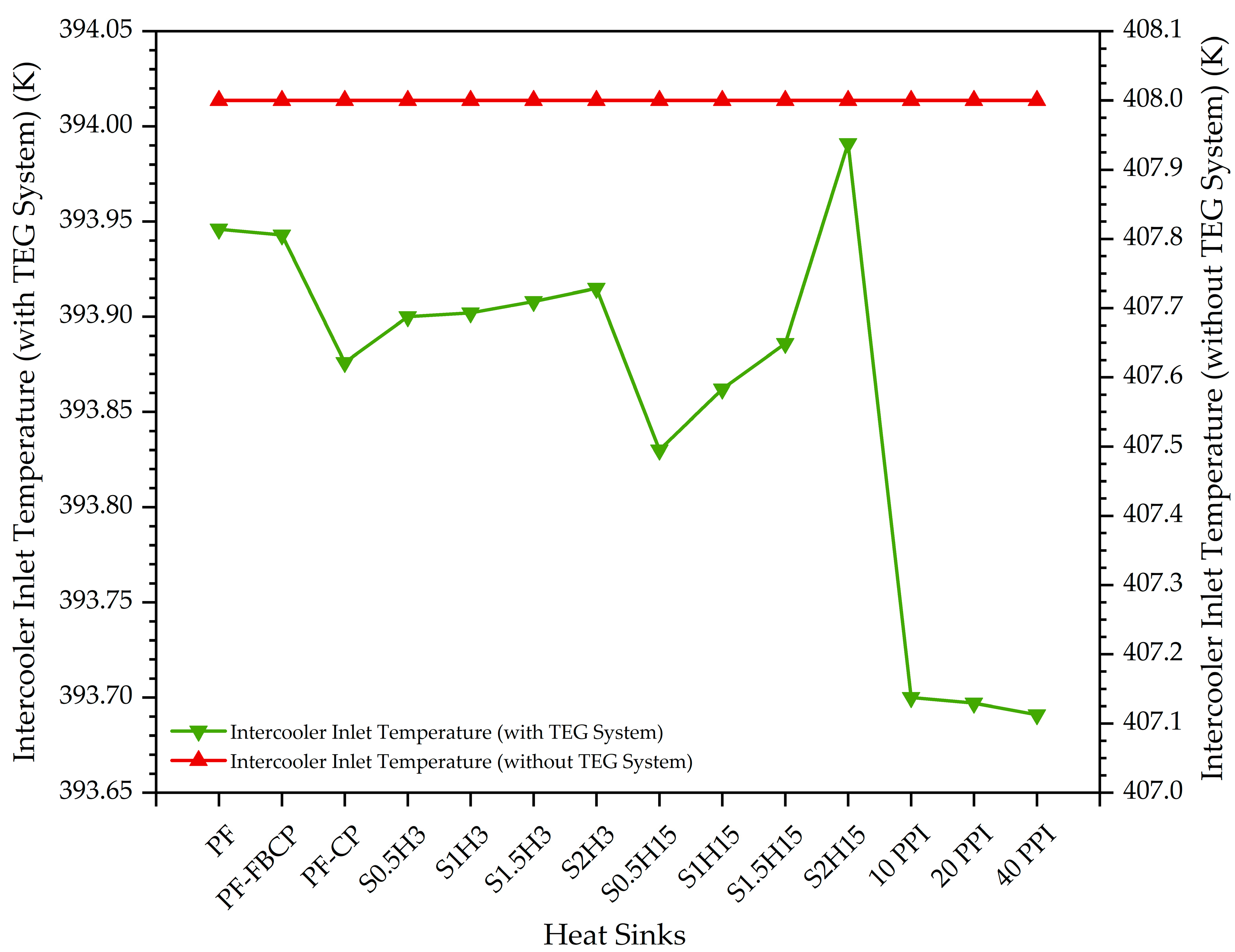
4.4. The Effect of the TEG System with Different Heat Sinks on the Temperature of Intercooler Inlet Air

The effect of the TEG system with different heat sinks on the temperature of intercooler inlet air is shown in Figure 18.
As seen in Figure 18, there was a decrease in the temperatures of intercooler inlet air in the case with the TEG system compared to the temperature of intercooler inlet air in the case without the TEG system. This decrease is important in terms of increasing the engine efficiency of the turbocharged tractor.
In the TEG system with different heat sinks, the maximum decrease in the temperature of intercooler inlet air was obtained with 40 PPI aluminum foam, while the minimum decrease was obtained with S2H15, followed by the case with PF. In addition, in cases with TEG system with different heat sinks, the intercooler inlet air temperatures decreased by approximately 3.4% to 3.5% compared to the case without the TEG system (Figure 18).

5. Conclusions

In this study, new design heat sinks that can transfer more heat from the cold side of the TEG modules to the outdoor were numerically investigated in order to increase the thermal efficiency of a TEG system using compressed air from the compressor of a turbocharged tractor. The results obtained from the numerical study are summarized below:
  • The heat transfer from the cold surface of TEG modules was highest at open-cell aluminum foam heat sinks (10, 20 and 40 PPI). Therefore, the highest performance values (voltage, current, electrical power and thermal efficiency) of TEG modules were obtained in the use of these aluminum foam heat sinks. However, the pressure drop at these heat sinks also increased significantly compared to the others.
  • After aluminum foam heat sinks, the highest performance values of TEG modules were obtained for S0.5H15. The lowest performance values were obtained for S2H15.
  • The total TEG output power, output voltage, and thermal efficiency obtained for S0.5H15 were 6.2%, about 3%, and about 5% higher than those for PF, respectively.
  • For PF-CP, the output voltage and thermal efficiency per module increased by approximately 2–4% compared to PF. As a result of this increase, the total TEG output power for PF-CP increased by 4.2%. In addition, the power increase for PF-FBCP compared to PF was 0.6%.
  • Using 10 PPI instead of PF increased thermoelectric power generation by approximately 11%. A similar increase of approximately 11% was observed for 20 and 40 PPI.
  • The pressure drop values obtained for different heat sinks, except for aluminum foam, were approximately close to each other.
  • The fan power values required for other heat sinks except aluminum foams were almost close to each other.
  • Approximately 6.7% more electrical power was obtained from the TEG1 module than from the TEG7 module.
  • In cases with the TEG system where different heat sinks were used, the intercooler inlet air temperatures decreased by approximately 3.4–3.5% compared to the case without the TEG system.

Author Contributions

Conceptualization, A.G. and G.Y.; methodology, A.G. and G.Y.; software, A.G. and G.Y.; validation, A.G. and G.Y.; formal analysis, A.G. and G.Y.; investigation, A.G.; resources, A.G. and G.Y.; data curation, A.G. and G.Y.; writing—original draft preparation, A.G. and G.Y.; writing—review and editing, A.G. and G.Y.; visualization, A.G. and G.Y.; supervision, A.G. and G.Y. All authors have read and agreed to the published version of the manuscript.

Funding

This research received no external funding.

Data Availability Statement

Data used in this study are available upon request.

Conflicts of Interest

The authors declare no conflicts of interest.

References

  1. Wolf, M.; Rybakov, A.; Hinterding, R.; Feldhoff, A. Geometry Optimization of Thermoelectric Modules: Deviation of Optimum Power Output and Conversion Efficiency. Entropy 2020, 22, 1233. [Google Scholar] [CrossRef] [PubMed]
  2. He, W.; Guo, R.; Liu, S.; Zhu, K.; Wang, S. Temperature gradient characteristics and effect on optimal thermoelectric performance in exhaust power-generation systems. Appl. Energy 2020, 261, 114366. [Google Scholar] [CrossRef]
  3. Sofyan, S.E.; Bahri, S. The performance of thermoelectric exhaust heat recovery system considering different heat source’s fin arrangements. IOP Conf. Ser. Earth Environ. Sci. 2020, 463, 012022. [Google Scholar] [CrossRef]
  4. Kober, M.; Knobelspies, T.; Rossello, A.; Heber, L. Thermoelectric Generators for Automotive Applications: Holistic Optimization and Validation by a Functional Prototype. J. Electron. Mater. 2020, 49, 2902–2909. [Google Scholar] [CrossRef]
  5. Karana, D.R.; Sahoo, R.R. Performance assessment of the automotive heat exchanger with twisted tape for thermoelectric based waste heat recovery. J. Clean. Prod. 2021, 283, 124631. [Google Scholar] [CrossRef]
  6. Karana, D.R.; Sahoo, R.R. An experimental study on the thermal behavior of aluminum thermoelectric system integrated with engine exhaust. Exp. Heat Transf. 2021, 34, 201–216. [Google Scholar] [CrossRef]
  7. Krishna Kumar, T.S.; Anil Kumar, S.; Kodanda Ram, K.; Raj Goli, K.; Siva Prasad, V. Analysis of thermo electric generators in automobile applications. Mater. Today Proc. 2021, 45, 5835–5839. [Google Scholar] [CrossRef]
  8. Liao, T.; Xiao, J.; Xu, Y.; Lin, B. Thermal-electrical coupling properties and optimum analysis of a vehicle exhaust driven thermoelectric system. Therm. Sci. Eng. Prog. 2021, 25, 101040. [Google Scholar] [CrossRef]
  9. Cózar, I.R.; Pujol, T.; Massaguer, E.; Massaguer, A.; Montoro, L.; González, J.R.; Comamala, M.; Ezzitouni, S. Effects of Module Spatial Distribution on the Energy Efficiency and Electrical Output of Automotive Thermoelectric Generators. Energies 2021, 14, 2232. [Google Scholar] [CrossRef]
  10. Zhou, W.; Yang, J.; Qin, Q.; Zhu, J.; Xu, S.; Luo, D.; Wang, R. Research on Module Layout and Module Coverage of an Automobile Exhaust Thermoelectric Power Generation System. Energies 2022, 15, 987. [Google Scholar] [CrossRef]
  11. Nonthakarn, P.; Ekpanyapong, M.; Nontakaew, U.; Bohez, E. Design and Optimization of an Integrated Turbo-Generator and Thermoelectric Generator for Vehicle Exhaust Electrical Energy Recovery. Energies 2019, 12, 3134. [Google Scholar] [CrossRef]
  12. Kalteh, M.; Akhlaghi Garmejani, H. Investigating the influence of Thomson effect on the performance of a thermoelectric generator in a waste heat recovery system. Int. J. Green Energy 2019, 16, 917–929. [Google Scholar] [CrossRef]
  13. Subramaniam, H.; Sivaprahasam, D.; Gopalan, R.; Govindan, S. Design and development of a test rig for the performance evaluation of automotive exhaust thermoelectric generator. AIP Adv. 2019, 9, 065004. [Google Scholar] [CrossRef]
  14. Al-Nimr, M.d.A.; Alajlouni, A.A. Internal combustion engine waste heat recovery by a thermoelectric generator inserted at combustion chamber walls. Int. J. Energy Res. 2018, 42, 4853–4865. [Google Scholar] [CrossRef]
  15. Temizer, İ. Produce Electricity from Exhaust Gases in the Vehicles Used Thermoelectric Generator. Master’s Thesis, Fırat University, Elazığ, Türkiye, 2014. [Google Scholar]
  16. Gürcan, A.; Yakar, G. Investigation of the performance of a thermoelectric generator system utilizing the thermal energy of air compressed in a compressor. J. Korean Phys. Soc. 2022, 80, 467–483. [Google Scholar] [CrossRef]
  17. Gürcan, A.; Yakar, G. Improving the performance of a thermoelectric generator system utilizing the thermal energy of air compressed in the compressor of a turbocharged tractor based on different-sized modules. J. Braz. Soc. Mech. Sci. Eng. 2022, 44, 360. [Google Scholar] [CrossRef]
  18. Sahin, B.; Demir, A. Thermal performance analysis and optimum design parameters of heat exchanger having perforated pin fins. Energy Convers. Manag. 2008, 49, 1684–1695. [Google Scholar] [CrossRef]
  19. Sahin, B.; Demir, A. Performance analysis of a heat exchanger having perforated square fins. Appl. Therm. Eng. 2008, 28, 621–632. [Google Scholar] [CrossRef]
  20. Dhanawade, K.H.; Sunnapwar, V.K.; Dhanawade, H.S. Thermal Analysis of Square and Circular Perforated Fin Arrays by Forced Convection. Int. J. Curr. Eng. Technol. 2013, 2, 109–114. [Google Scholar] [CrossRef]
  21. Al-Sallami, W.; Al-Damook, A.; Thompson, H.M. A numerical investigation of thermal airflows over strip fin heat sinks. Int. Commun. Heat Mass Transf. 2016, 75, 183–191. [Google Scholar] [CrossRef]
  22. Al-Damook, A.; Kapur, N.; Summers, J.L.; Thompson, H.M. Computational design and optimisation of pin fin heat sinks with rectangular perforations. Appl. Therm. Eng. 2016, 105, 691–703. [Google Scholar] [CrossRef]
  23. Chang, S.-W.; Wu, H.-W.; Guo, D.-Y.; Shi, J.-j.; Chen, T.-H. Heat transfer enhancement of vertical dimpled fin array in natural convection. Int. J. Electr. Energy 2017, 106, 781–792. [Google Scholar] [CrossRef]
  24. Haghighi, S.S.; Goshayeshi, H.R.; Safaei, M.R. Natural convection heat transfer enhancement in new designs of plate-fin based heat sinks. Int. J. Electr. Energy 2018, 125, 640–647. [Google Scholar] [CrossRef]
  25. Kim, T.Y.; Kim, S.J. Fluid flow and heat transfer characteristics of cross-cut heat sinks. Int. J. Electr. Energy 2009, 52, 5358–5370. [Google Scholar] [CrossRef]
  26. Gupta, A.; Kumar, M.; Patil, A.K. Enhanced heat transfer in plate fin heat sink with dimples and protrusions. Heat Mass Transf. 2019, 55, 2247–2260. [Google Scholar] [CrossRef]
  27. Khudhur, D.S.; Al-Zuhairy, R.C.; Kassim, M.S. Thermal analysis of heat transfer with different fin geometry through straight plate-fin heat sinks. Int. J. Therm. Sci. 2022, 174, 107443. [Google Scholar] [CrossRef]
  28. Liu, J.; Xu, M.; Guo, W.; Xi, W.; Liu, C.; Sunden, B. Flow and heat transfer mechanism of a regenerative cooling channel mounted with pin-fins using supercritical CO2 as coolant. Int. J. Therm. Sci. 2025, 208, 109425. [Google Scholar] [CrossRef]
  29. Liu, J.; Guo, W.; Yin, M.; Xi, W.; Sunden, B. Flow and heat transfer characteristic of regenerative cooling channels using supercritical CO2 with circular tetrahedral lattice structures. Case Stud. Therm. Eng. 2025, 71, 106204. [Google Scholar] [CrossRef]
  30. T’Jollyn, I.; Pujol, T.; Paepe, M.D.; Massaguer, A.; Montoro, L. Plate fin heat sink modelling and design considerations for thermoelectric generators. Renew. Energy Power Qual. J. 2017, 1, 551–556. [Google Scholar]
  31. Rezania, A.; Rosendahl, L.A. A comparison of micro-structured flat-plate and cross-cut heat sinks for thermoelectric generation application. Energy Convers. Manag. 2015, 101, 730–737. [Google Scholar] [CrossRef]
  32. Barma, M.C.; Riaz, M.; Saidur, R.; Long, B.D. Estimation of thermoelectric power generation by recovering waste heat from Biomass fired thermal oil heater. Energy Convers. Manag. 2015, 98, 303–313. [Google Scholar] [CrossRef]
  33. Wiriyasart, S.; Naphon, P. Heat spreading of liquid jet impingement cooling of cold plate heat sink with different fin shapes. Case Stud. Therm. Eng. 2020, 20, 100638. [Google Scholar] [CrossRef]
  34. Barma, M.C.; Riaz, M.; Saidur, R.; Long, B.D. Waste Heat Recovery by Thermoelectric Generator from Thermal Oil Heater Exhaust. Int. J. Electr. Energy 2015, 3, 235–238. [Google Scholar] [CrossRef]
  35. Xue, W.; Cao, X.; Zhang, G.; Tan, G.; Liu, Z.; Li, K. Structural Optimization of Heat Sink for Thermoelectric Conversion Unit in Personal Comfort System. Energies 2022, 15, 2781. [Google Scholar] [CrossRef]
  36. Pujol, T.; T’Jollyn, I.; Massaguer, E.; Massaguer, A.; Cózar, I.R.; De Paepe, M. Design optimization of plate-fin heat sink with forced convection for single-module thermoelectric generator. Appl. Therm. Eng. 2023, 221, 119866. [Google Scholar] [CrossRef]
  37. Pouryoussefi, S.M.; Zhang, Y. Experimental Study of Air-Cooled Parallel Plate Fin Heat Sinks with and without Circular Pin Fins between the Plate Fins. J. Appl. Fluid Mech. 2015, 8, 515–520. [Google Scholar] [CrossRef]
  38. Rezania, A.; Yousefi, E.; Nejad, A.A. Zero-cooling energy thermoelectric system by phase change material heat sink integrated with porous copper foam. J. Energy Storage 2023, 59, 106507. [Google Scholar] [CrossRef]
  39. Li, W.Q.; Zhang, T.Y.; Li, B.B.; Xue, Z.R.; Wang, H.; Zhang, D. Enhanced energy management performances of passive cooling, heat storage and thermoelectric generator by using phase change material saturated in metal foam. Int. J. Therm. Sci. 2023, 184, 107869. [Google Scholar] [CrossRef]
  40. Wang, T.; Luan, W.; Wang, W.; Tu, S.-T. Waste heat recovery through plate heat exchanger based thermoelectric generator system. Appl. Energy 2014, 136, 860–865. [Google Scholar] [CrossRef]
  41. Yousefi, E.; Abbas Nejad, A.; Sayyar, N. A new approach for simultaneous thermal management of hot and cold sides of thermoelectric modules. Appl. Therm. Eng. 2023, 233, 121156. [Google Scholar] [CrossRef]
  42. Kaul, S.; Joshi, T.; Varshney, L. Analysis of hot air duct between turbocharger and intercooler. Mater. Today Proc. 2021, 43, 719–725. [Google Scholar] [CrossRef]
  43. Xu, C.; Zhuang, Y.; Qian, Y.; Cho, H. Effect on the performance and emissions of methanol/diesel dual-fuel engine with different methanol injection positions. Fuel 2022, 307, 121868. [Google Scholar] [CrossRef]
  44. Tauzia, X.; Maiboom, A.; Shah, S.R. Experimental study of inlet manifold water injection on combustion and emissions of an automotive direct injection Diesel engine. Energy 2010, 35, 3628–3639. [Google Scholar] [CrossRef]
  45. Di Battista, D.; Di Bartolomeo, M.; Cipollone, R. Flow and thermal management of engine intake air for fuel and emissions saving. Energy Convers. Manag. 2018, 173, 46–55. [Google Scholar] [CrossRef]
  46. Gürcan, A. Recovery of Exhaust Heat Energy Using Thermoelectric Generators in Different Sizes. Master’s Thesis, Pamukkale University, Denizli, Türkiye, 2019. [Google Scholar]
  47. Potur, R.A. Mathematical Modelling of an Actual Cycle and Determining the Optimum Combustion Law Relating to Design of a Diesel Tractor Engine Suited for Stage IIIB Emission Standard. Masters’s Thesis, İstanbul Technical University, İstanbul, Türkiye, 2009. [Google Scholar]
  48. Kryotherm. Low Temperature Generating Modules. Available online: https://kryothermtec.com/low-temperature-generating-modules.html (accessed on 5 February 2024).
  49. Luo, D.; Wang, R.; Yu, W.; Zhou, W. Performance evaluation of a novel thermoelectric module with BiSbTeSe-based material. Appl. Energy 2019, 238, 1299–1311. [Google Scholar] [CrossRef]
  50. Kryotherm. Specification of Generating Thermoelectric Modules TGM-199-1.4-2.0. Available online: http://kryothermtec.com/assets/dir2attz/ru/TGM-199-1.4-2.0.pdf (accessed on 5 February 2024).
  51. Lee, H. Thermoelectrics: Design and Materials; Wiley: Chichester, UK, 2017. [Google Scholar]
  52. Menter, F.R. Two-equation eddy-viscosity turbulence models for engineering applications. AIAA J. 1994, 32, 1598–1605. [Google Scholar] [CrossRef]
  53. Ansys. Ansys Fluent Theory Guide; Ansys, Inc.: Canonsburg, PA, USA, 2024; pp. 60–68. [Google Scholar]
  54. Ansys. Ansys Fluent User Guide; Ansys, Inc.: Canonsburg, PA, USA, 2024; pp. 1305–1342. [Google Scholar]
  55. Doğan, A.; Pırasacı, T.; Gören, A. Numerical Investigation of Mixed Convection Heat Transfer from Porous Blocks in a Channel. Mühendis Ve Makina 2013, 54, 33–38. [Google Scholar]
  56. Wang, R.; Meng, Z.; Luo, D.; Yu, W.; Zhou, W. A Comprehensive Study on X-Type Thermoelectric Generator Modules. J. Electron. Mater. 2020, 49, 4343–4354. [Google Scholar] [CrossRef]
  57. Liao, M.; He, Z.; Jiang, C.; Fan, X.a.; Li, Y.; Qi, F. A three-dimensional model for thermoelectric generator and the influence of Peltier effect on the performance and heat transfer. Appl. Therm. Eng. 2018, 133, 493–500. [Google Scholar] [CrossRef]
  58. Chen, M.; Rosendahl, L.A.; Condra, T. A three-dimensional numerical model of thermoelectric generators in fluid power systems. Int. J. Electr. Energy 2011, 54, 345–355. [Google Scholar] [CrossRef]
  59. Eldesoukey, A.; Hassan, H. 3D model of thermoelectric generator (TEG) case study: Effect of flow regime on the TEG performance. Energy Convers. Manag. 2019, 180, 231–239. [Google Scholar] [CrossRef]
  60. Fallah Kohan, H.R.; Eslami, M.; Jafarpur, K. A hybrid analytical-computational method for three dimensional modeling of thermoelectric generators. Int. J. Energy Res. 2021, 45, 2680–2693. [Google Scholar] [CrossRef]
Figure 1. Schematic structure of a TEG system that uses the thermal energy of compressed air. (a) turbocharge and TEG system and (b) locations of TED modules.
Energies 18 03267 g001
Figure 2. (a) Positioning of TEMs on the octagonal pipe, (b) geometric dimensions of the deflector inside the octagonal pipe.
Energies 18 03267 g002
Figure 3. Schematic structure and dimensions of the TEG module used in this study.
Energies 18 03267 g003
Figure 4. Simplified TEG system model for turbocharged tractor.
Energies 18 03267 g004
Figure 5. Different heat sink designs examined in the study: plate fin (PF) heat sink, plate fin—fin base circular perforation (PF-FBCP) heat sink, plate fin—circular perforation (PF-CP) heat sink, open-cell aluminum foam heat sink and slotted plate fin heat sinks (S0.5H3–S2H15).
Energies 18 03267 g005
Figure 6. Boundary conditions of the TEG system for Ansys-Fluent.
Energies 18 03267 g006
Figure 7. Poly-hexcore mesh of TEG system.
Energies 18 03267 g007
Figure 8. Pressure, temperature and velocity distributions in a regular octagonal pipe.
Energies 18 03267 g008
Figure 9. Validation of TEG system model of turbocharged tractor: (a) first validation, (b) second validation and (c) third validation.
Energies 18 03267 g009
Figure 10. Temperature distributions for PF, PF-FBCP and PF-CP heat sinks.
Energies 18 03267 g010
Figure 11. Temperature distributions of 10, 20 and 40 PPI open-cell aluminum foam heat sinks.
Energies 18 03267 g011
Figure 12. Temperature distributions of TEG modules with heat sinks of different slot widths for a fixed slot height (H = 3 mm).
Energies 18 03267 g012
Figure 13. Temperature distributions of TEG modules with heat sinks of different slot widths for a fixed slot height (H = 15 mm).
Energies 18 03267 g013
Figure 14. Effect of slot width and height on TEG performance: (a) current for H = 3 mm, (b) current for H = 15 mm, (c) voltage for H = 3 mm, (d) voltage for H = 15 mm, (e) electrical power for H = 3 mm (f) electrical power for H = 15 mm (g) thermal efficiency for H = 3 mm and (h) thermal efficiency for H = 15 mm.
Energies 18 03267 g014
Figure 15. Effect of different heat sinks on the performance of TEG modules: (a) cold-surface temperatures, (b) hot-surface temperatures, (c) voltage, (d) current, (e) electrical power, (f) thermal efficiency values.
Energies 18 03267 g015
Figure 16. TEG system performances (a), pressure drops (b) and fan powers (c) of different heat sink designs for 408 K compressor outlet air.
Energies 18 03267 g016
Figure 17. TEG system performances for PF according to five different compressor outlet air temperatures: (a) cold side surface temperature, (b) hot side surface temperature, (c) voltage, (d) current, (e) electrical power and (f) thermal efficiency.
Energies 18 03267 g017
Figure 18. Effect of TEG system with different heat sinks on intercooler inlet temperatures.
Energies 18 03267 g018
Table 1. Thermophysical properties of compressor air.
ParameterCompressor Air
Density d (kg/m3)Ideal gas
Specific heat
Cp (J/kgK)
F o r   100   K T 1000   K :
C p T = 1.573588 × 10 17 T 7 + 6.540196 × 10 14 T 6 1.11109 × 10 10 T 5                                                       + 9.92857 × 10 8 T 4 5.034909 × 10 5 T 3 0.01485511 T 2 2.368819 T                                                       + 1161.482
F o r   1000   K T 3000   K :
C p T = 1.112335 × 10 19 T 7 1.565553 × 10 15 T 6 + 9.237533 × 10 12 T 5                                                       2.936679 × 10 8 T 4 + 5.421615 × 10 5 T 3 0.0581276 T 2 + 33.70605 T                                                       7069.814
Thermal conductivity
k (W/mK)
F o r   t h e   r a n g e   o f   123   K   a n d   2273   K :
                    k T = 4.64 × 10 12 T 3 2.902 × 10 8 T 2 + 9.043 × 10 5 T + 1.017 × 10 3
Dynamic viscosity
μ (kg/ms)
Sutherland Law
Molecular weight (kg/kmol)28.966
Table 2. Component material properties of TEG system.
MaterialComponentParameterValueUnit
AluminumHeat sinks and regular octagonal pipeThermal conductivity202.4W/mK
Specific heat871J/kg·K
Density2719kg/m3
CeramicCeramic plates of TEGThermal conductivity25W/mK
Specific heat880J/kg·K
Density3720kg/m3
CopperCopper slices of TEGThermal conductivity387,6W/mK
Specific heat381J/kg·K
Density8978kg/m3
Electrical conductivity 1.694 × 10 8 Ωm
p-type thermoelectric materialp-type thermoelectric legsThermal conductivity1.5W/mK
Specific heat544J/kg·K
Density7700kg/m3
Electrical conductivity 1.024 × 10 5 Ωm
Seebeck coefficient 162.8 × 10 6 V/K
n-type thermoelectric materialn-type thermoelectric legsThermal conductivity1.5W/mK
Specific heat544J/kg·K
Density7700kg/m3
Electrical conductivity 1.024 × 10 5 Ωm
Seebeck coefficient 162.8 × 10 6 V/K
Table 3. Properties of aluminum foam [55].
Porosity (ε)Pore Per Inch (PPI)P ermeability   ( δ ) [m2]
0.9210 2.36 × 10 7
0.9220 1.06 × 10 7
0.9240 7.15 × 10 8
Table 4. Ansys-Fluent grid analysis of the TEG system.
Grid NumberNumber of Cells∆P (Pa)Error of ∆PIntercooler Inlet Temperature (K)Error of Temperature
121,024,83041,040.1NA393.951NA
217,242,94641,037.920%393.950.00%
39,231,36440,187.672%393.9420.00%
44,614,57836,486.4511%393.9310.01%
51,692,31527,831.0532%393.9230.01%
Table 5. Ansys-Thermal-Electric grid analysis of the TEG system.
Grid NumberElementNodeVoltage (V)Current (A)Power (W)Error of Power
1300,5081,444,7162.8350.7192.038NA
2167,356840,2692.8350.7192.0380
388,422460,4182.8360.7182.0390.05%
Disclaimer/Publisher’s Note: The statements, opinions and data contained in all publications are solely those of the individual author(s) and contributor(s) and not of MDPI and/or the editor(s). MDPI and/or the editor(s) disclaim responsibility for any injury to people or property resulting from any ideas, methods, instructions or products referred to in the content.

