Article

Experimental Investigation into the Energy Performance of a Biomass Recuperative Organic Rankine Cycle (ORC) for Micro-Scale Applications in Design and Off-Design Conditions

Department of Mechanical, Energy and Management Engineering, University of Calabria, 87036 Rende, Italy
*
Author to whom correspondence should be addressed.
Energies 2025, 18(12), 3201; https://doi.org/10.3390/en18123201
Submission received: 11 May 2025 / Revised: 13 June 2025 / Accepted: 15 June 2025 / Published: 18 June 2025

Abstract

:
Increasing energy efficiency and promoting the use of sustainable energy sources are crucial for addressing global energy challenges. Organic Rankine cycle (ORC) technology offers a promising route for efficient decentralised power generation. This study examines the energy performance of a biomass-fired recuperative ORC for micro-scale applications. The investigation proposes an extensive experimental analysis to characterise the ORC behaviour under design and off-design conditions due to the limited data in the literature. The work examines the impact of different operating parameters (e.g., pump speed, hot source temperature, superheating degree, expander inlet pressure) to provide suitable insights for the efficient design and operation of recuperative micro-generation units fuelled by biomass. The experimental analysis highlights that the micro-scale ORC properly operates under a wide range of operating conditions. Electric power ranges between 0.37 kW and 2.30 kW, and the maximum net electric efficiency reaches 8.55%. The selection of the proper operating conditions guarantees efficiency higher than 7% for power larger than 800 W, demonstrating that biomass-fired recuperative ORC systems represent a valuable option for low-carbon micro-scale generation, with good performance in design and off-design conditions. For this purpose, the pump speed and the superheating degree at the expander inlet are essential parameters to maximise the performance of the investigated recuperative ORC.

1. Introduction

The collective efforts to reduce greenhouse gas (GHG) emissions and address climate change have led countries and organisations to reinforce commitments, foster collaboration, and drive innovation to ensure a low-carbon future. This future envisions efficient and optimised energy systems and significantly reduced emissions to limit global warming below 1.5 °C and decrease the dependence on fossil fuels (i.e., coal, oil, and natural gas) [1,2,3,4]. The Paris Agreement and the United Nations Sustainable Development Goals (SDGs) underscore that a rapid transition towards low-carbon energy systems is necessary [5,6]. Specifically, SDG 7—Affordable and Clean Energy highlights the crucial role of clean and efficient energy solutions to provide universal access to reliable, affordable, and modern energy, minimising environmental impacts and contributing to the achievement of other SDGs. The European Union (EU) has also set ambitious goals to reduce GHG emissions, improve energy efficiency, and support renewable energy sources [7,8]. The EU has increased its short-to-mid-term targets for GHG emissions to decrease by 2030 (−55% compared to 1990 levels) [9,10], for the share of renewable energy sources in the gross final energy consumption (at least 42.5%, with a collective endeavour to 45%) [11], and for overall improvement in energy efficiency, reducing the final energy consumption by at least 11.7% compared to the projected value based on the EU 2020 Reference Scenario [12]. These challenges necessarily involve achieving highly efficient energy systems [13]. This also means the reduction in thermal energy waste and exploitation of renewable and low-temperature energy sources that could be used to generate electricity, contributing in a further way to supporting the green transition [14,15,16].
In this framework, the organic Rankine cycle (ORC) represents one of the most suitable technologies for converting waste and renewable and low-temperature sources into electricity [17,18,19], aligning with SDG 7 by promoting the utilisation of clean and renewable sources and enhancing energy efficiency, especially at the local scale. In 2020, the trend of ORC diffusion increased by 40% (+1.18 GW), in terms of installed capacity from 2016, and 46% (+851) in installed plants. The global capacity is close to 4.1 GW, with over 2700 installed ORC systems [20]. The ORC market was evaluated at about USD 14.1 billion in 2022, with a nearly 6.9% compound average growth rate (CAGR) for the successive decade, reaching a USD 27.4 billion outlook by 2032 [21].
Although ORC is an advanced technology for medium- and large-sized applications (above a hundred kilowatts), it remains in its early stage at small scales [22,23,24] and is still in the prototyping phase for micro-generation [25], primarily due to lower efficiencies and higher specific costs compared to larger-scale units [26,27].
The performance of micro-ORC plants is improved through research activities and scientific studies, which also examine the impact of working and ambient factors. Recent investigations have concentrated on developing micro-ORC systems with an electric output lower than 10 kW [28,29], a size particularly appealing in the residential and third sectors [30]. For this purpose, numerous computational [31], theoretical [32], and experimental [33] studies on ORCs have been disclosed. Theoretical and simulation studies are useful for understanding the influence of various operating parameters on system functionality. However, several assumptions are frequently needed, which causes the research findings to diverge from the actual occurrence [34]. Therefore, experimental investigation is crucial for defining accurate performance [35]. Experimental analyses are delving deeply into every aspect of micro-ORCs to enhance their performance, reliability, and cost-effectiveness. In particular, the definition of organic working fluids suitable for efficient energy conversion has received considerable attention [36,37,38], and the selection of the optimal pump and expander configurations has also been thoroughly researched [26,39]. Moreover, the influence of the heat source represents an essential aspect in micro-scale applications [40]. Recent studies primarily focus on hot sources using renewables, such as solar energy [40,41], geothermal sources [42,43], and biomass [32,44]. In this context, the European Union considers biomass a sustainable and suitable energy source with the potential to meet a significant portion of the power and heat requests [45,46]. In particular, sustainable biomass (e.g., forest and agricultural residues, sawmill and industry by-products, recycled wood, etc.) significantly reduces GHG emissions, exploits local sources, increases energy security, transforms waste into resources, and promotes distributed generation and circular economy, compared to fossil fuels (e.g., coal, oil, natural gas) [45]. On the other hand, coal is typically used in large-scale power plants, as its use at a small scale would not justify the high costs of pollutant removal systems required to meet environmental standards [47]. Furthermore, biomass is sometimes co-fired with coal in large-scale power plants to reduce emissions and improve fuel flexibility [48,49]. However, such integrated strategies are not applicable to micro-scale ORC systems, which are designed for decentralised and low-power applications.
The literature review highlights that various experimental campaigns have focused on biomass-fired micro-scale ORC systems to identify optimal operating conditions and maximise power output and efficiency [25,30,50]. In these systems, a secondary circuit, employing thermal oil or water as an auxiliary fluid, usually transfers heat from biomass flue gas to the ORC evaporator [51,52]. In other configurations, flue gas provides direct heating to the ORC working fluid [23,44]. Furthermore, recuperative ORCs offer the possibility of increasing system performance compared to simple setups [53,54] by exploiting the energy of the vapour at the expander exit to pre-heat the working fluid before it enters the evaporator [30,55].
Table 1 summarises experimental works developed in the last few years on biomass-fired ORC units with net power lower than 5 kW, detailing the system configuration (simple, recuperative), heat transfer fluid (thermal oil, water, and flue gas), hot source temperature range, working fluid temperature at the expander entrance, and efficiencies (thermal, electric).
The table shows that the hot source and expander inlet temperatures are typically within limited operational intervals, approximately 20 to 30 °C, and the net electric efficiencies under steady-state conditions are generally lower than 7.5%. As an example, Kaczmarczyk [50] studied the operation of a biomass ORC system integrated with two scroll expanders. The thermal oil temperature ranged from 180 °C to 200 °C and the main results showed that the maximum electric efficiency was 3.1% and 3.3%, with expanders operating in serial mode and in parallel mode, respectively. Carraro et al. [25] investigated the performance of an ORC system using R245fa as the working fluid, with variable thermal oil temperatures (130–150 °C), pump speeds (2050–2450 rpm), and expander speeds (2200–2400 rpm). The study reported that the highest electric efficiency was 7.3%. Villarino et al. [30] tested a micro-cogeneration apparatus using three residual biomasses (i.e., pruning vine, pruning kiwi, and gorse). The results highlighted a maximum electric efficiency of about 9% and a maximum power output of 3.6 kW under unsteady conditions, with hot water temperatures varying between 82 °C and 98 °C during the tests. Qiu et al. [56] investigated a micro-scale biomass ORC and found that the system achieved 1.4% electric efficiency with 0.9 kW electric power output, using hot water in the range between 117.8 °C and 126.6 °C and adopting different pump and expander speeds. Mascuch et al. [34,58] developed different biomass ORC units with nominal electric power ranging between 1 and 5 kW for the direct valorisation of flue gas. The 3.5 kW unit operated with expander inlet temperatures between 155 °C and 166 °C and achieved a maximum net electric power and efficiency equal to 1 kW and 1.5% [58], respectively, while the 2.0 kW ORC system reached a net electric power and efficiency equal to 1.87 kW and 2.5%, with the expander inlet temperature equal to 192 °C [34]. Furthermore, Feng et al. [59] analysed a biomass ORC unit operating with a heat source inlet temperature ranging from 110 to 130 °C, achieving a thermal efficiency between 9.5% and 12.1% and a maximum expander shaft power of about 2 kW.
The literature review demonstrates that enhancing the performance of micro-scale biomass ORC is currently a significant and active research area [60,61]. However, the availability of experimental data remains limited [59], and further investigations are crucial to improve energy efficiency and validate the effective adoption of ORC systems for decentralised power production [22,23]. In particular, to the best of the authors’ knowledge, few experimental works offer comprehensive insights into the behaviour of micro-scale biomass recuperative ORCs, particularly in terms of performance data covering broad temperature ranges and off-design conditions, where efficiency and power output reduce due to part-load phenomena [62]. Consequently, additional studies are essential to address these challenges and improve the applicability of micro-scale apparatus for further development and deployment in real scenarios under varying heat source availability and load demands [63].
This work aims to address this gap and advance the knowledge of biomass-fired recuperative ORC systems by providing comprehensive experimental data, particularly for off-design conditions, and evaluating the ORC suitability and applicability for micro-scale purposes. Therefore, an extensive experimental energy analysis is carried out under several operating regimes, in design and off-design conditions, to characterise the system behaviour even in non-optimal regimes. For this purpose, the work investigates the influence of different operating parameters (e.g., pump speed, hot source temperature, superheating degree) on the performance of micro-scale biomass-fired recuperative ORC across a broad spectrum of working conditions. Consequently, the experimental investigation offers valuable information for enhancing the design and operational strategies of small-scale recuperative biomass-fuelled ORCs, supporting their deployment as effective, reliable, and sustainable solutions for decentralised energy production [64]. Furthermore, the experimental data enable the development and validation of accurate numerical models, particularly for off-design conditions.

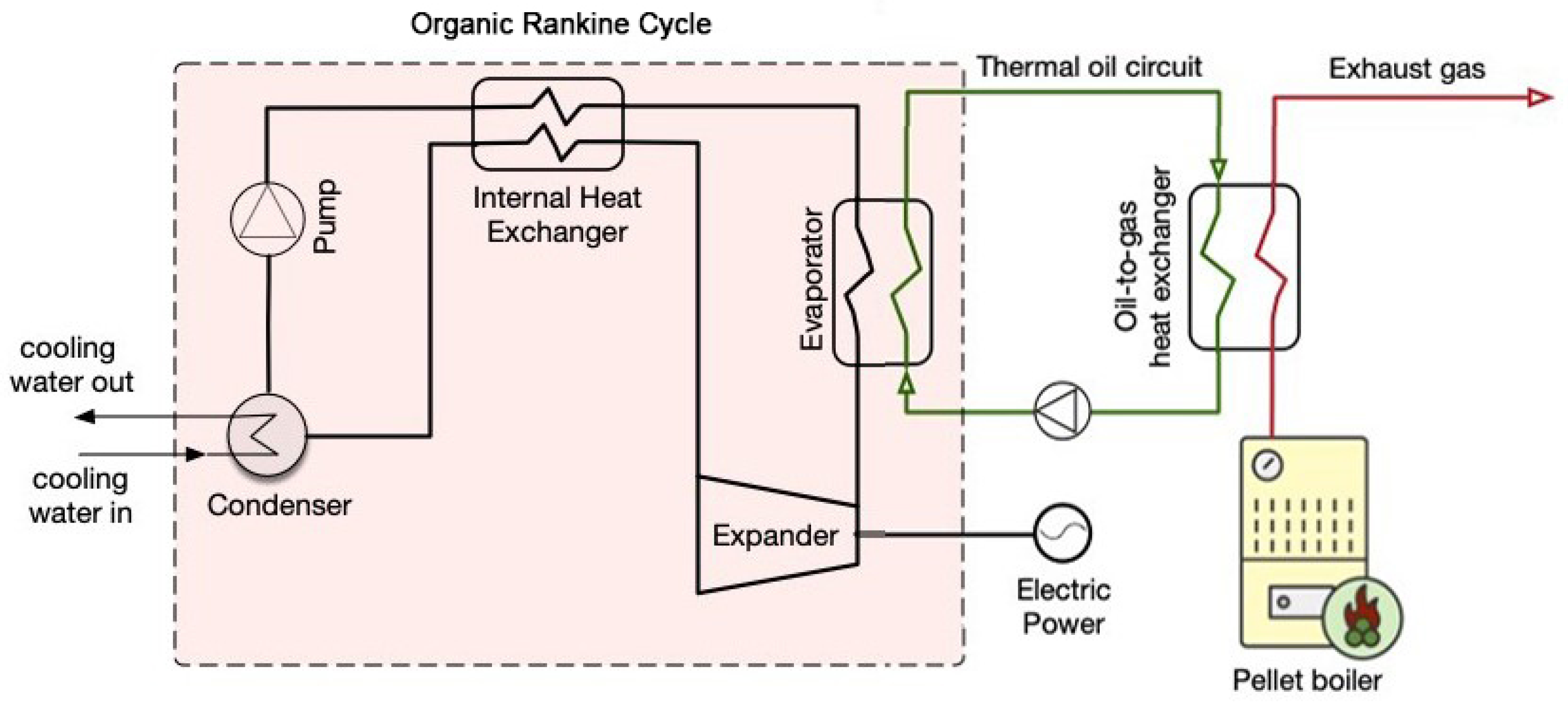
2. Materials and Methods

Figure 1 shows the simplified layout of the investigated biomass micro-scale ORC system, installed at the Fluid Dynamics and Energy Systems Laboratory of the Department of Mechanical, Energy and Management Engineering of the University of Calabria. The apparatus has been designed and developed for residential and third-sector applications. The experimental system comprises a biomass boiler, a diathermic oil circuit, and a recuperative ORC. An ancillary subsystem is the cooling circuit, using tap water as the cold source at the ORC condenser. Furthermore, the cooling water dissipates the thermal energy of the oil through a bypass plate heat exchanger when the ORC shuts off, and ensures safety under critical operating conditions, such as during an ORC sudden shutdown.

2.1. Biomass Boiler

The biomass boiler has a nominal thermal power of 37 kW and preferably uses wood pellets as fuel [65]. Table 2 details the main characteristics of the biomass adopted during the experimental investigations. The boiler apparatus is among the few biomass-fired units commercially available for domestic-scale applications using diathermic oil [25], which allows a maximum set point temperature of 170 °C, preventing overheating risks for the ORC working fluid.

2.2. Thermal Oil Circuit

The selected thermal oil is Therminol SP (Eastman Chemical Company, Kingsport, TN, USA), suitable for moderate-temperature applications up to 300 °C [66]. The fluid is a synthetic diathermic oil in liquid phase for indirect heating processes (Table 3). An oil gear pump, driven by an asynchronous motor, ensures the thermal oil circulation and a frequency driver adjusts the pump speed to the desired value.

2.3. Micro-ORC Unit

Figure 2a highlights the simplified ORC layout, and Figure 2b shows the corresponding typical processes on the temperature–entropy (T-s) diagram. The system is a recuperative unit working in the subcritical region. The main components are a scroll expander, a gear pump, and three brazed plate heat exchangers (i.e., evaporator, internal heat exchanger/recuperator, and condenser).
The pump increases the pressure of the working fluid (in the liquid phase) through the 1–2 process (Figure 2). Subsequently, the recuperator pre-heats the liquid (2–3 process) before entering the evaporator. In the evaporator, the working fluid evaporates, reaching a superheated state and the maximum temperature (3–4 process), exploiting the thermal oil from the biomass boiler as the hot source. The vapour then expands through the scroll expander (4–5 process), producing the mechanical energy that the generator converts into electricity. The working fluid then enters the recuperator, where the temperature progressively reduces (5–6 process) due to the heat exchange with the working fluid in the liquid phase (2–3 process). At the recuperator exit, the vapour moves to the condenser to transition into the liquid phase (6–1 process). For this purpose, water is used as the cold source for the ORC condenser. The system uses R245fa, a widely adopted working fluid in commercial ORC systems, due to its suitability with medium-low temperature thermal sources up to 190 °C [67,68,69].
The working fluid, whose main characteristics are in Table 4, is non-flammable, with zero ozone depletion potential (ODP) and low toxicity and global warming potential (GWP) [30]. Furthermore, R245fa exhibits high compatibility with the typical construction materials of the ORC system, with high reliability and low specific investment cost [22,68]. The ORC shows compactness (175 × 60 × 45 cm) and simplicity for the direct connection to the grid, eliminating the problem of load sizing for the experimental analysis.
Table 5 summarises the main properties of the brazed plate heat exchangers (PHEXs). The evaporator presents 50 plates, and the volumes at the thermal oil and organic fluid sides are 2.66 and 2.78 dm3, respectively. The recuperator/internal heat exchanger (IHE) has a higher number of plates (62) but a smaller heat exchange surface (1.69 m2). On the vapour side, the volume of the working fluid is 1.89 dm3, while on the liquid side, it is slightly greater (1.95 dm3). The condenser presents a heat exchange area of 2.42 m2 and volumes of 2.62 dm3 and 2.71 dm3 on the working fluid and cooling water sides, respectively.
For micro-ORCs, volumetric expanders are generally preferred to conventional radial turbines [60,70]. The investigated recuperative ORC adopts a scroll expander with a displacement volume of 121.1 cm3 and a 2.9 built-in volume ratio. The scroll expander is directly connected to an alternator to save space and decrease friction losses that could occur in the case of belt-pulley power transmission. The micro-generation unit presents a gear pump driven by a brushless electric motor to preserve the ORC compactness.

2.4. Data Acquisition

Figure 2a also depicts the measurement devices and the corresponding positions. In particular, the temperatures at the inlet and outlet of the heat exchangers (points 1-3-4-5-6) and the pressures at the exit of the evaporator and condenser (points 1 and 4) are measured. The ORC system includes two energy meters to measure the pump and expander electric power. The temperature and the volumetric flow rate are acquired in the external loops (i.e., oil and water circuits). Table 6 outlines the main characteristics of measurement devices, providing their working principles, measuring ranges, and uncertainties. The system adopts two different temperature meter types for the external and internal loops. In particular, PT1000 thermoresistances are for the oil and water circuits, whereas K-type thermocouples are for the ORC section.

2.5. Experimental Analysis

The experimental campaign aims to characterise the performance of the micro-scale recuperative ORC system under design and off-design conditions. Table 7 summarises the operating regimes during the experimental activity. In particular, the tests were carried out in steady-state conditions, and the mean values of the measured data were used for the performance analysis.
The analysis investigates a wide range of pump speeds, from 500 rpm to 2000 rpm, and the expander rotational regime is 2000 rpm, corresponding to the factory settings. The thermal oil temperature range varies with the pump speed. The minimum values are defined to prevent the presence of liquid at the expander inlet, while the maximum temperature (about 150 °C) mainly depends on the biomass boiler power. The water inlet temperature and flow rate for the condenser cooling are about 15 °C and 37 dm3/min, respectively. At the highest pump speed, the experimental activity also adopts lower water flow rates (up to 15 dm3/min) to guarantee a similar maximum thermal oil temperature (about 150 °C) for all the investigated pump regimes. The flow rate of thermal oil is constant for all the investigated conditions and equal to 1000 dm3/h.

2.5.1. Performance Metrics

The data acquisition system provides information on the temperatures and pressures in the micro-ORC key points and the volumetric flow rate of the cooling water and thermal oil (Figure 2). Furthermore, the system records the electric power of the volumetric pump and scroll expander.
The thermal power of the evaporator is defined as follows [71]:
Q ˙ e v a p = m ˙ o i l   c p , o i l T o i l , i n T o i l , o u t
where m ˙ o i l and c p , o i l are the thermal oil mass flow rate and specific heat, respectively, and T o i l , i n and T o i l , o u t stand for the thermal oil temperature at evaporator inlet and outlet, respectively. Similarly, the condenser thermal power is as follows [25]:
Q ˙ c o n d = m ˙ w   c p , w T w , i n T w , o u t
where the subscript w refers to the cooling water.
The electric efficiency is evaluated as follows [24]:
η e l = P e l , n e t Q ˙ e v a p = P e x p P p u m p Q ˙ e v a p
where P e l , n e t is the ORC net electric power, P e x p corresponds to the expander electric power, and P p u m p is the pump electric power.
The back work ratio ( B W R ) relates the pump electric request to the expander electric output, according to [50]:
B W R = P p u m p P e x p

2.5.2. Experimental Uncertainty

The error propagation analysis allows for the uncertainty evaluation of the experimental performance parameters of the ORC system. The method considers the individual uncertainty of the measurement system components to define the overall uncertainty. The root-sum-square equation has been used as follows [72,73]:
δ F F x 1 e x 1 2 + F x 2 e x 2 2 + F x 3 e x 3 2 + + F x n e x n 2
where δ F is the overall uncertainty of the quantity F , defined as F = f ( x 1 , x 2 , , x 3 ) , while e x i is the uncertainty of the generic measurement x i .
As a consequence, the relative uncertainty F % is
F % = δ F F   100
and the corresponding values for the main ORC performance parameters, evaluated in the operating range of the experimental activity, are in Table 8.

3. Results and Discussion

This section presents the experimental characterisation of the biomass recuperative ORC installed at the Fluid Dynamics and Energy Systems Laboratory of the Department of Mechanical, Energy and Management Engineering of the University of Calabria for micro-scale applications. The investigation first illustrates the operating range, then details the influence of key parameters on the overall system efficiency and power output, and finally evaluates suitable operating conditions to guarantee high performance under partial-load conditions.

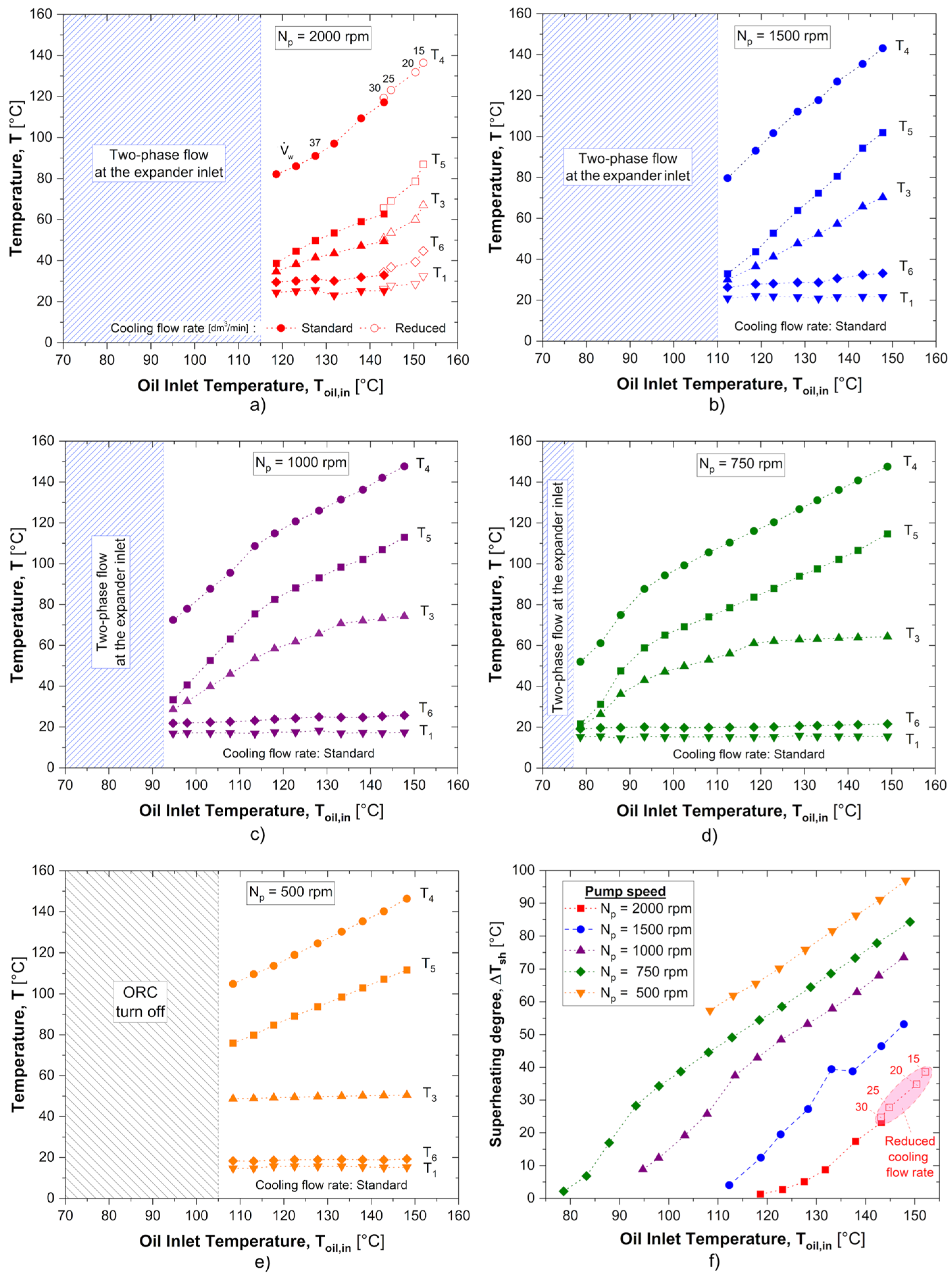
3.1. Micro-ORC Operating Range

Figure 3 highlights the significant influence of the pump speed and thermal oil temperature at the evaporator inlet on the operating conditions of the investigated biomass-fired ORC unit. For this purpose, the plot shows the temperatures in the ORC key points (Figure 3a–e) and the superheating degree at the entrance of the expander (Figure 3f).
The investigation refers to pump rotational speed ( N p u m p ) ranging between 500 and 2000 rpm. The maximum temperature of the thermal oil is about 150 °C for all the analysed pump regimes (Table 6), depending on the maximum thermal level of the biomass boiler, while the minimum oil temperature is defined to prevent the presence of liquid at the entrance of the expander. Consequently, the thermal oil operating range reduces as the pump speed increases due to the progressive rise in the saturation pressure and temperature at the expander inlet. The blue hatched area in Figure 3 illustrates the region where two-phase flow at the expander entrance occurs, producing irregular working conditions and potential erosion problems [64,74,75]. At N p u m p = 2000 rpm (Figure 3a), the thermal oil temperature ( T o i l , i n ) ranges between about 119 and 150 °C, and the highest thermal levels are possible by reducing the cooling water flow rate from the standard operating conditions (hollow symbols in Figure 3a) owing to the boiler’s maximum thermal power.
The investigated recuperative ORC exhibits the most extended operating range at N p u m p = 750 rpm (Figure 3d), with T o i l , i n moving between 78.6 and 149 °C.
When the pump speed reduces to 500 rpm (Figure 3e), the system power decreases significantly, and the biomass-fired ORC does not work for oil temperatures lower than 108.4 °C (grey hatched area).
Furthermore, Figure 3 shows that the temperatures of the organic fluid at the expander inlet ( T 4 ) and outlet ( T 5 ) rise noticeably with the thermal oil temperature for all the investigated pump rotational speeds, while the temperatures at the entrance of the condenser ( T 6 ) and pump ( T 1 ) exhibit variations always lower than five degrees Celsius.
The evaporator inlet temperature ( T 3 ) strongly depends on the pump speed. At the highest regimes (2000 and 1500 rpm, Figure 3a and Figure 3b, respectively), the oil temperature rise produces a significant increase in T 3 . Conversely, at minimum pump rotational speed (500 rpm, Figure 3e), the organic fluid reaches saturated conditions in the regenerator, and the temperature presents a slight rise with the oil temperature, as already observed for points 1 and 6. At intermediate pump regimes (1000 and 750 rpm, Figure 3c and Figure 3d, respectively), the evaporator inlet temperature upsurges rapidly until the saturation levels for the high temperatures of the hot source occur. In these conditions, the influence of the oil thermal level reduces noticeably.
As the pump speed decreases, the evaporation pressure reduces. Consequently, the superheating degree rises for a fixed temperature of the thermal oil (Figure 3f). The highest value is about 97 °C at 500 rpm, while the superheating degrees are always lower than 24 °C for N p u m p = 2000 rpm. Figure 4a illustrates the influence of the pump speed and thermal oil temperature on the pressure at the entrance of the expander ( p 4 ) and pump ( p 1 ). While p 1 pressure rises slightly with the pump speed, it nearly stays constant when the oil temperature varies. On the other hand, the pressure at the expander entrance increases with the growth in oil thermal level for all the investigated conditions, and this effect amplifies as the pump rotational regime increases. At 500 rpm, the pressure upsurge at the expander entrance is about 0.1 bar when the oil temperature moves from 118 to 143 °C, and the corresponding pressure rise reaches 3 bar at 2000 rpm.
The decrease in the cooling flow rate produces a further pressure increase in the ORC working fluid both at the entrance of the expander and pump due to the rise in the thermal (and pressure) levels within the condenser. In particular, the maximum pressure at the expander and pump inlet is 12.0 and 2.5 bar, respectively, at a 15 L/min coolant flow rate.
It is worth noticing that the pressure difference between the entrances of the two machines ( Δ p ) can be expressed as a function of the expander inlet pressure, as shown in Figure 4b. A linear trend appears when the coolant mass flow rate is around the typical value (37 L/min), as follows:
p = p 4 p 1 = α ·   p 4 + β
where α = 0.9273 and β = −0.8316, with R2 = 0.9992. The previous rule is not suitable when the volumetric flow rate of the cooling water is lower than 25 L/min due to the higher increase in the pressure at the pump inlet and the consequent decrease in the pressure difference.

3.2. Influence of Operating Conditions on ORC Global Performance

This section investigates the behaviour of the main components of the biomass regenerative micro-ORC (e.g., pump, evaporator, and expander) and the system’s global performance (e.g., electric power and efficiency) as a function of the operating conditions.
Figure 5 shows the influence of pump rotational speeds and thermal oil temperatures on the evaporator’s thermal power. The higher the pump regime and input thermal level, the higher the evaporator power. In particular, the experimental analysis highlights a significant increase with the pump speed. The maximum values are around 29 kW when the pump speed is 2000 rpm, and the thermal oil temperatures are higher than 140 °C. In these conditions, the coolant flow rate exerts a negligible effect on the evaporator power. The minimum value is 8.1 kW when the pump speed reduces to 500 rpm, and the thermal oil temperature is lower than 110 °C. For similar thermal oil temperatures, the evaporator power reaches about 11 kW and 15 kW at 750 and 1000 rpm, respectively.
The expander electric power output exhibits a near-linear increase with the pressure difference Δ p (Figure 6). The electric power ranges between 0.44 kW and 2.57 kW, with pump speeds equal to 500 and 2000 rpm, respectively. A wider power variation is observed for higher pressure drops, whereas the growth is rather modest when the pressure difference rises more gradually, as is evident for pump speeds N p u m p ≤ 1000 rpm. Furthermore, at the same pressure drop, slower pump speeds and, as a consequence, higher superheating degrees have higher expander electric power. For instance, the electric power at N p u m p = 1500 rpm is about 200 W higher than the corresponding values registered at the maximum pump speed when the pressure difference Δ p ranges between 6.5 and 8.5 bar.
Figure 7 illustrates the back work ratio ( B W R ) as a function of the expander electric power for the investigated operating conditions. The figure highlights the importance of optimising pump operation to balance electric power generation and pump energy consumption, particularly at high and mid-range speeds, where the B W R can significantly impact overall system efficiency. At a fixed rotational speed of the pump, the dimensionless parameter shows an increasing pump impact as the electric expander power decreases. The pump electric request maintains similar values when the change in the expander power is low due to the limited increase in the pressure difference, as highlighted in Figure 4b. At N p u m p = 500 rpm, the electric pump power is close to 20 W for all the investigated conditions, with B W R ranging from 4.5% to 3.6%. At N p u m p = 750 rpm, the pump power is around 50 W, excluding the point with the lowest expander production ( B W R = 8.3%), where the electric absorption reaches approximately 40 W, and similar behaviour is also registered at 1000 rpm, where the pump power settles at about 70 W, excepting the two lowest expander powers. The B W R index varies between 10.4% and 7.4% at 1500 rpm, with electric pump power demand ranging between 130 W and 180 W. The highest electric requests and B W R values (250 W and 13.0%, respectively) are at the maximum pump rotational speed.
Figure 8a confirms the linear trend of the net electric power of the micro-scale ORC apparatus as a function of the pressure difference Δ p . The highest value (2.30 kW) is at the maximum pump speed (2000 rpm) and the minimum cooling flow rate (15 L/min). The decrease in the pump rotational regime produces a drop in the pressure difference and, consequently, a reduction in the net electric power. At 500 rpm pump speed, the ORC net electric power ranges between 400 W and 550 W, with pressure differences around 2 bar. Furthermore, Figure 8b demonstrates that the ORC net electric power increases with the superheating degree at the expander entrance for fixed pump speed.
The effect is significant for Δ T s h lower than 20 °C and reduces progressively for values higher than 40 °C.
The influence of the superheating degree at the entrance of the expander ( Δ T s h ) on net electric efficiency for the different pump regimes is visible in Figure 9a. It is interesting to notice that a single curve correlates all the experimental data if plotted as the normalised electric efficiency ( η ¯ e l ) as a function of the superheating degree:
η ¯ e l = η e l , N η e l   m a x , N = f Δ T s h
where η e l , N is the generic electric efficiency at the pump speed N , and η e l   m a x , N represents the corresponding maximum electric efficiency at the same pump speed N . Figure 9b highlights that, independent of the pump rotational speed, the normalised electric efficiency tends to distribute along the same exponential curve, whose functional form is
η ¯ e l = a b ·   c   Δ T s h
where a = 0.98249, b = 0.48577, and c = 0.94265, with R2 = 0.9542.
This finding offers significant advantages, enabling a substantial decrease in the measurements required to characterise ORC behaviour across varying operating conditions and significantly reducing the time and cost associated with experimental investigations. Furthermore, plotting the experimental data according to the proposed method facilitates real-time data validation during measurement processes. The presented result can serve as a valuable resource for predicting the performance of other micro-ORC units under varying superheating conditions. This information can facilitate comparative studies between different system designs and aid in developing efficient and optimised micro-ORC systems.
The electric efficiency increases until reaching a plateau for Δ T s h around 40 °C, above which it remains almost constant for all the investigated operating conditions. The rapid growth in electric efficiency for low superheating degrees occurs when the pressure increases significantly at the expander inlet (Figure 9c). Conversely, for high superheating degrees, the pressure increase shows small increments, and this leads to almost constant electric efficiency due to the limited rise in expander electric power and a proportional growth in the thermal power input. For this purpose, Figure 9d highlights the influence of the thermal input of the evaporator on the net electric efficiency. The micro-ORC efficiency ranges from 4.3% to 8.5% for the investigated operating conditions. In particular, the maximum value is achieved for 1000 rpm of pump speed, whereas further increases in pump speed do not lead to any significant enhancements. The figure demonstrates that a narrow range of oil thermal power exists for each pump regime and tends to become smaller as the pump speed decreases. The system guarantees an efficiency of about 5.5% for low oil thermal power between 8 kW and 10 kW, whereas the maximum electric efficiency is obtained for thermal input higher than 16 kW.

3.3. Suggested Configurations

The performance of the biomass micro-scale recuperative ORC unit, encompassing net electric efficiency and power, is summarised in Figure 10. As already observed, the highest electric power (2.30 kW) is at the maximum pump speed (2000 rpm). In these conditions, the net electric efficiency reaches 7.94% with a thermal power equal to 28.91 kW. On the other hand, the highest efficiency is 8.55% at 1000 rpm pump speed. The corresponding net electric power and evaporator thermal input reduce to 1.38 kW and 16.10 kW, respectively. Experimental data suggest adopting the highest pump speed and evaporator power to maximise the ORC net electric power, while low pump speeds are most suitable when the ORC electric power is defined owing to the higher efficiency. For instance, when the net electric request is about 1.4 kW, electric efficiency moves from 5.3% to 8.4%, reducing the pump rotational regime from 2000 to 1000 rpm. Similarly, at 2.0 kW ORC electric power, net efficiency passes from about 5.0% to 7.0%, decreasing the pump speed from 2000 to 1500 rpm.
The minimum distance criterion can be adopted to define the proper trade-off between maximum electric efficiency (ME) and maximum electric power (MP) conditions. The methodology suggests selecting the ORC operating state that guarantees the minimum dimensionless distance to the ideal point that presents the highest electric power and efficiency values, according to the following equation [76,77]:
d = min   P e l , i P e l , m i n P e l , m a x P e l , m i n 2 + η e l , i η e l , m i n η e l , m a x η e l , m i n 2
The subscript i corresponds to the generic operating condition with net electric power P e l , i and efficiency η e l , i , whereas subscripts m a x and m i n refer to the maximum and minimum values, respectively.
The methodology recommends adopting a 1500 rpm pump speed and 24.75 kW evaporator power to balance the two priorities. The corresponding net electric power and efficiency are 2.09 kW and 8.46%, respectively. The main performance and operating conditions are in Table 9, which also illustrates the equivalent parameters for the configurations achieving the highest power (MP) or efficiency (ME). The adoption of the suggested configuration highlights a 0.9% decrease in efficiency compared to the corresponding value of the ME operating condition, but the rise in power reaches 44.8%. Furthermore, the comparison with the highest power point shows an 8.7% drop for the suggested setup with a 6.6% increase in the electric efficiency, confirming that the selected operating condition represents a suitable trade-off to balance maximum electric performance.
The experimental analysis demonstrates that the investigated biomass-fired recuperative ORC offers good performance in a wide range of operating conditions and represents a possible option for micro-scale applications in the domestic and third sectors, and is able to promote a sustainable and efficient transition towards decentralised power production based on renewable sources, aligning with the Sustainable Development Goal on affordable and clean energy at the local level. For this purpose, selecting the proper operating conditions (e.g., pump speed and thermal source temperature) is fundamental to reaching maximum performance in design and off-design conditions.

4. Conclusions

This work experimentally investigated the energy performance of a biomass-fired recuperative ORC system for micro-scale applications under both design and off-design conditions across a wide operating range, addressing the limited data available in the literature.
The most relevant findings can be summarised as follows:
  • Key parameters affecting the ORC performance include pump speed, thermal oil temperature, and the superheating degree at the entrance of the expander.
  • The micro-scale unit demonstrates flexibility in operation, achieving a maximum net electric power of 2.30 kW at the highest pump speed (2000 rpm) and a thermal oil temperature of 152.2 °C. Conversely, the minimum electric power is 0.42 kW at a thermal oil temperature of 113.2 °C and a pump speed of 500 rpm.
  • The investigated biomass-fired recuperative ORC achieves a maximum electric efficiency of 8.55% with a pump speed of 1000 rpm. In this condition, the net power output and thermal oil temperature are 1.37 kW and 133.2 °C, respectively.
  • The system effectiveness increases with increasing superheating degree, plateauing above approximately 40 °C. While pump speed also influences efficiency, above 1000 rpm, performance depends primarily on superheating degree.
  • A single exponential curve correlates all the experimental data if plotted as the normalised electric efficiency as a function of the superheating degree at the entrance of the expander. This result highlights the potential of using a normalised curve to predict the performance of different micro-ORC systems, significantly reducing the time and cost associated with experimental investigations and facilitating real-time data validation during measurement campaigns.
  • A strategy to maximise ORC performance involves adjusting the pump speed to ensure adequate superheating of the working fluid according to the available thermal power.
  • The experimental investigation conducted illustrates that the analysed biomass recuperative ORC could represent a viable option for micro-scale applications. The system exhibits robust performance across a broad spectrum of operating conditions and could contribute to a sustainable shift towards effective decentralised renewable energy production and the achievement of UN Sustainable Development Goals for affordable and clean energy.

Author Contributions

Conceptualization, A.A. and L.F.; methodology, A.A. and L.F.; software, L.F. and D.P.; validation, A.A., L.F. and P.M.; formal analysis, A.A., D.P., L.F. and P.M.; investigation, A.A. and L.F.; resources, A.A.; data curation, L.F. and D.P.; writing—original draft preparation, A.A. and L.F.; writing—review and editing, A.A., L.F. and P.M.; visualisation, A.A. and L.F.; supervision, A.A.; project administration, A.A.; funding acquisition, A.A. All authors have read and agreed to the published version of the manuscript.

Funding

This research was funded by the Next Generation EU—Italian National Recovery and Resilience Plan (NRRP), Mission 4, Component 2, Investment 1.5, call for the creation and strengthening of “Innovation Ecosystems”, building “Territorial R&D Leaders” (Directorial Decree n. 2021/3277)—project “Tech4You—Technologies for climate change adaptation and quality of life improvement” n. ECS0000009 (CUP H23C22000370006).

Data Availability Statement

Data will be made available on request.

Conflicts of Interest

The authors declare no conflicts of interest.

Nomenclature

Acronyms
EUEuropean Union
GHGGreenhouse gas
GWPGlobal warming potential
IHEInternal heat exchanger
MEMaximum efficiency
MPMaximum power
ODPOzone depletion potential
PHEXPlate heat exchanger
SDGsSustainable development goals
Symbols
a Correlation coefficient [-]
α Correlation coefficient [-]
b Correlation coefficient [-]
β Correlation coefficient [bar]
B W R Back work ratio [%]
c Correlation coefficient [-]
c p Specific heat capacity [J/(kg K)]
d Dimensionless minimum distance [-]
δ F Overall uncertainty on the generic quantity F [-]
Δ p Pressure difference [bar]
Δ T s h Superheating degree [°C]
e Uncertainty of the generic measurement x i [%]
F Generic quantity [-]
F % Relative uncertainty [%]
m ˙ Mass flow rate [kg/s]
N Rotational speed [rpm]
η Efficiency [-]
η ¯ e l Normalised electric efficiency [-]
P Power [W]
p Pressure [Pa]
Q ˙ Thermal power [W]
T Temperature [°C]
V ˙ Volumetric flow rate [m3/s]
Subscripts
a b Auxiliary boiler
c o n d Condenser
e l Electric
e v a p Evaporator
e x p Expander
i Generic operating condition
i n Inlet
m a x Maximum
m i n Minimum
n e t Net power
o i l Thermal oil
o u t Outlet
p u m p Pump
s h Superheating
t h Thermal
w Water

References

  1. United Nations Environment Programme. Emissions Gap Report 2023: Broken Record—Temperatures Hit New Highs, yet World Fails to Cut Emissions (Again); United Nations Environment Programme: Nairobi, Kenya, 2023; ISBN 978-92-807-4098-1. [Google Scholar]
  2. COP28; IRENA; GRA. Tripling Renewable Power and Doubling Energy Efficiency by 2030 Crucial Steps Towards 1.5 °C; International Renewable Energy Agency: Abu Dhabi, United Arab Emirates, 2023; ISBN 978-1-5231-5736-5. [Google Scholar]
  3. Gonidaki, D.; Bellos, E. A Detailed Review of Organic Rankine Cycles Driven by Combined Heat Sources. Energies 2025, 18, 526. [Google Scholar] [CrossRef]
  4. Evro, S.; Oni, B.A.; Tomomewo, O.S. Global Strategies for a Low-Carbon Future: Lessons from the US, China, and EU’s Pursuit of Carbon Neutrality. J. Clean. Prod. 2024, 461, 142635. [Google Scholar] [CrossRef]
  5. United Nations. Paris Agreement; United Nations: New York City, NY, USA, 2015. [Google Scholar]
  6. United Nations. Sustainable Development Goals. Available online: https://sdgs.un.org/goals (accessed on 16 December 2024).
  7. Okunevičiūtė Neverauskienė, L.; Dirma, V.; Tvaronavičienė, M.; Danilevičienė, I. Assessing the Role of Renewable Energy in the Sustainable Economic Growth of the European Union. Energies 2025, 18, 760. [Google Scholar] [CrossRef]
  8. Nagaj, R.; Gajdzik, B.; Wolniak, R.; Grebski, W.W. The Impact of Deep Decarbonization Policy on the Level of Greenhouse Gas Emissions in the European Union. Energies 2024, 17, 1245. [Google Scholar] [CrossRef]
  9. European Council. Fit to 55. Available online: https://www.consilium.europa.eu/en/policies/green-deal/fit-for-55-the-eu-plan-for-a-green-transition/ (accessed on 16 December 2024).
  10. European Commission. The European Green Deal. Available online: https://commission.europa.eu/strategy-and-policy/priorities-2019-2024/european-green-deal_en (accessed on 16 December 2024).
  11. European Parliament and Council Directive (EU). 2023/2413 of the European Parliament and of the Council of 18 October 2023 Amending Directive (EU) 2018/2001, Regulation (EU) 2018/1999 and Directive 98/70/EC as Regards the Promotion of Energy from Renewable Sources, and Repealing Council Directive (EU) 2015/652; European Parliament and Council Directive (EU): Luxembourg, 2023. [Google Scholar]
  12. European Parliament and Council Directive (EU). 2023/1791 of the European Parliament and of the Council of 13 September 2023 on Energy Efficiency and Amending Regulation (EU) 2023/955 (Recast); European Parliament and Council Directive (EU): Luxembourg, 2023. [Google Scholar]
  13. Pylak, K.; Pizoń, J.; Łazuka, E. Evolution of Regional Innovation Strategies Towards the Transition to Green Energy in Europe 2014–2027. Energies 2024, 17, 5669. [Google Scholar] [CrossRef]
  14. Lu, P.; Liang, Z.; Luo, X.; Xia, Y.; Wang, J.; Chen, K.; Liang, Y.; Chen, J.; Yang, Z.; He, J.; et al. Design and Optimization of Organic Rankine Cycle Based on Heat Transfer Enhancement and Novel Heat Exchanger: A Review. Energies 2023, 16, 1380. [Google Scholar] [CrossRef]
  15. Corigliano, O.; Algieri, A.; Fragiacomo, P. Turning Data Center Waste Heat into Energy: A Guide to Organic Rankine Cycle System Design and Performance Evaluation. Appl. Sci. 2024, 14, 6046. [Google Scholar] [CrossRef]
  16. Shah Irshad, A.; Naseer Zakir, M.; Shah Rashad, S.; Elsayed Lotfy, M.; Mikhaylov, A.; Elkholy, M.H.; Pinter, G.; Senjyu, T. Comparative Analyses and Optimizations of Hybrid Biomass and Solar Energy Systems Based upon a Variety of Biomass Technologies. Energy Convers. Manag. X 2024, 23, 100640. [Google Scholar] [CrossRef]
  17. Cao, J.; Zheng, L.; Zheng, Z.; Peng, J.; Hu, M.; Wang, Q.; Leung, M.K.H. Recent Progress in Organic Rankine Cycle Targeting Utilisation of Ultra-Low-Temperature Heat towards Carbon Neutrality. Appl. Therm. Eng. 2023, 231, 120903. [Google Scholar] [CrossRef]
  18. Falbo, L.; Perrone, D.; Morrone, P.; Algieri, A. Integration of Biodiesel Internal Combustion Engines and Transcritical Organic Rankine Cycles for waste-heat Recovery in small-scale Applications. Int. J. Energy Res. 2022, 46, 5235–5249. [Google Scholar] [CrossRef]
  19. Heidarnejad, P.; Genceli, H.; Hashemian, N.; Asker, M.; Al-Rawi, M. Biomass-Fueled Organic Rankine Cycles: State of the Art and Future Trends. Energies 2024, 17, 3788. [Google Scholar] [CrossRef]
  20. Wieland, C.; Schifflechner, C.; Dawo, F.; Astolfi, M. The Organic Rankine Cycle Power Systems Market: Recent Developments and Future Perspectives. Appl. Therm. Eng. 2023, 224, 119980. [Google Scholar] [CrossRef]
  21. Market Research Future Organic Rankine Cycle Market Research Report. Available online: https://www.marketresearchfuture.com/reports/organic-rankine-cycle-market-22975 (accessed on 16 April 2025).
  22. Wieland, C.; Schifflechner, C.; Braimakis, K.; Kaufmann, F.; Dawo, F.; Karellas, S.; Besagni, G.; Markides, C.N. Innovations for Organic Rankine Cycle Power Systems: Current Trends and Future Perspectives. Appl. Therm. Eng. 2023, 225, 120201. [Google Scholar] [CrossRef]
  23. Mascuch, J.; Novotny, V.; Spale, J.; Vodicka, V.; Zeleny, Z. Experience from Set-up and Pilot Operation of an in-House Developed Biomass-Fired ORC Microcogeneration Unit. Renew. Energy 2021, 165, 251–260. [Google Scholar] [CrossRef]
  24. Feng, Y.; Liang, H.; Xu, K.; Wang, Y.; Lu, Y.; Lin, C.-H.; Hung, T.-C. Experimental Study on the Performance of a Great Progress 10 kW Organic Rankine Cycle for Low-Grade Heat Source Based on Scroll-Type Expander. Energy 2023, 284, 128627. [Google Scholar] [CrossRef]
  25. Carraro, G.; Bori, V.; Lazzaretto, A.; Toniato, G.; Danieli, P. Experimental Investigation of an Innovative Biomass-Fired Micro-ORC System for Cogeneration Applications. Renew. Energy 2020, 161, 1226–1243. [Google Scholar] [CrossRef]
  26. Naseri, A.; Moradi, R.; Norris, S.; Subiantoro, A. Experimental Investigation of a Revolving Vane Expander in a Micro-Scale Organic Rankine Cycle System for Low-Grade Waste Heat Recovery. Energy 2022, 253, 124174. [Google Scholar] [CrossRef]
  27. Kaczmarczyk, T.Z.; Żywica, G.; Ihnatowicz, E. Experimental Research on Scroll Expanders Operating in Parallel in an Organic Rankine Cycle System with a Biomass Boiler. Energy Convers. Manag. 2020, 224, 113390. [Google Scholar] [CrossRef]
  28. Wu, T.; Cai, S.; Yao, Z.; Yin, X.; Ma, X.; Gao, X.; Xie, F.; Yang, H.; Shen, X.; Shao, L. Design and Optimization of the Radial Inflow Turbogenerator for Organic Rankine Cycle System Based on the Genetic Algorithm. Appl. Therm. Eng. 2024, 253, 123749. [Google Scholar] [CrossRef]
  29. Spale, J.; Jun, G.C.; Novotny, V.; Streit, P.; Weiß, A.P.; Kolovratnik, M. Development of a 10 kW Class Axial Impulse Single Stage Turboexpander for a Micro-CHP ORC Unit. EPJ Web Conf. 2022, 264, 01044. [Google Scholar] [CrossRef]
  30. Villarino, Y.T.; Rial, L.P.; Rodríguez-Abalde, Á. Assessment of a Residual Biomass Micro-Combined Heat and Power System Based on an Organic Rankine Cycle Coupled to a Boiler. J. Environ. Manag. 2022, 301, 113832. [Google Scholar] [CrossRef] [PubMed]
  31. Perrone, D.; Falbo, L.; Morrone, P.; Algieri, A. Techno-Economic Investigation of Integrated Biodiesel Internal Combustion Engines and Transcritical Organic Rankine Cycles for Small-Scale Combined Heat and Power Generation. Energy Convers. Manag. X 2023, 20, 100426. [Google Scholar] [CrossRef]
  32. Feng, Y.; Xu, K.; Zhang, Q.; Hung, T.-C.; He, Z.; Xi, H.; Rasheed, N. Experimental Investigation and Machine Learning Optimization of a Small-Scale Organic Rankine Cycle. Appl. Therm. Eng. 2023, 224, 120120. [Google Scholar] [CrossRef]
  33. Zhang, Y.; Tsai, Y.-C.; Ren, X.; Tuo, Z.; Wang, W.; Gong, L.; Hung, T.-C. Experimental Study of the External Load Characteristics on a Micro-Scale Organic Rankine Cycle System. Energy 2024, 306, 132453. [Google Scholar] [CrossRef]
  34. Mascuch, J.; Novotny, V.; Vodicka, V.; Spale, J.; Zeleny, Z. Experimental Development of a Kilowatt-Scale Biomass Fired Micro—CHP Unit Based on ORC with Rotary Vane Expander. Renew. Energy 2020, 147, 2882–2895. [Google Scholar] [CrossRef]
  35. Liu, C.; Wang, S.; Zhang, C.; Li, Q.; Xu, X.; Huo, E. Experimental Study of Micro-Scale Organic Rankine Cycle System Based on Scroll Expander. Energy 2019, 188, 115930. [Google Scholar] [CrossRef]
  36. Qiu, K.; Entchev, E. A Micro-CHP System with Organic Rankine Cycle Using R1223zd(E) and n-Pentane as Working Fluids. Energy 2022, 239, 121826. [Google Scholar] [CrossRef]
  37. Wang, Z.; Pan, H.; Xia, X.; Xie, B.; Peng, D.; Yang, H. Experimental Investigation on Steady and Dynamic Performance of Organic Rankine Cycle with R245fa/R141b under Different Cooling and Expander Speed Conditions. Energy 2022, 241, 122511. [Google Scholar] [CrossRef]
  38. Wang, Z.; Zhao, Y.; Xia, X.; Pan, H.; Zhang, S.; Liu, Z. Experimental Evaluation of Organic Rankine Cycle Using Zeotropic Mixture under Different Operation Conditions. Energy 2023, 264, 126188. [Google Scholar] [CrossRef]
  39. Zhang, H.-H.; Zhang, Y.-F.; Feng, Y.-Q.; Chang, J.-C.; Chang, C.-W.; Xi, H.; Gong, L.; Hung, T.-C.; Li, M.-J. The Parametric Analysis on the System Behaviors with Scroll Expanders Employed in the ORC System: An Experimental Comparison. Energy 2023, 268, 126713. [Google Scholar] [CrossRef]
  40. Luo, J.; Lu, P.; Chen, K.; Luo, X.; Chen, J.; Liang, Y.; Yang, Z.; Chen, Y. Experimental and Simulation Investigation on the Heat Exchangers in an ORC under Various Heat Source/Sink Conditions. Energy 2023, 264, 126189. [Google Scholar] [CrossRef]
  41. Fatigati, F.; Vittorini, D.; Cipollone, R. Dynamic Response of a Micro-Scale ORC-Based Power Unit Fed by Solar Flat Panels. Appl. Therm. Eng. 2024, 243, 122546. [Google Scholar] [CrossRef]
  42. Eyerer, S.; Dawo, F.; Schifflechner, C.; Niederdränk, A.; Spliethoff, H.; Wieland, C. Experimental Evaluation of an ORC-CHP Architecture Based on Regenerative Preheating for Geothermal Applications. Appl. Energy 2022, 315, 119057. [Google Scholar] [CrossRef]
  43. Agung Pambudi, N.; Wibowo, S.; Ranto; Huat Saw, L. Experimental Investigation of Organic Rankine Cycle (ORC) for Low Temperature Geothermal Fluid: Effect of Pump Rotation and R-134 Working Fluid in Scroll-Expander. Energy Eng. 2021, 118, 1565–1576. [Google Scholar] [CrossRef]
  44. Spale, J.; Vodicka, V.; Zeleny, Z.; Pavlicko, J.; Mascuch, J.; Novotny, V. Scaling up a Woodchip-Fired Containerized CHP ORC Unit toward Commercialization. Renew. Energy 2022, 199, 1226–1236. [Google Scholar] [CrossRef]
  45. European Commission; Joint Research Centre. The Use of Woody Biomass for Energy Production in the EU; Publications Office: Luxembourg, 2021. [Google Scholar]
  46. Backa, A.; Čajová Kantová, N.; Nosek, R.; Patsch, M. Evaluating the Combustion of Various Biomass Pellets in a Small Heat Source with Underfeed Pellet Burner: Heat Output, Gas Emission and Ash Melting Behavior. J. Energy Inst. 2025, 118, 101936. [Google Scholar] [CrossRef]
  47. Asif, Z.; Chen, Z.; Wang, H.; Zhu, Y. Update on Air Pollution Control Strategies for Coal-Fired Power Plants. Clean Technol. Environ. Policy 2022, 24, 2329–2347. [Google Scholar] [CrossRef]
  48. Tran, H.; Juno, E.; Arunachalam, S. Emissions of Wood Pelletization and Bioenergy Use in the United States. Renew. Energy 2023, 219, 119536. [Google Scholar] [CrossRef]
  49. Morrone, P.; Amelio, M.; Algieri, A.; Perrone, D. Hybrid Biomass and Natural Gas Combined Cycles: Energy Analysis and Comparison between Different Plant Configurations. Energy Convers. Manag. 2022, 267, 115874. [Google Scholar] [CrossRef]
  50. Zygmunt Kaczmarczyk, T. Experimental Research of a Small Biomass Organic Rankine Cycle Plant with Multiple Scroll Expanders Intended for Domestic Use. Energy Convers. Manag. 2021, 244, 114437. [Google Scholar] [CrossRef]
  51. Zhang, Q.; Feng, Y.-Q.; Xu, K.-J.; Liang, H.-J.; Liu, Z.-N.; Zhao, C.-Y.; Wang, Y.-Z.; Sapin, P.; Markides, C.N. Dynamic Behaviour and Performance Evaluation of a Biomass-Fired Organic Rankine Cycle Combined Heat and Power (ORC-CHP) System under Different Control Strategies. Appl. Therm. Eng. 2024, 248, 123236. [Google Scholar] [CrossRef]
  52. Douvartzides, S.; Tsiolikas, A.; Charisiou, N.; Souliotis, M.; Karayannis, V.; Taousanidis, N. Energy and Exergy-Based Screening of Various Refrigerants, Hydrocarbons and Siloxanes for the Optimization of Biomass Boiler–Organic Rankine Cycle (BB–ORC) Heat and Power Cogeneration Plants. Energies 2022, 15, 5513. [Google Scholar] [CrossRef]
  53. Mota-Babiloni, A.; Amat-Albuixech, M.; Molés-Ribera, F.; Navarro-Esbrí, J. Techno-Economic Feasibility of Organic Rankine Cycles (ORC) for Waste Heat Recovery. In Heat Energy Recovery for Industrial Processes and Wastes; Borge-Diez, D., Rosales-Asensio, E., Eds.; Green Energy and Technology; Springer International Publishing: Cham, Switzerland, 2023; pp. 105–137. ISBN 978-3-031-24373-8. [Google Scholar]
  54. Vilasboas, I.F.; Dos Santos, V.G.S.F.; Ribeiro, A.S.; Da Silva, J.A.M. Surrogate Models Applied to Optimized Organic Rankine Cycles. Energies 2021, 14, 8456. [Google Scholar] [CrossRef]
  55. Damarseckin, S.; Junior Kane, S.Y.; Atiz, A.; Karakilcik, M.; Sogukpinar, H.; Bozkurt, I.; Oyucu, S.; Aksoz, A. A Comparative Review of ORC and R-ORC Technologies in Terms of Energy, Exergy, and Economic Performance. Heliyon 2024, 10, e40575. [Google Scholar] [CrossRef]
  56. Qiu, G.; Shao, Y.; Li, J.; Liu, H.; Riffat, S.B. Experimental Investigation of a Biomass-Fired ORC-Based Micro-CHP for Domestic Applications. Fuel 2012, 96, 374–382. [Google Scholar] [CrossRef]
  57. Kaczmarczyk, T.Z.; Żywica, G.; Ihnatowicz, E. Experimental Study of a Low-Temperature Micro-Scale Organic Rankine Cycle System with the Multi-Stage Radial-Flow Turbine for Domestic Applications. Energy Convers. Manag. 2019, 199, 111941. [Google Scholar] [CrossRef]
  58. Mascuch, J.; Novotny, V.; Vodicka, V.; Zeleny, Z. Towards Development of 1–10 kW Pilot ORC Units Operating with Hexamethyldisiloxane and Using Rotary Vane Expander. Energy Procedia 2017, 129, 826–833. [Google Scholar] [CrossRef]
  59. Feng, Y.-Q.; Wu, Y.-Z.; Zhang, Q.; Liu, Z.-N.; Wang, X.-X.; Hung, T.-C.; Yu, H.-S.; He, Z.-X. Experiment Investigation and Machine Learning Prediction of a Biomass-Fired Organic Rankine Cycle Combined Heating and Power System under Various Heat Source Temperatures and Mass Flow Rates. Energy 2025, 324, 135841. [Google Scholar] [CrossRef]
  60. Moradi, R.; Cioccolanti, L. Modelling Approaches of Micro and Small-Scale Organic Rankine Cycle Systems: A Critical Review. Appl. Therm. Eng. 2024, 236, 121505. [Google Scholar] [CrossRef]
  61. Widianti, T.; Firdaus, H. A Decade of Organic Rankine Cycle Research Trends and Evolution: A Bibliometric Analysis. Evergreen 2024, 11, 2479–2503. [Google Scholar] [CrossRef]
  62. Jiménez-García, J.C.; Ruiz, A.; Pacheco-Reyes, A.; Rivera, W. A Comprehensive Review of Organic Rankine Cycles. Processes 2023, 11, 1982. [Google Scholar] [CrossRef]
  63. Fatigati, F.; Cipollone, R. The Benefits of a Recuperative Layout of an ORC-Based Unit Fed by a Solar-Assisted Reservoir Operating as a Micro-Cogeneration Plant. Energy Convers. Manag. 2024, 300, 117888. [Google Scholar] [CrossRef]
  64. Kaczmarczyk, T.Z.; Żywica, G. Experimental Study of the Effect of Load and Rotational Speed on the Electrical Power of a High-Speed ORC Microturbogenerator. Appl. Therm. Eng. 2024, 238, 122012. [Google Scholar] [CrossRef]
  65. Woodco. E-Compact Prestige 25P/40P; Installation and Operation Manual; Woodco: Sydney, Australia, 2017. [Google Scholar]
  66. Therminol. Therminol SP Heat Transfer Fluid. Available online: https://www.therminol.com/product/71093454 (accessed on 16 December 2024).
  67. Ji, D.; Cai, H.; Ye, Z.; Luo, D.; Wu, G.; Romagnoli, A. Comparison between Thermoelectric Generator and Organic Rankine Cycle for Low to Medium Temperature Heat Source: A Techno-Economic Analysis. Sustain. Energy Technol. Assess. 2023, 55, 102914. [Google Scholar] [CrossRef]
  68. Mana, A.A.; Kaitouni, S.I.; Kousksou, T.; Jamil, A. Enhancing Sustainable Energy Conversion: Comparative Study of Superheated and Recuperative ORC Systems for Waste Heat Recovery and Geothermal Applications, with Focus on 4E Performance. Energy 2023, 284, 128654. [Google Scholar] [CrossRef]
  69. Sim, J.-B.; Yook, S.-J.; Kim, Y.W. Development of 180 kW Organic Rankine Cycle (ORC) with a High-Efficiency Two-Stage Axial Turbine. Energies 2023, 16, 7112. [Google Scholar] [CrossRef]
  70. Moradi, R.; Villarini, M.; Cioccolanti, L. Experimental Modeling of a Lubricated, Open Drive Scroll Expander for Micro-Scale Organic Rankine Cycle Systems. Appl. Therm. Eng. 2021, 190, 116784. [Google Scholar] [CrossRef]
  71. Abbas, W.K.A.; Baumhögger, E.; Vrabec, J. Experimental Investigation of Organic Rankine Cycle Performance Using Alkanes or Hexamethyldisiloxane as a Working Fluid. Energy Convers. Manag. X 2022, 15, 100244. [Google Scholar] [CrossRef]
  72. Algieri, A.; Bova, S.; De Bartolo, C. Experimental and Numerical Investigation on the Effects of the Seeding Properties on LDA Measurements. J. Fluids Eng. 2005, 127, 514–522. [Google Scholar] [CrossRef]
  73. Doebelin, E.O. Measurement Systems: Application and Design, 5th ed.; McGraw-Hill Series in Mechanical Engineering; McGraw-Hill Higher Education: Boston, MA, USA, 2004; ISBN 978-0-07-119465-5. [Google Scholar]
  74. Li, Z.; Yu, X.; Wang, L.; Jiang, R.; Yu, X.; Huang, R.; Wu, J. Comparative Investigations on Dynamic Characteristics of Basic ORC and Cascaded LTES-ORC under Transient Heat Sources. Appl. Therm. Eng. 2022, 207, 118197. [Google Scholar] [CrossRef]
  75. Daniarta, S.; Nemś, M.; Kolasiński, P. A Review on Thermal Energy Storage Applicable for Low- and Medium-Temperature Organic Rankine Cycle. Energy 2023, 278, 127931. [Google Scholar] [CrossRef]
  76. Algieri, A.; Morrone, P. Thermo-Economic Investigation of Solar-Biomass Hybrid Cogeneration Systems Based on Small-Scale Transcritical Organic Rankine Cycles. Appl. Therm. Eng. 2022, 210, 118312. [Google Scholar] [CrossRef]
  77. Dincer, I.; Rosen, M.A.; Ahmadi, P. Optimization of Energy Systems, 1st ed.; Wiley: Hoboken, NJ, USA, 2017; ISBN 978-1-118-89443-9. [Google Scholar]
Figure 1. Simplified layout of the biomass-boiler micro-ORC system with the thermal oil circuit.
Energies 18 03201 g001
Figure 2. Layout of the recuperative micro-ORC unit (a); typical processes on the T-s diagram (b).
Energies 18 03201 g002
Figure 3. Influence of the thermal oil temperature and pump speed on the temperature at ORC key points: N p u m p = 2000 rpm (a), N p u m p = 1500 rpm (b), N p u m p = 1000 rpm (c), N p u m p = 750 rpm (d), N p u m p   = 500 rpm (e). Superheating degree at the expander inlet (f).
Energies 18 03201 g003
Figure 4. Influence of the thermal oil inlet temperature on the expander inlet pressure (a) and pressure ratio (b).
Energies 18 03201 g004
Figure 5. Effect of pump speed and thermal oil inlet temperature on evaporator thermal power.
Energies 18 03201 g005
Figure 6. Influence of the expander pressure difference on the expander electric power.
Energies 18 03201 g006
Figure 7. Back work ratio (BWR) as a function of the expander electric power.
Energies 18 03201 g007
Figure 8. Influence of the expander pressure difference (a) and superheating degree (b) on the ORC net electric power.
Energies 18 03201 g008
Figure 9. Effect of the superheating degree on the ORC net electric efficiency (a) and normalised ORC electric efficiency (b). Influence of the pressure difference (c) and evaporator thermal power (d) on the ORC electric efficiency.
Energies 18 03201 g009
Figure 10. Net electric power and efficiency of the investigated micro-scale ORC system.
Energies 18 03201 g010
Table 1. Experimental investigations into micro-scale biomass ORC. Main operating conditions and energy performance.
Electric PowerSystem
Configuration
Heat Transfer FluidHot Source
Temperature
Expander Inlet
Temperature
Thermal
Efficiency
Electric
Efficiency
[kW][-][-][°C][°C][%][%]
[50]0.03–1.2RecuperativeThermal oil179–204122–177-3.1–3.3
[25]1.0–2.1RecuperativeThermal oil130–155110–125-4.8–7.3
[30]1.5–3.6RecuperativeWater82–98--4.0–9.4 **
[56]0.82–0.86RecuperativeWater110–129≤126.6-1.3–1.4
[57]0.2–2.1 *RecuperativeThermal oil≤200≤1805.0–6.5-
[58]0.6–1.2RecuperativeThermal oil≤350≤210-2.8
[58]1.0SimpleFlue gas280–350155–166-4.2
[34]1.87SimpleFlue gas≤650≤192-2.5
[59]1.19–1.53 *SimpleWater110–130100–1159.5–12.1-
Note: * Expander electric power; ** unsteady conditions.
Table 2. Main characteristics of adopted wood pellets.
FeatureValue
Length3.15–40 mm
Diameter6 mm ± 1 mm
Lower heating value (LHV)16.3 ÷ 19.0 MJ/kg
Ash content<0.7%
Max sulphur content<0.03%
Max nitrogen content<0.3%
Max chlorine content<0.02%
Table 3. Main characteristics of the thermal oil.
Properties
Commercial nameTherminol SP
Composition Synthetic hydrocarbon mixture
AppearanceClear yellow liquid
Maximum bulk temperature315 °C
Normal boiling point 335 °C
Flash point177 °C
Autoignition temperature366 °C
Kinematic viscosity at 100 °C19 mm2/s
Pour point−40 °C
Mean molecular weight320
Density at 15 °C875 kg/m3
Maximum moisture content<150 ppm
Table 4. Main properties of the organic fluid R245fa.
PropertiesUnitValue
Name[-]R245fa
Normal boiling point [°C]15
Critical temperature [°C]154
Critical pressure [bar]36.5
Molar mass [kg/kmol]134
GWP[-]1030
ODP[-]0
Table 5. Main specifics of the heat exchangers.
PropertiesUnitEvaporatorIHECondenser
Hot side volume[dm3]2.661.892.62
Cold side volume[dm3]2.781.952.71
Number of plates[-]506266
Heat transfer surface[m2]2.471.692.42
Max working pressure[bar]362827
Width of plate heat exchanger[mm]119117119
Length of plate heat exchanger[mm]479234320
Gap between plates[mm]2.252.342.24
Port area[cm2]4.528.548.54
Plate thickness[mm]0.40.40.4
Chevron angle[°]606060
Material [-]Stainless steelStainless steelStainless steel
Table 6. Characteristics of measurement devices.
Meter TypePhysical Principle of Measurement Measuring RangeUncertainty
Energy meterPower meter0–5000 W1%
Oil flow meterVariable area flow meter100–1800 L/h1.5%
Water flow meterVortex9–150 L/min1 L/min
Temperature meterPT 1000−50–200 °C±0.9 °C
Temperature meterK-type thermocouples−40–1100 °C±1.5 °C
Pressure meterSealed gauge0–30 (abs)1.5%
Table 7. Main operating conditions during the experimental campaign.
Pump
Speed
Expander SpeedThermal Oil Inlet TemperatureThermal Oil Flow RateCooling Water Inlet TemperatureCooling Water Flow Rate
[rpm][rpm][°C][dm3/h][°C][dm3/min]
20002000118.6–143.210001537
15002000112.3–147.810001537
1000200094.7–147.810001537
750200078.6–149.010001537
5002000108.4–148.110001537
20002000141.6–152.210001515–30
Table 8. Relative uncertainties of the main ORC performance parameters.
ParameterRelative Uncertainty
Evaporator thermal power±2.6%
Condenser thermal power ±5.2%
Electric efficiency±2.8%
Back work ratio±1.9%
Table 9. Main performance and operating conditions of the micro-scale ORC system. Comparison between maximum power (MP), maximum efficiency (ME), and suggested (S) configurations.
ORC Configuration
ParameterUnitMaximum
Power (MP)
Maximum Efficiency (ME)Suggested
(S)
Electric power[kW]2.2961.3762.095
Electric efficiency[%]7.948.558.46
Evaporator thermal power[kW]28.91216.09624.746
Expander electric power[kW]2.5481.4462.276
Pump electric power[kW]0.2520.0700.181
Back work ratio[%]9.894.847.96
Expander speed[rpm]200020002000
Pump speed[rpm]200010001500
Pump pressure inlet[bar]2.4861.2501.464
Expander pressure inlet[bar]12.0166.68810.053
Pressure difference[bar]9.5295.4388.589
Inlet thermal oil temperature[°C]152.2133.2147.8
Pump temperature inlet[°C]32.517.021.7
Expander temperature inlet[°C]136.4131.4143.1
Superheating degree[°C]38.657.953.2
Cooling water flow rate[dm3/min]15.037.037.0
Disclaimer/Publisher’s Note: The statements, opinions and data contained in all publications are solely those of the individual author(s) and contributor(s) and not of MDPI and/or the editor(s). MDPI and/or the editor(s) disclaim responsibility for any injury to people or property resulting from any ideas, methods, instructions or products referred to in the content.

