1. Introduction
Urban Air Mobility (UAM) is a rapidly evolving field focused on alleviating urban traffic congestion and improving transportation efficiency through the deployment of electric vertical takeoff and landing (eVTOL) aircraft. Ensuring the reliability and efficiency of power conversion systems is crucial for the successful implementation of these aircraft. The power circuit configuration must support high power density, fast response times, and robust thermal management while maintaining safety and operational stability [
1,
2].
To meet these demands, silicon carbide (SiC) technology has emerged as a key enabler of high-performance power electronics. In particular, SiC-based chopper modules offer significant advantages over traditional silicon-based components, including lower switching losses, higher thermal conductivity, and greater durability, making them ideal for demanding aerospace applications [
3,
4]. Compared to SiC MOSFET modules, SiC chopper modules demonstrate superior reliability due to their simpler structure, reduced gate drive complexity, and lower susceptibility to thermal and electrical stress. Furthermore, the absence of gate oxide degradation in SiC chopper modules enhances their operational lifespan, reducing failure rates in critical aviation environments. SiC diodes integrated within chopper modules further enhance efficiency and robustness, ensuring stable performance even under extreme conditions [
5].
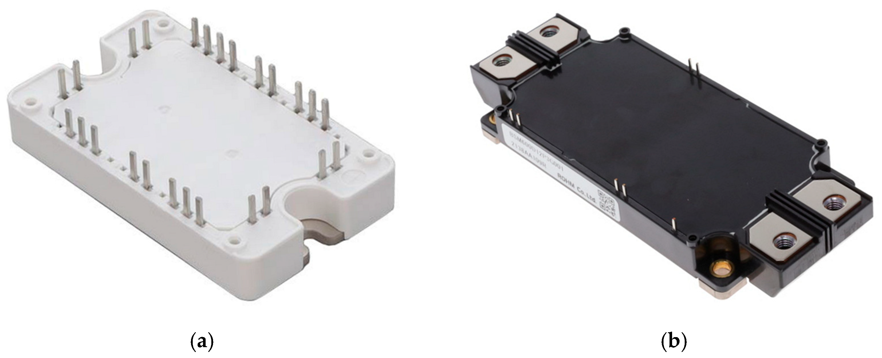
Figure 1 shows representative commercial SiC chopper modules with a 1200 V rating.
In the context of air mobility, hybrid power systems that combine fuel cells and batteries have gained attention for their potential to improve energy efficiency, extend flight range, and reduce emissions [
6,
7]. A well-designed power conversion system is essential for managing the energy flow between fuel cells, batteries, and propulsion systems, ensuring optimal performance and reliability [
8]. SiC chopper modules play a pivotal role in these hybrid systems by efficiently enabling seamless power conversion, reducing losses, and improving overall system stability. Therefore, the blocking diode that protects the fuel cell from reverse current can be eliminated by using SiC chopper modules, as shown in
Figure 2.
An essential element in ensuring system reliability is the implementation of a redundant power system. A redundant design incorporating both a main battery and an auxiliary battery enhances fault tolerance and operational safety. The main battery serves as the primary power source, supplying consistent energy for propulsion and onboard systems under normal conditions. The auxiliary battery acts as a backup, automatically engaging in the event of a main battery failure or sudden load spike, thereby ensuring uninterrupted operation [
9]. This dual-battery configuration reinforces operational stability and minimizes the risk of power loss during flight, contributing to the overall reliability of the UAM system.
This paper explores the design and implementation of a highly reliable power circuit configuration using SiC chopper modules for hybrid fuel cell and battery power systems in air mobility applications. It emphasizes reliability-enhancing techniques, including optimized circuit topologies, fault-tolerant designs, and thermal management strategies. Additionally, key factors such as bidirectional energy flow, electromagnetic interference (EMI) mitigation, and system redundancy are analyzed to ensure fail-safe operation. By adopting SiC-based power solutions, the UAM industry can achieve higher efficiency, improved reliability, and long-term sustainability, paving the way for the next generation of urban air transportation systems [
1,
3,
5].
2. Hybrid Fuel Cell and Battery Power System of UAM
2.1. Structure of Hybrid Fuel Cell and Battery Power System
In order to support the operations of UAM, including takeoff, cruising, and landing, high power is required. However, using batteries alone increases weight, so hydrogen fuel cells are employed as the primary power source. To address the slow response characteristics of the fuel cells, a hybrid power system is implemented, which includes batteries to provide power during rapid acceleration and energy recovery during deceleration. Additionally, to ensure the reliability of the UAM system, an auxiliary battery is incorporated, which can serve as an emergency power source during emergency landings, in addition to the main battery. This configuration, as shown in
Figure 3, ensures optimal performance, fault tolerance, and operational safety for UAM, enhancing overall reliability while reducing weight and energy consumption.
2.2. Design Parameters of Hybrid Fuel Cell and Battery Power System
The design parameters for the hybrid power system used in Urban Air Mobility (UAM) applications are shown in
Table 1. The fuel cell is the primary power source, with a maximum power output of 210 kW, and it operates within a voltage range of 320–520 V, with a maximum current of 600 A. The main battery provides supplementary power, with a maximum power output of 20 kW, and its voltage range spans from 740 V to 840 V. Additionally, the system includes an auxiliary battery, which can supply a maximum power of 50 kW and operates within a voltage range of 400 V to 750 V. These parameters ensure that the hybrid power system can meet the operational demands of UAM, providing both efficiency and reliability for takeoff, cruising, landing, and emergency scenarios.
3. Review of the Previous Works
High-efficiency power conversion converters for hybrid electric mobility systems based on multiple power sources have been actively studied and proposed in various configurations. An isolated converter for hydrogen fuel cell and battery power sources was proposed in [
10], but it includes too many power semiconductor devices in the current conduction path for power processing, which increases circuit complexity and is expected to reduce overall efficiency. In particular, the use of a large transformer makes the power system heavier, rendering it unsuitable for airborne mobility applications.
A non-isolated dual-input boost converter has been proposed for hybrid electric vehicles [
11]. This topology allows both the hydrogen fuel cell and the battery to operate either independently or simultaneously as power sources. Furthermore, an additional operating mode can be implemented in which the hydrogen fuel cell charges the battery. However, to prevent reverse current from the hydrogen fuel cell, a blocking diode is necessary, and a dedicated FET is used to manage the charging and discharging of the battery. As a result, two power semiconductor devices are involved in the current conduction path for each power processing mode, and up to three devices are conducted simultaneously during the battery charging mode. This reduces overall efficiency and may increase system weight due to the additional thermal management requirements.
An integrated boost converter is proposed for fuel cell hybrid vehicles with dual power sources [
12]. This topology includes a unidirectional port for the hydrogen fuel cell and bidirectional ports for the battery and load, enabling flexible and efficient power flow control. Both the fuel cell and the battery can operate independently or simultaneously to supply power, and the converter also supports a mode in which the fuel cell charges the battery to optimize overall energy management and system performance. To achieve the required high voltage gain without relying on bulky transformers, a switched-capacitor structure is incorporated. This approach enhances voltage boosting capability while maintaining a compact and lightweight design suitable for vehicular applications. However, the use of multiple power semiconductor devices in each power processing mode increases the conduction paths: typically, two devices are conducted during normal operation, with up to three devices being conducted simultaneously during battery charging. This leads to increased conduction losses and consequently reduces the overall efficiency of the system. Furthermore, the additional heat generated by these losses demands enhanced thermal management, which can add weight and complexity to the system—factors that are critical in hybrid electric vehicle design where both efficiency and weight savings are paramount.
4. Proposed Converter for Reliable UAM
4.1. Power Circuit Configuration
For the successful operation of Urban Air Mobility (UAM) during critical flight phases such as takeoff, cruising, and landing, a well-designed and highly reliable power circuit configuration is essential. This paper proposes a hybrid power circuit configuration that integrates a fuel cell, main battery, and auxiliary battery to ensure stable and efficient power management under varying load conditions, as shown in
Figure 4. As discussed in the Introduction, a SiC chopper module-based boost converter is employed to supply power to the traction inverter while simultaneously charging the main battery. The use of SiC chopper modules enables high efficiency and fast response times, which are critical for maintaining stable flight dynamics during rapid load changes. The boost converter configuration eliminates the need for a blocking diode to prevent reverse current from flowing into the fuel cell, thereby simplifying the circuit design and improving overall reliability. The high thermal conductivity and low switching losses of SiC technology enhance the thermal management of the system, ensuring stable operation even under high power demands. To charge the auxiliary battery, a buck converter is implemented, which also utilizes the same SiC chopper module. This approach simplifies the gate drive design by using a common source configuration, reducing complexity and enhancing overall system reliability.
The auxiliary battery serves as a backup power source, providing additional power during sudden load increases or in the event of a failure in the main power system. The SiC-based buck converter allows for efficient bidirectional power flow, enabling quick charging and discharging of the auxiliary battery. Furthermore, to prevent the fuel cell from directly charging the auxiliary battery and to enable natural power supply from the auxiliary battery in case of a main battery failure or disconnection, an auxiliary diode is incorporated into the circuit. This design ensures smooth power transition between the main and auxiliary batteries, maintaining uninterrupted power delivery to the traction inverter and other critical subsystems. The auxiliary diode also prevents unwanted current flow, further enhancing system stability and reliability.
This proposed hybrid power circuit configuration optimizes power management by balancing the energy supply from the fuel cell and batteries according to the real-time power demand. The combination of a boost converter for main battery charging and a buck converter for auxiliary battery charging enables high-efficiency energy utilization while minimizing losses. The use of SiC chopper modules enhances the overall durability of the system, reduces thermal stress, and extends the operational lifespan of the power components. By integrating these advanced design features, the proposed power circuit configuration significantly enhances the operational reliability, fault tolerance, and energy efficiency of UAM systems. The combination of fuel cells and batteries, managed through SiC-based power converters, provides a robust and adaptable solution for the next generation of Urban Air Mobility platforms. The distinctive features of the proposed converter compared to conventional converters in [
10,
11,
12] are summarized in
Table 2.
4.2. Circuit Parameter Design of Proposed Converter
To smooth the output current of the fuel cell, a boost converter comprising four parallel-connected boost cells is implemented, as illustrated in
Figure 4. This configuration requires four SiC chopper modules and four boost inductors. This configuration is designed to handle the high current demand of the system and requires a total of four SiC chopper modules to ensure efficient and reliable operation. In parallel, a buck converter is utilized to charge the auxiliary battery, which demands only one SiC chopper module due to its relatively lower power requirement.
Based on the comparative analysis of power losses in SiC chopper modules, as shown in
Figure 5, MSCSM120DAM11CT3AG demonstrates higher conduction losses than BSM300C12P3E201. However, its significantly lower switching losses compensate for this difference, resulting in a comparable total power loss across the operating voltage range. Additionally, MSCSM120DAM11CT3AG is packaged in a more compact form factor, which is highly advantageous for systems where space and layout flexibility are critical design constraints.
Given these considerations, all SiC chopper modules employed in the hybrid power system have been selected as MSCSM120DAM11CT3AG from Microchip. This choice is driven by the module’s high efficiency, excellent thermal performance, and compact design, all of which contribute to improved system integration and long-term reliability. The main characteristics of the selected SiC modules are summarized in
Table 3. For the auxiliary diode (D
Aux), MSCDC200KK120D1PAG of Microchip is adopted to ensure consistent performance and compatibility across the system.
The switching frequency of both boost and buck converters are chosen as 50 kHz to balance the conduction and switching losses of the SiC chopper module. The boost inductor L
BOOST and the buck inductor L
BUCK were designed to be the same, as shown in
Figure 6. Its core material is 40μ of high-flux Changsung (Incheon, Republic of Korea), the cross-sectional area A
e is 1000 mm
2, the magnetic path length L
e is 207 mm, and the core volume V
e is 212,000 mm
3. The number of turns is 12, and the nominal inductance is 55 μH.
5. The Operation Modes of the Proposed Converter
The normal operating sequence of UAM can be divided into five stages: preparation for departure, takeoff, acceleration, cruising, and landing. In the event of an emergency, the system should be designed to enable safe landing at any stage of the operating sequence. The detailed operation of the proposed circuit during each stage will be analyzed in the following sections.
5.1. Preparation for Departure
During the preparation for departure in UAM, operations such as airframe inspection and refueling of the primary power source, similar to conventional air mobility, are required. In particular, hydrogen fuel cell-based UAMs require hydrogen refueling into the hydrogen tank, along with additional operations to charge both the main battery and the auxiliary battery. Since the main battery directly contributes to the takeoff of the UAM together with the fuel cell, it is charged to its maximum voltage by operating the hydrogen fuel cell. After the normal operation of the UAM, the auxiliary battery can be assessed for emergency readiness by checking its voltage without the need for separate charging. If the voltage is low, it can be recharged using either a high-capacity external fast charger or the current output from the hydrogen fuel cell. The operations of the boost converter and buck converter in this stage are presented in
Figure 7.
5.2. Takeoff
Takeoff is the stage in UAM operation that consumes the highest power as the aircraft must overcome gravity and downdrafts. Increasing the power capacity of the fuel cell and the main battery to meet these high power demands would increase the overall weight of the aircraft, thereby reducing the operational efficiency of the UAM. Therefore, the power capacity of the fuel cell is selected based on the power consumption during cruising, while the main battery is sized to provide the required power during takeoff, considering gravitational acceleration without the effect of downdrafts. In the presence of strong downdrafts, the auxiliary battery can provide additional support, enabling the UAM to take off with maximum power.
Figure 8 shows the operations of the proposed converter in takeoff.
5.3. Acceleration
While maintaining altitude, the power consumption in UAM is relatively low. Even during acceleration, the power capacity of the fuel cell alone is generally sufficient. However, the main battery can temporarily provide support to compensate for the slow response of the fuel cell. The auxiliary battery maintains its state of charge without charging or discharging. The operations of the proposed converter during the acceleration of UAM are presented in
Figure 9.
5.4. Cruising
During cruising operations, the power required for UAM is very low. The main battery alternates between supplying and recovering energy in response to temporary acceleration, deceleration, or altitude changes caused by airflow. Since the electrical energy generated by the hydrogen fuel cell exceeds the power consumption of the traction inverter, the auxiliary battery can be gradually charged.
Figure 10 shows the operations of the proposed converter in cruising mode.
5.5. Landing
Most aviation accidents occur during landing, so special attention must be paid to safety. Since vertical takeoff and landing (VTOL)-based UAMs must involve landing precisely within designated areas, accurate landing control is essential. As the altitude decreases with the aid of gravity, power consumption is minimal, making the operation of the hydrogen fuel cell unnecessary during landing. The traction inverter can be controlled solely using the energy stored in the main battery. However, to reduce the charging time of the main battery for the next takeoff, the hydrogen fuel cell can operate at a reduced output power. The operations of the proposed converter during landing in UAM are presented in
Figure 11.
5.6. Emergency Landing
The hydrogen fuel cell, battery, and power converter are not perfect and must be designed to account for single-point failures. In the event of main battery failure, the auxiliary battery can take over and contribute to achieving safe landing. If the hydrogen fuel cell or power converter fails, the main and auxiliary batteries can work together to ensure safe landing. Even in the worst-case scenario, where both the hydrogen fuel cell and the main battery fail, the auxiliary battery must be capable of supporting an emergency landing. Therefore, its capacity should be selected accordingly. An advantage of the proposed converter is that it enables the seamless operation of the auxiliary battery in the event of a hydrogen fuel cell or main battery failure.
Figure 12 presents the operations of the proposed converter in emergency landing.
6. Operation Verification of Proposed Converter by Simulation
To verify the operation of the proposed converter throughout the entire UAM operation, simulations were conducted using PowerSIM under the boundary conditions shown in
Table 1 and the following assumptions:
The MOSFETs and SiC diodes within the SiC chopper modules, as well as the auxiliary SiC diode, were modeled as ideal switches without switching loss or parasitics.
The boost and buck inductors were assumed to be ideal, with no series resistance and no DC bias characteristics.
The main and auxiliary batteries were modeled using the built-in lithium-ion battery models provided by PowerSIM.
The traction load was modeled as an ideal current source using a piecewise linear current profile to simulate variable load conditions.
The components used in the simulation include the SiC module MSCSM120DAM11CT3AG, the auxiliary SiC diode MSCDC200KK120D1PAG, and the inductor shown in
Figure 6. After confirming the basic operation of the boost and buck converters that constitute the proposed system, the effectiveness of the converter for UAM operation will be validated.
6.1. Simulation of Four-Phase Interleaved Boost Converter
The boost converter not only drives the traction inverter using the high output power from the hydrogen fuel cell but also charges both the main battery and the auxiliary battery. To handle a rated power of 210 kW and an input current of 600 A, it operates in a four-phase interleaved configuration. Given that the voltage of the hydrogen fuel cell at maximum current output is 350 V and the nominal voltage of the main battery is 820 V, the schematic was implemented using PowerSIM, as shown in
Figure 13a. Here, n denotes the phase number, ranging from 1 to 4. The key simulation waveforms are presented in
Figure 13b, demonstrating that the four boost converters operate with a 90-degree phase shift and that the inductor currents are evenly distributed. The ripple of the current output from the hydrogen fuel cell is very small at only 1 Ap-p, and the average output current of the boost converter is measured to be 256 A considering the maximum output current of the hydrogen fuel cell.
6.2. Simulation of Buck Converter
The buck converter is dedicated to charging the auxiliary battery and operates independently from both the traction inverter and the main battery charging system. The auxiliary battery has a capacity of 80 kWh, and the maximum charging current is set to 150 A. The high-voltage bus formed by the main battery and the auxiliary battery have nominal voltages of 820 V, and the PowerSIM schematic is shown in
Figure 14a. The current waveforms of the buck inductor and the buck switch are illustrated in
Figure 14b. The ripple in the charging current of the auxiliary battery is measured to be 1.75 Ap-p.
6.3. Simulation of Proposed Converter with UAM Operation
To validate the operation of the proposed converter for the overall UAM mission profile, simulations were carried out using PowerSIM with the schematic presented in
Figure 15a. The parameters of the main and auxiliary batteries are adopted according to the Li-ion battery of PowerSIM in
Figure 15b,c, respectively. As shown in
Figure 16a, the system was simulated for 20,000 s following a standard operation sequence comprising the pre-departure, takeoff, acceleration, cruising, and landing phases. Initially, the auxiliary battery was assumed to have 80% SoC due to non-use in previous operations, while the main battery was assumed to have 40% SoC. During pre-departure, the hydrogen fuel cell charges the main battery up to 95% SoC at 820 V. To improve the battery lifespan, the auxiliary battery is charged only up to 85% SoC. Once charging is complete, takeoff begins with the hydrogen fuel cell and main battery supplying power to the traction inverter. During acceleration, the inverter’s power demand decreases, allowing the fuel cell to recharge the main battery. In cruising mode, depending on airflow, the main battery alternates between power supply and regenerative charging. During landing, inverter power demand drops, and the altitude is gradually reduced for passenger comfort. The hydrogen fuel cell slowly decreases the output while the main battery supports a safe descent.
Figure 16b shows the simulation of an emergency landing scenario caused by the simultaneous failure of the hydrogen fuel cell and the main battery during cruising, with a total simulation runtime of 20,000 s. In this case, the auxiliary battery starts at 45% SoC, assuming prior emergency use, and the main battery starts at 20% SoC. The system operates normally up to cruising, but upon failure, the auxiliary battery takes over, initiating an emergency descent within three minutes. Due to its limited capacity, the descent rate is faster than in normal landings to ensure safe touchdown.
6.4. Impact of Main and Auxiliary Battery Capacities
An increase in the main battery capacity enables faster compensation for the slow dynamic response of the hydrogen fuel cell, thereby contributing to stable UAM operation under sudden airflow disturbances. Additionally, the required power output from the hydrogen fuel cell during takeoff is reduced, which allows for downsizing of the boost converter. However, the increased battery capacity leads to greater system weight and longer charging times, resulting in delays during pre-takeoff preparation. The capacity of the auxiliary battery is determined primarily with emergency landing scenarios in mind. While a larger auxiliary battery can support a more stable descent during such situations, it also increases the charging time via the buck converter. Furthermore, since the auxiliary battery is not used during normal UAM operation, its weight contributes to reduced operational efficiency. In summary, increasing the capacities of the main and auxiliary batteries to ensure stable UAM operation results in both weight gain and an extended charging time. Maintaining the same charging duration would require higher power ratings for the boost and buck converters, which in turn may lead to decreased overall power conversion efficiency.
7. Limitations of Proposed Power Converter
The proposed power converter relies on the use of a SiC chopper module. In this context, the overall reliability of the converter is inherently dependent on the adoption of the SiC chopper module, and its performance is directly influenced by the power loss and thermal characteristics of the module. However, most commercially available SiC power modules on the market are designed in phase-leg or six-pack configurations, and dedicated SiC chopper modules are relatively limited. As a result, there are constraints in terms of available current ratings and blocking voltage options. Although a broader range of SiC chopper modules is expected to become available in the future, the selection will likely remain more limited compared to general SiC power modules. Furthermore, the commercial dependency on specific SiC chopper modules may lead to limited availability and potential cost increases. Since fewer manufacturers offer such specialized modules, supply chain disruptions or increased demand could drive up prices and reduce procurement flexibility. This could pose challenges in terms of cost optimization and the long-term scalability of the proposed converter system.
8. Conclusions
This paper proposes a reliable power circuit configuration using SiC chopper modules for hybrid fuel cell and battery systems in Urban Air Mobility (UAM) applications. The system integrates a fuel cell, main battery, and auxiliary battery, managed through high-efficiency boost and buck converters. This design addresses UAM’s demands—high power density, rapid load response, and improved reliability—by eliminating blocking diodes and enabling efficient bidirectional power flow. Key design aspects like thermal management, fault tolerance, and redundant energy storage were validated through simulation. The system performs effectively across all flight phases, including takeoff, cruising, landing, and emergency descent. SiC technology enhances power conversion efficiency and thermal stability, ensuring safety and sustainability. The study indicates that SiC-based power systems are a promising solution for next-generation UAM, offering a lightweight design, robustness, and long-term reliability. Future work will focus on hardware implementation and real-world validation.
The redundant power system implemented by the proposed converter can enhance robustness not only against environmental factors encountered in UAM but also against electrical disturbances originating from both internal and external sources. This aspect calls for deeper explorations in future research.
Author Contributions
Conceptualization, C.-E.K.; methodology, C.-E.K.; validation, M.-S.C.; formal analysis, M.-S.C. and C.-E.K.; investigation, M.-S.C.; resources, C.-E.K.; data curation, M.-S.C.; writing—original draft preparation, M.-S.C.; writing—review and editing, C.-E.K.; visualization, M.-S.C.; supervision, C.-E.K.; project administration, C.-E.K.; funding acquisition, C.-E.K. All authors have read and agreed to the published version of the manuscript.
Funding
This work was supported by the Korea National University of Transportation Industry-Academy Cooperation Foundation in 2025.
Data Availability Statement
The original contributions presented in this study are included in the article. Further inquiries can be directed to the corresponding author.
Conflicts of Interest
The authors declare no conflicts of interest.
References
- Kim, S.; Choi, Y.; Chang, D. Techno-economic analysis of fuel cell powered urban air mobility system. Int. J. Hydrogen Energy 2024, 50, 988–1004. [Google Scholar] [CrossRef]
- Yun, S.; Im, S.Y.; Han, J. Development of a hydrogen fuel-cell hybrid urban air mobility system model using a hydrogen metal hydride tank. Energies 2024, 18, 39. [Google Scholar] [CrossRef]
- Çınar, H.; Donateo, T. Conceptual design and sizing optimization based on minimum energy consumption of lift-cruise type eVTOL aircraft powered by battery and fuel-cell for urban air mobility. Aerospace 2022, 9, 123. [Google Scholar]
- Marzougui, T.; Neuhaus, K.; Labracherie, L.; Scalabrin, G. Optimal sizing of hybrid electric propulsion system for eVTOL. Aerospace 2022, 9, 112. [Google Scholar] [CrossRef]
- An, J.-H.; Kwon, D.-Y.; Jeon, K.-S.; Lee, J.-W. Advanced sizing methodology for a multi-mode eVTOL UAV powered by a hydrogen fuel-cell and battery. Aerospace 2022, 9, 71. [Google Scholar] [CrossRef]
- Guinea, D.M.; Roura, M.; García-Alegre, M.C.; Guinea, D. Specific weight: A challenge for a fuel-cell-powered electric helicopter. Aerospace 2007, 4, 12. [Google Scholar] [CrossRef]
- Nishizawa, A.; Kallo, J.; Garrot, O.; Weiss-Ungethüm, J. Fuel-cell and Li-ion battery direct hybridization system for aircraft applications. J. Power Sources 2013, 241, 294–300. [Google Scholar] [CrossRef]
- Liu, H.; Yao, Y.; Wang, J.; Yang, T.; Li, T. Energy Management and System Design for Fuel Cell Hybrid Unmanned Aerial Vehicles. Energy Sci. Eng. 2022, 10, 3987–4006. [Google Scholar] [CrossRef]
- Mazzeo, F.; Di Ilio, G. Fuel cell hybrid electric propulsion system for a lightweight helicopter: Design and performance analysis in urban air mobility scenario. Int. J. Hydrogen Energy 2024, 50, 891–907. [Google Scholar] [CrossRef]
- Bhattacharya, S.; Anagnostou, D.; Schwane, P.; Bauer, C.; Kallo, J.; Willich, C. A flexible DC–DC converter with multi-directional power flow capabilities for power management and delivery module in a hybrid electric aircraft. Energies 2022, 15, 5495. [Google Scholar] [CrossRef]
- Daya John Lionel, F.; Dias, J.; Krishna Srinivasan, M.; Parandhaman, B.; Prabhakaran, P. A novel non-isolated dual-input DC-DC boost converter for hybrid electric vehicle application. Int. J. Emerg. Electr. Power Syst. 2021, 22, 191–200. [Google Scholar] [CrossRef]
- Xie, W.; Luo, W.; Qin, Y. Integrated DC/DC Converter Topology Study for Fuel-cell Hybrid Vehicles with Two Energy Sources. World Electr. Veh. J. 2023, 14, 9. [Google Scholar] [CrossRef]
Figure 1.
Commercial SiC chopper modules: (a) MSCSM120DAM11CT3AG of Microchip (Chandler, AZ, USA), (b) BSM300C12P3E201 of Rohm (Kyoto, Japan).
Figure 1.
Commercial SiC chopper modules: (a) MSCSM120DAM11CT3AG of Microchip (Chandler, AZ, USA), (b) BSM300C12P3E201 of Rohm (Kyoto, Japan).
Figure 2.
Boost converter with fuel cell input adopting (a) SiC phase-leg module and (b) SiC chopper module.
Figure 2.
Boost converter with fuel cell input adopting (a) SiC phase-leg module and (b) SiC chopper module.
Figure 3.
Block diagram and power flows of hybrid fuel cell and battery power system.
Figure 3.
Block diagram and power flows of hybrid fuel cell and battery power system.
Figure 4.
Power circuit configuration of proposed converter.
Figure 4.
Power circuit configuration of proposed converter.
Figure 5.
Power loss comparison of two SiC chopper modules at 50 kHz switching frequency.
Figure 5.
Power loss comparison of two SiC chopper modules at 50 kHz switching frequency.
Figure 6.
Inductor design for both boost and buck converters with the unit of mm.
Figure 6.
Inductor design for both boost and buck converters with the unit of mm.
Figure 7.
Current path of proposed converter in preparation for departure stage.
Figure 7.
Current path of proposed converter in preparation for departure stage.
Figure 8.
The current path of the proposed converter in the takeoff stage.
Figure 8.
The current path of the proposed converter in the takeoff stage.
Figure 9.
Current path of proposed converter in acceleration stage.
Figure 9.
Current path of proposed converter in acceleration stage.
Figure 10.
Current path of proposed converter in cruising stage.
Figure 10.
Current path of proposed converter in cruising stage.
Figure 11.
Current path of proposed converter in landing stage.
Figure 11.
Current path of proposed converter in landing stage.
Figure 12.
Current path of proposed converter in emergency landing stage.
Figure 12.
Current path of proposed converter in emergency landing stage.
Figure 13.
Simulation of boost converter; (a) PowerSim schematic; (b) key waveforms.
Figure 13.
Simulation of boost converter; (a) PowerSim schematic; (b) key waveforms.
Figure 14.
Simulation of buck converter; (a) PowerSim schematic; (b) key waveforms.
Figure 14.
Simulation of buck converter; (a) PowerSim schematic; (b) key waveforms.
Figure 15.
Simulation of proposed converter with UAM operation: (a) PowerSim schematic; (b) main battery parameters; (c) auxiliary battery parameters.
Figure 15.
Simulation of proposed converter with UAM operation: (a) PowerSim schematic; (b) main battery parameters; (c) auxiliary battery parameters.
Figure 16.
Simulation of proposed converter: (a) normal operation; (b) emergency landing with failure of both fuel cell and main battery. A dash line represents the temporal boundary at which each mode changes.
Figure 16.
Simulation of proposed converter: (a) normal operation; (b) emergency landing with failure of both fuel cell and main battery. A dash line represents the temporal boundary at which each mode changes.
Table 1.
Design parameters of hybrid fuel cell and battery power system.
Table 1.
Design parameters of hybrid fuel cell and battery power system.
| Design Parameter | Value |
|---|
| Max. Power of Fuel Cell | 210 kW |
| Voltage Range of Fuel Cell | 330–520 V (Nominal 350 V) |
| Max. Current of Fuel Cell | 600 A |
| Max. Power of Main Battery | 20 kW |
| Voltage Range of Main Battery | 740–840 V (Nominal 820 V) |
| Max. Power of Aux. Battery | 80 kW |
| Voltage Range of Aux. Battery | 680–740 V (Nominal 720 V) |
Table 2.
Comparison of power converter topologies based on key performance criteria.
Table 2.
Comparison of power converter topologies based on key performance criteria.
| Comparison Item | Converter [10] | Converter [11] | Converter [12] | Proposed Converter |
|---|
| Circuit Complexity | Very high | Moderate | High | Simple |
| Conduction Losses | High
(multiple devices) | Medium to high
(2–3 devices) | Medium to high
(2–3 devices) | Low
(1–2 SiC devices) |
| Transformer Requirement | Yes (bulky) | No | No | No |
| Weight and Size | Heavy | Moderate | Compact | Compact |
| Power Source Flexibility | Dual
(but limited) | Dual with
charge mode | Dual (uni/bidirectional) | Triple (fuel cell + 2 batteries) |
| Reverse Current Prevention | Achieved
via isolation | Blocking diode | Blocking diode | Intrinsically handled by topology |
| Thermal Management | Demanding | Moderate to high | Moderate to high | Simplified
(SiC advantages) |
| UAM Applicability | Poor | Moderate | Good | Excellent |
Table 3.
Key characteristics of SiC module, MSCSM120DAM11CT3AG.
Table 3.
Key characteristics of SiC module, MSCSM120DAM11CT3AG.
| Component | Parameter | Typical Value |
|---|
SiC
MOSFET | Drain–source voltage (VDSS) | 1200 V |
| Continuous drain current (ID) | 254 A (Tc = 25 °C) |
| Drain–source ON resistance (RDSon) | 10.4 mΩ (Tj = 25 °C) |
| Power dissipation (PD) | 1067 W (Tc = 25 °C) |
| Input capacitance (Ciss) | 9060 pF |
| Output capacitance (Coss) | 810 pF (VDS = 1000 V) |
| Reverse transfer capacitance (Crss) | 750 pF (VDS = 1000 V) |
| Internal gate resistance (RG,int) | 2.0 Ω |
| Thermal resistance (RthJC) | 0.141 °C/W |
SiC
Diode | Peak reverse voltage (VRRM) | 1200 V |
| DC forward current (IF) | 180 A (Tc = 25 °C) |
| Total junction capacitance (Cj) | 630 pF (VR = 800 V) |
| Thermal resistance (RthJC) | 0.175 °C/W |
| Total | Max. junction temperature (TJ,max) | 175 °C |
| Disclaimer/Publisher’s Note: The statements, opinions and data contained in all publications are solely those of the individual author(s) and contributor(s) and not of MDPI and/or the editor(s). MDPI and/or the editor(s) disclaim responsibility for any injury to people or property resulting from any ideas, methods, instructions or products referred to in the content. |
© 2025 by the authors. Licensee MDPI, Basel, Switzerland. This article is an open access article distributed under the terms and conditions of the Creative Commons Attribution (CC BY) license (https://creativecommons.org/licenses/by/4.0/).


