Abstract
In support of global efforts to strengthen the nuclear non-proliferation regime, the IVG.1M research water-cooled thermal reactor at the National Nuclear Center of the Republic of Kazakhstan was successfully converted to low-enriched uranium (LEU, 19.75% 235U) fuel in 2023. The reactor’s operability with innovative bimetallic, fiber-type, dual-blade LEU fuel rods was experimentally verified during power start-up experiments. The test program included investigations of power distribution in the core, evaluation of temperature, power, and hydrodynamic reactivity effects, and the measurement of fission product release to the coolant. The results were in good agreement with safety calculations, confirming that the enrichment reduction did not degrade reactor performance characteristics. It was shown that the power reactivity effect increased by more than 1.5 times at a power level of 9 MW. The measured temperature reactivity coefficient (≈0.021 βeff/°C) and the level of fission product release remained within acceptable and expected limits.
1. Introduction
In 1978, the United States initiated a program to reduce the enrichment of research reactors, the main goal of which was to prevent the proliferation of nuclear weapons. With regard to the concerns about safety issues in the use of highly enriched uranium (HEU) fuel in the international community, an International Nuclear Fuel Cycle Assessment was conducted in 1980 with the financial support of the United Nations, which concluded that it was necessary to reduce fuel enrichment for research reactors to less than 20% of 235U [1].
Unlike the fuel used in power nuclear reactors (235U enrichment was 3–5%), many research reactors historically operated on the fuel with HEU, that is, more than 20% of 235U. Higher enrichment makes it possible to use compact cores with a higher neutron flux, longer intervals between the fuel overloads and wider operational possibilities. However, most research reactors currently operate using low-enrichment (LEU) fuel or can be converted to use it without loss of their operational characteristics.
To date, according to the International Atomic Energy Agency (IAEA), 109 research reactors and large nuclear isotope installations have been converted from HEU to LEU or have been shut down, and the HEU fuel has been returned to the country of origin or otherwise removed from 48 countries [2].
The conversion from HEU to LEU has a significant impact on the reactor neutronic and thermophysical characteristics [3]. This includes the changes in power distribution, heat transfer parameters and reactivity control. For instance, to convert reactors such as the VVR-M2, VVR-K, and MARIA while maintaining the original thermal neutron flux density, the uranium loading in the fuel matrix was increased. As a result, fuel assemblies (FAs) with dispersion-type UO2-Al fuel containing 2.5–4 g U/cm3 were developed and implemented. For the IRT-3M reactor, LEU fuel rods based on high-density uranium–molybdenum (U-Mo) dispersion and uranium density up to 8 gU/cm3 were developed [4]. The operability of UO2-Al metal–ceramic fuel enriched to 19.7% 235U was experimentally confirmed during the final stages of LEU conversion of the VVR-K reactor. The developed fuel rods and assemblies demonstrated reliable thermal performance due to the increased heat transfer surface area [5,6,7].
The conversion to LEU may lead to a change in the axial and radial power distribution in the core, which requires a revision of the reactor control and protection system. Changes in fuel composition affect the thermophysical properties such as thermal conductivity and temperature coefficients of the reactivity, which should be taken into account during the safety analysis. For instance, during conversion of the Ghana Research Reactor-1 (GHARR-1), LEU fuel showed lower temperature rise in transients and more moderate power peaks [8]. In addition, the reactors with the LEU fuel usually have lower reactivity compared to HEU, which requires adaptation of the reactivity control system, including changing the layout of the control rods and adjusting the fuel loading strategy [9].
There are repercussions that were noted as general trends during the conversion of research reactors (challenges and limitations):
- It is necessary to increase the 235U fissile isotope mass to maintain the current parameters (power density and neutron flux) of the core.
- The core volume increases. To compensate for the lower 235U concentration, more fuel is required, which increases the core physical size and complicates the layout.
- LEU reactors, as a rule, require more frequent fuel replacement due to the fuel’s lower initial energy intensity.
- There is a need to redesign the fuel and/or core. Many reactors required the recycling of fuel assemblies and the design of fuel rods or cooling systems to adapt to the new fuel.
In 2018, Nigeria’s research reactor, the Nigeria Research Reactor-1 (NIRR-1), was converted from using HEU LEU with an enrichment level of approximately 13% in 235U. This conversion required several modifications to the reactor core configuration. The transition to LEU led to a slight “hardening” of the neutron spectrum due to the increased content of 238U. Additionally, the thermal power was increased from 31 kW to 34 kW to compensate for the reduction in neutron flux [10].
According to the international safety standards, after design modifications, an extensive experimental verification of reactor operability is performed during physical and power start-ups [11,12]. During the physical start-up, the main task is to achieve the reactor first critical state and conduct experiments to determine the neutronic characteristics, including the evaluation of the reactivity of the core to confirm the compliance with the design values [13]. The power start-up is usually associated with checking the reactor operating modes at transient and stationary power levels and clarifying the reactor neutronic and thermal engineering characteristics. The power start-up includes thermophysical tests at various power levels to evaluate the thermal characteristics and confirm the cooling system effectiveness, as well as monitoring fission product emissions to assess the fuel integrity and the treatment system efficiency [14].
The program of the power start-up and the research methodologies employed are largely determined by the reactor type and specific design and functional features. For example, the power start-up program of the IBR-2M pulsed fast reactor included studies of the operational reactivity margin, power reactivity coefficients (both fast and slow components), and measurements of the isothermal and sodium flow rate reactivity effects [15]. During the power start-up of the DALAT reactor, which uses VVR-M2 fuel assemblies enriched to 19.75%, measurements of thermal neutron flux at different power levels, the xenon poisoning effect, and other reactivity-related effects were carried out [16]. For the PARR-1 reactor, after conversion and changing the nominal power from 5 to 10 MW, the experimental results confirmed the expected neutronic parameters, with the exception of the calculated excess reactivity, which was found to be 9% higher than the measured value [17].
In 2023, the National Nuclear Center of the Republic of Kazakhstan finished a major project to convert the IVG.1M research reactor to HEU fuel. The main objective of the project was to reduce the fuel enrichment to below 20% in accordance with IAEA requirements [18]. A key requirement for the conversion was maintaining the reactor operational characteristics.
The project involved extensive research, including the selection of suitable LEU fuel and FAs, the development of technical requirements, reactor and post-reactor fuel testing, and safety analysis of reactor operation with LEU fuel. Based on computational justification, physical and mathematical reactor models were created, neutronic and thermal–hydraulic parameters of the LEU fueled reactor were calculated, and kinetic processes were simulated and analyzed [19,20]. The theoretical study results enabled the selection of an optimal core configuration without modifying its structural elements—only adjusting the material properties of the FAs and fuel rods.
As a result of the conversion, the LEU fuel rods acquired a heterogeneous core structure: the uranium–zirconium alloy was replaced with a zirconium matrix with filaments of metallic uranium enriched to 19.75% in 235U. This approach enabled us to preserve the geometry of the FAs and the thermal neutron flux density.
During the physical start-up in 2022, the main neutronic characteristics of the IVG.1M research reactor were assessed: the reactivity worth curves of the control and reactivity compensating elements were obtained, axial and radial power distributions in the FAs were measured, and a high reactivity margin was confirmed. The experimental results showed good agreement with preliminary neutronic calculations [21].
In 2022–2023, a power start-up of the reactor was conducted to refine the calculated operational and neutronic characteristics of the reactor with WCTC-LEU at nominal power levels. Since all neutronic and thermal calculations were based on the assumption of a homogeneous fuel distribution within the fuel rod matrix, particular attention was given to studying the effects of enrichment and the heterogeneous fuel composition on reactivity control under various temperature and hydraulic operating conditions.
The objective of this study was to review the main experimental results obtained during the power start-up: achievement of nominal power, comparison of reactivity effects during operation of LEU and HEU fuel, and examination of the fission product release into the coolant. The assessed reactivity effects were compared with safety analysis data. The consistency of these results confirms the reliability of the calculation methods used.
2. The IVG.1M Research Reactor
The IVG.1M research reactor is a modernized version of the IVG.1 reactor, originally designed for testing fuel assemblies and cores of high-temperature gas-cooled reactors, as well as the FAs of nuclear rocket engines. The modernization involved the reconstruction of the cooling system and replacing the gas-cooled technological channels with water-cooled technological channels (WCTCs). Based on the results of the physical and power start-ups in 1990, the IVG.1M was commissioned. A set of FAs with enrichment of 90% in 235U within the WCTCs was successfully operated until 2020.
The IVG.1M research reactor is a water-cooled heterogeneous thermal neutron reactor with a design power of 60 MW. However, due to cooling system limitations, its operational power is currently restricted to 10 MW. The reactor core is surrounded by a beryllium neutron reflector on the sides and top. In the core, 30 WCTCs are loaded in separate cells arranged in three concentric circles with a radius of 156 mm (first row), 163.5 mm (second row), and 239 mm (third row). The first and second rows each have six cells, while the third row contains 18. The height of the FAs in the rows is different: the height of the FAs for the first and second rows of WCTCs is 800 mm, and for the third row it is 600 mm. The diameter of the WCTC is 76 mm. The LEU core contains a total of 5.87 kg of 235U; for comparison, the reactor core with HEU fuel contained 4.9 kg of 235U. The interchannel space is filled with beryllium displacers, which house activation detectors and material samples for research.
The main reactivity control and emergency protection are managed by a system of 10 rotary control drums (CDs) arranged in a circular pattern within the side reflector. Each CD contains two zones: absorptive and reflective. Each CD is driven by an individual stepper motor, allowing rotation from 0° (absorptive layer facing the core) to 180° (reflective layer facing the core). One motor step rotates the drum by 0.3°. The steps are sequential. Each CD rotates one after the other until it reaches the same position.
The reactor reactivity compensation system consists of 12 beryllium rods arranged around the central experimental channel. Currently, these rods have been removed from the core due to a sufficient reactivity margin following fuel conversion. The vacant volume left by the rods is filled with water. Figure 1 shows the sectional view of the IVG.1M, indicating the WCTC positions.
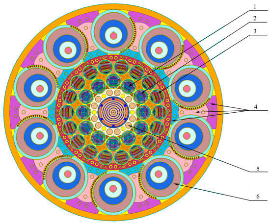
Figure 1.
Cross section of the IVG.1M research reactor (RR). 1: Water-cooled technological channel (WCTC) of the 1st row; 2: WCTC of the 2nd row; 3: WCTC of the 3rd row; 4: reflector; 5: reactivity compensation rods; 6: control drums (CD).
LEU fuel rods are drill-like rods with an external diameter of 2.8 mm. Their core consists of a zirconium alloy with metallic uranium filaments uniformly distributed in the cross section [22,23]. The fuel rods are clad in a zirconium alloy. The 235U enrichment is 19.75%. The FA of WCTC-LEU consists of 468 fuel rods. Detailed information about the fuel assembly is presented in [20].
As part of the conversion, the configuration of FAs of the first and second WCTC row was optimized. The end grid dividing the fuel assemblies into upper (200 mm) and lower (600 mm) parts was removed. Instead, the LEU FAs of the first and second rows are solid fuel rods. The configuration of the third-row FAs remains unchanged.
The reactor is forced-cooled using a single-circuit system. Distilled water is used as coolant and moderator. The water system includes the main and emergency reactor coolant systems. The operation of the emergency cooling system is based on a displacement method of supplying water to the reactor.
During nominal operation, water is supplied from the pressure manifold via four pathways to cool the central assembly, loop channel, reflector, and reactor cover. It then enters the collection chamber under the reactor cover, cools the fuel in the WCTCs and flows into the discharge manifold, which acts as a heat accumulator. To ensure the required water flow, three high-capacity pumps are used during reactor start-up, while two low-capacity pumps ensure safe reactor cooling during low-energy modes.
The water system lacks heat exchangers for cooling the coolant during reactor start-up. However, the reactor coolant system can be used to accelerate coolant cooling in the discharge tank between start-ups [24].
3. Objectives and Procedure for the Power Start-Up of the IVG.1M Research Reactor with Low-Enriched Uranium Fuel
As a general procedure, power start-up involves bringing the reactor from low, minimally controlled power levels to intermediate levels, stabilizing operation at these levels, conducting equipment and system tests, and refining operational parameters under power conditions.
The following questions were posed before the power start-up:
- Are the reactor thermal parameters maintained? This is important to consider when commissioning the reactor. While hydraulic characteristics were not expected to change during conversion, minor modifications to the first and second rows of LEU fuel assemblies could impact channel hydraulic resistance.
- Is it possible to reproduce the results of computer simulation of the reactor operating on new fuel [25]? The positive results of the tests confirm prior safety analysis conclusions, based on neutron and thermal modeling of various events in the reactor. Such tests include volumetric power distribution measurements and reactivity feedback evaluation.
- What is the impact of the coolant flow rate reactivity effect that is not taken into account in the safety analysis?
- Are the LEU fuel rods reliable to operate safely? Since the fuel rods act as a primary barrier to the release of fission products, the power start-up serves as the final test of the newly manufactured fuel rods.
The power start-up of the IVG.1M reactor was conducted in a series of nine separate reactor start-ups. At the time of the power start-up, the core configuration included 30 WCTCs and an empty experimental channel. Based on safety considerations, a sequential implementation of steady-state power levels from 0.1 to 10 MW was provided during power start-up. The thermal condition of the reactor was monitored based on coolant temperature, flow rate, and pressure in the cooling paths.
4. Study of the Reactor Thermal–Hydraulic Parameters
The thermal power of each WCTC-LEU was calculated from the recorded coolant temperature in the manifold and at the WCTC outlet, as well as the flow rate in the channels:
where
- Qi—water flow rate through the ith WCTC, kg/s;
- Cp—water specific heat capacity at an average temperature in the WCTC, J/(kg∙°C);
- Tin—water temperature at the reactor inlet, °C;
- Tout—water temperature at the WCTC outlet, °C.
The reactor thermal power is determined as the sum of the thermal power of six WCTCs in the 1st row, six in the 2nd row, and eighteen in the 3rd row.
The methodological error in determining the power for each WCTC is 3.4%.
Table 1 presents the values of the reactor thermal power and the average power of WCTC for each row, obtained from 18 steady-state modes of nine start-ups. The maximum nominal thermal power of the IVG.1M reactor was reached during start-up #05 and was 10.22 MW.

Table 1.
Thermal power of water-cooled technological channels with low-enriched uranium (WCTC-LEU) during the power start-up of the IVG.1M reactor.
Figure 2 shows the relative power distribution across the rows of WCTCs, obtained by normalizing the power value of each WCTC to the average power of the third-row WCTCs. For comparison, Figure 2 also presents a similar distribution for HEU fuel. The data for the HEU fuel were obtained from experiments conducted from 2017 to 2020, during which two experimental WCTCs-LEU were placed in core cells 14 and 24. The standard deviation of the relative power distribution for LEU WCTCs did not exceed 0.03. For HEU fuel, the standard deviation was ~0.045 for the first and second rows and 0.07 for the third row. It is noteworthy that for HEU fuel, the power in WCTCs #1 and #6 was systematically lower than the row average. It can be assumed that the 235U fissile isotope content in these two channels was most likely lower than in other channels of this row. Overall, the power distribution became more uniform after the fuel replacement.
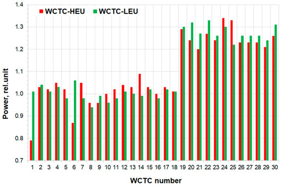
Figure 2.
Comparison of the relative power distribution for highly enriched uranium (HEU) and low-enriched uranium (LEU) cores.
The decisions on the WCTC modernization did not involve any changes to the hydraulic characteristics of the channels. This is because the WCTCs for HEU and LEU fuel are geometrically identical, with the exception of the intermediate end grid separating the upper and lower fuel rod bundles in the HEU FA. The values of the reactor cooling parameters recorded during the power start-up confirm that the thermohydraulic operation of the reactor has remained almost unchanged after the core conversion. All reactor thermal parameters were in compliance with the required design values during power start-up.
5. Study of Power Distribution in the Reactor Core
Table 2 presents a comparison of the power distribution across the rows of the WCTCs based on the results obtained during power start-up (thermal method), the physical start-up (activation method) [26], and computer modeling results [19].
Table 2.
Power distribution across the WCTC rows.
According to the research results presented in this paper, the power distribution across the core after fuel conversion is almost the same as before. The computer modeling results for both core configurations are consistent with the experimental data. This confirms the reliability of the reactor computational model and the accuracy of the results obtained using this model for analyzing the characteristics of the IVG.1M reactor after conversion.
6. Studying the Reactivity Effects
During reactor operation, any change in technological parameters (fuel and coolant temperatures, material density, coolant flow rate, etc.) can affect reactivity. The resulting reactivity effect is characterized by the corresponding reactivity coefficient [27]:
where
- ∆R—reactivity increment, βeff;
- ∆x—parameter increment.
To prevent heating of the reactor core components, reactivity experiments were conducted with the reactor operating at a minimally controlled power level (MCL, W = 1 kW). During these experiments, the CD position, reactor power, coolant temperature, and flow rate were recorded. The change in reactivity (or reactivity margin, RM) was determined using the CD reactivity worth curve by analyzing differences in CD positions at various states of the reactor core. The CD reactivity worth curve was measured during the reactor physical start-up [21].
The calculated data were compared with the experimental results to validate the computational methods [19] used for safety analysis. The error in measuring the reactivity effects was estimated from 5% to 10% and was determined by the error of the reactivity curve (5%), the error in determining the critical positions of the CD (0.0017 βeff), as well as the incompleteness of the reactor behavior description due to the limited number of parameters used during the reactor long-term operation.
6.1. Determining the Temperature Coefficient of Reactivity
Two different reactor experiments were conducted for the temperature coefficient of reactivity (TCR) measurements. To change the reactor temperature, the coolant was circulated through the reactor from two external sources with different temperatures, T1 and T2. The circulation lasted long enough to equalize the temperature throughout the reactor volume.
Table 3 and Table 4 present the initial (state 1) and final (state 2) reactor parameter values from the experiments: the reactor average coolant temperature and reactivity margin (RM).
Table 3.
Temperature coefficient of reactivity (TCR) results during experiment #1.
Table 4.
Temperature coefficient of reactivity (TCR) results during experiment #2 [28].
For the HEU-fueled core, the TCR value was 0.021 βeff/°C. The calculated value of the TCR is 0.015 ± 0.003 βeff/°C. The difference between the calculated and experimental values is attributed to the temperature range used in the calculations (20 °C to 50 °C).
6.2. Determining the Power Reactivity Effect
The power reactivity effect (PRE) represents the change in reactor reactivity ΔR as the reactor power ΔN varies. PRE measurement involved comparing the position of the CD system at MCL and the steady-state (SS) reactor power levels. Since PRE measurements were conducted over a short period, long-term coolant temperature changes at the reactor inlet were negligible. During start-ups #05 and #07, coolant temperature effects were considered in reactivity margin calculations, with inlet water temperature increasing by 2 °C in start-up #07 and 1 °C in start-up #05.
Table 5 presents reactor start-up data used for PRE calculations, including reactor power N, reactivity margin at MCL and SS, and PRE results.
Table 5.
Results of determining the power effect of reactivity (PRE).
As shown in Table 5, the PRE is negative throughout the reactor power range. Figure 3 shows the experimental dependence of the reactivity effect on reactor power for LEU and HEU fuels. In comparison with the HEU fuel data, the power reactivity effect is more pronounced: at a power level of 9 MW, the effect increased by more than 1.5 times, which is attributed to the greater 238U content and the enhanced Doppler effect.
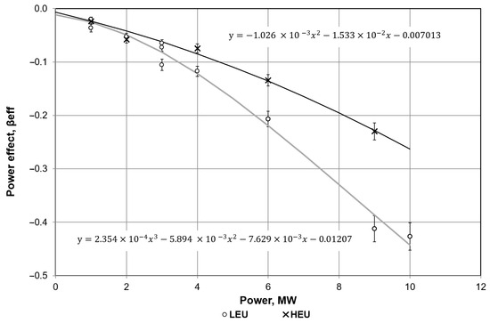
Figure 3.
Reactor power reactivity effect.
The discrepancies in the behavior of the reactivity curve with increasing reactor power level (the reactor power effect on reactivity) can be explained by the fact that the content of 238U in LEU fuel is approximately 40 times higher compared to HEU fuel. Accordingly, the effect of neutron capture in 238U with increasing fuel temperature should be more pronounced. At reactor power levels up to 1 MW, the temperature of the fuel element core (fuel) likely changes only slightly, and this effect is weakly manifested.
The calculated values of the PRE (Table 5) were obtained using the software, which was applied for analyzing Reactivity-Initiated Accident (RIA) scenarios as part of the Safety Analysis Report (SAR) [19]. The PRE was evaluated as the sum of the reactivity effects resulting from reactor transition between different power levels. Power variation affects the temperature distribution within the core, changes the coolant density, and slightly alters the geometry of core components, which in turn affects the volume of the cooling circuit in the core. The comparison between experimental and calculated values confirms the conservativeness of the reactivity assessment methods employed in the safety analysis of RIA scenarios.
6.3. Determination of the Hydrodynamic (Flow Rate) Reactivity Effect
The hydrodynamic reactivity effect (HRE) is the change in reactor reactivity caused by variations in the coolant flow rate through the reactor. In the IVG.1M research reactor, an increase in coolant flow rate also leads to a rise in pressure within the reactor vessel, resulting in an additional barometric effect. Since these effects are small, it is not practical to separate them.
The experiment with the flow rate increasing was carried out at the MCL of reactor power over a short period of time (approximately 15 min), which excluded coolant heating and the influence of temperature effects on the HRE. The HRE was determined by comparing the reactivity margin at coolant flow rates of 5 kg/s and 65 kg/s, accompanied by corresponding pressure changes. The experimental parameters and results are presented in Table 6. The error in determining the hydrodynamic (barometric) reactivity effect did not exceed 10%.
Table 6.
Results of the experiment to determine the hydrodynamic reactivity effect (HRE).
The increase in coolant flow rate and pressure resulted in a positive reactivity effect. The opposite reactivity effect should occur with a decrease in pressure and flow. Conversely, a decrease in pressure and flow rate is expected to produce a negative reactivity effect. Scenarios involving partial or complete loss of coolant, where a barometric reactivity effect may occur, must be considered in the SAR. The experimental results confirm that neglecting the barometric reactivity effect represents a conservative approach to the SAR.
7. Monitoring of Fuel Fission Product Activity in the Coolant
One of the key requirements of the conversion was to ensure the safe operation of the LEU fuel. To achieve reduced enrichment, it was necessary to increase the uranium content (both 235U and 238U) in the fuel by approximately 5.5 times and to change the homogeneous fuel rod core to a heterogeneous design.
During the power start-up, fission product (FP) release into the coolant was monitored to assess the integrity of the LEU fuel rods. Fuel rod leak tightness was evaluated based on the activity levels of FP in the coolant. The key parameter was the ratio of the FP release rate in the coolant to its birth rate (R/B ratio). The coolant activity was determined by the sampling gamma spectrometric method [28] during start-ups #01, #02, #08, and #09. Measurements were performed using an Inspector 2000 gamma spectrometer with a GC1518 coaxial semiconductor detector.
Table 7 presents the specific activities and the R/B ratio of the reference FP in the FAs of the second and third rows of the WCTCs for start-up #09. The uncertainty in determining the R/B ratio was less than 30%.
Table 7.
Radiation characteristics of the WCTC-HEU and WCTC-LEU coolant.
There are no data on the I-135 isotope for the WCTC-HEU configuration in Table 7 because no such studies have been conducted for WCTC-HEU. The FP activity in the coolant is attributed not only to the release from the fuel core, but also to the surface contamination of the fuel rod cladding during the manufacturing. In the complete absence of FP release from the core, it is the surface contamination that determines the background R/B level. The R/B values for WCTC-LEU are comparable to those for WCTC-HEU [29]. Thus, changes in fuel enrichment, increased uranium content, and modifications in fuel core manufacturing technology did not affect the level of FP activity in the coolant.
8. Summary and Future Work
The power start-up of the IVG.1M research reactor was carried out in a series of nine start-ups, each reaching operational power levels. Based on the results of the experiments, the following conclusions can be drawn:
- The power distribution within the reactor core is practically identical to that observed before the conversion, as confirmed by the preliminary computer modeling and the results of the physical start-up experiments.
- The temperature coefficient of reactivity for both LEU and HEU fuel in the IVG.1M reactor is positive within the operating range and is 0.02 βeff/°C. The agreement of the values is explained by similar thermohydraulic operating conditions.
- The power reactivity effect has a negative value throughout the reactor power range and becomes more pronounced with reduced fuel enrichment, contributing to enhanced inherent safety.
- The hydrodynamic (barometric) reactivity effect has been determined. It is positive and equal to +0.028 βeff.
- Changes in fuel content and enrichment in the fuel rods did not significantly affect the release of fission products into the coolant. The R/B levels for LEU and HEU fuel are comparable. The fuel rod cladding thickness (250 µm) is impervious to 235U fission fragments. The intermetallic composition itself is also a barrier: uranium filaments in a zirconium matrix.
The analysis shows that the LEU core of the IVG.1M exhibits thermal and neutronic characteristics similar to the HEU core, with the exception of a higher reactivity margin and reactivity power effect. The feasibility of the reactor’s conversion, the accuracy of performance predictions, and the justification of the reactor safety are confirmed by the experimental results.
The reactor has been operating normally since 2023. It is planned to continue research in the field of radiological materials science [30,31], fuel assembly testing, and the study to support the development and safe operation of a nuclear power plant in the Republic of Kazakhstan [32]. It is also worth mentioning the reactor studies on the interaction between hydrogen isotopes and structural materials of nuclear and fusion facilities [33] and the study of the processes involved in converting the energy of nuclear reactions into optical radiation energy [34].
Author Contributions
Project Administration, E.B., V.V. and V.B.; Conceptualization E.B. and V.V.; Supervision, V.B., V.G. and A.A.; Data Curation, V.G.; Resources, A.A.; Methodology, R.S. and Y.P.; Visualization, Y.M. and R.S.; Validation, I.P. and R.I.; Writing—Review and Editing, I.P., R.S. and R.I.; Investigation, Y.P.; Formal Analysis, R.I. and I.P.; Writing—Original Draft, Y.M. All authors have read and agreed to the published version of the manuscript.
Funding
The paper was financially supported by the Committee of Science of the Ministry of Science and Higher Education of the Republic of Kazakhstan (Target-Oriented Financing Project BR21882185 “Research in Support of Construction and Safe Operation of a Nuclear Power Plant in the Republic of Kazakhstan”).
Data Availability Statement
Data are available on request from the corresponding author. The data are not publicly available due to internal safety regime at a nuclear reactor.
Acknowledgments
The authors gratefully acknowledge the Argonne National Laboratory (ANL, USA) for the invaluable support, expertise, and collaboration in the IVG.1M reactor conversion project.
Conflicts of Interest
The authors declare no conflicts of interest.
Abbreviations and Symbol Index
The following abbreviations are used in this manuscript:
| LEU | Low-enriched uranium |
| HEU | Highly enriched uranium |
| IAEA | International Atomic Energy Agency |
| FA | Fuel assembly |
| WCTC | Water-cooled technological channel |
| CD | Control drum |
| MCL | Minimally controlled power level |
| RM | Reactivity margin |
| TCR | Temperature coefficient of reactivity |
| PRE | Power reactivity effect |
| SS | Steady state |
| RIA | Reactivity-Initiated Accident |
| SAR | Safety Analysis Report |
| HRE | Hydrodynamic (flow rate) reactivity effect |
| FP | Fission product |
| Ni | Thermal power of WCTC-LEU (MW) |
| Qi | Water flow rate through the ith WCTC (kg/s) |
| Cp | Water specific heat capacity at an average temperature in the WCTC (J/(kg∙°C) |
| Tin | Water temperature at the reactor inlet (°C) |
| Tout | Water temperature at the WCTC outlet (°C) |
| Reactivity increment (βeff/°C) | |
| ∆R | Reactivity increment, βeff |
| ∆x | Parameter increment (−) |
| T | Water temperature (°C) |
| ΔT | Temperature increment (°C) |
| RM | Reactivity margin (βeff) |
| α | Reactivity coefficient (βeff/°C) |
| N | Reactor power (MW) |
| R/B | The ratio of the FP release rate in the coolant to its birth rate (−) |
| Average value of the ratio of the fission product release rate in the coolant to its birth rate (−) |
References
- Research Reactors: Purpose and Future; IAEA: Vienna, Austria, 2016; p. 20. Available online: https://www.iaea.org/sites/default/files/18/05/research-reactors-purpose-and-future.pdf (accessed on 19 May 2025).
- Nuclear Technology Review. Report by the Director General; IAEA: Vienna, Austria, 2024; p. 112. Available online: https://www.iaea.org/sites/default/files/gc/gc68-inf4_rus.pdf (accessed on 19 May 2025).
- Toth, G.; Benkovics, I. HEU-LEU core conversion at Budapest research reactor. Int. Nucl. Saf. J. 2014, 3, 60–67. [Google Scholar]
- Cherepnin, Y.S.; Pulinets, A.A.; Kravtsova, O.A.; Simonidi, A.R.; Chizhova, E.S.; Larionov, I.A.; Logvenchev, S.I. Development of FA with High-Density Fuel for Foreign Research Nuclear Reactors of Russian Design. At. Energy 2021, 129, 234–236. [Google Scholar] [CrossRef]
- Arinkin, F.M.; Shaimerdenov, A.A.; Gizatulin, S.K.; Dyusambaev, D.S.; Koltochnik, S.N.; Chakrov, P.V.; Chekushina, L.V. Core Conversion of VVR-K Research Reactors. At. Energy 2017, 123, 17–24. [Google Scholar] [CrossRef]
- Sairanbayev, D.S.; Koltochnik, S.N.; Shaimerdenov, A.A.; Tulegenov, M.S.; Kenzhin, Y.A.; Tsuchiya, K. Time History of Performance Parameters of WWR-K Reactor during Gradual Replacement of the Water Reflector by a Beryllium One. Russ. Phys. J. 2021, 63, 2165–2177. [Google Scholar] [CrossRef]
- Shaimerdenov, A.; Sairanbayev, D.; Gizatulin, S.; Nessipbay, A.; Bugubay, Z.; Nugumanov, D.; Sakhiyev, S. WWR-K reactor LEU core design optimization for improving the experimental characteristics. Ann. Nucl. Energy 2024, 195, 110174. [Google Scholar] [CrossRef]
- Amoah, P.; Shitsi, E.; Ampomah-Amoako, E.; Odoi, H.C. Transient Studies on Low-Enriched-Uranium Core of Ghana Research Reactor–1 (GHARR-1). Nucl. Technol. 2020, 206, 1615–1624. [Google Scholar] [CrossRef]
- Wilson, E.H.; Newton, T.H. Comparison and Validation of HEU and LEU Modeling Results to HEU Experimental Benchmark Data for the Massachusetts Institute of Technology MITR Reactor, Nuclear Engineering Division, Argonne National Laboratory, ANL/RERTR/TM-10-41. 2010; p. 74. Available online: https://publications.anl.gov/anlpubs/2011/03/68856.pdf (accessed on 19 May 2025).
- Hussaini, S.M.; Ekwu Mary, T.; Ndawashi, M. The Nigerian Research Reactor-1 (NIRR-1) Power and Isothermal Temperature Parameters Measurements. Fudma J. Sci. 2023, 7, 171–174. [Google Scholar] [CrossRef]
- SSG-80; Commissioning of Research Reactors. International Atomic Energy Agency: Vienna, Austria, 2023.
- Bays, S.E.; Jaradat, M.K.H.; Gleicher, F.N.; Trivedi, I.; Stewart, R.H.; Martin, N.P.; Weir, S.G.; Rymer, J. Startup Physics Testing of Advanced Reactors January: A Survey of Historical Practices; Rymer Idaho National Laboratory: Pocatello, ID, USA, 2024; p. 98. [Google Scholar]
- Bess, J.D.; Maddock, T.L.; Smolinski, A.T.; Marshall, M.A. Evaluation of Neutron Radiography Reactor LEU-Core Start-Up Measurementsm. Nucl. Sci. Eng. 2017, 178, 550–561. [Google Scholar] [CrossRef]
- Deo, K.; Kumar, R.; Devan, K.; Umasankari, K. Chapter 10—Experimental and operational reactor physics. In Physics of Nuclear Reactors; Academic Press: Cambridge, MA, USA, 2021; pp. 571–633. [Google Scholar] [CrossRef]
- Anan’ev, V.D.; Vinogradov, A.V.; Dolgikh, A.V.; Edunov, L.V.; Pepelyshev, Y.N.; Rogov, A.D.; Zaikin, A.A. First Power of the IBR-2 Modernized Reactor; Frank Lab. of Neutron Physics: Dubna, Russia, 2012. [Google Scholar]
- Dien, N.N.; Vien, L.B.; Van Lam, P.; Vinh, L.V.; Nghiem, H.T. Some Main Results of Commissioning of the Dalat Research Reactor with Low Enriched Fuel. Nucl. Sci. Technol. 2014, 4, 36–45. [Google Scholar]
- Ali Khan, L.; Ahmad, N.; Zafar, M.; Ahmad, A. Reactor physics calculations and their experimental validation for conversion and upgrading of a typical swimming pool type research reactor. Ann. Nucl. Energy 2000, 27, 873–885. [Google Scholar] [CrossRef]
- Gil, L. Countries move towards low enriched uranium to fuel their research reactors. IAEA Bull. 2019, 60, 26–27. [Google Scholar]
- Irkimbekov, R.A.; Akayev, A.S.; Zhagiparova, L.K.; Khazhidnov, A.S.; Gnyrya, V.S.; Vurim, A.D.; Garner, P.L.; Hanan, N.A. Safety analysis of the IVG.1M reactor with LEU fuel. In Proceedings of the RERTR-2019: International Meeting on Reduced Enrichment for Research and Test Reactor, Zagreb, Croatia, 6–9 October 2019; Available online: https://www.rertr.anl.gov/RERTR40/pdfs/RERTR-2019-program.pdf (accessed on 19 May 2025).
- Irkimbekov, R.A.; Surayev, A.S.; Vityuk, G.A.; Zhanbolatov, O.M.; Kozhabaev, Z.B.; Bedenko, S.V.; Ghal-Eh, N.; Vurim, A.D. Study on an open fuel cycle of IVG.1M research reactor operating with LEU-fuel. Nucl. Eng. Technol. 2023, 55, 1439–1447. [Google Scholar] [CrossRef]
- Sabitova, R.; Popov, Y.; Irkimbekov, R.; Prozorova, I.; Derbyshev, I.; Nurzhanov, E.; Surayev, A.; Gnyrya, V.; Azimkhanov, A. Results of Experiments under the Physical Start-Up Program of the IVG.1M Reactor. Energies 2023, 16, 6263. [Google Scholar] [CrossRef]
- Dyakov, Y.K.; Zhalilov, R.K.; Karetnikov, I.A.; Kolganov, A.A.; Martynenko, A.V.; Nuzhin, V.N.; Soldatkin, D.M.; Solncev, I.A. Dispersion Heat-Generating Element and Method of Its Manufacturing. Eurasian Patent Office 027036 B1, 30 June 2017. Available online: https://patents.google.com/patent/EA027036B1/en (accessed on 19 May 2025).
- Zaytsev, D.A.; Repnikov, V.M.; Soldatkin, D.M.; Solntsev, V.A. Studies of behavior of the fuel compound based on the U-Zr micro-heterogeneous quasialloy during cyclic thermal tests. J. Phys. Conf. Ser. 2017, 891, 012181. [Google Scholar] [CrossRef]
- Irkimbekov, R.A.; Azimkhanov, A.S.; Vityuk, G.A.; Surayev, A.S.; Derbyshev, I.K. Experimental data on the IVG.1M RCCS influence on the reactor downtime between start-ups. Eurasian J. Phys. Funct. Mater. 2022, 6, 190–197. [Google Scholar] [CrossRef]
- Irkimbekov, R.; Vurim, A.; Vityuk, G.; Zhanbolatov, O.; Kozhabayev, Z.; Surayev, A. Modeling of dynamic operation modes of IVG. 1M reactor. Energies 2023, 16, 932. [Google Scholar] [CrossRef]
- Sabitova, R.R.; Popov, Y.A.; Irkimbekov, R.A.; Bedenko, S.V.; Prozorova, I.V.; Svetachev, S.N.; Medetbekov, B.S. Experimental studies of power distribution in LEU-fuel of the IVG.1M reactor. Appl. Radiat. Isot. 2023, 200, 110942. [Google Scholar] [CrossRef]
- Kazanskiy, Y.A.; Matusevich, Y.S. Experimental Methods of Reactor Physics: Textbook for Universities; Energoatomizdat: Moscow, Russia, 1984; p. 272. [Google Scholar]
- Svetachev, S.N.; Popov, Y.A.; Sabitova, R.R.; Bedenko, S.V.; Prozorova, I.V.; Medetbekov, B.S. Experimental studies of fission product release from model fuel elements at the physical start-up of the IVG.1M research reactor. Appl. Radiat. Isot. 2023, 201, 111023. [Google Scholar] [CrossRef]
- Medetbekov, B.S.; Vurim, A.D.; Prozorova, I.V.; Popov, Y.A. Fission product release from high and low-enriched uranium fuel of the IVG.1M research reactor. Eurasian Phys. Tech. J. 2023, 20, 54–60. [Google Scholar] [CrossRef]
- Kashaykin, P.; Tomashuk, A.L.; Vasiliev, S.A.; Britskiy, V.A.; Ignatyev, A.D.; Ponkratov, Y.V.; Kulsartov, T.V.; Samarkhanov, K.K.; Gnyrya, V.S.; Zarenbin, A.V.; et al. Radiation Resistance of Singlemode Optical Fibers at λ = 1.55 μm under Irradiation at IVG.1M Nuclear Reactor. IEEE Trans. Nucl. Sci. 2020, 67, 2162–2171. [Google Scholar] [CrossRef]
- Ponkratov, Y.; Bochkov, V.; Samarkhanov, K.; Karambayeva, I.; Askerbekov, S. Methodology of Corrosion Testing of Nuclear and Fusion Reactors Materials Using TGA/DSC and MS Complex Techniques. Eurasian Chem.-Technol. J. 2019, 21, 35–40. [Google Scholar] [CrossRef]
- Batyrbekov, E.; Vityuk, V.; Zarva, D.; Sharipov, M. Conceptual View of the Implementation of the Nuclear Energy Program in the Republic of Kazakhstan. Energies 2024, 17, 5788. [Google Scholar] [CrossRef]
- Gordienko, Y.; Ponkratov, Y.; Kulsartov, T.; Zaurbekova, Z.; Koyanbayev, Y.; Chikhray, Y. Research facilities of IAE NNC RK (Kurchatov) for investigations of tritium interaction with structural materials of fusion reactors. Fusion. Sci. Technol. 2020, 76, 703–709. [Google Scholar] [CrossRef]
- Samarkhanov, K.; Khasenov, M.; Batyrbekov, E.; Gordienko, Y.; Baklanova, Y.; Kenzhina, I.; Tulubayev, Y.; Karambayeva, I. Optical Radiation from the Sputtered Species under Excitation of Ternary Mixtures of Noble Gases by the 6Li(n,α)3H Nuclear Reaction Products. Eurasian Chem. J. 2021, 23, 95–102. [Google Scholar] [CrossRef]
Disclaimer/Publisher’s Note: The statements, opinions and data contained in all publications are solely those of the individual author(s) and contributor(s) and not of MDPI and/or the editor(s). MDPI and/or the editor(s) disclaim responsibility for any injury to people or property resulting from any ideas, methods, instructions or products referred to in the content. |
© 2025 by the authors. Licensee MDPI, Basel, Switzerland. This article is an open access article distributed under the terms and conditions of the Creative Commons Attribution (CC BY) license (https://creativecommons.org/licenses/by/4.0/).