Abstract
Compressed air energy storage (CAES) systems represent a critical technological solution for addressing power grid load fluctuations by generating electrical power during peak load periods and storing energy during low load periods. As a prominent branch of CAES, isothermal compressed air energy storage (ICAES) systems have attracted significant research attention due to their elimination of requirements for high-temperature storage chambers and high-temperature compressors. Implementing constant-pressure operation in air storage reservoirs not only enhances energy storage density but also improves system safety. However, existing constant-pressure air storage methodologies necessitate supplementary infrastructure, such as high-pressure water reservoirs or elevated hydraulic columns, thereby escalating capital expenditures. This study introduces a novel constant-pressure air storage strategy for ICAES systems utilizing a linear-driven liquid piston mechanism. The proposed approach achieves constant-pressure air storage through the dual-mode operation strategies of buffer tanks (CBA and CBP modes) and hydraulic cylinders (CPP and CPW modes), eliminating the requirement for an auxiliary high-pressure apparatus or extensive civil engineering modifications. A prototype two-stage constant-pressure ICAES architecture was proposed, integrating low-pressure equipment with liquid pistons and providing detailed operational processes for preconditioning, energy storage, and power generation. A comprehensive mathematical model of the system is developed and validated through process simulation and performance characterization of a 100 kWh capacity system. It demonstrates that under operational conditions of 1 MPa of low pressure and 5 MPa of storage pressure, the system achieves an efficiency of 74.0% when the low-pressure equipment and liquid piston exhibit efficiencies of 85% and 90%, respectively. Furthermore, parametric analysis reveals a negative correlation between system efficiency and low-pressure parameters.
1. Introduction
Within the global context of energy transition, the large-scale development and utilization of renewable energy has emerged as a critical strategy for addressing climate change and ensuring energy security [1]. However, the inherent intermittency and volatility characteristic of renewable energy sources such as wind and solar power present substantial challenges to the stable operation of power systems [2]. As a pivotal technological solution to renewable energy integration, energy storage systems demonstrate the capability to store surplus electricity during periods of oversupply and discharge during deficit conditions, thereby effectively mitigating power fluctuations in renewable generation while enhancing grid stability and operational reliability [3]. Among various large-scale energy storage technologies, compressed air energy storage (CAES) has gained significant research attention due to its distinctive advantages, including substantial storage capacity, extended cycle duration, cost-effectiveness, and environmental compatibility [4], positioning it as a promising candidate for sustainable energy infrastructure development [5].
CAES systems can be primarily classified into three types: diabatic, adiabatic, and isothermal [6]. The diabatic CAES system, also referred to as the conventional adiabatic CAES system, was initially proposed by Stal Laval in 1949. This system operates by utilizing fuel combustion to heat compressed air, which subsequently expands through a turbine to generate electricity [7]. Currently, two commercial power plants employing this technology have been established. One is the Huntorf plant in Germany, commissioned in 1978 with a capacity of 290 MW and a gas storage volume of 300,000 m3, and the other is the McIntosh plant in the United States, established in 1991 with a capacity of 110 MW. However, the weakness of these two systems is the round-trip efficiency, typically ranging between 40% and 60% [8]. In contrast, the adiabatic CAES system incorporates a thermal storage unit to retain the high-temperature thermal energy of the compressed air after adiabatic compression [9]. This facilitates the storage of air at high pressure and ambient temperature. Prior to expansion, the stored thermal energy is utilized to elevate the air temperature, thereby driving the turbine for adiabatic expansion and power generation [10]. This process significantly reduces, or even eliminates, the need for fossil fuel combustion. The round-trip efficiency of the adiabatic CAES systems can reach 70%, approximately, at present [11]. The principal research challenges include the development of high-temperature compressors and the optimization of thermal storage unit efficiency [12,13].
The isothermal CAES system is an emerging technology, aiming to eliminate the need for high-temperature thermal storage chambers through isothermal compression [14]. Compared to the extensively studied adiabatic systems, the isothermal CAES system operates without generating high-temperature heat after compression. This eliminates the need for additional thermal storage vessels to retain thermal exergy, thereby simplifying system architecture and reducing costs. Furthermore, the avoidance of gas–thermal coupling issues contributes to enhanced efficiency over adiabatic approaches. However, the main challenge of this system is the continuous release and replenishment of air heat during compression and expansion processes, which has been studied by researchers recently [15]. A novel finned reciprocating compressor has been proven to have a round-trip efficiency of 78% [16], while a near-isothermal expander designed by Zhang et al. is able to achieve 15.7% more specific work when compared with adiabatic expansion [17]. Currently, isothermal CAES systems based on liquid piston technology are being progressively developed. Liquid piston technology involves compressing air using a gas–liquid hybrid chamber, where liquid replaces traditional solid pistons in compressors [18]. Assisted by liquid spray or atomization effects, the liquid absorbs the compression heat of air to approximate an isothermal process during air compression. Similarly, the liquid is used to supplement the heat required for air expansion during the expansion process [19]. Patil et al. investigated the use of metal wire mesh in a liquid piston towards near-isothermal conditions. The isothermal efficiency of compression is evaluated to be improved to 88-90% from the base efficiency of 82-84% [20]. Chen et al. studied the liquid–gas heat transfer characteristics of near-isothermal CAES based on spray injection, which concluded that low water flow rate and large working cylinder volume are recommended to achieve slow compression and expansion processes with enough liquid–gas heat transfer duration, realizing high round-trip efficiency [21]. The driving mechanism for liquid pistons can employ rotary devices, such as water pumps or turbines, or linear devices like hydraulic piston cylinders. In general, water pumps or turbines utilized for pumping liquid or recovering energy in the liquid piston-based machinery are difficult to characterize and master due to the complex and transient fluid flow and a wider scope of working conditions, leading to off-design operation and lower running efficiency [22]. Hydraulic piston cylinders, as a new form of liquid piston drive, will have more advantages in a wider scope of pressure by adjusting the area change in the piston cylinder [23].
In both adiabatic and isothermal CAES systems, the air storage process typically operates under variable-pressure conditions due to the constant-volume configuration of storage vessels. During charging phases, the internal pressure gradually increases with air injection, while during discharge phases the pressure progressively decreases [24]. To enhance energy storage density and safety, researchers have proposed constant-pressure air storage systems utilizing gas–liquid hybrid vessels that maintain stable internal pressure through coordinated air intake and liquid discharge in the compression process, requiring the air flow rate and liquid flow rate to be approximately equal [25,26]. Three primary configurations of constant-pressure air storage systems have been developed as follows.
Liquid column-based systems: These employ hydrostatic pressure from elevated liquid columns to stabilize gas pressure. However, this approach necessitates substantial liquid heights, limiting practical applications to mountainous or deep-sea environments [27].
Pump–turbine integrated systems: These utilize hydraulic turbines to generate electricity during liquid discharge in the charging phase, while consuming energy through pump operation during the discharge phase. The critical limitation lies in the operational power trade-off between energy generation and consumption during different operational modes [28].
High-pressure water compensation systems: This hybrid configuration combines compressed air storage with pumped hydro storage through an auxiliary high-pressure water reservoir equivalent in volume to the air chamber. While achieving synergistic energy storage through dual-medium compression, this method requires higher-pressure-rated water containment structures, significantly increasing capital expenditures and engineering complexity [29].
Considering the problems above, a constant-pressure air storage operation strategy for isothermal CAES systems based on a linear-drive liquid piston was proposed. Constant-pressure air storage is achieved through dual-mode operation strategies of the buffer tank and hydraulic cylinder, without the need for additional high-pressure water storage tanks or compensating water columns and without power backflow. A two-stage constant-pressure isothermal compressed air energy storage system (CP-CAES) was constructed consisting of low-pressure equipment and liquid piston equipment. The low-pressure equipment adopts a screw compressor/expander that can achieve the isothermal process, and the high-pressure stage adopts a liquid piston compressor/expander driven linearly. The preconditioning process, energy storage process, and power generation process of the system were analyzed, and a mathematical model of CP-CAES was established. Combined with specific cases, the operating characteristics of the liquid piston, buffer tank, air storage tank, etc., were analyzed to calculate the energy storage and power generation efficiency of this system. Section 2 describes the constant-pressure air storage strategy. Section 3 constructs a typical CP-CAES system and analyzes different operation processes. The mathematical model of CP-CAES and its operation characteristics with a specific case of 100 kWh are shown in Section 4 and Section 5, respectively. Finally, the conclusions are summarized in Section 6.
2. Constant-Pressure Air Storage Process
2.1. Dual-Mode Operation Strategy of Buffer Tank
The buffer tank (BFT) is installed between the liquid piston (LP) and the air storage tank (AST). Through the segmented operation of BFT, constant-pressure air migration into and out of the AST is achieved. LP, AST, and BFT are all pressure vessels accommodating both gas and liquid. The BFT forms a sealed liquid circuit with a liquid piston and AST via valves, pipelines, and water pumps, utilizing the principle of connected vessels to enable constant-pressure air migration. During both energy storage and power generation processes, the BFT operates in two modes within each cycle: CBA mode (combined BFT and AST mode) and CBP mode (combined BFT and LP mode). In CBA mode, the BFT and AST form a closed loop, while the connection between BFT and LP is disconnected. Conversely, in CBP mode, the BFT and LP form a closed loop, with the BFT disconnected from AST.
During the energy storage cycle, the first period of BFT operates in CBA mode (Figure 1a). High-pressure gas is stored in the BFT, while low-pressure air resides in the liquid piston. Under the action of a joint-circuit water pump, liquid is pumped clockwise from the bottom of the AST to the BFT, while an equivalent volume of high-pressure air flows from the BFT into the AST, realizing constant-pressure air storage. Concurrently, the LP undergoes a closed liquid-injection process to compress air. Upon completion of this period, the BFT is filled with liquid, and the air pressure inside the liquid piston increases. The second period of the BFT operates in CBP mode (Figure 1b), where the BFT and LP jointly compress air. The liquid is pumped clockwise from the bottom of the BFT into the LP until the BFT is fully occupied by high-pressure air, and the LP is entirely filled with liquid. The AST remains static during this period. The cycle then repeats, alternating between CBA and CBP modes until energy storage concludes.
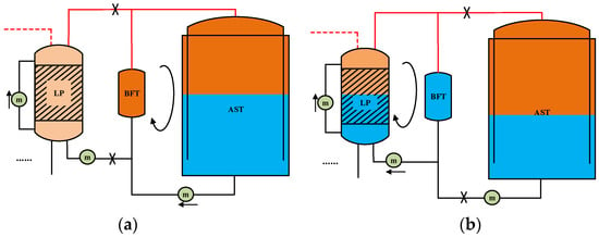
Figure 1.
Dual-mode operation process of BFT during energy storage: (a) CBA mode; (b) CBP mode.
The power generation cycle is the reverse of the energy storage cycle, also comprising two periods. The first period operates in CBP mode (Figure 2a), where the air is expanded in BFT and LP jointly. Liquid is pumped counterclockwise from the LP to the BFT, leaving the BFT fully filled with liquid. The second period operates in CBA mode (Figure 2b), where liquid is pumped counterclockwise from the BFT to the AST, while an equivalent volume of high-pressure air migrates from the AST to the BFT, achieving constant-pressure air charging. The LP independently expands air during this period. The cycle repeats until power generation concludes.
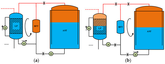
Figure 2.
Dual-mode operation process of BFT during power generation: (a) CBP mode; (b) CBA mode.
2.2. Dual-Mode Operation Strategy of Hydraulic Cylinders
To achieve the constant-pressure air storage process, the AST transfers liquid to the LP under the segmented operation strategy of the BFT during energy storage, while the liquid is reciprocally transferred from the LP back to the AST during power generation. To maintain a constant liquid volume in the liquid piston during energy storage and power generation, a hydraulic cylinder is employed to discharge excess liquid to a water storage tank (WST) or replenish deficient liquid. The hydraulic cylinder operates in two modes: CPP mode (combined LP and LP mode) and CPW mode (combined LP and WST mode). In CPP mode, the hydraulic cylinder connects two liquid pistons to facilitate gas compression/expansion. In CPW mode, it connects a liquid piston to the WST for liquid discharge or replenishment.
During energy storage cycle, the hydraulic cylinder first operates in CPP mode (Figure 3a), transferring liquid from LP1 to LP2 to compress low-pressure air by linear drive. Subsequently, it switches to CPW mode (Figure 3b) to discharge excess liquid to the WST.
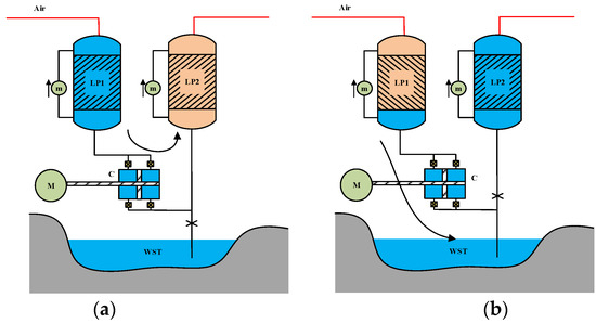
Figure 3.
Dual-mode operation process of hydraulic cylinder during energy storage: (a) CPP mode; (b) CPW mode.
During the power generation cycle, the hydraulic cylinder initially operates in CPW mode (Figure 4a) to replenish liquid from the WST to LP1, followed by CPP mode (Figure 4b) to enable air expansion-driven power generation.
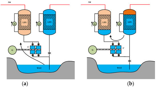
Figure 4.
Dual-mode operation process of hydraulic cylinder during power generation: (a) CPW mode; (b) CPP mode.
It is evident that when the pressure of low-pressure air entering LP1 is higher than the ambient atmosphere, the CPW mode during energy storage can generate electrical power, while the CPW mode during power generation will consume electrical power. This can lead to power backflow regardless of the energy storage and power generation processes. To avoid this situation, a solution involving the operation of two sets of hydraulic cylinders on the same rod can be adopted. One set of hydraulic cylinders operates according to the aforementioned strategy, while the other set of hydraulic cylinders is always connected between the two liquid pistons. The combined force generated by the two sets of hydraulic cylinders can maintain a constant direction, thereby reducing the complexity of motor control. The system model mentioned in the following section adopts the solution with two sets of hydraulic cylinders.
3. Constant-Pressure Isothermal Compressed Air Energy Storage System (CP-ICAES)
3.1. System Structure
Based on dual-mode operation strategies of the BFT and hydraulic cylinder, a constant-pressure isothermal compressed air energy storage (CP-ICAES) system can be constructed. As shown in Figure 5, the system adopts a two-stage compression configuration: the low-pressure stage employs a low-pressure compressor such as the screw compressor to realize the isothermal process, while the high-pressure stage utilizes a liquid piston compressor. Both stages are reversible, enabling operation as a low-pressure expander and a liquid piston expander, respectively. In the schematic, M1 denotes the drive motor of the low-pressure compressor, and M2 represents the linear motor of the liquid piston. G1 and G2 are the generators for the low-pressure expander and liquid piston linear generator, respectively.
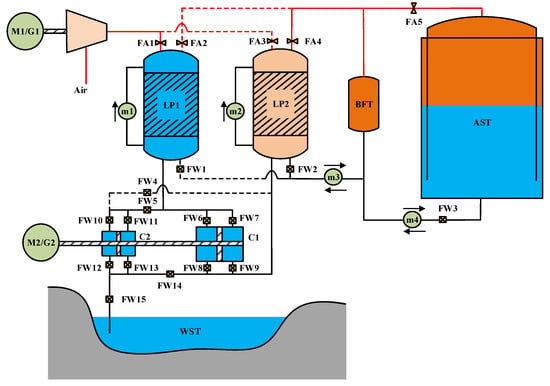
Figure 5.
Schematic of the CP-ICAES system.
The liquid piston compressor comprises the liquid piston, hydraulic cylinder, and reversible linear motors. The air is compressed or expanded into two liquid pistons, LP1 and LP2, alternately. Two hydraulic cylinders, C1 and C2, operate synchronously via pipelines and valves, facilitating bidirectional energy conversion between the liquid potential energy in the pistons and the electrical energy in the linear motors. Specifically, C1 exclusively transfers liquid between LP1 and LP2, while C2 manages liquid transfer between the LP and the WST. To maintain isothermal conditions during air compression/expansion, each liquid piston is equipped with a spray circuit. Auxiliary spray motors (m1, m2) pump water from the bottom to the top of the pistons, enabling rapid heat exchange between air and liquid.
In Figure 5, BFT means buffer tank, LP means liquid piston, AST means air storage tank, and WST means water storage tank. FA1~FA5 are air valves. FW1~FW15 are liquid valves. m1~m4 are auxiliary water pumps, where m1 and m2 are auxiliary spray water pumps for liquid pistons, and m3 and m4 are auxiliary migration water pumps for buffer tanks.
3.2. System Operation
3.2.1. Preconditioning Process
The system is initialized by LP1 filling with liquid, LP2 filling with low-pressure gas, BFT filling with high-pressure gas, and AST filling with liquid. Preconditioning ensures stable transitions during each cycle in the energy storage and power generation process, as shown in Figure 6. The preconditioning process can be realized through the following steps.
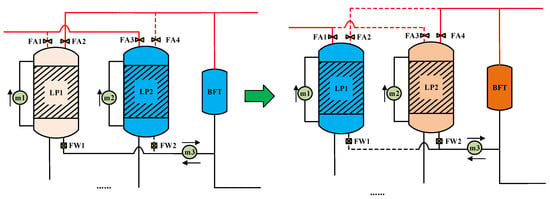
Figure 6.
Preconditioning process.
Step1: LP2, BFT, and AST are filled with liquid.
Step2: The low-pressure compressor injects ambient air into LP1 until the target pressure is achieved.
Step3: BFT operates in CBP mode, connected with LP1.
Step4: The hydraulic cylinder operates in CPW mode, transferring liquid from LP2 to LP1 via C1 while discharging excess liquid to WST through C2. Concurrently, LP2 receives low-pressure air from the screw compressor.
Step5: Once LP2 is emptied of liquid, LP1 is fully liquid-filled, and BFT contains high-pressure air. The preconditioning process ends.
After the preconditioning process, the system enters the energy storage process. When energy storage process is completed, only AST exhibits an increased air volume and a decreased liquid volume, while other components retain their preconditioned states, which is similar to the power generation process. Thus, subsequent cycles require no re-preconditioning, and its energy consumption is excluded from system efficiency calculations.
3.2.2. Energy Storage Process
In energy storage process, the low-pressure compressor M1 compresses ambient air into LP1. The liquid piston compressor, driven by linear motor M2, operates the hydraulic cylinder in CPP mode followed by CPW mode. Liquid is pumped from LP1 to LP2 to compress air, with excess liquid discharged to WST. BFT initially operates in CBA mode so as to store high-pressure air in AST via auxiliary pump m4. Once BFT is liquid-filled, it switches to CBP mode, transferring liquid to LP2 via pump m3. After compression, high-pressure gas is fully transferred to BFT from LP2, leaving LP2 liquid-filled and LP1 air-filled. LP1 and LP2 roles swap for the next cycle.
The valve open states of different modes during each cycle compression are shown in Table 1.

Table 1.
Valve open states of different modes during the energy storage process.
C1 and C2, as the transmission hydraulic cylinders that cooperate with the reciprocating operation of linear motor M2, need to open the corresponding valves according to the left and right movement process of the linear motor. The valve open states of hydraulic cylinders during energy storage process are shown in Table 2.

Table 2.
Valve open states of hydraulic cylinders during the energy storage process.
3.2.3. Power Generation Process
Before the power generation process, BFT contained high-pressure air, LP1 was liquid-filled, and LP2 held low-pressure air just like in the preconditioning state. First, BFT operates in CBP mode, expanding air jointly with LP1. The hydraulic cylinder operates in CPW mode followed by CPP mode, transferring liquid from LP1 to LP2 while replenishing water from WST. This reciprocating motion drives linear generator G2. Auxiliary pump m3 transfers liquid counterclockwise from LP2 to BFT. Once BFT is liquid-filled, it switches to CBA mode, transferring liquid to AST via pump m4 while high-pressure air returns to BFT. Meanwhile, the low-pressure air in LP2 expands through the low-pressure expander G1, generating electricity. After expansion, LP2 is liquid-filled, and LP1 is low-pressure-air-filled. The roles of LP1 and LP2 swap for the next cycle.
The valve open states of different modes during each cycle expansion are shown in Table 3.

Table 3.
Valve open states of different modes during the power generation process.
According to the left and right movement process of the linear generator, the valve open states of hydraulic cylinders during the energy storage process are shown in Table 4.

Table 4.
Valve open states of hydraulic cylinders during the power generation process.
4. Mathematical Model
The following assumptions are adopted for the mathematical analysis of the system:
- (1)
- The air is treated as an ideal gas.
- (2)
- The liquid is assumed incompressible, and air dissolution is negligible.
- (3)
- Kinetic energy losses, phase changes, and chemical reactions during gas–liquid flow are ignored.
- (4)
- Pressure losses in pipelines are neglected.
- (5)
- Valve switching time is excluded.
- (6)
- The linear motor operates at a constant speed during reciprocation, with no consideration of startup or shutdown processes.
4.1. Mathematical Model for Energy Storage Process
4.1.1. Low-Pressure Compressor
The low-pressure compressor delivers air alternately into two liquid pistons. With the aid of auxiliary spray pumps, the air fully interacts with the liquid, achieving a high heat transfer coefficient. Thus, the air outlet temperature approximates ambient conditions, and the compression process is considered isothermal. The theoretical work per unit mass for the low-pressure compressor is the following:
where is the mass inflow rate of air, and Rg is the air constant. T0, p1, and p0 represent ambient temperature, low-pressure gas pressure, and ambient pressure. Considering the efficiency of the low-pressure compressor , the actual unit power consumption is the following:
4.1.2. Liquid Piston Compressor
During the first cycle compression, liquid from LP1 is driven into LP2 by the linear motor M2 to compress air. To maintain optimal efficiency of the low-pressure compressor, the air pressure in LP1 needs to be constant [23]:
Under constant-pressure conditions in LP1, the volumetric inflow rate of air in LP1 equals the outflow rate of liquid:
where is the volumetric inflow rate of air to LP1, and is the outflow rate of liquid from LP1. Given that , where is the air density in LP1 and , can be expressed as follows:
The liquid driven by the linear motor enters LP2 or WST via hydraulic cylinders C1 and C2. The operating constant speed of the linear motor is vc, and the effective cross-sectional areas of C1 and C2 are S1 and S2, respectively. Regardless of the operating mode (CPP or CPW), the liquid outflow from LP1 satisfies the following:
For hydraulic cylinders with diameters D1, D2, and the piston rod diameters d1, d2, the effective areas are the following:
From Equation (4) to (8), the relationship between air mass flow rate and hydraulic cylinder dimensions is the following:
Let the cycle compression time be , and the liquid piston volume be VLP. The volume of LP satisfies the following:
During cycle compression, the hydraulic cylinders operate in CPP mode followed by CPW. The time of CPP mode is , and the time of CPW mode is , resulting in the following:
The liquid flow rate from LP1 to LP2 is , which is governed by C1 in CPW mode and by C1 and C2 jointly in CPP mode. can be calculated as follows:
Given that the initial pressure of LP2 is p1, the pressure in LP2 during cycle compression is the following:
The total liquid inflow to LP2 is , which comprises the liquid inflow from LP1 and BFT. represents the liquid inflow from LP1 through hydraulic cylinders, which is used to compress air. represents the liquid inflow from BFT, which is used to transfer liquid from AST, resulting in the following:
During cycle compression, the BFT operates in CBA mode followed by CBP. The time of CBA mode is , and the time of CBP mode is , resulting in the following:
The liquid inflow from BFT, , satisfies the following:
where is the operational flow rate of water pump m3.
The forces on hydraulic cylinders C1 and C2 during CPP and CPW modes are as follows:
The unit power consumption of linear motor M2 is the following:
Considering linear motor efficiency , the actual unit power consumption is the following:
Subsequent cycles involve role reversal between LP1 and LP2, with periodic repetition of air volume and pressure dynamics.
As auxiliary spray water pumps, m1 and m2 work inside a closed space, and their maximum working head is only the height value of LP, independent of air pressure. When the height of the LP is not considered, the impact of its power consumption can be ignored.
4.1.3. Buffer Tank
The BFT is initially filled with high-pressure air. Let the final pressure in LP2 be p2. The volume of BFT needs to satisfy the following:
In CBA and CBP modes, the liquid inflow rates to BFT are the following:
where and are the operational flow rates of water pumps m3 and m4. These satisfy the following:
Pumps m3 and m4 work inside a closed space, which is the same working condition as m1 and m2. So, the impact of its power consumption can be ignored when the height of the BFT and AST is not considered.
The pressure in BFT during cycle compression is the following:
4.1.4. Air Storage Tank
The AST operates at constant pressure. During the compression cycle, AST receives high-pressure air from BFT in CBA mode and remains unchanged in CBP mode. The storage pressure is the following:
The air inflow rate during cycle compression is the following:
4.2. Power Generation Process Modeling
4.2.1. Low-Pressure Expander
Low-pressure air from LP1 and LP2 alternately enters the low-pressure expander. With auxiliary spray water pumps enhancing heat transfer in LP, the temperature of the expanded air remains near ambient. The expansion process is considered isothermal. The unit work output of G1 is the following:
where is the mass outflow rate of air. Considering low-pressure expander efficiency , the actual unit power output is the following:
4.2.2. Liquid Piston Expander
During the first cycle expansion, liquid from LP1 enters LP2 via hydraulic cylinders, driving linear generator G2. To maintain optimal efficiency of the low-pressure expander, the air pressure in LP2 needs to be constant [23]:
Under constant-pressure conditions in LP2, the volumetric inflow rate of liquid in LP1 equals the outflow rate of air:
where is the volumetric outflow rate of air from LP2, and is the inflow rate of liquid to LP2. Similar to the compression cycle, can be expressed as follows:
For linear generator speed ve, the liquid inflow to LP2 via hydraulic cylinders C1 and C2 in CPP or CPW mode can be calculated as follows:
The relationship between mass outflow rate of air and hydraulic cylinder dimensions is the following:
Let the time of expansion cycle be . The liquid piston volume satisfies the following:
During cycle expansion, the hydraulic cylinders operate in CPW mode followed by CPP mode. The time of CPP mode is , and the time of CPW mode is , resulting in the following:
The liquid flow rate from LP1 to LP2 is , which is governed by C1 in CPW mode and by C1 and C2 jointly in CPP mode. can be calculated as follows:
Initially the air is expanded in LP1 and BFT jointly, with an internal pressure of p2 and volume of VBFT. The air pressure inside LP1 is the following:
The total liquid outflow from LP1 is , which comprises the liquid outflow to LP2 and BFT. represents the liquid outflow to LP2 through hydraulic cylinders, which is used to expand air. represents the liquid outflow to BFT, which is used to transfer liquid to AST, resulting in the following:
During cycle expansion, the BFT operates in CBP mode followed by CBA mode. The time of CBA mode is , and the time of CBP mode is , resulting in the following:
The liquid outflow to BFT, , satisfies the following:
where is the operational flow rate of water pump m3. The forces on hydraulic cylinders C1 and C2 during CPW and CPP modes are the following:
The unit power output of linear generator G2 is the following:
Considering linear motor efficiency , the actual unit power output is the following:
Subsequent cycles involve role reversal between LP1 and LP2, with periodic repetition of air volume and pressure dynamics. Similarly, the impact of power consumption in auxiliary spray water pumps can be ignored.
4.2.3. Buffer Tank
The BFT is initially filled with high-pressure air. The liquid inflow rates to BFT during CBP and CBA modes are the following:
where and are the operational flow rates of water pumps m3 and m4. These satisfy the following:
The pressure in BFT during cycle expansion is the following:
4.2.4. Air Storage Tank
The AST operates at constant pressure. It releases high-pressure air to BFT in CBA mode and remains unchanged in CBP mode. The storage pressure is as follows:
The air outflow rate during cycle expansion is the following:
4.3. Efficiency Analysis
Based on the models above, the efficiency of the CP-ICAES can be evaluated. Let the time of total energy storage be tc. The total energy consumption during energy storage is the following:
Let the time of total power generation be te. The total energy output during power generation is the following:
The efficiency of the system can be expressed as follows:
5. Case Study
5.1. Parameter Configuration
Based on the operational mechanism of CP-ICAES with dual-mode operation strategies of BFT and hydraulic cylinders, parameters are configured for an energy storage capacity of 100 kWh [22,29]. The key parameters for energy storage and power generation processes are listed in Table 5.

Table 5.
System parameter configuration.
The volume of LP listed above represents the effective volume. In practice, additional liquid must be retained to ensure cyclic spray requirements, resulting in a larger actual volume of LP.
5.2. Energy Storage Process
The total time of energy storage is 2 h, requiring four cycles under the condition of 0.5 h in each cycle compression. The low-pressure compressor compresses air from ambient pressure to 1 MPa and alternately delivers it to LP1 and LP2 at an intake flow rate of 0.203 kg/s.
Figure 7 illustrates the variation in liquid volume within the liquid pistons. During the first cycle, LP1 receives 1 MPa. To maintain constant pressure, the liquid outflow rate is 0.017 m3/s, fully draining within 0.5 h. Concurrently, the low-pressure air is compressed in LP2, initially matching LP1’s outflow rate in CPP mode. After 0.25 h, the hydraulic cylinders switch to CPW mode, reducing LP2’s inflow to 0.0102 m3/s. At this point, BFT exits CBA mode and enters CBP mode, supplementing LP2 with a migration flow of 0.0068 m3/s via pump m3. Thus, LP2 maintains a total inflow of 0.017 m3/s throughout the cycle. The volumes of liquid in LP1 and LP2 exhibit linear variations. The running time of different modes will have an impact on the liquid volume curve of LP.
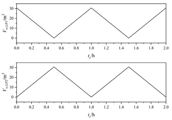
Figure 7.
Liquid volume variation in LP during energy storage process.
Figure 8 depicts the changes in air pressure in LP1 and LP2. In the first cycle, LP1 maintains a constant pressure of 1MPa. The air pressure in LP2 rises from 1 MPa to 5 MPa: C1 and C2 jointly compress air to 2 MPa during CPP mode (0~0.25 h); and the air pressure is increased gradually to 5 MPa in CPW mode (0.25~0.5 h). BFT’s mode transitions do not influence LP2’s pressure dynamics.
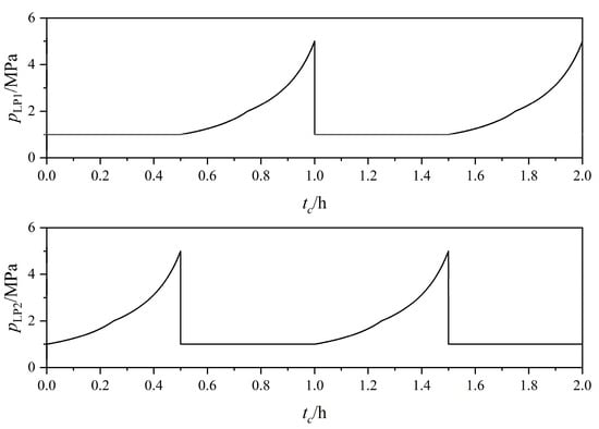
Figure 8.
Air pressure variation in LP during the energy storage process.
Figure 9 shows the air pressure and liquid volume dynamics of BFT. Initially filled with high-pressure air of 5 MPa, BFT operates in CBA mode, receiving liquid from AST until fully filled at 0.25 h. Switching to CBP mode, liquid drains into LP2 while pressure aligns with the rising pressure in LP2 (2~5 MPa).
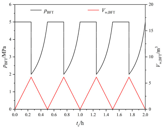
Figure 9.
Air pressure and liquid volume variation in BFT during the energy storage process.
Figure 10 presents AST’s air pressure and volume. Pressure remains constant at 5 MPa, with air volume increasing during CBA mode (inflow: 0.0068 m3/s) and stabilizing during CBP mode.
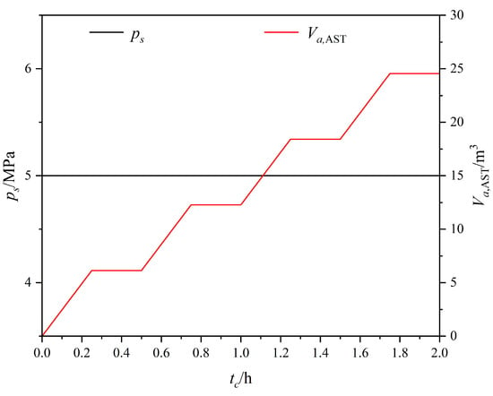
Figure 10.
Air pressure and volume variation in AST during energy storage.
Figure 11 displays the power curves of the system, including the power of the low-pressure compressor and the power of the liquid piston linear motor. The low-pressure compressor operates steadily at 46.2 kW with an efficiency of 85%. The linear motor exhibits periodic power fluctuations from 0 to 18.9 kW in CPP mode and from 4.5 to 38.7 kW in CPW mode with an efficiency of 90%. This is because the force on C2 is negative after mode switching, which can offset part of the driving force and reduce the power from 18.9 kW to 4.5 kW. In general, the power of the system fluctuates twice in the cycle. The total power consumption under CPP mode is 46.2~65.1 kW and that under CPW mode is 50.7~84.8 kW. The maximum power consumption of linear motor accounts for 45.6% of the system.
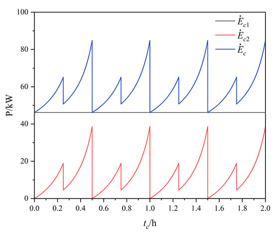
Figure 11.
Power curves of system during energy storage process.
The volume of stored air is 24.6 m3 at 5 MPa totally, equivalent to 100 kWh. The low-pressure compressor consumes 92.4 kWh of electricity, while the linear motor consumes 23.9 kWh, yielding a storage efficiency of 86.0%.
5.3. Power Generation Process
The total power generation time is 2 h, requiring four cycles under the condition of 0.5 h in each expansion cycle. The low pressure of 1 MPa from LP2 and LP1 undergoes isothermal expansion to ambient pressure at 0.203 kg/s.
Figure 12 illustrates liquid volume dynamics in LP. During the first cycle, the low-pressure air of 1 MPa inside LP2 is transferred to the low-pressure expander for expansion isothermally, and the liquid inflow is constant at 0.017 m3/s, fully filled at 0.5 h. BFT operates in CBP mode within the first 0.25 h and expands the air together with LP1. The liquid flow from LP1 to BFT is 0.0068 m3/s, while the hydraulic cylinder operates in CPW mode with the liquid flow of 0.0102 m3/s from LP1 to LP2 so that the total liquid outflow flow from LP1 is 0.017 m3/s. After 0.25 h, BFT operates in CBA mode with air expanded in LP1 independently, while the hydraulic cylinders switch to CPP mode with a liquid outflow of 0.017 m3/s. Hence, the liquid outflow of LP1 remains unchanged throughout the cycle. In each cycle, the volumes of liquid in LP1 and LP2 exhibit linear variations.
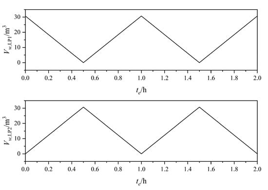
Figure 12.
Liquid volume variation in LP during the power generation process.
Figure 13 shows air pressure variation in LP. In the first cycle, LP2 maintains 1 MPa, while the air pressure of LP1 is decreased from 5 MPa to 2 MPa in CPW mode (0~0.25 h), dropping rapidly from 2 MPa to 1 MPa in CPP mode (0.25~0.5 h) because of C1 and C2 being driven jointly. Similarly, BFT’s mode transitions do not influence LP1’s pressure dynamics.
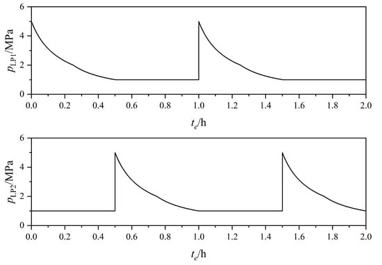
Figure 13.
Air pressure variation in LP during power generation.
Figure 14 depicts the air pressure and liquid volume dynamics of BFT. Initially filled with high-pressure air of 5 MPa, BFT operates in CBP mode, expanding air from 5 MPa to 2 MPa with LP1 jointly, so that the air pressure of BFT aligns with that in LP1. After 0.25 h, BFT filled with liquid switches to CBA mode, receiving high-pressure gas of 5 MPa from AST. The liquid of BFT is gradually drained.
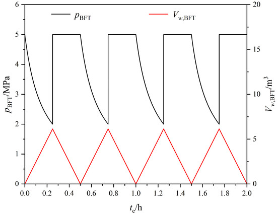
Figure 14.
Air pressure and liquid volume variation in BFT during the power generation process.
Figure 15 presents AST’s air pressure and volume. Pressure remains constant at 5 MPa, with air volume stabilizing during CBP mode and decreasing during CBA mode (outflow: 0.0068 m3/s).
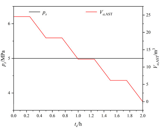
Figure 15.
Air pressure and volume variation in AST during power generation.
Figure 16 displays the power curves of the system, including the power of the low-pressure expander and the power of the liquid piston linear generator. The low-pressure expander operates steadily at 33.4 kW with an efficiency of 85%. The linear generator exhibits periodic power fluctuations from 31.3 kW to 3.7 kW in CPW mode and from 15.3 kW to 0 in CPP mode. This is because C1 and C2 act simultaneously to generate electricity after the mode switches, which increases part of the driving force and increases the power from 3.7 kW to 15.3 kW. In general, the power of the system fluctuates twice in the cycle. The total power output is 64.7~37.1 kW under CPW mode and 48.7~33.4 kW under CPP mode. The maximum power out of linear motor accounts for 48.4% of the system.
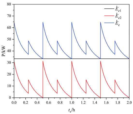
Figure 16.
Power curves of system during the power generation process.
The air consumption is 24.6 m3 at 5 MPa, equivalent to 100 kWh. All the air stored in the energy storage process is consumed in the power generation process, without the use of a throttle valve, which wastes the available energy of compressed air. The low-pressure expander generates 66.8 kWh of electricity, and the linear generator contributes 19.3 kWh, yielding a generation efficiency of 86.1%.
5.4. Efficiency Analysis
With compressor/expander efficiency at 85% and linear motor/generator efficiency at 90%, the total generated energy is 86.1 kWh, consuming 116.2 kWh, resulting in a system round-trip efficiency of 74.0%.
The efficiency of the system depends on the efficiencies of the low-pressure compressor/expander and liquid piston compressor/expander, as well as related to the pressure setting of low-pressure air p1. Generally speaking, due to the better isothermal effect of the liquid piston, the operating efficiency of liquid piston compressor/expander is higher than that of the low-pressure compressor/expander. With the increase in the low-pressure air’s pressure, the efficiency of the system will decline for the higher energy proportion of the low-pressure equipment. The greater the efficiency gap between the two parts, the more obvious the decline in system efficiency.
Figure 17 shows the system efficiency curve when the liquid piston efficiency is 90% and the low-pressure equipment efficiency is taken as 80%, 85%, and 90%, respectively. It can be seen that when the low-pressure equipment efficiency increases to 90%, consistent with the liquid piston efficiency, the system efficiency will not be affected by the low-pressure air pressure and will be stable at 81.0%. Figure 18 shows the system efficiency curve when the efficiency of low-pressure equipment is 85%, and the liquid piston efficiency is taken as 85%, 90%, and 95%, respectively. It can be seen that the liquid piston efficiency is reduced to 85%, which is consistent with the efficiency of low-pressure equipment. At this time, the system efficiency will not be affected by the low-pressure air pressure and will be stable at 72.3%.
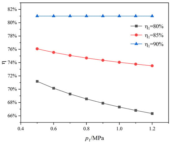
Figure 17.
Effect of low-pressure air pressure on system efficiency ( = 90%).
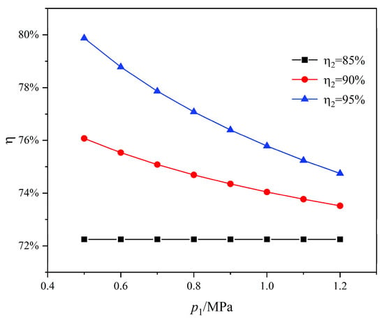
Figure 18.
Effect of low-pressure air pressure on system efficiency ( = 85%).
As the efficiency of low-pressure equipment and liquid piston equipment increases, the overall efficiency of the system will also increase, which can be seen from Figure 17 and Figure 18. For example, when the low-pressure air pressure is 1MPa, the system efficiency increases to 75.8% under the condition that the liquid piston equipment efficiency increases to 95%. And the system efficiency increases to 81% under the condition that the low-pressure equipment efficiency increases to 90%.
The efficiency analysis presented above is predicated on the idealized isothermal assumption, reflecting the system efficiency of 74.0% when the efficiency of low-pressure equipment and liquid piston equipment is 85% and 90%, respectively. However, for the near-isothermal CAES systems subject to temperature fluctuations, thermal efficiency degradation occurs as temperature control performance declines. Greater temperature fluctuation leads to lower thermal efficiency, which damages the overall system efficiency. As demonstrated in Table 6, which compares ideal CAES with near-isothermal CAES systems, with temperature fluctuations of 20 °C, cycle thermal efficiency diminishes to 87.2%, correspondingly depressing system efficiency to 64.6%.

Table 6.
Comparative analysis of efficiency between an ideal isothermal CAES system and a near-isothermal CAES system.
6. Conclusions
In order to achieve the operation process of constant-pressure storage in an ICAES system, dual-mode operation strategies of BFT and hydraulic cylinder were proposed. BFT is installed between the AST and LP, and the constant pressure inflow and outflow of high-pressure air in the air storage tank is achieved according to the CBA mode (combined BFT and AST mode), while the compression and expansion of air in the BFT and LP are jointly achieved according to the CBP mode (combined BFT and LP mode). This operation strategy ensures that the pressure in the AST is always constant and that the operation process of the liquid piston is not affected. The linear drive method adopts a hydraulic cylinder group, which compresses or expands the internal air of the dual liquid piston according to CPP mode (combined LP and LP mode) and discharges or replenishes the liquid caused by constant-pressure air storage according to CPW mode (combined LP and WST mode). This operation strategy ensures the normal operation of the liquid piston and achieves the release and replenishment of liquid under low pressure, reducing the work of liquid discharge and replenishment.
On the basis of the constant-pressure operation strategy above, a two-stage CP-CAES was constructed consisting of low-pressure equipment and liquid piston equipment. The low-pressure equipment adopts a screw compressor/expander that can achieve the isothermal process, and the high-pressure stage adopts a liquid piston compressor/expander driven linearly. In order to achieve continuous power operation of the liquid piston equipment without power backflow, two sets of hydraulic cylinders with different areas are used for linear drive. The preconditioning process, energy storage process, and power generation process analysis of the CP-CAES system were completed, and specific valve control strategies were provided as well. Based on the operational process, a mathematical model for CP-CAES was presented in this paper, including models for low-pressure equipment, liquid pistons, buffer tanks, and air storage tanks in energy storage and power generation processes, as well as models for efficiency calculations in energy storage and power generation.
The operation characteristics of various equipment in the system were simulated and analyzed based on a specific case study of CP-CAES with a capacity of 100 kWh, such as the air pressure and liquid volume variations in the liquid piston and buffer tank and the pressure and volume of high-pressure air in the air storage tank, as well as the power curves of low-pressure equipment and liquid piston equipment. When the low-pressure air is 1 MPa, the storage pressure is 5 MPa, and the compression time is set to 2 h, it is divided into four cycles, each cycle lasting 0.5 h. The pressure changes within the range of 2~5 MPa in BFT when the time of CBA mode is set to 0.25 h. The maximum power consumption proportion of the linear motor accounts for 45.6%, the maximum power output proportion of the linear generator accounts for 48.4% of the system, and the efficiency of the system can reach 74.0% when the efficiency of the low-pressure equipment and liquid piston equipment is 85% and 90%, respectively. As the efficiency of the equipment improved, the energy storage and power generation efficiency of the system was further enhanced. Generally, the efficiency of liquid pistons is higher than that of low-pressure equipment so that the system efficiency will be improved when reducing the pressure of low-pressure air. However, this also brings about the adverse effect of increasing the size of liquid pistons, which needs to be balanced.
The isothermal compressed air energy storage system based on a linear driven liquid piston can achieve a constant pressure storage operation on the basis of the dual-mode operation strategy of the buffer tank and hydraulic cylinder. This system is a new attempt in the field of isothermal compressed air energy storage to achieve a constant pressure storage process. The constant pressure operation process does not require the participation of additional high-pressure storage tanks, nor does it rely on the height of the mountain to set up constant-pressure compensation water columns. By simply setting up a buffer tank and two sets of liquid cylinders, the system can achieve continuous operation, greatly reducing the constant-pressure operation cost of the system. And due to the high efficiency and convenience brought by its own isothermal process, as well as the stability and high density of energy storage in the constant-pressure air storage process, it has broad application prospects in the future.
Author Contributions
Conceptualization, T.J. and Y.C.; methodology, Y.C.; validation, T.J.; formal analysis, Y.C.; investigation, Z.C.; resources, Z.C.; data curation, Z.C.; writing—original draft preparation, Y.C.; writing—review and editing, Z.C.; supervision, T.J. All authors have read and agreed to the published version of the manuscript.
Funding
This research received no external funding.
Data Availability Statement
Data are contained within the article.
Acknowledgments
The authors acknowledge the support of the State Key Laboratory of Alternate Electrical Power System with Renewable Energy Sources and the technical support of the Shanghai Investigation, Design and Research Institute.
Conflicts of Interest
The authors declare no conflicts of interest.
Abbreviations
| CAES | Compressed Air Energy Storage |
| ICAES | Isothermal Compressed Air Energy Storage |
| CP-ICAES BFT | Constant-Pressure Isothermal Compressed Air Energy Storage System Buffer Tank |
| LP | Liquid Piston |
| AST | Air Storage Tank |
| WST | Water Storage Tank |
| CBA | Combined BFT and AST |
| CBP | Combined BFT and LP |
| CPP | Combined LP and LP |
| CPW | Combined LP and WST |
| Symbols | |
| W | Work (kWh) |
| Mass Inflow Rate (kg/s) | |
| Rg | Air Constant (J/kg K) |
| T | Temperature (°C) |
| p | Pressure (MPa) |
| η | Efficiency (dimensionless) |
| V | Volume (m3) |
| ρ | Density (kg/m3) |
| v | Velocity (m/s) |
| S | Surface (mm2) |
| d | Diameter (mm) |
| E | Energy (kWh) |
| t | Time (h) |
| Q | Volumetric Flow Rate (m3/h) |
| F | Force (N) |
References
- Ahmad, T.; Zhang, D. A critical review of comparative global historical energy consumption and future demand: The story told so far. Energy Rep. 2020, 6, 1973–1991. [Google Scholar] [CrossRef]
- Bogdanov, D.; Ram, M.; Aghahosseini, A.; Gulagi, A.; Oyewo, A.S.; Child, M.; Caldera, U.; Sadovskaia, K.; Farfan, J.; De Souza Noel Simas Barbosa, L.; et al. Low-cost renewable electricity as the key driver of the global energy transition towards sustainability. Energy 2021, 227, 120467. [Google Scholar] [CrossRef]
- Downie, C. Strategies for Survival: The International Energy Agency’s response to a new world. Energ. Policy 2020, 141, 111452. [Google Scholar] [CrossRef]
- Bassam, A.M.; Elminshawy, N.A.S.; Oterkus, E.; Amin, I. Hybrid compressed air energy storage system and control strategy for a partially floating photovoltaic plant. Energy 2024, 313, 133706. [Google Scholar] [CrossRef]
- Chen, H.; Cong, T.N.; Yang, W.; Tan, C.; Li, Y.; Ding, Y. Progress in electrical energy storage system: A critical review. Prog. Nat. Sci. Mater. 2009, 19, 291–312. [Google Scholar] [CrossRef]
- Tong, Z.; Cheng, Z.; Tong, S. A review on the development of compressed air energy storage in China: Technical and economic challenges to commercialization. Renew. Sustain. Energy Rev. 2021, 135, 110178. [Google Scholar] [CrossRef]
- Chen, L.; Zhang, L.; Guo, W.; Lian, H.; Wang, Y.; Ye, K.; Xie, M. Dynamic analysis of an adiabatic compressed air energy storage system with temperature-regulated in air tanks. Renew. Sustain. Energy Rev. 2024, 206, 114862. [Google Scholar] [CrossRef]
- Li, H.; Dong, C.; Mao, Y.; Gu, H.; Ye, Y.; Ye, C.; Bu, Z.; Zhong, Y.; Ye, T. Performance discussion of a compressed air energy storage system based on compression and expansion dual-purpose compressor with water spray cooling function. J. Energy Storage 2024, 103, 114327. [Google Scholar] [CrossRef]
- Chen, L.; Zhang, L.; Yang, H.; Xie, M.; Ye, K. Dynamic simulation of a Re-compressed adiabatic compressed air energy storage (RA-CAES) system. Energy 2022, 261, 125351. [Google Scholar] [CrossRef]
- Dupin, V.; Teixeira, D. Advanced adiabatic compressed air energy storage systems dynamic modelling: Impact of the heat storage device. Heliyon 2025, 11, e40730. [Google Scholar] [CrossRef]
- Cui, J.; Yang, X.; Chen, J.; Su, H.; Xie, J. Multi-perspective analysis of adiabatic compressed air energy storage system with cascaded packed bed latent heat storage under variable conditions. Energy 2024, 305, 132373. [Google Scholar] [CrossRef]
- Ma, L.; Zhang, X.; Zhang, T.; Xue, X.; Chen, X.; Si, Y. Design and operation of an adiabatic compressed air energy storage system incorporating a detailed heat exchanger model. Energy 2024, 304, 132104. [Google Scholar] [CrossRef]
- PraveenKumar, S.; Kumar, A. Thermodynamic, environmental and economic analysis of solar photovoltaic panels using aluminium reflectors and latent heat storage units: An experimental investigation using passive cooling approach. Energy Storage 2025, 112, 115487. [Google Scholar] [CrossRef]
- Bennett, J.A.; Fitts, J.P.; Clarens, A.F. Compressed air energy storage capacity of offshore saline aquifers using isothermal cycling. Appl. Energy 2022, 325, 119830. [Google Scholar] [CrossRef]
- Cheekatamarla, P.K.; Kassaee, S.; Abu-Heiba, A.; Momen, A.M. Near isothermal compressed air energy storage system in residential and commercial buildings: Techno-economic analysis. Energy 2022, 251, 123963. [Google Scholar] [CrossRef]
- Heidari, M.; Mortazavi, M.; Rufer, A. Design, modeling and experimental validation of a novel finned reciprocating compressor for Isothermal Compressed Air Energy Storage applications. Energy 2017, 140, 1252–1266. [Google Scholar] [CrossRef]
- Zhang, X.; Xu, Y.; Zhou, X.; Zhang, Y.; Li, W.; Zuo, Z.; Guo, H.; Huang, Y.; Chen, H. A near-isothermal expander for isothermal compressed air energy storage system. Appl. Energy 2018, 225, 955–964. [Google Scholar] [CrossRef]
- Patil, V.C.; Ro, P.I. Modeling of liquid-piston based design for isothermal ocean compressed air energy storage system. Energy Storage 2020, 31, 101449. [Google Scholar] [CrossRef]
- Gouda, E.M.; Fan, Y.; Benaouicha, M.; Neu, T.; Luo, L. Review on Liquid Piston technology for compressed air energy storage. J. Energy Storage 2021, 43, 103111. [Google Scholar] [CrossRef]
- Patil, V.C.; Liu, J.; Ro, P.I. Efficiency improvement of liquid piston compressor using metal wire mesh for near-isothermal compressed air energy storage application. J. Energy Storage 2020, 28, 101226. [Google Scholar] [CrossRef]
- Chen, H.; Cheng, W.; Nian, Y. Liquid-gas heat transfer characteristics of near isothermal compressed air energy storage based on Spray Injection. Int. J. Heat Mass Tran. 2023, 215, 124530. [Google Scholar] [CrossRef]
- Li, R.; Tao, R.; Yao, E.; Chen, H.; Zhang, H.; Xu, X.; Wang, H. Comprehensive thermo-exploration of a near-isothermal compressed air energy storage system with a pre-compressing process and heat pump discharging. Energy 2023, 268, 126609. [Google Scholar] [CrossRef]
- Fu, H.; Jiang, T.; Cui, Y.; Li, B. Adaptive Hydraulic Potential Energy Transfer Technology and Its Application to Compressed Air Energy Storage. Energies 2018, 11, 1845. [Google Scholar] [CrossRef]
- Kim, Y.M.; Favrat, D. Energy and exergy analysis of a micro-compressed air energy storage and air cycle heating and cooling system. Energy 2010, 35, 213–220. [Google Scholar] [CrossRef]
- Cao, R.; Li, W.; Wang, S.; Yang, H.; Kuang, C. Comprehensive comparative study of two novel isobaric adiabatic compressed air energy storage systems coupled with pumped hydro storage. Appl. Therm. Eng. 2024, 257, 124318. [Google Scholar] [CrossRef]
- Wei, L.; Liu, X.; Wu, F.; Li, H.; Wu, Y.; Zhou, H. Performance analysis of a novel isobaric compressed air energy storage (CAES) system based on dual fluid. J. Energy Storage 2025, 108, 115001. [Google Scholar] [CrossRef]
- Wang, H.; Wang, L.; Wang, X.; Yao, E. A Novel Pumped Hydro Combined with Compressed Air Energy Storage System. Energies 2013, 6, 1554–1567. [Google Scholar] [CrossRef]
- Yao, E.; Wang, H.; Liu, L.; Xi, G. A Novel Constant-Pressure Pumped Hydro Combined with Compressed Air Energy Storage System. Energies 2015, 8, 154–171. [Google Scholar] [CrossRef]
- Kim, Y.M.; Shin, D.G.; Favrat, D. Operating characteristics of constant-pressure compressed air energy storage (CAES) system combined with pumped hydro storage based on energy and exergy analysis. Energy 2011, 36, 6220–6233. [Google Scholar] [CrossRef]
Disclaimer/Publisher’s Note: The statements, opinions and data contained in all publications are solely those of the individual author(s) and contributor(s) and not of MDPI and/or the editor(s). MDPI and/or the editor(s) disclaim responsibility for any injury to people or property resulting from any ideas, methods, instructions or products referred to in the content. |
© 2025 by the authors. Licensee MDPI, Basel, Switzerland. This article is an open access article distributed under the terms and conditions of the Creative Commons Attribution (CC BY) license (https://creativecommons.org/licenses/by/4.0/).