Abstract
Modular converters offer an effective solution for battery energy storage systems (BESSs) by lowering battery pack voltage levels and enabling additional functionalities, such as state of charge (SoC) and state of health (SoH) balancing, temperature regulation, and improved system reliability. However, conventional modular designs often require numerous additional components, including passive elements, switches, and sensing circuits. This paper proposes a modular multi-port converter (MMPC) BESS that combines energy conversion and battery management functions, leveraging the benefits of both modular and multi-port architectures. The proposed system demonstrates promising scalability and adaptability within the tested voltage and power ranges, with potential for extension to higher voltage and power applications through modular expansion. It also introduces an additional control layer, enhancing flexibility for control optimization and cost-effectiveness while improving reliability by reducing dependency on bypass switches. A prototype utilizing three dual-port converters managing six battery packs was developed. The experimental results confirm that the MMPC-based BESS achieves energy conversion and effectively balances the SoC among battery packs during both charging and discharging, under initial SoC mismatches.
1. Introduction
Battery energy storage systems (BESSs) are being deployed across a wide range of power levels to enhance grid performance, from small-scale applications in residential and distribution networks to large-scale utility projects. At the residential level, BESS units with capacities between 5 kWh and 10 kWh are commonly integrated with rooftop photovoltaic (PV) systems to support voltage regulation, reduce peak demand, improve self-consumption, enhance local reliability, and benefit from feed-in tariffs [1,2]. At the utility scale, several large-scale BESS projects have demonstrated their effectiveness in improving grid reliability and operational efficiency. For instance, the Hornsdale Power Reserve in Australia, with a capacity of 150 MW/194 MWh, has been shown to provide fast frequency response and reduce contingency reserve requirements [3]. The Leighton Buzzard Energy Storage project in the UK (6 MW/10 MWh) was one of the first grid-scale battery installations in Europe and demonstrated the feasibility of using BESSs for peak shaving and voltage control [4]. In the United States, the Notrees Wind Energy Storage Project (36 MW) integrates battery storage with wind generation to enhance grid stability and provide ancillary services such as frequency regulation [5]. The large scale deployment of BESSs across the power system from generation to distribution illustrate its role as a critical infrastructure component in modern power systems by supporting renewable energy integration, enhancing grid resiliency and self-consumption, reducing transmission losses, and improving overall power quality and system reliability [6,7].
One of the common configurations for connecting BESSs in a DC-coupled system, for example, with a photovoltaic (PV) source is shown in Figure 1. In such systems, the DC bus voltage typically operates within a range of 300 V to 600 V, while the nominal battery voltage generally varies from 100 V to 400 V, depending on the specific application and system design parameters [8]. Individual battery cell voltages generally range from 1 to 4.5 V, with nominal values depending on the cell chemistry; for example, approximately 1.25 V for Nickel Metal Hybrid (NiMH), 2 V for lead-acid, 2.1 V for sodium-sulfur (NaS), 3.6 V for nickel manganese cobalt (NMC), and 3.3 V for lithium iron phosphate (LiFePO4) cells [9,10]. To achieve the required voltage levels, multiple cells are connected in series to form a battery pack. However, mismatches between cells in battery packs are inevitable due to variations in intrinsic resistance, self-discharge rates, and capacity caused by manufacturing tolerances. Over repeated charge–discharge cycles, these mismatches are exacerbated by unequal power losses, thermal gradients, and external circuitry for sensing and protection. Since pack performance is limited by the weakest cell, early charge termination leads to underutilized capacity, while early discharge cutoff results in energy loss. In addition, the overcharging or deep discharging of individual cells accelerates degradation and poses safety risks [11]. To address these issues, battery management systems (BMSs) implement cell balancing for series connected cells.
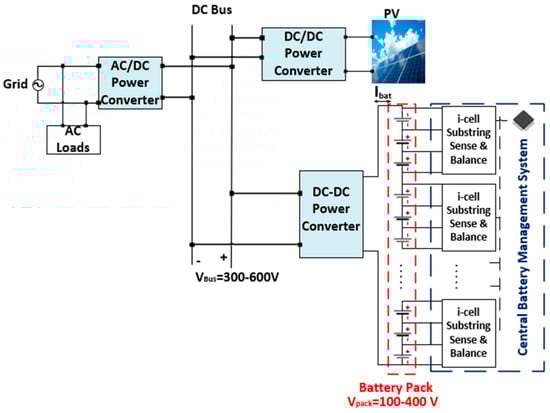
Figure 1.
Typical DC coupled PV-BESS System.
Several cell balancing topologies have been proposed in the literature. Dissipative balancing, shown in Figure 2, is the simplest and cheapest one, where surplus charges from higher-voltage cells are diverted through resistors, typically controlled by MOSFETs, and dissipated as heat [12]. However, the excess energy is dissipated as heat, resulting in a low energy efficiency. In addition, in practice, the balancing current is restricted to several mA to prevent excessive heat generation, and the resultant balancing speed is slow with this limited current, especially for higher power application.
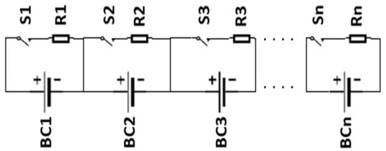
Figure 2.
Dissipative cell balancing methods.
In energy transfer methods, excessive energy is transferred from higher to lower charged cells through passive components like capacitors, inductors, or transformers. The switched capacitor (SC) balancing method, shown in Figure 3a, uses capacitors to redistribute charges between neighboring cells during switching operations, facilitating gradual voltage equalization. However, it is limited to adjacent-cell transfer, resulting in increased losses and balancing time as the cell string lengthens [13]. Variants such as double-tiered [14] and chain structures [15], as shown in Figure 3b,c, respectively, slightly improve performance by adding additional capacitors but still restrict transfer to neighboring cells. To overcome this, Ye et al. proposed an optimized SC method [16], shown in Figure 3d, enabling energy exchange between any cells through a shared capacitor connection point. Capacitor-based energy shuttling offers simple control, using only complementary switch signals without voltage sensing or closed-loop control [17]. However, these methods target voltage balancing rather than SoC, which leads to an increased imbalance from cell resistance variations and longer equalization times due to flat battery discharge curves [18]. The multi-inductor method proposed in [19], shown in Figure 3e, enables energy exchange between nearby cells. However, it suffers from increased losses and balancing time as the string length grows, similar to the SC method. To improve this, Park et al. proposed a single-inductor method [20] which transfers energy directly from the highest to the lowest charged cell by controlling specific switches. While this approach offers faster balancing, its efficiency is limited by the diode voltage drop in the path, which can account for 10–20% of a single cell’s voltage. Figure 3f illustrates the multi-winding energy transfer method which offers simple control by connecting the battery pack to a transformer’s primary winding and using one switch to induce currents in the secondary winding [21,22]. The battery cells with lower voltages receive higher currents, and therefore balancing is achieved with a simple control method. Although it achieves better efficiency and allows energy transfer from any cell to any cell, the design complexity of the multi-winding transformer increases with the number of string cells. The multiple-transformer equalization method is shown in Figure 3g [23]. It uses an individual transformer for each battery cell, with simple control via single switches. Each transformer’s primary winding connects to the battery pack via a single control switch, enabling simple control. The induced secondary current is inversely related to the battery’s SoC, so lower-SoC cells receive higher current due to their lower voltage. However, the method is limited by a high cost and bulky transformer size. The converter can also be used for an alternative energy-transferring based-charge balancing method. Figure 3h illustrates the Cuk converter configuration introduced in [24,25], which facilitates energy transfer between adjacent cells. As the number of cells in the series grows, this constraint leads to increased energy loss and a prolonged balancing time. Figure 3i illustrates the central converter approach described in [26,27], which uses selective switching to direct energy from the battery pack to individual cells. While this technique supports fast and effective balancing and benefits from requiring only one converter, it employs a number of switches proportional to the number of series-connected cells, limiting its efficiency and increasing control complexity for long battery strings. The available cell balancing topologies exhibit poor performance in long battery strings, with their effectiveness limited by the number of series-connected cells.
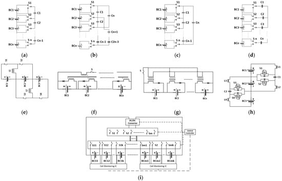
Figure 3.
Energy-transferring cell-balancing topologies: (a) SC, (b) Double-Tiered SC, (c) Chain Structure, (d) Optimized SC, (e) Multi-Inductor, (f) Multi-Winding Transformer, (g) Multiple Transformer, (h) Cuk Converter, (i) Single Converter for modularized cells.
Considering the limitations of conventional battery-cell-balancing methods, recent research has focused on distributed battery packs with converters to lower the voltage rating per pack and reduce BMS processing loads, thereby enabling additional pack level balancing. Tashakor et al. [28] proposed a modular multilevel topology consisting of cascaded double half-bridge modules interconnected by tightly matched coupled inductors, as shown in Figure 4a. It supports three operating modes, series, parallel, and bidirectional dc–dc buck-boost mode. This enables output voltage generation, load current sharing, and energy transfer between battery packs with varying voltages and characteristics. SOC balancing is achieved in real time during load operation by regulating intermodular circulating currents, allowing dynamic energy redistribution without a separate balancing phase. However, the reliance on precisely matched inductors introduces sensitivity to manufacturing tolerances, where even small mismatches may lead to uneven current sharing, increased EMI, and power losses. This dependency may pose challenges for large-scale implementation, potentially limiting the system’s scalability and robustness in practical applications. Farakhor et al. [29] proposed a reconfigurable battery energy storage system architecture, shown in Figure 4b, in which each battery cell is interfaced with a dedicated DC–DC converter, and reconfigurable switches define the series, parallel, or bypass configurations at the system level. In parallel configurations, the substantial voltage difference between individual cell or pack outputs and the DC bus necessitates an excessively high voltage conversion ratio, limiting its scalability for high-voltage applications. In [30], a multi-winding transformer was employed to interface low-voltage battery modules individually with the system, as shown in Figure 4c, enabling additional balancing capability across different battery packs. However, the complexity of designing a multi-winding transformer increases significantly with the number of modules, which limits the scalability of this approach. In addition, the use of a two-stage DC–AC–AC–DC conversion further reduces overall efficiency due to additional conversion losses. Figure 4d illustrates the two-stage power conversion architecture applied to an initially modular-connected BESS [31]. In this topology, low-voltage battery packs are interfaced through individual boost converters, which are subsequently connected to a secondary half-bridge stage. This secondary stage incorporates additional conversion functionalities such as buck, buck-boost, or bypass modes, thereby extending the system’s output voltage range. However, the need for large inductors and capacitors in the secondary stage contributes to increased system size and cost. Moreover, the two-stage conversion process introduces additional power losses, negatively impacting overall system efficiency. Figure 4e shows the modular BESS, which connects each low-voltage battery pack to its own DC–DC converter, with the outputs of these converters cascaded in series along the DC bus to increase the total voltage of the system [32,33]. This architecture facilitates the independent power management of individual battery packs, which has been leveraged for applications such as state-of-charge (SoC) balancing [33,34], state-of-health (SoH) balancing [35], and thermal management [36]. However, the modular BESS requires numerous auxiliary components, increasing complexity and cost. In the multi-port setup, a single high-power converter manages the energy from all battery packs, which are individually connected or disconnected using dedicated control switches [37,38,39]. Sun et al. [38] applied enable/disable switching mechanisms to achieve SoC balancing, whereas Karthikeyan et al. [37] used bypass paths to improve the light-load efficiency of the central converter. The multi-port design uses a single high-power converter, simplifying the architecture. However, the simultaneous bypass of many battery packs may be needed for SoC balancing, requiring a high voltage conversion ratio, which limits system scalability. Additionally, a fault in the central DC–DC converter results in total system failure due to its reliance on a single high-power converter.
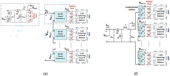
Figure 4.
Modularized battery packs/cell: (a) modular multilevel-series/parallel-converter-based BESS, (b) Modular Reconfigurable BESS, (c) Multi-Transformer-based BESS, (d) boost-multilevel converter-based BESS, (e) modular BESS, (f) multi-port-converter-based BESS.
The MMPC-based BESS proposed in this paper reduces the number of components and sensing circuits compared to the modular system. In conventional modular BESS architectures, each DC–DC converter operates with high-frequency PWM control, which increases the overall system complexity, cost, and control burden. In contrast, the proposed MMPC-based BESS reduces the total number of required converters by allowing each multi-port converter to interface with multiple battery packs. While the proposed MMPC-based BESS still requires PWM control for the main converter operation, it simplifies the overall control structure by centralizing the management of enable/disable and bypass switches, which operate in basic on/off mode. These switches are not part of the high-frequency switching loop and only act during mode changes or fault isolation, significantly reducing the control and timing demands on the system. It also eliminates the need for the high voltage conversion ratio of the multi-port system by using series-converter modules in a similar way to the modular system. The system voltage requirement can be achieved by configuring multiple multi-port converters in series, while the desired capacity can be met by adding modules in parallel. While the energy management system (EMS) oversees power distribution among multiple parallel-connected MMPC-based BESS units, an internal power-sharing mechanism is also implemented within each individual MMPC-based BESS. Controlling individual battery packs enables the implementation of advanced control strategies based on parameters such as SoC, SoH, and temperature. For instance, the temperature of each pack can be regulated by adjusting the power output of its associated modules and selectively enabling or disabling specific packs. When the temperature of a particular battery pack exceeds a safe threshold, it can be temporarily bypassed from the system until its temperature returns to an acceptable level. This paper employs an SoC-based power sharing algorithm within the proposed MMPC-based BESS architecture, which enables simultaneous SoC balancing and power conversion. Pack level balancing is achieved by bypassing individual battery packs, while module level balancing is achieved by controlling individual multi-port converter modules’ power. The reliability of the proposed structure is also analyzed against both counterpaths, i.e., modular and multi-port-converter-based BESSs, for varying numbers of ports and converters.
This paper is organized as follows. Section 2 presents the proposed MMPC-based BESS, its operating modes, and the SoC-based power sharing control strategy. Section 3 compares proposed topology to the modular and multi-port-converter-based BESSs in terms of component numbers, their ratings, and the overall reliability. Section 4 experimentally verifies its power sharing capability in discharging and charging modes. Finally, Section 5 presents the conclusion.
2. Proposed Modular-Multi-Port-Converter-Based BESS
2.1. System Description
The circuit diagram of the proposed MMPC-based BESS is shown in Figure 5. A multi-port DC–DC converter with m ports is used for a group of m battery packs. Multiple m-port converters (k converters) are connected in series on the DC bus side to provide a higher DC link voltage and eliminate the need for a high voltage conversion ratio converter. Each low-voltage battery pack has its own BMS and balancing circuits, which perform better BMS functionalities due to the reduced number of series-connected cells. Each battery pack (pack xy) is connected to its associated m-port converter via complementarily operated enable/disable switches, Sxy and Sxy’, for battery module x (from 1-k) and port y (from 1-m), respectively. These switches control the connection and disconnection of the corresponding battery packs. The local BMS autonomously monitors cell conditions and overall pack health. In case of a fault, such as in battery pack 11, the BMS isolates the affected unit via integrated back-to-back (B2B) switches. Specifically, the disable switch (S11) is turned on while the enable switch (S11′) is turned off, effectively bypassing the faulty pack. This localized isolation allows the remaining battery packs on the same converter to continue operation uninterrupted.
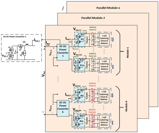
Figure 5.
The proposed MMPC-based BESS.
Equivalent circuits for a two-port converter under different operating modes are shown in Figure 6. To connect a battery pack (e.g., BP1), switch S11 is turned on while the disable switch (S11’) is turned off, and vice versa. Figure 6a,b show the equivalent circuits when no battery packs are bypassed and when BP1 is bypassed, respectively. Switches S3 and S4 of each two-port converter module manage the connection or bypassing of the entire module, as illustrated in Figure 6c.
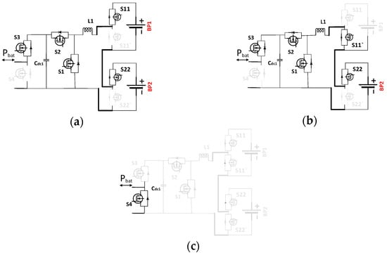
Figure 6.
The equivalent circuit of module 1 (a) when there is no bypassed battery pack, (b) when battery pack 1 is bypassed, and (c) when complete module 1 is bypassed.
2.2. Proposed Power Sharing Controller for the MMPC-Based BESS
An SoC-based power sharing controller is proposed for the MMPC-based BESS. Module-level balancing is achieved by adjusting the power output of individual k multi-port converters. During discharging, modules with a higher SoC are assigned higher power outputs, while those with a lower SoC contribute less, promoting SoC equalization across modules. Since all converters are connected in series on the DC bus side, the same current flows through each converter. Therefore, power differences are realized by varying the output voltages of individual converters. To do this, the average SoC of all modules from to is compared to the overall system average SoC (). A proportional controller then generates voltage correction terms for all modules from to to adjust its DC bus-side reference voltage accordingly, as shown in Figure 7a. Bypassed battery packs are excluded from the modules’ average SoC calculation to ensure a decoupled control strategy. As pack level balancing is independently handled within each module, the controller focuses on module-level balancing. The DC bus side voltage of each module is scaled in proportion to its total battery voltage, allowing discharging power to be distributed according to the SoC of the active modules. To ensure the overall DC bus voltage remains constant, the sum of the voltage correction values, , is subtracted from the individual reference voltages. The DC bus voltage of module-x is calculated as follows:
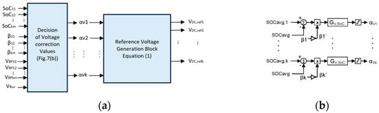
Figure 7.
Power sharing controller among different modules: (a) generation of voltage correction values; (b) decision of individual modules reference voltage.
Pack-level balancing is performed via a bypassing mechanism, as illustrated in Figure 8. Battery packs within a module are sorted based on their SoC, and the mismatch between the highest and lowest values is evaluated. If the mismatch exceeds a predefined threshold, the pack with the lowest SoC is bypassed during discharge. This threshold can be selected based on the system’s acceptable SoC deviation limit.
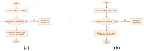
Figure 8.
Pack-level balancing algorithm: (a) discharging mode; (b) charging mode.
In the charging mode, modules with a higher SoC are assigned lower power inputs, while those with a lower SoC are charged with higher power to achieve module-level balancing. During charging mode operation, the DC bus voltage of module-x is calculated using (2). The battery packs with the highest SoC need to be bypassed in this mode, as shown in Figure 8b.
3. Comparison
As depicted in Figure 9, three converter architectures are compared for a system with n battery packs, where the modular BESS employs n single-port converters (m = 1), while the multi-port-converter-based BESS uses a single converter with m = n ports. The proposed MMPC-based BESS lies between the modular and multi-port-converter-based BESSs.
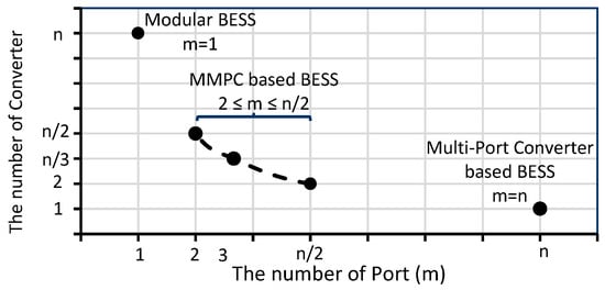
Figure 9.
The number of converters with respect to number of ports.
3.1. Number of Components and Their Ratings
The required number of switches and passive elements varies based on the specific converter configuration and the design of the bypass mechanism. This analysis considers a bi-directional half-bridge buck-boost converter for all configurations, incorporating two complementary switches for the bypassing function. The comparison is based on a fixed number of battery packs, each with identical capacity. Table 1 summarizes the converters based on component count and ratings for n battery packs. Considering a distribution grid, an example with 15 battery packs is provided, where the DC bus voltage is 400 V, and each battery pack has a rated voltage of 12.8 V and a capacity of 25 Ah.

Table 1.
Component count and rating for three considered topologies.
Among the three topologies, the modular BESS contains the most components but benefits from the lowest voltage requirements. In modular systems, the switches and DC bus capacitors must be rated at a minimum of (, where () stands for the additional balancing voltage. It requires capacitors, voltage sensing circuits, and inductors and current sensing circuits, all of which contribute to increased system expense. In the multi-port architecture, only switches, a single inductor, and two capacitors are used; however, these components must be rated to withstand the full DC bus voltage. The inductor must be physically larger for the same current ripple due to higher terminal voltage. Despite the reduced number of components, the central high-power converter requires bulkier and higher-rated elements, which enlarges the system footprint. Unlike modular BESSs, which scale by adding modules to raise voltage, multi-port-converter-based BESS scalability is limited by the need for all components to withstand full DC bus voltage. The proposed MMPC-based BESS offers a flexible topology between modular and multi-port-converter-based BESS designs. It uses fewer components than modular BESSs and has lower voltage ratings than multi-port-converter-based BESSs. For battery packs, n/m m-port converters are needed with four switches used for power conversion and bypassing in each converter, and two switches used to connect and disconnect each battery pack. Thus, the total number of switches is . Bypass and converter switch voltage ratings are and , respectively. The system requires inductors and current sensors, and capacitors and voltage sensors. It uses fewer inductors than modular BESSs and a lower inductance than multi-port-converter-based BESSs for the same current ripple. Inductors, converter switches, and enable/disable switches share current ratings equal to the maximum charging/discharging currents of the battery packs () in all structures. In both the modular BESS and MMPC-based BESS, the bypass arrangement switches have a current rating equal to the DC link current ().
3.2. Reliability
Reliability refers to a component’s or system’s ability to perform its functions over a specific period. BESS reliability is crucial and is estimated using reliability block diagrams, considering different numbers of battery packs. Submodule reliability is determined based on assumed component failure rates. The failure rate and reliability (R) for a component or system can be calculated as follows:
where and represent failure rate and quality factor, respectively, and is the number of the component.
In this paper, the failure rates in [40] are adopted for subsequent reliability evaluations. The hourly failure rates for each component are summarized in Table 2. The reliabilities of the battery, bidirectional DC–DC converter, and bypass circuitry are calculated over a 50,000 h operational period, which is a common period for power electronic components [40], using (4), under the assumption of a quality factor equal to unity. The resulting reliability estimates for these components are also presented in Table 2. Following the determination of individual components and submodule reliabilities, system-level reliability is assessed using reliability block diagrams. Equations (5) and (6) are employed to model series and parallel subsystem configurations, respectively.
Table 2.
The failure rate and reliability of each component.
To assess the reliability of each system configuration, corresponding reliability block diagrams are constructed and illustrated in Figure 10. In these diagrams, , , and are the reliabilities of the battery, bi-directional DC–DC converter, and bypass arrangements, respectively. In all configurations, the battery packs are independently integrated into the system and can be selectively bypassed during abnormal operating conditions via control of the bypass switches. Consequently, battery packs are modeled as parallel components, while their respective bypass arrangements are represented in series within the reliability block diagrams. In contrast to the modular BESS and MMPC-based BESS architectures, the multi-port-converter-based BESS depends on a single centralized converter, making its reliability a critical factor. The reliability functions for the modular BESS, multi-port-converter-based BESS, and MMPC-based BESS with n battery packs are derived using (5) and (6), and are explicitly given by (7), (8), and (9), respectively. Reliability analyses are performed for varying numbers of battery packs, as well as different numbers of converter ports in the MMPC-based BESS. The comparative reliability results for each architecture under these varying conditions are presented in Figure 11.
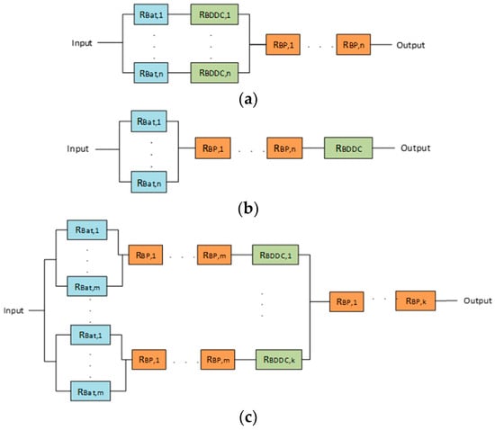
Figure 10.
Reliability block diagrams: (a) modular BESS, (b) multi-port-converter-based BESS, (c) MMPC-based BESS.
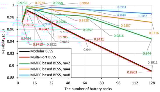
Figure 11.
Reliability of each structure with varying numbers of battery packs and multi-port converter ports.
The expression denotes the reliability of the battery. As the number of battery modules increases, the overall battery reliability improves due to their parallel configuration. For both the modular BESS and the multi-port-converter-based BESS, system-level reliability reaches its maximum when eight battery modules are employed. However, increasing the number of battery modules also increases the number of series-connected bypass circuits, which in turn reduces the overall system reliability despite the improvement in battery reliability. When the number of battery packs is small, the reliability of the bypass arrangement is relatively high due to low number of bypass arrangement circuits; however, the overall battery reliability remains low. In contrast, the proposed MMPC-based BESS incorporates fewer series-connected bypass circuits, represented by (), thereby achieving superior system reliability, particularly as the number of battery modules increases. The reliability performance of the MMPC-based BESS was evaluated for converter configurations with two, four, and eight ports. As illustrated in Figure 11, the two-port configuration exhibits a more rapid decline in reliability compared to the four-port and eight-port configurations. This highlights that minimizing dependency on series-connected bypass circuitry significantly enhances system reliability, especially in configurations with a large number of ports and battery modules. Furthermore, the architecture of the MMPC-based BESS facilitates integration with varying voltage levels while utilizing low-voltage battery packs, thereby improving both adaptability and operational robustness.
4. Experimental Results
To verify the power sharing capability of MMPC-based BESS developed in this paper, an experimental prototype comprising six LiFePo4 packs (Shenzhen, China) and three dual-port converters was built. Figure 12 shows the experimental setup. The experimental results for the modular BESS configuration utilizing six designed single-port converters are also presented. In MMPC-based BESS, each designed dual-port DC–DC converter is responsible for two battery packs, each rated at 12.8 V and 10 Ah. The control method was realized in a TMS320F28377d Texas Instrument digital signal processor (Dallas, TX, USA). The system was tested in both charging and discharging modes with initial SoC mismatches to prove the SoC balancing ability. The initial SoCs of each battery pack and the charging/discharging currents are summarized in Table 3.
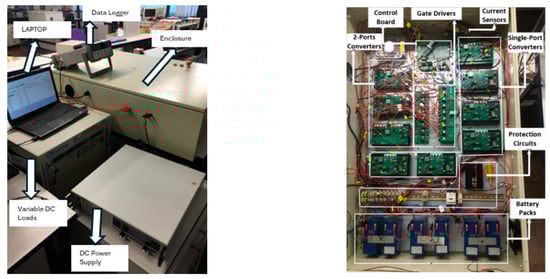
Figure 12.
Experimental prototype of MMPC-based BESS.
Table 3.
Experimental parameters.
4.1. Discharging Mode
In discharging mode, the primary objectives of the controller are to regulate the DC bus voltage and ensure SoC balancing among the battery packs. The results for the modular BESS are presented in Figure 13a,c. The SoC-based power sharing controller, as described in [34], is implemented in this study. Based on the individual SoC values of the battery packs, each converter delivers a different discharging power. Battery pack 2 provides the highest power, while battery pack 1 contributes the least. These power differences are achieved by adjusting the DC bus side voltage of each module, as shown in Figure 13a. Figure 13c shows the SoC profile of each battery pack. At approximately 57 min, all SoC values converge. When all battery packs are balanced, they discharge with equal current, as in Figure 13b, and their DC bus side voltages also become equal, as shown in Figure 13a.
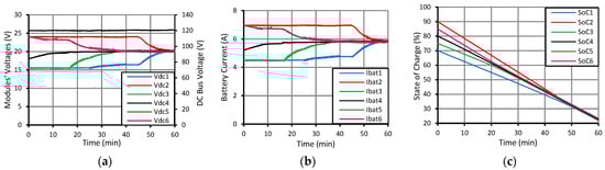
Figure 13.
Experimental results of modular BESS in discharging mode: (a) module’s DC bus side voltages; (b) charging current of each battery pack; (c) SoC of each battery pack.
A two-level decoupled SoC balancing strategy is employed for the MMPC-based BESS, where module-level balancing is achieved through the power sharing controller, while pack-level balancing is realized by selectively bypassing individual battery packs within each dual-port converter module. During the experiment, each battery pack is discharged at approximately 58% of its rated capacity, corresponding to an average discharge current of 5.8 A. The experimental setup and initial SoC values for each battery pack are summarized in Table 3. The configuration includes three modules: packs 1–2 (module 1), packs 3–4 (module 2), and packs 5–6 (module 3), each connected to a dedicated dual-port converter. Any SoC imbalance within a module is addressed through bypass control. The experimental results for the MMPC-based BESS using the two-level SoC-based power sharing controller are presented in Figure 14. At the beginning of the test, battery pack 1 is bypassed to equalize the SoC between packs 1 and 2. This results in a lower DC bus voltage for module 1, as shown in Figure 14a, due to the voltage drop caused by the bypassed pack. Consequently, pack 2, having the highest SoC, experiences the highest discharge current, as illustrated in Figure 14b,c. The significant current differences accelerate the balancing process. When the SoC of packs 1 and 2 converges at approximately 15 min, pack 1 is activated, and pack 3 is bypassed to balance packs 3 and 4. At approximately 19 min, once the SoC of battery packs 3 and 4 is equalized, pack 3 is activated, and the DC bus voltage of each module is subsequently adjusted to preserve overall module-level SoC balance. All modules reach SoC equilibrium by approximately 55 min, as shown in Figure 14c, resulting in uniform power sharing across all modules. Throughout the discharging process, the DC bus voltage is consistently regulated at 120 V, as depicted in Figure 14a. The two-level SoC balancing controller slightly reduces the overall balancing time compared to the modular BESS power sharing controller, as the bypassing mechanism further increases the power difference among battery packs, accelerating the balancing process.
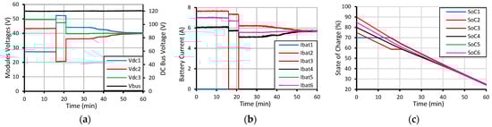
Figure 14.
Experimental results of MMPC-based BESS in discharging mode: (a) module’s DC bus side voltages; (b) charging current of each battery pack; (c) SoC of each battery pack.
4.2. Charging Mode
In charging mode, the modular and MMPC-based BESS are charged by applying a 120 V DC power supply to the DC bus, giving a 3A average charging current. The initial SoC of each battery pack is shown in Table 3. Figure 15a,c show the experimental results of the MMPC-based BESS with the two-level SoC-based power sharing controller in charging mode. Contrary to the discharging case, the battery pack with a higher SoC value than an average SoC value is charged with lower power, and vice versa. Battery pack 5 is charged with the higher current, while the charging current for battery pack 4 is the lowest, as shown in Figure 15b. At approximately 78 min, all SoC values converge, as shown in Figure 15c. The module’s DC bus side voltages are equal (Figure 15a), and they are charged with an equal current, which is shown in Figure 15b.
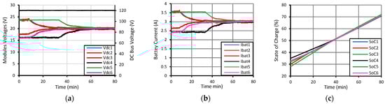
Figure 15.
Experimental results of modular BESS in charging mode: (a) module’s DC bus side voltages; (b) charging current of each battery pack; (c) SoC of each battery pack.
Figure 16a,c show the experimental results of the MMPC-based BESS with the two-level SoC-based power sharing controller in charging mode. The pack level balancing is used for battery packs 3 and 4, and 5 and 6. In charging mode, the battery pack with the higher SoC is temporarily bypassed to enable SoC equalization among the battery packs connected to the same multi-port converters. Thus, battery pack 6 is bypassed initially to balance battery packs 5 and 6 until around 9 min. The total battery power is shared among the modules based on the module’s average SoC () to perform module-level SoC balancing among the battery modules connected to different multi-port converters. Module 1 exhibits the highest DC bus voltage during this period, owing to its lower average SoC compared to module 2, as shown in Figure 16a. Conversely, module 3 shows the lowest DC bus voltage due to the bypassing of pack 6. Despite the lower bus voltage, module 3 receives a higher charging current, as its average SoC is the lowest among all modules ), as shown in Figure 16b. Subsequently, battery pack 4 is bypassed to balance battery packs 3 and 4 when the SoCs of battery packs 5 and 6 are equalized at around 9 min. The DC bus side voltages of each module are regulated accordingly to perform module-level balancing after following each bypassing/activation event. After 15 min, all battery packs are active, and module-level SoC balancing continues among the three modules. As shown in Figure 16c, complete SoC balancing across all modules is achieved at approximately 70 min, after which all modules are charged uniformly with equal current.
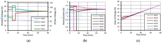
Figure 16.
Experimental results of MMPC-based BESS in charging mode: (a) module’s DC bus side voltages; (b) charging current of each battery pack; (c) SoC of each battery pack.
5. Conclusions
This paper proposed an MMPC-based BESS that combines the battery management functionalities of the modular and multi-port-converter-based BESS architectures, enhancing scalability without compromising battery pack performance. The proposed system achieves greater reliability than traditional designs by reducing reliance on bypass circuitry, particularly in configurations with a large number of modules, making it a promising topology for high-voltage applications such as integrating the BESS into medium voltage power networks. In addition, the number of ports and converters can be optimized for specific system requirements in terms of voltage ratings, size, cost, and reliability. The two-level SoC balancing capability of the MMPC-based BESS was experimentally validated using three dual-port converters managing six Li-ion battery packs. The results confirmed enhanced control functionality, enabling both module-level and pack-level power control.
Author Contributions
Methodology, software, writing—original draft preparation, B.Y.; supervision, writing—review and editing, M.A.E. and A.S.; review and editing, M.C.K. and B.A. All authors have read and agreed to the published version of the manuscript.
Funding
This research received no external funding.
Data Availability Statement
The original contributions presented in this study are included in the article. Further inquiries can be directed to the corresponding author.
Conflicts of Interest
The authors declare no conflicts of interest.
Abbreviations and Symbols
The following abbreviations and symbols are used in this manuscript:
| Abbreviations | |
| BESS | Battery energy storage system |
| BMS | Battery management system |
| SoC | State of charge |
| B2B | Back-to-back |
| SoH | State of health |
| MMPC | Modular multi-port converter |
| PV | Photovoltaic |
| SC | Switched capacitor |
| DC–DC | Direct Current–Direct Current |
| NaS | Sodium sulfur |
| NMC | Nickel manganese cobalt |
| NiMH | Nickel metal hybrid |
| LiFePO4 | Lithium iron phosphate |
| List of Symbols | |
| Vbat,x | Active battery packs’ voltage inside module-x |
| Vbat,tot | System total battery pack voltages |
| VDC,x | DC bus side voltage of module-x |
| VDC,refx | Reference DC bus side voltage of module-x |
| VBus | DC bus voltage |
| SoCavg,x | Average SoC of active battery packs inside module-x |
| SoCavg | System overall average SoC |
| n | Number of converters |
| m | Number of ports |
| αV | Voltage correction value |
| β | Bypass command |
| Pmax | Maximum power |
| Vbal | Balancing voltage |
| Ibat | Battery current |
| N | Number of components |
| ΠQ | Nickel manganese cobalt |
| λG | Failure rate |
| R | Reliability |
References
- Merrington, S.; Khezri, R.; Mahmoudi, A. Optimal sizing of grid-connected rooftop photovoltaic and battery energy storage for houses with electric vehicle. IET Smart Grid 2023, 6, 297–311. [Google Scholar] [CrossRef]
- Li, Y.; Li, H.; Miao, R.; Qi, H.; Zhang, Y. Energy–Environment–Economy (3E) Analysis of the Performance of Introducing Photovoltaic and Energy Storage Systems into Residential Buildings: A Case Study in Shenzhen, China. Sustainability 2023, 15, 9007. [Google Scholar] [CrossRef]
- Alcaide-Godinez, I.; Bai, F.; Saha, T.K.; Memisevic, R. Contingency Reserve Evaluation for Fast Frequency Response of Multiple Battery Energy Storage Systems in a Large-scale Power Grid. CSEE J. Power Energy Syst. 2023, 9, 873–883. [Google Scholar] [CrossRef]
- Mohamed, A.A.R.; Best, R.J.; Liu, X.; Morrow, D.J.; Pollock, J.; Cupples, A. Stacking Battery Energy Storage Revenues in Future Distribution Networks. IEEE Access 2022, 10, 35026–35039. [Google Scholar] [CrossRef]
- Wehner, J.; Mohler, D.; Gibson, S.; Clanin, J.; Faris, D.; Hooker, K.; Rowand, M. Technology Performance Report: Duke Energy Notrees Wind Storage Demonstration Project; Duke Energy Renewables: Charlotte, NC, USA, 2015. [Google Scholar]
- Trivić, B.; Savić, A. Optimal Allocation and Sizing of BESS in a Distribution Network with High PV Production Using NSGA-II and LP Optimization Methods. Energies 2025, 18, 1076. [Google Scholar] [CrossRef]
- Sasi Bhushan, M.A.; Sudhakaran, M.; Dasarathan, S.; Mariappane, E. Integration of a Heterogeneous Battery Energy Storage System into the Puducherry Smart Grid with Time-Varying Loads. Energies 2025, 18, 428. [Google Scholar] [CrossRef]
- Rauf, A.M.; Abdel-Monem, M.; Geury, T.; Hegazy, O. A Review on Multilevel Converters for Efficient Integration of Battery Systems in Stationary Applications. Energies 2023, 16, 4133. [Google Scholar] [CrossRef]
- Wu, G.; Lu, R.; Zhu, C.; Chan, C.C. State of charge Estimation for NiMH Battery based on electromotive force method. In Proceedings of the 2008 IEEE Vehicle Power and Propulsion Conference, Harbin, China, 3–5 September 2008; pp. 1–5. [Google Scholar] [CrossRef]
- Thingvad, M.; Calearo, L.; Thingvad, A.; Viskinde, R.; Marinelli, M. Characterization of NMC Lithium-ion Battery Degradation for Improved Online State Estimation. In Proceedings of the 2020 55th International Universities Power Engineering Conference (UPEC), Turin, Italy, 1–4 September 2020; pp. 1–6. [Google Scholar] [CrossRef]
- Wan, G.; Zhang, Q.; Li, M.; Li, S.; Fu, Z.; Liu, J.; Li, G. Improved Battery Balancing Control Strategy for Reconfigurable Converter Systems. Energies 2023, 16, 5619. [Google Scholar] [CrossRef]
- Song, H.; Chen, H.; Wang, Y.; Sun, X.-E. An Overview About Second-Life Battery Utilization for Energy Storage: Key Challenges and Solutions. Energies 2024, 17, 6163. [Google Scholar] [CrossRef]
- Wang, Y.; Yin, H.; Han, S.; Alsabbagh, A.; Ma, C. A novel switched capacitor circuit for battery cell balancing speed improvement. In Proceedings of the 2017 IEEE 26th International Symposium on Industrial Electronics (ISIE), Edinburgh, UK, 19–21 June 2017; pp. 1977–1982. [Google Scholar] [CrossRef]
- Baughman, A.C.; Ferdowsi, M. Double-Tiered Switched-Capacitor Battery Charge Equalization Technique. IEEE Trans. Ind. Electron. 2008, 55, 2277–2285. [Google Scholar] [CrossRef]
- Kim, M.Y.; Kim, C.H.; Kim, J.H.; Moon, G.W. A Chain Structure of Switched Capacitor for Improved Cell Balancing Speed of Lithium-Ion Batteries. IEEE Trans. Ind. Electron. 2014, 61, 3989–3999. [Google Scholar] [CrossRef]
- Ye, Y.; Cheng, K.W.E.; Fong, Y.C.; Xue, X.; Lin, J. Topology, Modeling, and Design of Switched-Capacitor-Based Cell Balancing Systems and Their Balancing Exploration. IEEE Trans. Power Electron. 2017, 32, 4444–4454. [Google Scholar] [CrossRef]
- Yildirim, B.; Elgendy, M.; Smith, A.; Pickert, V. Evaluation and Comparison of Battery Cell Balancing Methods. In Proceedings of the 2019 IEEE PES Innovative Smart Grid Technologies Europe (ISGT-Europe), Bucharest, Romania, 29 September–2 October 2019; pp. 1–5. [Google Scholar] [CrossRef]
- Hwu, K.-I.; Lin, Y.-H.; Shieh, J.-J. Active Battery Voltage Equalization Based on Chain-Loop Comparison Strategy. Energies 2024, 17, 5156. [Google Scholar] [CrossRef]
- Phung, T.H.; Crebier, J.C.; Chureau, A.; Collet, A.; Nguyen, V. Optimized structure for next-to-next balancing of series-connected lithium-ion cells. In Proceedings of the 2011 Twenty-Sixth Annual IEEE Applied Power Electronics Conference and Exposition (APEC), Fort Worth, TX, USA, 6–11 March 2011; pp. 1374–1381. [Google Scholar] [CrossRef]
- Park, S.H.; Kim, T.S.; Park, J.S.; Moon, G.W.; Yoon, M.J. A New Buck-boost Type Battery Equalizer. In Proceedings of the 2009 Twenty-Fourth Annual IEEE Applied Power Electronics Conference and Exposition, Washington, DC, USA, 15–19 February 2009; pp. 1246–1250. [Google Scholar] [CrossRef]
- Chen, Y.; Liu, X.; Cui, Y.; Zou, J.; Yang, S. A MultiWinding Transformer Cell-to-Cell Active Equalization Method for Lithium-Ion Batteries with Reduced Number of Driving Circuits. IEEE Trans. Power Electron. 2016, 31, 4916–4929. [Google Scholar] [CrossRef]
- Li, S.; Mi, C.C.; Zhang, M. A High-Efficiency Active Battery-Balancing Circuit Using Multiwinding Transformer. IEEE Trans. Ind. Appl. 2013, 49, 198–207. [Google Scholar] [CrossRef]
- Cadar, D.V.; Petreus, D.M.; Patarau, T.M. An energy converter method for battery cell balancing. In Proceedings of the 33rd International Spring Seminar on Electronics Technology, ISSE 2010, Warsaw, Poland, 12–16 May 2010; pp. 290–293. [Google Scholar] [CrossRef]
- Ouyang, Q.; Chen, J.; Zheng, J.; Hong, Y. SOC Estimation-Based Quasi-Sliding Mode Control for Cell Balancing in Lithium-Ion Battery Packs. IEEE Trans. Ind. Electron. 2018, 65, 3427–3436. [Google Scholar] [CrossRef]
- Yuang-Shung, L.; Chun-Yi, D.; Guo-Tian, C.; Shen-Ching, Y. Battery Equalization Using Bi-directional Cuk Converter in DCVM Operation. In Proceedings of the 2005 IEEE 36th Power Electronics Specialists Conference, Recife, Brazil, 12–16 June 2005; pp. 765–771. [Google Scholar] [CrossRef]
- Ceylan, M.; Balikci, A. An Intermodular Active Balancing Topology for Efficient Operation of High Voltage Battery Packs in Li-Ion Based Energy Storage Systems: Switched (Flying) DC/DC Converter. Energies 2023, 16, 5608. [Google Scholar] [CrossRef]
- Kim, C.H.; Kim, M.Y.; Kim, Y.D.; Moon, G.W. A modularized charge equalizer using battery monitoring IC for series connected Li-Ion battery strings in an electric vehicle. In Proceedings of the 8th International Conference on Power Electronics—ECCE Asia, Jeju, South Korea, 30 May–3 June 2011; pp. 304–309. [Google Scholar] [CrossRef]
- Tashakor, N.; Pourhadi, P.; Bayati, M.; Samimi, M.H.; Fang, J.; Goetz, S.M. Modular Reconfigurable Mixed Battery System with Heterogeneous Modules. IEEE Trans. Transp. Electrif. 2024, 10, 8486–8497. [Google Scholar] [CrossRef]
- Farakhor, A.; Wu, D.; Wang, Y.; Fang, H. A Novel Modular, Reconfigurable Battery Energy Storage System: Design, Control, and Experimentation. IEEE Trans. Transp. Electrif. 2023, 9, 2878–2890. [Google Scholar] [CrossRef]
- Vankadari, P.; Chandra, A.S.S.; Sandeep, P.V.S.; Kukde, J.S.; Wandhare, R. Modular Battery Balancing and Power Flow Management Using Isolated Multi-Port DC-DC Converter with Active Power Sharing Control. In Proceedings of the 2023 9th IEEE India International Conference on Power Electronics (IICPE), Sonipat, India, 28–30 November 2023; pp. 1–6. [Google Scholar] [CrossRef]
- Mukherjee, N.; Strickland, D. Analysis and Comparative Study of Different Converter Modes in Modular Second-Life Hybrid Battery Energy Storage Systems. IEEE J. Emerg. Sel. Top. Power Electron. 2016, 4, 547–563. [Google Scholar] [CrossRef]
- Wang, J.; Zhou, S.; Mao, J. Research on Fast SOC Balance Control of Modular Battery Energy Storage System. Energies 2024, 17, 5907. [Google Scholar] [CrossRef]
- Huang, W.; Qahouq, J.A.A. Energy Sharing Control Scheme for State-of-Charge Balancing of Distributed Battery Energy Storage System. IEEE Trans. Ind. Electron. 2015, 62, 2764–2776. [Google Scholar] [CrossRef]
- Yildirim, B.; Elgendy, M.A.; Smith, A.N.; Pickert, V. Efficiency Optimized Power-Sharing Algorithm for Modular Battery Energy Storage Systems. IEEE Trans. Ind. Electron. 2023, 70, 11299–11309. [Google Scholar] [CrossRef]
- Liu, C.; Gao, N.; Cai, X.; Li, R. Differentiation Power Control of Modules in Second-Life Battery Energy Storage System Based on Cascaded H-Bridge Converter. IEEE Trans. Power Electron. 2020, 35, 6609–6624. [Google Scholar] [CrossRef]
- Altaf, F.; Egardt, B.; Mårdh, L.J. Load Management of Modular Battery Using Model Predictive Control: Thermal and State-of-Charge Balancing. IEEE Trans. Control Syst. Technol. 2017, 25, 47–62. [Google Scholar] [CrossRef]
- Karthikeyan, V.; Gupta, R. Multiple-Input Configuration of Isolated Bidirectional DC–DC Converter for Power Flow Control in Combinational Battery Storage. IEEE Trans. Ind. Inform. 2018, 14, 2–11. [Google Scholar] [CrossRef]
- Sun, Q.; Wu, J.; Gan, C.; Si, J.; Guo, J.; Hu, Y. Cascaded Multiport Converter for SRM-Based Hybrid Electrical Vehicle Applications. IEEE Trans. Power Electron. 2019, 34, 11940–11951. [Google Scholar] [CrossRef]
- Tashakor, N.; Farjah, E.; Ghanbari, T. A Bidirectional Battery Charger with Modular Integrated Charge Equalization Circuit. IEEE Trans. Power Electron. 2017, 32, 2133–2145. [Google Scholar] [CrossRef]
- Díaz-González, F.; Heredero-Peris, D.; Pagès-Giménez, M.; Prieto-Araujo, E.; Sumper, A. A Comparison of Power Conversion Systems for Modular Battery-Based Energy Storage Systems. IEEE Access 2020, 8, 29557–29574. [Google Scholar] [CrossRef]
Disclaimer/Publisher’s Note: The statements, opinions and data contained in all publications are solely those of the individual author(s) and contributor(s) and not of MDPI and/or the editor(s). MDPI and/or the editor(s) disclaim responsibility for any injury to people or property resulting from any ideas, methods, instructions or products referred to in the content. |
© 2025 by the authors. Licensee MDPI, Basel, Switzerland. This article is an open access article distributed under the terms and conditions of the Creative Commons Attribution (CC BY) license (https://creativecommons.org/licenses/by/4.0/).