1. Introduction
As deployment of IBRs such as photovoltaic (PV) systems, wind turbines (WTs), and energy storage systems (ESSs) occurs, accurate estimation of grid impedance is becoming increasingly important to ensure the stable operation and power quality of grid-connected inverters. Grid impedance varies depending on the interconnection point and the operating conditions of the grid, and its impact becomes more pronounced in weak grid environments, where it can negatively affect inverter control performance.
Grid impedance estimation can also be applied to adjust control parameters in order to enhance the stability of the current controller [
1]. In particular, when the resonance frequency of the grid impedance overlaps with the bandwidth of the inverter’s current controller, a current resonance phenomenon may occur due to controller–impedance interaction. This issue becomes more pronounced at the resonance point formed mainly by the interaction between the LCL filter and the grid impedance, leading to phase margin degradation and oscillatory behavior in current control within the resonant frequency range [
2]. In addition, distortion in the active and reactive power output on the plant side is also affected by the magnitude and characteristics of the grid impedance. In particular, in grids with large inductive components, abnormal voltage distortion can occur, leading to a degradation of power quality and adversely affecting power control of IBRs [
3]. To address these issues, various approaches, such as adaptive voltage control or model-based tuning, may be considered. Among them, adjusting control parameters based on impedance information is not the only solution, but it is particularly flexible and effective. This is because it allows self-adaptive tuning without requiring manual adjustments to specific grid conditions, which often vary in practice. Therefore, it is necessary to improve current control performance and power quality by tuning control parameters based on accurate grid impedance information.
Against this background, various grid impedance estimation methods have been proposed, which can be broadly classified into passive and active methods [
4,
5]. Passive methods estimate the grid impedance by utilizing the background distortions that are already present in the grid’s voltage and current signals, whereas active methods involve deliberately injecting disturbances from the IBR and analyzing the resulting voltage and current responses to estimate the impedance. In particular, active methods can be classified into impulse injection, harmonic injection or steady-state injection based on the type of disturbance injected, and various studies have been conducted [
6,
7,
8,
9,
10,
11]. However, these methods are limited to specific grid configurations, may affect power quality during the impedance estimation process, and have limitations that require complex algorithms and fast computation. In this paper, a grid impedance estimation method is proposed, which is based on a simple and general PQ variation and utilizes negative-sequence current injection to estimate the impedance while minimizing the impact on power quality [
12]. Unlike harmonic or impulse injection methods that introduce disturbances at frequencies different from the fundamental grid frequency, potentially causing instability or power quality degradation, the PQ variation method injects signals at the fundamental frequency of the grid. This approach ensures better synchronization with the grid and minimizes adverse impacts on system stability and power quality, making it a more suitable choice for real-time impedance estimation in IBRs.
The negative-sequence current injection method can also be applied in unbalanced three-phase grids, utilizing only a single-frequency component, which provides the advantage of a simple structure and minimizes the impact on power quality due to injection. In the early stage of this research, negative-sequence components were adopted because using the positive-sequence PQ variation method caused voltage measurement errors due to the inverter’s PLL operation. However, in previous research on impedance estimation using negative-sequence current injection, there were cases where the operation of IBRs under voltage unbalance conditions was not adequately considered. In this paper, an algorithm is proposed that not only injects negative-sequence current but also regulates the current to actively suppress the grid’s negative-sequence voltage. Through this approach, it is expected that the impedance estimation will be performed while simultaneously suppressing voltage unbalance, allowing the IBR to contribute to power quality enhancement [
13].
Additionally, in practical applications, the point at which reactive power control is desired may not necessarily be the POC of each IBR, but rather a common point of interest such as the POM within the plant. In such cases, estimating the impedance up to the POM becomes essential to ensure effective voltage regulation and reactive power compensation at that target point. Therefore, this paper proposes a method to estimate the line impedance from each IBR to the POM, enabling localized impedance estimation that supports voltage control and power quality improvement at the POM. This approach differs from previous studies that only considered the impedance observed at each IBR’s POC and did not account for cases where control needs to be exercised at a different location within the plant.
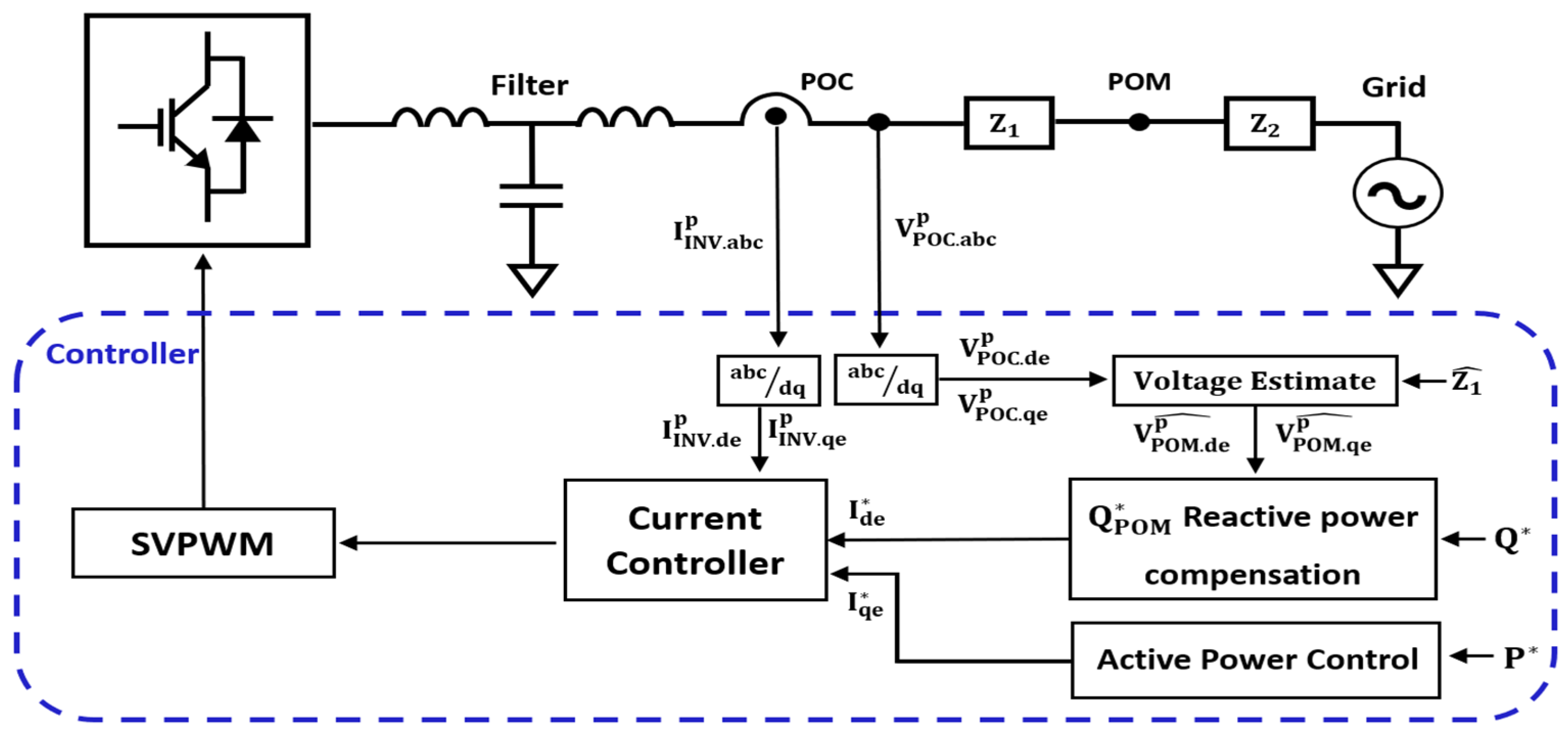
Furthermore, the proposed method enables each IBR to perform reactive power compensation at the POM by utilizing the estimated impedance. Similarly to previous approaches that leveraged reactive power injection to compensate voltage variations at the POC, the IBR predicts reactive power errors at the POM based on the estimated line impedance and adjusts its reactive current output accordingly, while maintaining active current fixed by Maximum Power Point Tracking (MPPT) [
14,
15].
The paper is organized as follows.
Section 2 presents the modeling of the IBR system for grid impedance estimation, constructs the equivalent circuit, and explains the negative-sequence current injection method along with the phase synchronization assumption.
Section 3 analyzes the definition and impact of voltage unbalance and proposes a compensation method based on negative-sequence current injection.
Section 4 analyzes the impact of voltage drop at the POM on reactive power error and proposes a method for its compensation.
Section 5 validates the proposed method through both simulation and lab-scale experiments.
2. IBR Plant Modeling for Line Impedance Estimation
The operating characteristics of an IBR are connected to the grid-side impedance, which affects current control and protection settings, and may cause issues such as harmonic resonance and instability. Therefore, accurately estimating the impedance can enhance the control performance and stability of the IBR [
16]. In this chapter, we model an IBR plant integrated into a single inverter along with the grid system and propose a negative-sequence current injection method that enables separate estimation of the impedances before and after the POM. However, it should be noted that the proposed impedance estimation method assumes relatively stable grid conditions. In scenarios where the grid experiences rapid or severe fluctuations, the accuracy and reliability of the estimation may be compromised, limiting the applicability of the method in such dynamic environments.
2.1. System Modeling and Equivalent Circuit Configuration
In large-scale renewable energy grid-connected environments, multiple IBRs are aggregated at the Point of Measurement (POM) and connected to the grid through the Point of Interconnection (POI) [
17]. In this configuration, each inverter has a different transmission path to the POM within the power plant, resulting in distinct line impedances between each IBR and the POM.
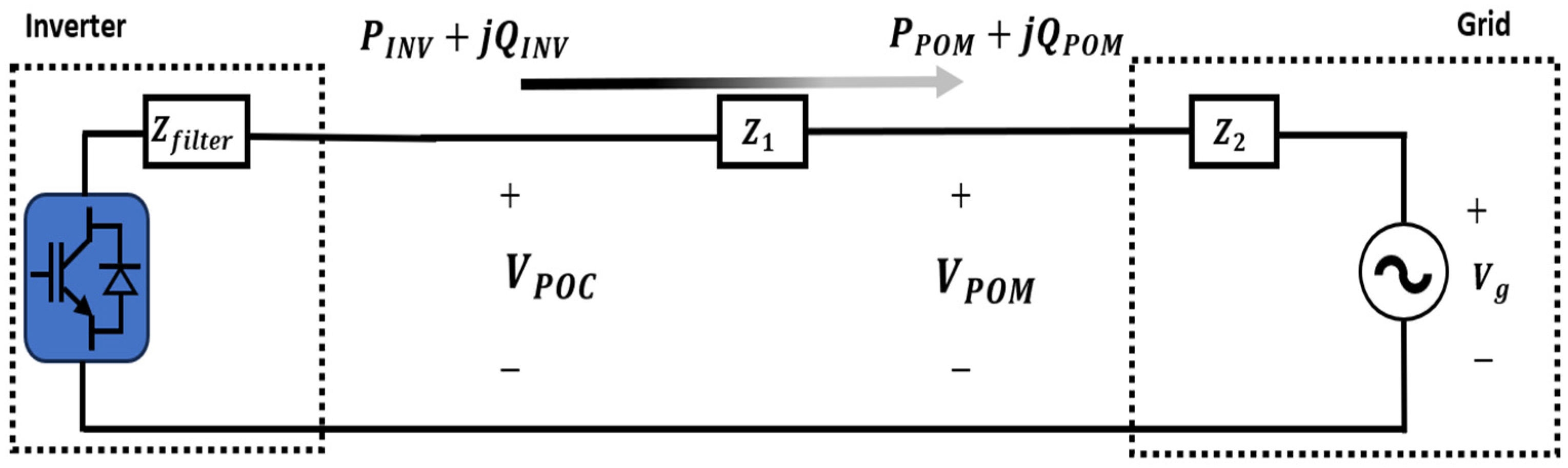
In this paper, the system is configured as a plant model integrated into a single inverter. Using a single-inverter-based model facilitates the interpretation of algorithm results, improves simulation speed and simplifies the output waveform. This enables the operating principle of the algorithm to be clearly verified. Furthermore, the proposed algorithm estimates the impedance between the IBR and the Point of Measurement (POM) independently by injecting a negative-sequence current before the plant begins generation. The overall system configuration is shown in
Figure 1.
The inverter is modeled as a 2-level inverter connected to the grid through an LCL filter. This configuration reflects a typical setup for grid-connected IBR and provides realistic dynamics for impedance estimation and control. The equivalent circuit model distinguishes three components: the filter impedance
following the inverter output, the line impedance
from the POC to the POM, and the actual grid impedance
beyond the POM. Accordingly, the total impedance is composed of two segmented components rather than a single element. Based on this structure, the voltage vector equation can be expressed as follows.
2.2. Impedance Estimation Using Negative-Sequence Current Injection
In the steady state, the inverter output is composed of positive-sequence current, and the voltage difference between the POC and POM is determined by
. In this paper, the conventional negative-sequence current injection method is extended to enable the separate estimation of both
and
[
18]. First, the relationship between the negative-sequence component and impedance used in the conventional negative-sequence injection-based impedance estimation method is given by Equation (3). In this case, the reference frame used in the equation is the synchronous rotating reference frame, with the phase angle at the POC as the reference. Based on the assumption that the positive- and negative-sequence impedances are identical, impedance can be estimated using the negative-sequence component [
19]. The relationship is expressed as follows.
Note that Equation (3) estimates the total impedance
using only voltage and current measurements at the POC across two operating points, utilizing delta values (Δ) to eliminate the influence of the unknown and fluctuating grid voltage
. This makes the method robust and only requires POC-side measurements. This method involves varying the negative-sequence current
at two different operating points and observing the response of the negative-sequence voltage
to estimate the impedance. In this context, the delta (Δ) values represent the variation in voltage and current components measured at two different operating points. Based on this method, this paper proposes a method for estimating
using the voltage information at the POM point, as follows.
In contrast, Equation (4) directly estimates the impedance of the line segment between the POC and POM by utilizing synchronized voltage measurements at both points and the inverter output current at POC. This requires additional voltage measurement at POM but provides segment-specific impedance estimation. Through Equation (4), the real and imaginary components of can be estimated using only the inverter output current , the voltage at the POC , and the voltage at the POM . After that, the total line impedance + can be calculated using Equation (3), and by subtracting the previously computed , can be estimated. Since has a low variation potential due to grid characteristics, it is treated as a fixed value after the initial estimation and used accordingly, while only is considered a time-varying parameter for continuous estimation. Since can vary depending on the operating conditions of the grid or parallel-connected equipment, continuous tracking is required. In this structure, there is no need to use separate POM voltage information for the estimation of . Impedance estimation can be performed using the already-obtained information.
2.3. Phase Synchronization Assumption for POM Voltage Information
The impedance estimation method proposed in this paper assumes the real-time acquisition of three-phase voltage information at the POM point, which is then transformed into the DQ frame for analysis in the synchronous reference frame [
20]. Real-time phase synchronization between POC and POM is challenging due to inevitable communication delays and network infrastructure limitations. These delays can introduce phase angle errors that degrade the accuracy of impedance estimation. Moreover, synchronization loss or fluctuations may lead to instability in the control system and unreliable estimation results, particularly in fast-changing grid conditions. However, to address this challenge, two approaches can be considered.
The first approach is the real-time phase synchronization method between the POC and POM. However, in large-scale renewable energy grid-connected environments, the physical distance between these two points is often significant, which makes real-time synchronization impractical due to communication delays and infrastructure limitations. Therefore, it is more practical to assume that the phase angles at the POC and POM are identical.
The second approach uses indirect synchronization by assuming that the phase angles at both points are equal. To achieve this, the positive-sequence current is controlled to zero, ensuring no phase angle difference, while the dual-controller setup independently manages the negative-sequence current. The dual controller allows the positive-sequence and negative-sequence to operate independently without influencing each other, enabling the inverter to maintain positive-sequence synchronization while simultaneously performing grid impedance estimation using the negative-sequence component. This approach does not require communication-based control for phase synchronization, yet it enables accurate impedance estimation based on the POM voltage information.
In this architecture, the positive-sequence current is regulated to zero, thereby ensuring that the phase reference at the POC and POM points remain identical. As a result, the magnitude of the negative-sequence components in the synchronous reference frame remains constant, regardless of any time delay. This means, as shown in
Figure 2, even if the DQ-transformed voltage at the POM arrives with a communication delay, the phase reference remains aligned due to the assumed identical phase angles, thereby preventing calculation errors caused by phase angle differences.
Figure 2a illustrates the phase angle deviation between the POC and POM points that occurs when positive-sequence currents are injected. In contrast,
Figure 2b shows that injecting negative-sequence currents and separately measuring the reference frames at the POC and POM points allows the phase alignment between the two locations to be maintained.
The key point here is that the impedance estimation method proposed in this paper is performed during the initial operation, before the IBR delivers active power to the grid, that is, when the positive-sequence active power is zero. As explained in
Section 2.2, estimating
requires POM information. When power generation is in progress, it is practically impractical to maintain the positive-sequence active power at zero. Therefore,
is estimated before generation starts, and
is treated as a variable for continuous estimation. This separation allows the total impedance
to be dynamically tracked by continuously estimating
, enabling adaptive IBR control in response to grid events such as switching operations, faults or load changes. Consequently, the proposed method helps mitigate resonance-related instability, which is a key concern addressed in the introduction.
In large-scale grid-connected renewable energy systems, the significant physical distance between POC and POM, along with complex and potentially unreliable communication networks, exacerbate synchronization challenges. Frequent network delays or interruptions can cause phase misalignments, reducing estimation accuracy and system stability. Furthermore, as the number of inverters and measurement points increases, maintaining synchronization becomes more difficult, posing scalability issues. While the dual-controller approach mitigates some challenges by separating positive- and negative-sequence controls, it introduces additional computational complexity and real-time control demands that may limit practical implementation in large-scale systems.
3. Interaction Between Voltage Unbalance and Negative-Sequence Current Injection
The grid impedance estimation method based on negative-sequence current injection discussed in the previous section demonstrates simple implementation and high effectiveness. However, if negative-sequence current is injected without considering grid conditions, it can lead to increased voltage unbalance. This chapter explains the impact of voltage unbalance on power system and inverter operation, as well as the control strategy to compensate for it.
3.1. Definition and Impact of Voltage Unbalance
Voltage unbalance refers to an imbalance in the voltage magnitude or phase angle between the three phases and is defined as follows [
21].
Such voltage unbalance can lead to various negative effects, including increased eddy current losses in rotating machines, reduced line capacity, and higher copper losses in single-phase feeders. In particular, for inverter-based equipment, it may cause frequent maloperation of protection relays and phase angle errors in control systems, ultimately degrading control stability [
22]. Due to these adverse effects, international regulations on voltage unbalance exist, such as the European standard EN50160, which recommends maintaining voltage unbalance within 2% to 3% [
23,
24,
25]. To comply with such regulations, inverters must actively compensate for voltage unbalance through dedicated control algorithms.
3.2. Voltage Unbalance Compensation Through Negative-Sequence Current Injection
The inverter can compensate for voltage unbalance by properly regulating the negative-sequence current through appropriate control, which can be mathematically expressed as follows [
26].
As shown in Equations (6)–(9), voltage unbalance can be restored to a balanced state by adjusting the direction and magnitude of the negative-sequence current vector so that the negative-sequence voltage generated by the inverter output current cancels out the existing negative-sequence voltage. The phasor diagram in
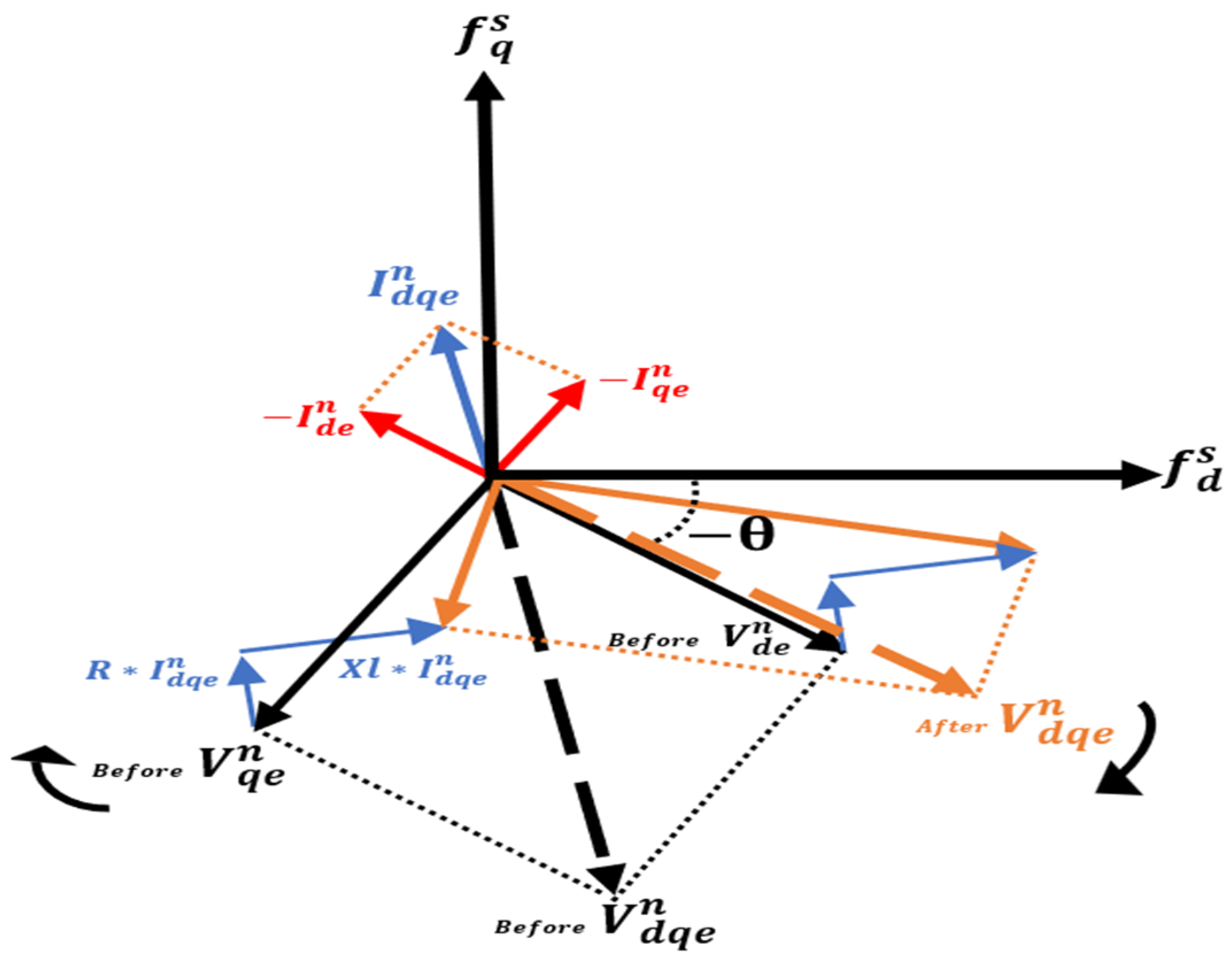
Figure 3 visually illustrates the effect of this voltage unbalance compensation.
Figure 3 shows the negative-sequence voltage vector before (black dashed line) and after (orange dashed line) the injection of negative-sequence current. The clockwise-rotating negative-sequence voltage component can be represented in the dq-axis synchronous reference frame as
and
(black solid lines), which facilitates clear visualization of the phase relationship. The injected dq-axis current vector
,
(red solid line) is designed to have a 180° phase difference relative to the negative-sequence voltage, effectively counteracting its effect. Due to the grid impedance, this current injection reduces the magnitude of the negative-sequence voltage vector, as shown by the transition from the black to the orange dashed line. This reduction mitigates voltage unbalance, which is crucial for maintaining stable grid operation and power quality [
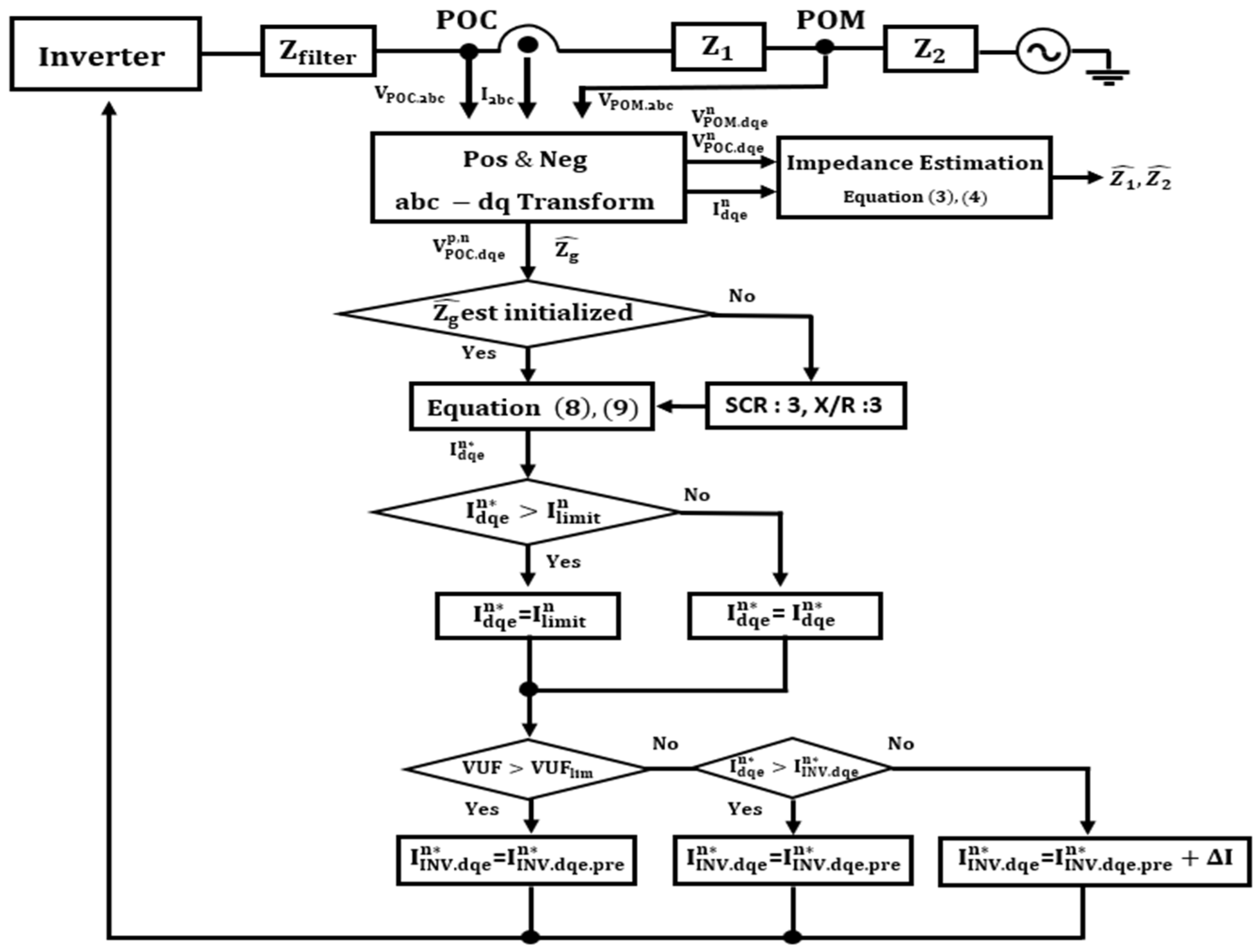
27]. The specific procedure for generating this current reference is detailed in the flowchart of
Figure 4.
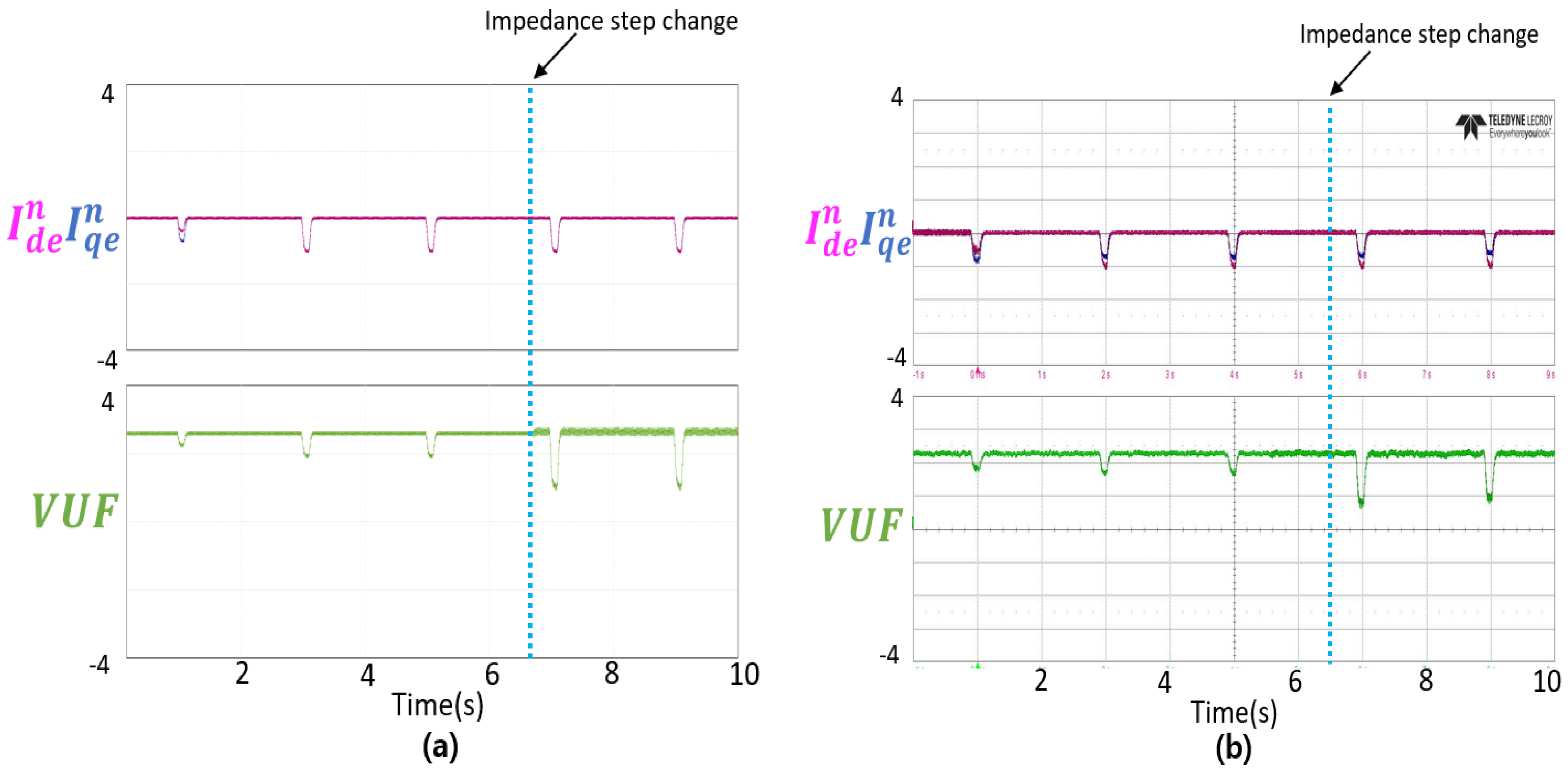
First, under initial conditions where the grid impedance has not yet been estimated, the current reference is generated based on a fixed Short Circuit Ratio (SCR) and X/R ratio (e.g., SCR = 3, X/R ratio = 3), considering the possibility that the grid may be weak. After the impedance has been estimated, the magnitude of the negative-sequence current is determined based on the estimated impedance values using Equations (3) and (4), and applied to Equations (8) and (9). To prevent excessive negative-sequence current injection, a limiter is applied before generating the negative-sequence current reference . If the Voltage Unbalance Factor (VUF) is smaller than the user-defined minimum , it is assumed that the voltage unbalance ratio is , and the negative-sequence current reference is generated according to Equations (8) and (9).
During the injection of the current at the generated reference current magnitude , if the VUF increases beyond the system-defined limit value , the inverter negative-sequence current reference will no longer be increased, and the previous reference value will be maintained to prevent further deterioration of voltage unbalance. If not, the is incremented by per sampling period until it reaches . should be appropriately selected to prevent sudden changes in VUF, for example, [per second, 10% of IBR rated current]. In this paper, is set to 30 A per second.
6. Conclusions
This paper proposes a method to estimate the line impedance between the Point of Connection (POC) and the Point of Measurement (POM) for Inverter-Based Resources (IBRs) and improve the reactive power control performance of the IBR plant. The proposed impedance estimation method, based on negative-sequence current injection, allows each inverter to individually estimate the line impedance between the POM points while simultaneously mitigating voltage unbalance. Additionally, a method to compensate for reactive power distortion at the POM point based on the estimated impedance is presented.
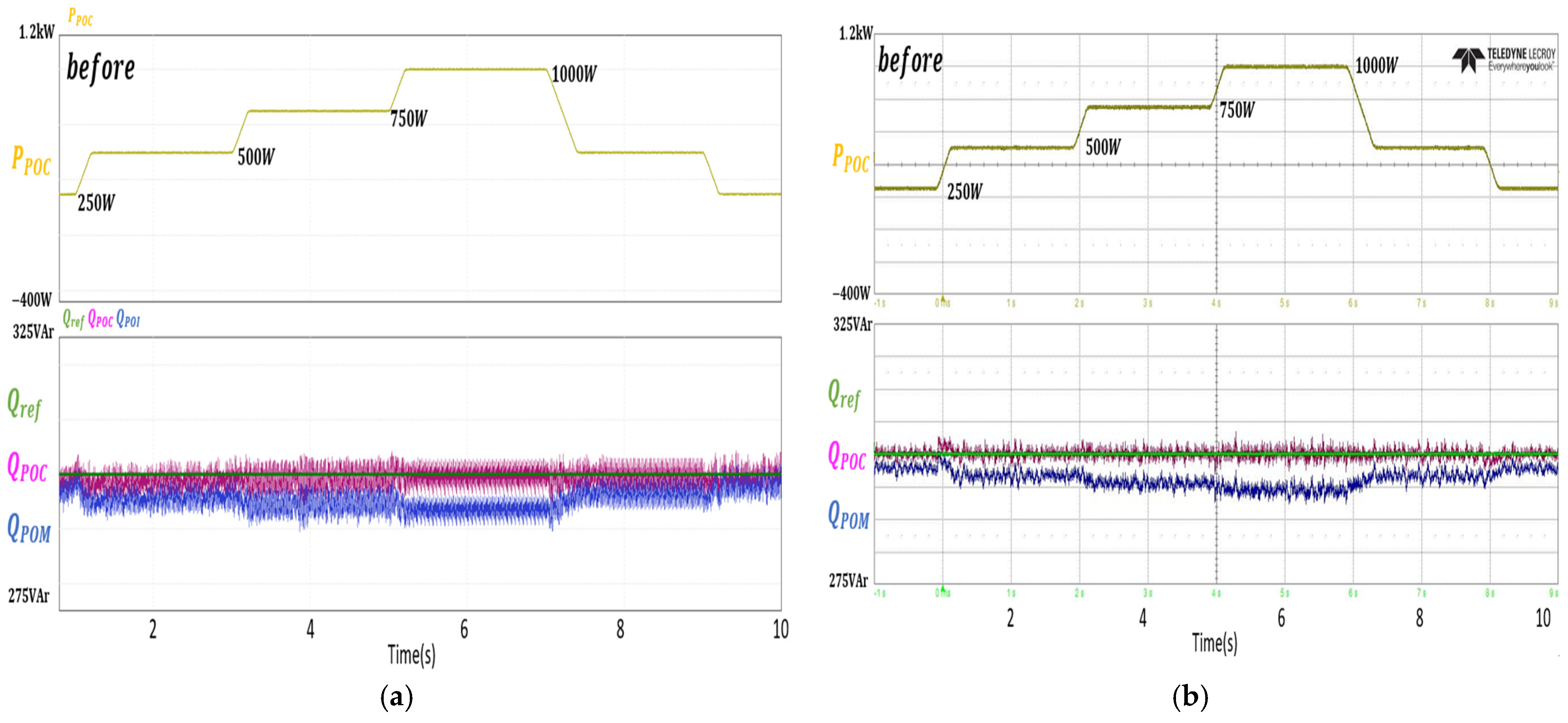
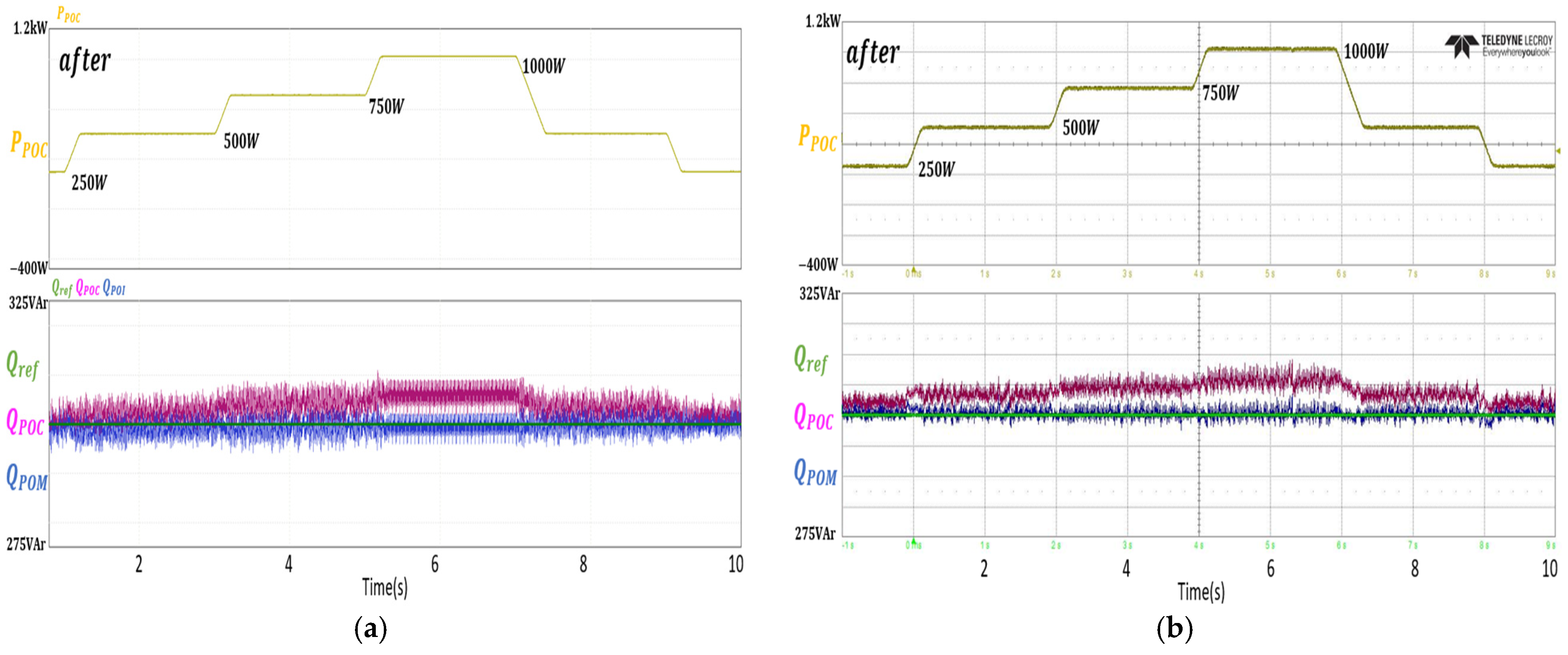
To validate the effectiveness of the proposed impedance estimation and reactive power compensation at the POM point, experiments were conducted in an environment consisting of a 3 kW inverter, line impedance, and an unbalanced three-phase grid. The experimental results were cross validated with simulations. The cross-validation results showed that even with a step change in line impedance, the resistance and inductance were estimated with an error of less than 2%. Additionally, the voltage unbalance factor was reduced to a limited extent. Before reactive power compensation at the POM point, the error between the reactive power reference and the actual reactive power was 2% for 1 kW and 300 Var, but after compensation, the reference and error were significantly reduced to a minimal level, confirming the effectiveness of the proposed compensation method.
The method proposed in this paper has the advantage of enabling impedance estimation and reactive power compensation by modifying only the inverter current control. Therefore, if the proposed method is applied to IBRs, it could support the stable maintenance of power quality by the IBR, regardless of the power plant and grid conditions.


