Article

Positive-Mode-Damping Stability Criterion Application and Damping Solutions in Microgrid-Integrated Transmission Grids

by
Oriol Cartiel
1,
Pablo Horrillo-Quintero
2,
Juan-José Mesas
3,*,
Pablo García-Triviño
2,
Raúl Sarrias-Mena
4,
Luis M. Fernández-Ramírez
2 and
Luis Sainz
1
1
Department of Electrical Engineering (DEE), Escola Tècnica Superior d’Enginyeria Industrial de Barcelona (ETSEIB), Universitat Politècnica de Catalunya—BarcelonaTech (UPC), Av. Diagonal 647, 08028 Barcelona, Spain
2
Research Group in Sustainable and Renewable Electrical Technologies—SURET (PAIDI-TEP-023), Department of Electrical Engineering, ETSIA, University of Cádiz, Avda. Ramón Puyol, s/n, 11202 Algeciras, Spain
3
Department of Electrical Engineering (DEE), Escola d’Enginyeria de Barcelona Est (EEBE), Universitat Politècnica de Catalunya—BarcelonaTech (UPC), Av. d’Eduard Maristany 16, 08019 Barcelona, Spain
4
Research Group in Sustainable and Renewable Electrical Technologies—SURET (PAIDI-TEP-023), Department of Engineering in Automation, Electronics and Computer Architecture & Networks, ETSIA, University of Cádiz, Avda. Ramón Puyol, s/n, 11202 Algeciras, Spain
*
Author to whom correspondence should be addressed.
Energies 2025, 18(12), 3089; https://doi.org/10.3390/en18123089
Submission received: 15 April 2025 / Revised: 3 June 2025 / Accepted: 5 June 2025 / Published: 11 June 2025
(This article belongs to the Special Issue Emerging Trends in Enhancing Power Grid Performance)

Abstract

:
Stability problems are increasing in current power systems with a large number of electronic converters, such as microgrids (MGs) and microgrid clusters (MGCs). Frequency-domain methods, commonly used to analyse traditional power system stability, can also be extended to MGs. In particular, the positive-mode-damping (PMD) stability criterion is a simple and practical method to evaluate the stability of multi-terminal power electronics-based systems, making it a powerful tool for addressing stability issues in MGCs. This paper extends the application of the PMD stability criterion to assess stability in MGC-integrated transmission grids. Moreover, it presents two bandpass filter-based active and passive damping compensators and examines their effectiveness in mitigating instabilities in MGCs. A modified IEEE three-bus power system integrating an MGC is used to conduct a small-signal harmonic stability study and apply active and passive damping solutions with the PMD stability criterion. The modified IEEE three-bus power system is implemented in real-time simulations using a hardware-in-the-loop setup with OPAL-RT4512 to validate the results obtained from MATLAB/Simulink R2022a simulations.

1. Introduction

The proliferation of power electronics in traditional power systems has paved the way for new paradigms in electrical energy distribution, such as microgrids (MGs) and microgrid clusters (MGCs). MGs and MGCs offer the following benefits [1]: (i) local generation and consumption of electricity; (ii) enhanced integration of renewable energy technologies and energy storage systems (ESSs); and (iii) improved efficiency, reliability, and resilience of electrical grids. Nevertheless, they also present several challenges, such as power system instabilities [2,3]. This is due to the widespread use of power electronics and the unique characteristics of these grids, which are typically composed of clusters [4,5,6,7]. The main concepts and relevant issues related to stability in MGs are discussed in [4,7], while detailed modelling of MG components for stability analysis is explored in [5,6,7]. The dynamics and quality challenges of MGs and MGCs differ significantly from those of traditional power grids [4,8,9,10]. These differences, such as smaller size, higher presence of distributed generators (DGs), and different ratios (R/X) in feeders, require a reevaluation of stability concepts, studies, and solutions in MGs and MGCs. There is a need to assess stability and explore new scheduling, configurations, and smart control schemes to ensure reliability [11,12]. Instability in MGs emanates from two major causes [4,7,8]: load power flow and system controls. Load power flow refers to the grid’s capacity to keep a balanced power supply and effectively distribute demand among DGs. Limitations in this capacity can result in stability issues, including voltage and frequency oscillations in both traditional grids [7,13] and MGs [3]. Although power supply and balance instabilities, such as voltage oscillations caused by load power flow, are less common in MGs due to their smaller size, the limitations of DGs and load sensitivity are significant risk factors. Unlike in power grids, in MGs these instabilities are characterised by a strong coupling between voltage and frequency oscillations. System control refers to converter-driven instabilities [13]—also known as converter control system instabilities in MG stability studies [3]. These instabilities are primarily caused by the interaction of power electronics with the grid. While the proliferation of power electronics has enabled various applications, such as MGs [4,8], overcoming the technological challenges posed by the interactions between traditional electrical components and new electronic components remains essential. For example, voltage source converters (VSCs) and their control [14,15,16] can lead to both fast- and slow-interaction converter-driven instabilities [7,13] (also referred to as large- and small-disturbance converter control system instabilities in [3]) primarily caused by small-signal perturbations. Overall, understanding and addressing these instability phenomena in MGs and MGCs are crucial, as highlighted in [3]. Moreover, although frequency variations can be significant in MGs [2], they are not considered in this study. A constant frequency is assumed, as the focus is on fast dynamic instability caused by interactions between power electronics controls and system components (i.e., harmonic stability issues) [13]. These instabilities result in high-frequency oscillations, allowing slow interactions related to frequency variations to be excluded from the analysis. All of these stability issues in MGs are presented and illustrated with different examples in [3].
Various approaches can be used to assess stability in modern power systems, including MGs and MGCs (see Table 4 of [7]). These methods are primarily categorised into time-domain eigenvalue analysis [2,17] and frequency-domain techniques [18,19]. Time-domain eigenvalue analysis is a widely adopted state-space approach due to its ability to provide a comprehensive understanding of system dynamics [4,8,9]. Moreover, participation factors (PFs) enable the characterisation of how state variables contribute to system modes, thus helping to identify how specific grid components and power electronics controls affect stability [2,7,20,21]. This facilitates both the quantification of system instability and the design of mitigation strategies. However, applying time-domain analysis to multi-terminal power electronics-based systems, such as MGC-integrated transmission grids, poses several challenges: (i) detailed models of all system components are often unavailable, as manufacturers typically supply black-box models for power electronics, and (ii) high-order dynamic equations are required to represent system behaviour accurately [22]. To overcome these limitations, alternative methods based on the impedance-based characterisation of grids—by separating them into source and load subsystems—have been developed. These include Laplace-domain eigenvalue analysis [11,12], as well as frequency-domain methods such as the Nyquist criterion [7,9,12,23]. These approaches are less computationally intensive and offer the possibility of using black-box models to characterise system stability [24]. However, source–load partitioning is not readily applicable to multi-terminal converter-based systems like MGs. To address this, more generalised methods such as the Generalised Nyquist Criterion (GNC) [18,25] and the positive-mode-damping (PMD) stability criterion applied to nodal analysis [20,26,27,28] have been introduced for multi-terminal power electronics-based systems. Despite its applicability, the GNC suffers from several limitations [22,26,29,30,31,32,33]: (i) its reliance on source–load decomposition may lead to inaccurate conclusions; (ii) unlike time-domain eigenvalue methods, it does not support PF analysis; and (iii) its results are less intuitive to interpret. To overcome these drawbacks, the PMD stability criterion was recently proposed [26]. It provides a practical and intuitive method based on Resonance Mode Analysis (RMA) [34,35,36] for assessing system stability by identifying critical modes in the nodal admittance matrix. Recent advancements, such as faster RMA [36], which uses an iterative method to determine only the dominant eigenvalue of the inverse nodal admittance matrix, have further reduced computational burden. Additionally, the PMD criterion has been enhanced through the integration of black-box models, sensitivity studies based on PFs, and the introduction of a damping margin (DM) indicator—a metric for quantifying the degree of stability in multi-terminal power electronics-based systems [20,37,38,39]. Given these methodological advantages, the PMD criterion stands out as a robust approach for evaluating stability phenomena in such systems [20,26]. However, to the best of the authors’ knowledge, it has not yet been applied to MGs or MGCs.
Hardware-in-the-loop (HIL) simulation equipment, such as Typhoon, OPAL-RT, and dSPACE, has emerged as a powerful tool to incorporate complex real-time simulation applications into various transmission power system studies, including MG analysis [40]. First, a MATLAB/Simulink power system model is developed in the time domain, which is then transformed into a compatible format for execution on a real-time simulator. This platform is selected for its adaptability, scalability, and features, all within an economical framework [41]. This approach enables early validation of stability functionalities. Virtual power plants are a cost-effective alternative and provide the flexibility to test extreme conditions, an achievement that could be prohibitively expensive or impractical using real hardware. As the equations and states of the simulated system are accurately resolved, the real-time simulator adeptly replicates the behaviour of the real-world physical system. Consequently, the use of HIL tools is a novel and increasingly common approach for validating studies as it offers a wide range of benefits. Within the domain of small-signal instability attributed to power electronics, particularly in MGs and MGCs, some instances of the use of OPAL-RT can be found in the literature, such as in [12]. Additionally, other HIL tools are referenced in [42,43]. Since the PMD stability criterion is not applied in stability studies using OPAL-RT as a verification tool, and even less in MGs or MGCs, the need arises to utilise it to leverage its capabilities.
Passive and active damping compensators are often considered to mitigate instabilities caused by low-damped resonances. Passive damping methods involve the use of resistors, capacitors, and LC filters connected to the grid [11,14]. However, this approach is not optimal because it often leads to additional losses, physical constraints, and extra costs in the grid. This is why active damping methods are more commonly employed [12,44,45,46]. These methods use control techniques to introduce virtual damping in the grid, avoiding drawbacks associated with passive approaches. Despite the widespread recognition of active damping methods as effective stability solutions, their design remains an ongoing research challenge in MGC-integrated transmission grids. In [37], the study design of two bandpass filter-based active and passive damping compensators for converter-based grids using the DM indicator is presented.
The paper offers three main contributions:
  • Application of the PMD stability criterion to MGC-integrated transmission grids: This study applies the PMD stability criterion, based on faster RMA, to assess small-signal harmonic stability in MGC-integrated transmission grids (referred to as small-disturbance converter control system stability in [3]), addressing limitations in existing time-domain and impedance-based methods. Notably, this approach has not previously been applied to such grids using this stability criterion, thereby extending its generality.
  • Extension of damping compensator design using the PMD stability criterion: This study extends the design and evaluation of two bandpass filter-based damping compensators—one active and one passive—by using the PMD stability criterion as a design tool to mitigate instabilities in MGC-integrated grids. This is a practical methodology for selecting the compensation location and parameters.
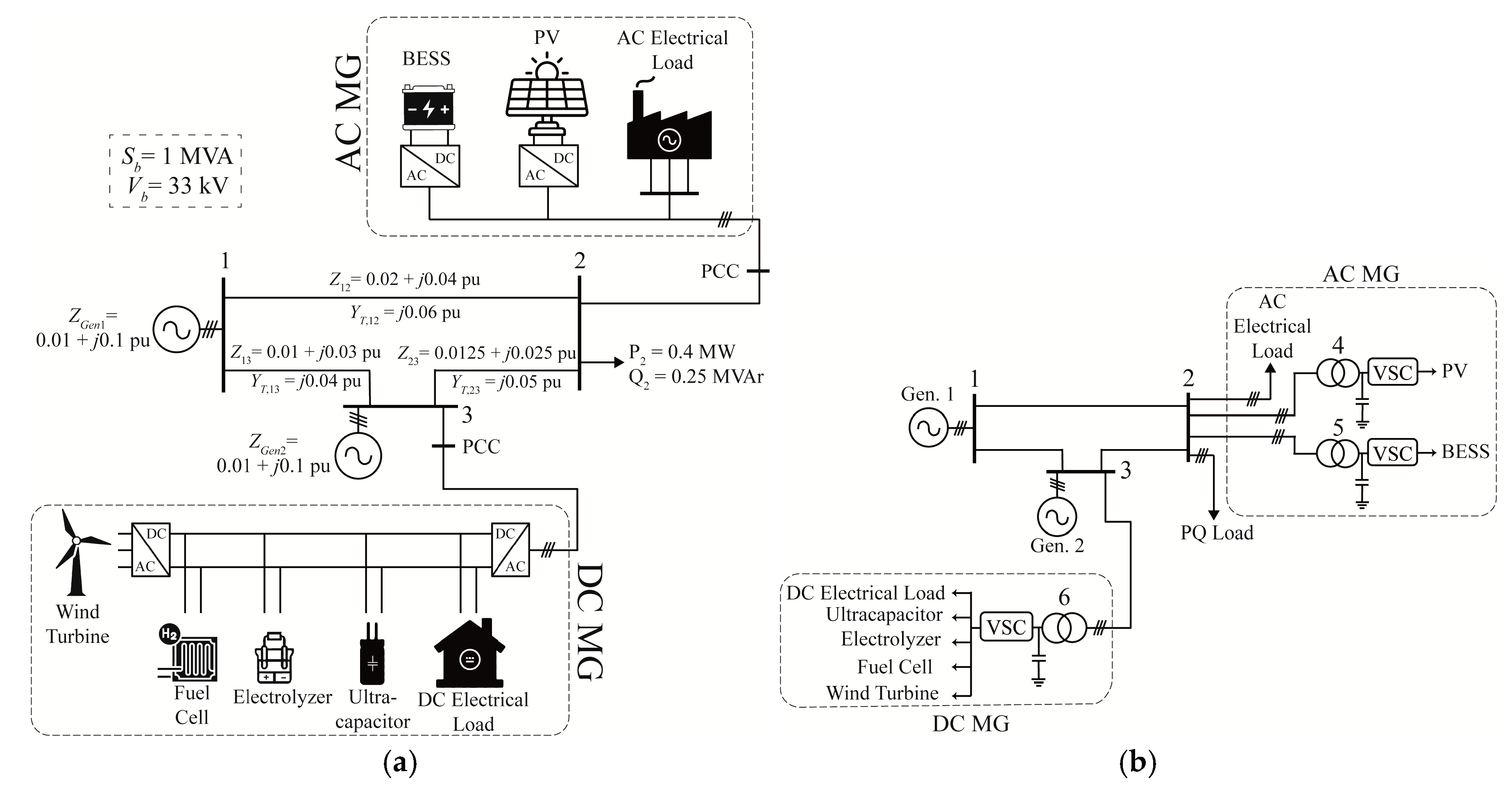
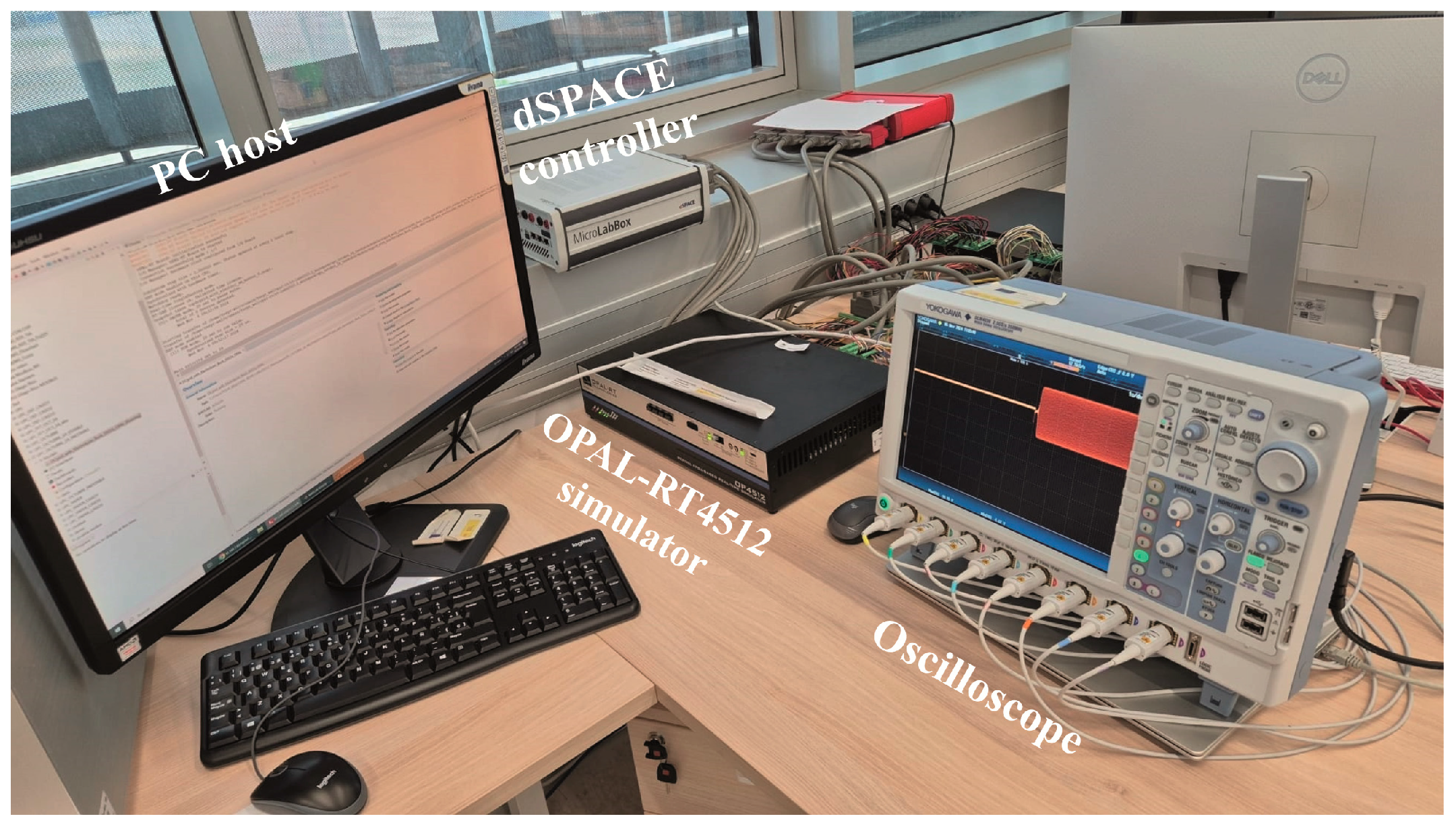
  • Validation under realistic operating conditions: This study validates the proposed PMD stability criterion and damping compensators on a modified IEEE three-bus power system [47] that integrates an MGC [48,49,50,51]. Validation is performed by MATLAB/Simulink R2022a (The MathWorks, Inc., Natick, MA, USA) simulations and experimental HIL simulations using OPAL-RT (OPAL-RT Technologies, Montreal, Quebec, Canada), ensuring the efficacy of the proposed PMD stability criterion under realistic operating conditions [52]. Specifically, the OPAL-RT4512 HIL simulator is used to execute the MGC-integrated transmission grid in real time, while the MG local control is implemented within a dSPACE MicroLabBox (dSPACE GmbH, Paderborn, Germany) unit, establishing analogue inputs/outputs between the OPAL-RT4512 HIL simulator and the dSPACE MicroLabBox. Signals are measured with a Yokogawa DLM4038 oscilloscope (Yokogawa Electric Corporation, Tokyo, Japan). This real-time validation highlights the practicality and reliability of the proposed approach for early-stage control testing prior to practical implementation in real-world scenarios.

2. Small-Signal Model of Multi-Terminal Grid-Connected Power Electronics-Based Converters

The small-signal impedance-based equivalent circuit of multi-terminal grid-connected power electronics-based converters, such as the multi-terminal grid-connected VSCs in Figure 1a, is shown in Figure 1b. The power electronics-based converters are represented as current sources in parallel with the equivalent VSC admittances, and the grid is characterised by the nodal admittance matrix YG(s). The next subsection briefly presents the small-signal model of grid-connected VSCs.

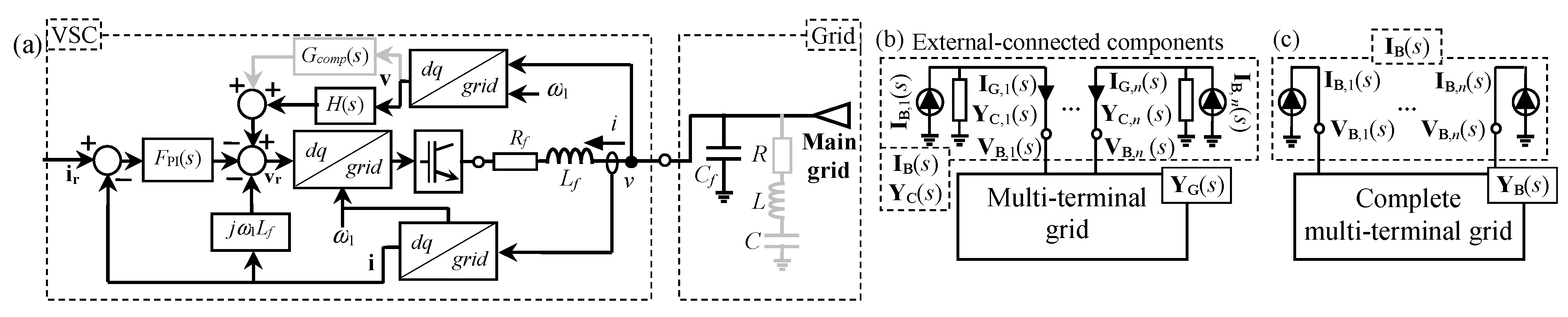
Small-Signal Model of Grid-Connected VSCs

Figure 1a illustrates the equivalent circuit of the grid-connected VSCs through both its block diagram and circuit schematics. The VSC control is characterised only by the inner current control loop, as this study only addresses harmonic instabilities. Consequently, the PLL and outer loops are disregarded as they have low bandwidths [14,25]. The inner current control loop uses a proportional–integral (PI) controller in the dq reference frame, where the complex space voltages and currents, denoted in bold as v and i, are transformed from the three-phase grid components v and i into the dq frame. Additionally, a grid voltage feedforward low-pass filter, represented by the block H(s), is incorporated into the control. The VSC circuit schematic includes the coupling reactor Lf (along with its associated resistance Rf) and the equivalent capacitor Cf of the high-frequency filter.
Based on the above description, the widely known dq-frame VSC current control model is derived by equating Ohm’s law at the converter inductor with the VSC current control law:
v R f + L f s + j L f ω 1 i = e s T d D s k p + k i s F P I s i i r j L f ω 1 i + α f s + α f v ,
where ω1 = 2π·f1 (f1 = 50 Hz) is the fundamental angular frequency and
  • v = vd + jvq and i = id + jiq are the grid voltage and current in the dq frame;
  • vr = vrd + jvrq and ir = ird + jirq are the converter voltage and current references in the dq frame;
  • FPI(s) is the transfer function of the PI current controller with proportional and integral gains of the PI controller kp = Lf·αcc and ki = Rf·αcc and bandwidth αcc;
  • H(s) is the transfer function of the grid voltage feedforward low-pass filter with bandwidth αf;
  • D(s) is the transfer function of the VSC time delay with the time delay Td = qd/fsw, where the factor qd depends on the double- and single-update PWM techniques (i.e., qd ϵ [0.25 … 0.75] and qd ϵ [0.5 … 1], respectively) [14,16], and the switching frequency fsw.
The following relation between the grid voltage and current is obtained from (1) [16]:
i = D s F P I s R f + L f s + j L f ω 1 + D s F P I s j L f ω 1 G v s c s i r + 1 D s H s R f + L f s + j L f ω 1 + D s F P I s j L f ω 1 Y v s c s v ,
where Gvsc(s) is the closed-loop transfer function, and Yvsc(s) is the equivalent admittance of the VSC. It is worth noting that a symmetrical VSC model is obtained when only the current control is considered, and it can be characterised by the complex admittances Yvsc(s) in (2) [16].
Considering (2), the impedance-based equivalent circuit of the grid-connected VSC system is shown in Figure 1b. The VSC (or any other external power electronics-based converter) is represented as a current source IG,i(s), in parallel with the equivalent VSC admittance YC,i(s), along with the grid. This characterises the entire system without any partition and accounts for the rotation issue of VSC reference frames [29]. Alternatively, Figure 1c illustrates the complete equivalent circuit of a multi-terminal grid, where VSCs are considered integral parts of the grid rather than external components. It should be noted that the shunt C filter Yf(s) = Cf·s of the VSC is included in the admittance matrix of the grid. The potential connection of active and passive damping compensators to eliminate system instabilities (as discussed in Section 4) is represented in Figure 1a by the grey components: the G–feedforward gain of the current control and the RLC–shunt filter connected to the grid, respectively.

3. Stability Assessment of Multi-Terminal Grid-Connected Power Electronics-Based Converters

Stability in multi-terminal grid-connected power electronics-based converters in Figure 1b can be assessed using both time-domain and frequency-domain approaches.

3.1. Time-Domain State-Space Approach

Stability of the grid in Figure 1b can be assessed using the time-domain state-space approach:
x t = A x t + B u t y t = C x t + D u t     u t = Δ i t     y t = Δ v t ,
where Δ denotes the small-signal variables, x is the state vector, u is the input vector, y is the output vector, and A, B, C, and D are the model matrices. Stability is addressed from the eigenvalues λi = σi ± i of the state-space matrix system |Aλ·I| = 0, where ωi and −σi represent the angular frequency and damping of the system’s oscillatory mode i, respectively. The system is unstable if any eigenvalue is in the RHP (i.e., if any eigenvalue has σi > 0, introducing negative damping in the system). The frequency of the oscillations is fi = ωi/2π. Additionally, eigenvalue sensitivity measures the sensitivity of eigenvalues to the elements of A [2,20]. Based on this concept, PFs are calculated as the sensitivity of eigenvalues to the diagonal elements of the state matrix [2], i.e., the participation of a specific eigenvalue in a particular state variable. Under certain initial conditions, these factors indicate the degree of participation of state variables in the system’s modes. This facilitates the analysis of how various components of the grid and power electronics controls, associated with these state variables, affect stability [20,21].

3.2. Positive-Mode-Damping Stability Criterion

Frequency-domain impedance-based approaches are becoming increasingly attractive for stability assessment as they use fewer complex systems of equations and provide detailed information with reduced computational effort. As shown in Figure 1b, frequency-domain stability studies of multi-terminal grid-connected power electronics-based converters are currently conducted through the characterisation of the entire grid using the voltage node method [27,28]:
I G s = Y G s V B s I G s = I B s Y C s V B s V B s = Y B s 1 I B s     Y B s = Y C s + Y G s ,
where YG(s) characterises the nxn nodal admittance matrix of the grid and YC(s) is an nxn diagonal matrix with the admittance matrices YC,i(s) of the external components connected to the grid buses (including power electronics-based converters). In YC(s), the external components are included in the diagonal position corresponding to their bus number, and if multiple external elements are connected to the same bus, they are summed in that position. If no external component is connected to a bus, the corresponding diagonal element will have a null value. VB(s) and IB(s) represent the nx1 bus voltage and injected current vectors, respectively, and YB(s) is the nxn nodal admittance matrix of the system (see Figure 1c) [26,27]. System stability in (4) is commonly assessed by the GNC. However, the PMD stability criterion has recently been proposed for the stability assessment of multi-terminal grid-connected power electronics-based converters [26]. This criterion is based on the eigenvalue decomposition of the nodal admittance matrix YB(s) at each frequency f over the frequency range given by RMA [34,35,36],
V m ( f ) = λ Y , 1 f 0 0 λ Y , n f Λ Y f 1 I m ( f )         Λ Y f = L f Y B f R f V m ( f ) = L f V B ( f )       I m ( f ) = L f I B ( f ) ,
where Vm(f) and Im(f) are the modal voltage and current vectors, ΛY(f) is the diagonal eigenvalue matrix of YB(f), and R(f) and L(f) = (R(f))−1 are the right (in columns) and left (in rows) eigenvector matrices, respectively. The peak values of the moduli of the modal impedances Zm,j(f) = 1/λY,j(f) of (ΛY(f))−1 (with j = 1, …, n representing the mode number) are referred to as critical resonance modes (Zm,c(fr)) at resonance frequency fr. They are used to assess grid-connected power electronics-based stability. Faster RMA has recently been proposed as an alternative to traditional RMA to efficiently obtain only the smallest modulus eigenvalue of YB(s) (i.e., the largest modulus eigenvalue of ZB(s)) at each frequency f, i.e., the critical modes Zm,c(f), and therefore the critical resonance modes Zm,c(fr). It should be noted that the result of applying faster RMA is the envelope of all impedance matrix modes obtained by RMA. All of this aims at assessing grid-connected power electronics-based stability with the same accuracy as RMA but in a more efficient manner (see details in [36]).
Regarding multi-terminal power converter-based grids, the PMD stability criterion relates the angular frequency of the system’s oscillatory mode i, ωi, to the resonance frequency fr. It also connects the damping of the system’s oscillatory mode i, −σi, to the ratio between the resistance of the critical resonance modes Rm,c(fr) (the real part of Zm,c(fr)) and the slope mx,c(fr) of the reactance of the critical resonance modes Xm,c(fr) (the imaginary part of Zm,c(fr)) at fr. Accordingly, the criterion states that the grid is stable if and only if
σ i R m , c f r m x , c f r < 0     m x , c f r = X m , c f / f f = f r   f r     ω i 2 π f r .
It can be concluded that multi-terminal grid-connected power electronics-based stability can be assessed by examining the sign of the ratio between Rm,c(fr) and mx,c(fr) in the frequency domain. This sign is the same as that of σI, as obtained from the time-domain state-space approach. It should be noted that stability assessment only requires analysing the sign of both variables, Rm,c(fr) and mx,c(fr). These variables are the result of the RMA study, with the latter (mx,c(fr)) being determined by analysing the values of Xm,c(fr) at frequencies adjacent to fr. These values provide the information needed to establish the sign of the slope at fr. Accordingly, if mx,c(fr) > 0, the grid is stable/unstable when Rm,c(fr) becomes negative/positive, whereas if mx,c(fr) < 0, the grid is stable/unstable when Rm,c(fr) becomes positive/negative. Thus, stability can be analysed based on the damping resistance Rm,c(fr) of multi-terminal grid-connected power electronics-based converters at fr. Furthermore, the PMD stability criterion enables the calculation of the PFs as PFb,c(fr) = Rb,c(fr)·Lb,c(fr) (where Rb,c(fr) and Lb,c(fr) are the right and left eigenvectors associated with the critical resonance modes Zm,c(fr) and b represents the grid buses). These PFs reflect the sensitivity of eigenvalues to the diagonal elements of the nodal admittance matrix (see proof in [20,35]), i.e., the participation of a specific eigenvalue (or mode) at a particular grid bus. Essentially, they quantify the influence (observability and excitability) of each bus on stability with respect to resonance modes represented by the eigenvalues, helping to identify which devices may affect stability [20,35,39]. Notably, the PMD criterion has recently been extended to include the calculation of a DM indicator based on PFs and critical resonance modes [37], providing a simple conductance-/resistance-based measure of system stability. To determine the system’s DM, the margin associated with the impedance’s critical modes must be calculated at each resonance frequency (local DM). The DM indicator, derived from the PMD stability criterion results, is computed as [37]
D C M h f r R e 1 / P F h c f r Z m , c f r ,
where DCMh(fr) denotes the damping conductance margin at fr, and PFh,c(fr) is the PF of the most affected bus b by the critical mode Zm,c(fr). All local DMs are required to evaluate the overall system stability using a global damping margin, DCM, as detailed in [37].

3.3. Advantages of the Positive-Mode-Damping Stability Criterion Compared to Existing Methods

Stability assessment techniques can generally be categorised into time-domain eigenvalue analysis [2,17] and frequency-domain techniques [18,19].
Time-domain eigenvalue analysis provides detailed insights into the system’s dynamic behaviour, making it valuable for identifying subsystems contributing to stability issues. However, it requires extensive knowledge of the system, including linearised models and parameter data, and is computationally intensive. This limits its practicality for real-time applications. Moreover, it cannot accommodate black-box models, which are common in industrial applications [2,19,20,22,25,27].
Frequency-domain techniques overcome some limitations of time-domain eigenvalue analysis by characterising the grid using impedance-based models. These are typically divided into two categories: (i) methods that separate the grid into source and load subsystems and apply Laplace-domain eigenvalue [11,12] or Nyquist-based [7,9,12,23] analyses; (ii) approaches that characterise the full system using the nodal admittance matrix and apply the GNC [18,25]. The former are not well suited for systems with multiple interconnected converters, such as MGs or MGCs, as source–load partitioning may lead to inaccurate conclusions. The latter captures the full-grid dynamics but suffers from key limitations [22,26,29,30,31]: (i) it may yield incorrect conclusions due to misleading associations in the formulation of the closed-loop transfer function [8,31]; (ii) it is difficult to interpret, given the number of Nyquist plots linked to each system eigenvalue [13]; and (iii) it becomes computationally demanding for large-scale systems, requiring the identification of unstable right half-plane poles in large nodal admittance matrices [32,33].
In contrast, the PMD stability criterion has several advantages over both time-domain and GNC-based methods [20,26]:
  • It identifies the frequency of the closed-loop oscillatory modes.
  • It can operate with limited system knowledge (e.g., black-box models).
  • It is insensitive to element associations, avoiding structural ambiguity.
  • It is computationally efficient and simple to apply.
  • It provides intuitive, visually interpretable results.
In summary, while time-domain eigenvalue analysis provides a more detailed understanding of the internal causes of instability, it is resource-intensive and less adaptable to practical scenarios. The PMD criterion offers a more scalable and user-friendly solution that remains valid when full system models are unavailable. Additionally, it avoids the practical drawbacks of GNC-based techniques, making it particularly suitable for modern converter-based grids such as MGs and MGCs.

4. Active and Passive Filter Study

Considering that the sensitivity of the YB(s) eigenvalues λY,j(f) with respect to shunt grid components is the same as that of PFs [39], the damping resistance Rm,c(fr) of multi-terminal grid-connected power electronics-based converters at resonance frequency fr can be effectively modified. This is achieved by connecting passive and active damping compensators (mainly resistive at fr) at the bus with the largest PF (i.e., at the most influential bus in the critical resonance mode at fr). Accordingly, the diagonal term of YB(s) at this bus is modified as
Y b b , m o d f = Y b b f + Y c o m p f ,
where Ybb(f) is the diagonal term of YB(s) at bus b, Ybb, mod(f) is the modified diagonal term of YB(s) at bus b, and Ycomp(f) is the admittance of the passive and active damping compensators. These compensators can be implemented using the VSC control (active damping compensators) or RLC–shunt filters connected to the grid (passive damping compensators), as shown in Figure 1a.

4.1. Active Damping Compensator

The active shunt compensator is obtained from the feedforward filter included in the current control loop (grey box in Figure 1a), which modifies the equivalent admittance of the VSC (2) as
Y v s c c o m p = Y v s c s + D s R f + L f s + j L f ω 1 + D s F P I s j L f ω 1 G c o m p s Y c o m p s ,
where Gcomp(s) is the transfer function of the feedforward filter,
G c o m p s = 0.1 G c p f r ω r s s 2 + 0.1 ω r s + ω r 2       ω r = 2 π f r ,
with fr representing the centre frequency (equal to the resonance frequency) and Gcp(fr) representing the gain at fr. It should be noted that the gain of the feedforward filter has a resistive behaviour of value Gcp(fr) at fr, which allows the compensation of the damping resistance of multi-terminal grid-connected power electronics-based converters and the mitigation of system instability, i.e.,
G c o m p j ω r = 0.1 G c p f r j ω r 2 ω r 2 + 0.1 j ω r 2 + ω r 2 = G c p f r .

4.2. Passive Damping Compensator

The passive damping compensator is obtained from an RLC–shunt filter connected to the grid in Figure 1a:
Y c o m p s = 1 R c p + L c p s + 1 C c p s       L c p 2 π f r = 1 C c p 2 π f r .
It should be noted that the gain of the RLC–shunt filters has a resistive behaviour of value Rcp at fr, which allows the compensation of the damping resistance of multi-terminal grid-connected power electronics-based converters and the mitigation of system instability, i.e.,
Y c o m p j ω r = 1 R c p + L c p j ω r j C c p ω r = 1 R c p .

4.3. Design of Damping Compensators Based on the Positive-Mode-Damping Stability Criterion

Given an oscillatory system at the resonance frequency fr, the steps to design the bandpass filter-based active or passive damping compensators using the proposed DM indicator with the PMD stability criterion are summarised as follows (see [37] for details):
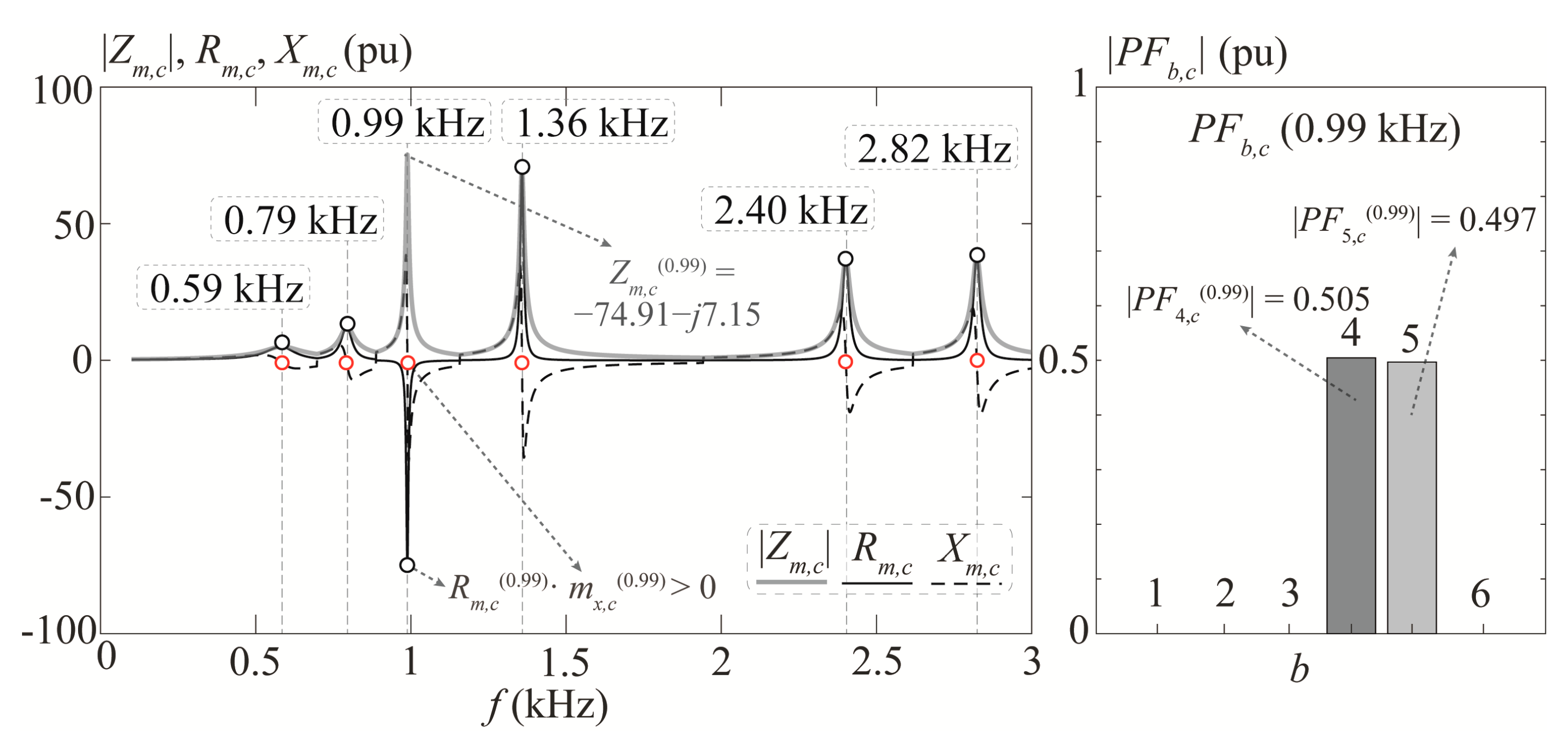
  • Calculate all PFs of the critical resonance mode Zm,c(fr) at fr, and select the highest one, PFh,c(fr), which identifies the bus b = h with the largest contribution to the resonance.
  • Compute the local DCMh(fr) using (7).
  • Determine the required compensator admittance Gcp(fr) to mitigate the resonance:
i :   R e Y h h f r + Y c p f r = D C M h f r + G c p f r 0   G c p f r D C M h f r i i :   R e Y h h f r + Y c p f r = D C M h f r + G c p f r 0   G c p f r D C M h f r .
4.
Design the active compensator using (10). In this case, it is advisable to oversize Gcp(fr) by a safety factor of 3–5 to ensure robust damping and adequately compensate for the first term of (9). Alternatively, design the passive compensator using (12) to be connected to bus h, where
R c p = 1 G c p f r       f r = 1 2 π L c p C c p .

4.4. Practical Application of Damping Compensators

Active and passive damping compensators are essential for effectively addressing harmonic stability issues. While both types are designed to achieve similar objectives and share comparable methodologies, they have distinct advantages and disadvantages that significantly affect their applicability in different scenarios. Table 1 provides a comprehensive overview of the benefits and drawbacks of each type, facilitating the determination of the most suitable compensator for specific applications. In summary, active compensators are characterised by their flexibility, efficiency, and precise performance, enabling seamless integration with modern control techniques. However, they may suffer from limitations, including poor dynamic response, increased complexity, and the potential to interfere with the overall performance of VSCs. Conversely, passive compensators are generally simpler and more reliable solutions for addressing harmonic stability problems, offering effective damping across specific frequency ranges. On the other hand, passive compensators can be bulky, expensive, and associated with losses, making them less suitable for high-power applications. Furthermore, they are sensitive to parameter uncertainties and have fixed characteristics once installed, which limits their adaptability in dynamic environments. Overall, while active compensators excel in high-power applications due to their flexibility and precision, passive compensators face challenges related to scalability and effectiveness in such contexts. This understanding is crucial for selecting the appropriate damping compensator based on the specific requirements of each application.

5. Application

The studied MGC-integrated transmission grid, consisting of the modified 33 kV 1 MVA IEEE three-bus test power system and two MGs (one DC type and one AC type), is depicted in Figure 2a (the detailed characteristic parameters of the system are also shown in this figure). This experimental design aims to analyse a typical configuration of MGCs that includes both DC and AC MGs, thus incorporating common renewable energy loads. The DC MG selected in this study consists of a 2.20 MW wind turbine (WT) [48] and various ESSs connected to a 1100 V DC bus. The ESSs comprise a hydrogen setup consisting of a 1 MW fuel cell (FC) [49] and a 1 MW electrolyser (EZ) [50], as well as a 0.5 MW ultracapacitor (UC). Additionally, several DC loads are connected to this MG. The AC MG is composed of a 1 MW battery energy storage system (BESS) [48], a 1 MW PV power plant [51], and AC loads. A VSC is used to transform DC into AC in the PV and BESS connections. Boundary conditions are incorporated based on typical operational ranges and variations observed in MG configurations, as these are essential for ensuring the robustness of the MGC model under different scenarios. The energy balance in the modified IEEE three-bus test power system studied in this work is summarised in Table 2. In the DC MG, the WT delivers 2.20 MW, and the EZ consumes 0.34 MW. The remaining 1.86 MW is delivered to the PCC of the DC MG. Regarding the AC MG, the PV power plant injects 0.98 MW, while the BESS is discharged at rated power, i.e., 1 MW. The AC load consumes 0.3 MVAr. Therefore, the energy balance results in 1.98 MW delivered to the PCC of the AC MG and 0.3 MVAr consumed from the local grid. This energy balance is one of the operational scenarios simulated in the MG system and corresponds to an extreme, potentially unstable operational scenario within the tested MG systems. It should be noted that the high-power levels of each MG lead to a small SCR at the DC and AC PCC, making the modified IEEE three-bus test power system more susceptible to potential instabilities. The above energy balances were obtained from a previous study of the MGC (out of the scope of this paper). The MGC-integrated transmission grid was modelled in, integrated into, and simulated in MATLAB/Simulink using complete models of VSCs and MGs. For accurate time-domain simulation, the PLL and outer loops of VSCs were used. It was then verified using an experimental setup comprising an OPAL-RT4512 HIL simulator to execute the MGC in real time and a dSPACE MicroLabBox unit to integrate the local control. The OPAL-RT4512 unit serves as an HIL simulator, facilitating real-time implementation and testing of the MATLAB/Simulink model of the MGC. It is programmed using RT-LAB 2023 software and supports analogue signals within a range of ±16 V. With its four cores delivering high performance, it enables seamless editing, building, loading, execution, and monitoring of models within a simulated yet controlled setting. The use of MATLAB/Simulink enables each MG control to be programmed on a dSPACE MicroLabBox unit, which is renowned for its compactness and versatility in enabling rapid control prototyping and algorithm testing. This hardware unit boasts a potent dual-core processor, FPGA, and an extensive array of I/O interfaces, supporting analogue signals spanning from −10 V to +10 V. In the experimental setup, the MGC-integrated transmission grid runs on the OPAL-RT4512 unit, while the controls reside on the dSPACE MicroLabBox unit, and the signals are measured in real time by a Yokogawa DLM4038 oscilloscope (see Figure 3).
In the MGC-integrated transmission grid test, both MGs are represented using the AC-side equivalent model of VSCs and the above power consumptions of each MG load, as illustrated in Figure 2b and outlined in Table 2. This simplified model is justified because the main objective is to assess the stability of the interaction between the MGs of the cluster. It is important to note that the MGs operate stably when isolated. The DC MG is connected to bus 3 through a 33/0.69 kV transformer and a VSC, forming the new bus 6. The AC MG is partitioned into a PQ load directly connected to bus 2 for the AC electrical load, as well as the PV and BESS connected to bus 2 through 33/0.69 kV transformers and VSCs, forming the new buses 4 and 5, respectively. The grid-connected VSC model is illustrated in Figure 1a, and the values of its parameters for each of the three VSCs in the MGC are detailed in Table 3. Frequency variations are not considered in this study scenario, as the objective is to investigate harmonic stability across the harmonic frequency range, where these variations have no impact. It is also worth highlighting that, although all the models and parameters of the MGC components (i.e., white-box models) are known in this study, black-box models could be used instead by integrating them into the nodal admittance matrix at each frequency if these parameters were unavailable [20].
The initial three-bus MGC-integrated transmission grid application corresponds to a case of harmonic instability. It is analysed by the PMD stability criterion (6), which determines a critical resonance mode at 0.99 kHz with Rm,c(0.99)/mx,c(0.99) > 0 (see Figure 4). The highest PFs for this critical resonance mode are PF4,c(0.99) and PF5,c(0.99), indicating that the most affected buses by the critical resonance mode are 4 and 5, respectively. The results of the study are summarised in Table 4 and Figure 4. This instability is verified by examining the voltage at bus 2 by OPAL-RT real-time simulations. In these simulations, the instability is caused when the BESS of the AC-MG is connected to bus 5 through its corresponding VSC at the 13 s mark. Consequently, the focal point of the instability is identified at bus 5, which aligns with the candidates determined from the previously obtained and analysed PFs of the PMD stability criterion results. Finally, it is observed that the voltage in the unstable region oscillates around 1 kHz (see Figure 5, where the three-phase harmonic oscillation frequencies fa, fb, and fc are labelled in red). It is worth highlighting that the results of the analytical study using the PMD stability criterion with simplified models largely agree with those of the OPAL-RT real-time simulations using complete models. This validates the simplifications made in the analytical model (2), where, for example, the PLL was neglected due to its low bandwidth. Despite these simplifications, the PMD retains both the generality and accuracy of its analysis when studying harmonic stability issues. As mentioned before, OPAL-RT4512 serves as an HIL simulator, facilitating real-time implementation and testing of the MATLAB/Simulink R2022a models.
After the previous study, the focus shifts to designing compensators for system stabilisation. The parameters of both the active and passive compensators, determined using Equations (10) and (12), respectively, are detailed in Table 4 and were designed according to the methodology described in Section 4.3. After the integration of either compensator, a clear improvement in system stability is evident from the PMD stability criterion results in Figure 6. The OPAL real-time simulations in Figure 7 further support these results. The simulations show that the voltage response at bus 2 remains stable until the BESS of the AC-MG is connected to bus 5 through its corresponding VSC at the 13 s mark. However, stability is restored at the 13.1 s mark, when either the active or the passive compensator is connected, due to its damping effect.
A final study is conducted to evaluate the effectiveness and robustness of the proposed damping compensators under varying operating conditions. The system’s response to different MG parameter changes is first analysed with the compensators connected. In particular, voltage overshoots at the bus terminals most involved in the stability issue are quantified, as well as the response time required for the system to dampen. The OPAL-RT results (not shown for brevity) indicate a voltage overshoot of 19.2% at bus 5 after the BESS of the AC-MG is connected to bus 5 through its corresponding VSC at the 13 s mark, which is fully damped within 0.12 s. Notably, without the compensator connected, the system would become unstable (as can be seen in Figure 5). Furthermore, tests involving variations in system parameters, such as the gains of the VSC PI controller, reveal that these changes do not affect the performance of the damping compensators, underscoring their robustness. The study thus confirms the reliability of damping compensators under different conditions. Additionally, identical results obtained from MATLAB/Simulink R2022a simulations further validate these findings.
To complement this, a parametric analysis is performed by gradually increasing the active power generated by the VSC-interfaced BESS at bus 5 while keeping the damping parameters fixed. As shown in [16], injecting higher active power levels into the grid amplifies the negative damping effect introduced by the converter, thereby reducing the system’s stability margin. Conversely, reducing the power output—or operating the converter in a consumption regime—tends to improve stability. In this analysis, the generated power is increased in 5% increments, and the system’s stability is evaluated using the PMD stability criterion for both active and passive compensation strategies. The evolution of the system’s stability under these varying power conditions is illustrated in Figure 8a, where PMD plots reveal a clear trend: (i) the system remains stable up to a 10% power increase; (ii) it reaches a critically stable condition at 15%; and (iii) it becomes unstable at 20%. In the critically stable case, this transition is visually characterised by a sharper resonance peak in the PMD plot (see Figure 8a), indicating reduced damping margins. These results confirm the effectiveness of the compensators across a practical operating range and highlight the need for retuning the damping parameters when operating points shift significantly. In parallel, OPAL-RT time-domain simulations are conducted to observe the voltage waveforms under each analysed operating condition—stable, critically stable, and unstable. As can be seen in Figure 8b, these waveforms exhibit dynamic responses consistent with the analytical predictions derived from the PMD criterion in Figure 8a. It is verified that by increasing the damping contribution—either from the active or passive compensator (e.g., in the active case, by raising the total Gcp(fr) to 0.22 pu, i.e., an additional 0.06 pu above the initial 0.16 pu)—the system can be successfully re-stabilised under the new, more demanding power flow conditions. This restored stability is reflected in the rightmost PMD stability criterion plot of Figure 8a, demonstrating the scalability and adaptability of the proposed control strategies.
To conclude and verify the accuracy of the constant-frequency assumption (as discussed in Section 1), all of the above tests were validated by sweeping the grid frequency from 40 Hz to 60 Hz in 1 Hz increments. These simulations confirmed that the frequency of the resulting instability remained unchanged, consistently matching the value predicted by the PMD stability criterion. To further support these findings, Figure 9 presents OPAL-RT voltage waveforms for two representative cases: (a) f1 = 40 Hz and (b) f1 = 60 Hz. Despite the variation in the fundamental frequency, both cases clearly exhibit the same high-frequency oscillation near 1 kHz, as also verified by FFT analysis using MATLAB/Simulink (not shown for brevity). These results confirm that the type of harmonic instability under study is not affected by typical variations in the grid’s fundamental frequency, thereby validating the constant-frequency assumption adopted throughout the paper. Furthermore, although the validation is performed on a three-bus MGC-integrated transmission grid—chosen for clarity and ease of hardware implementation—the scalability of the proposed methods to larger systems is also addressed. In particular, the method is applicable to more complex MGC-integrated transmission grids involving a greater number of nodes and converters.

6. Conclusions

This work presented three main contributions addressing a critical issue in modern power systems due to the increasing use of power electronics. First, the paper applied the recently developed PMD stability criterion to study small-signal harmonic stability in MGC-integrated transmission grids and identify the grid buses with the most significant impact on stability. This analysis, which had not previously been conducted for this type of grid using this stability criterion, extends its generality to new frameworks. The application of the PMD stability criterion offers an innovative approach to stability analysis in MGC-integrated transmission grids, overcoming the limitations of traditional methods such as time-domain eigenvalue analysis and frequency-domain impedance-based characterisation. The criterion enhances these methods by (i) simplifying the characterisation of oscillatory modes, (ii) requiring less detailed system information, (iii) enabling stability assessment using experimental data (e.g., black-box models), and (iv) being user-friendly. During the application, it was confirmed that connecting MGs to traditional power systems may lead to grid instability due to the presence of power electronics in MGs and MGCs. This instability also depended on the power consumption level of the MGs connected to the grid. Additionally, the paper presented the design and evaluation of bandpass filter-based active and passive damping compensators. These were implemented by modifying the equivalent admittance of the VSC with its control and using RLC–shunt filters, respectively. The compensators aim to counteract the damping resistance of multi-terminal grid-connected power electronics-based converters at a specified frequency and bus, thus enhancing system stability. Finally, a modified IEEE three-bus power system with two MGs (one AC type and one DC type) was used to illustrate the MGC-integrated transmission grid study. The accuracy of the predictions of the PMD stability criterion was demonstrated by MATLAB/Simulink R2022a (The MathWorks, Inc., Natick, MA, USA) simulation and experimental simulation using OPAL-RT4512 (OPAL-RT Technologies, Montreal, Quebec, Canada) and dSPACE MicroLabBox (dSPACE GmbH, Paderborn, Germany) units. These simulations also highlighted the usefulness of the real-time simulation test-bed for early control validation before practical implementation in real-world scenarios. The combination of theoretical analysis, simulation, and real-time experimentation provided robust validation of the proposed stability evaluation method.
It should be noted that, although the PMD stability criterion was applied under simplified conditions, such as VSC control characterised only by the inner current control loop or simplified MG dynamics, this does not compromise the generality of the final conclusions regarding its applicability to the assessment of MG stability issues, including near-synchronous instabilities. This was demonstrated in the Application Section by comparing the analytical results using the PMD stability criterion with simplified models and OPAL-RT real-time simulations using complete models. Accordingly, the results suggested its potential to predict instabilities in more complex systems, which will be explored in future work. Additional future research could investigate the effects of common frequency variations in MGs on converter-driven stability studies, an aspect not considered in this study. These variations could be relevant to slow dynamic interactions and may warrant further investigation.

Author Contributions

Conceptualisation: O.C. and J.-J.M.; methodology: O.C., J.-J.M. and P.H.-Q.; software: O.C., P.H.-Q., P.G.-T. and R.S.-M.; validation: O.C., P.H.-Q., P.G.-T. and R.S.-M.; formal analysis: O.C. and J.-J.M.; investigation: O.C. and J.-J.M.; resources: P.G.-T. and R.S.-M.; data curation: O.C., P.H.-Q. and P.G.-T.; writing—original draft preparation: O.C., J.-J.M., P.H.-Q. and L.S.; visualisation: O.C., P.H.-Q. and R.S.-M.; supervision: J.-J.M., L.S. and L.M.F.-R.; project administration: L.S. and L.M.F.-R.; funding acquisition: L.S. and L.M.F.-R. All authors have read and agreed to the published version of the manuscript.

Funding

This work was supported by Ministerio de Ciencia, Innovación y Universidades, Agencia Estatal de Investigación, FEDER, UE, under grants PID2021-123633OB-C33 and PID2021-123633OB-C32, supported by MICIU/AEI/10.13039/501100011033, FEDER, UE.

Data Availability Statement

The data presented in this study are available on request from the corresponding author. The data are not publicly available due to institutional restrictions.

Conflicts of Interest

The authors declare no conflicts of interest. The funders had no role in the design of the study; in the collection, analyses, or interpretation of data; in the writing of the manuscript; or in the decision to publish the results.

References

  1. Fu, Y.; Zhang, Z.; Li, Z.; Mi, Y. Energy Management for Hybrid AC/DC Distribution System With Microgrid Clusters Using Non-Cooperative Game Theory and Robust Optimization. IEEE Trans. Smart Grid 2019, 11, 1510–1525. [Google Scholar] [CrossRef]
  2. Kundur, P. Power System Stability and Control; McGraw-Hill: New York, NY, USA, 1994. [Google Scholar]
  3. Farrokhabadi, M.; Canizares, C.A.; Simpson-Porco, J.W.; Nasr, E.; Fan, L.; Mendoza-Araya, P.A.; Reilly, J. Microgrid Stability Definitions, Analysis, and Examples. IEEE Trans. Power Syst. 2020, 35, 13–29. [Google Scholar] [CrossRef]
  4. Cañizares, C.A.; Reilly, J.; Behnke, R.P. Microgrid Stability Definitions, Analysis, and Modeling. IEEE Power Energy Soc. 2018, 120. [Google Scholar]
  5. Espín-Sarzosa, D.; Palma-Behnke, R.; Cañizares, C.A.; Annakkage, U.; Elizondo, M.; Espina, E.; Reilly, J.T. Trends in Microgrid Modeling for Stability Analysis (TR106). IEEE Power Energy Soc. 2023, 15, 2459–2479. [Google Scholar]
  6. Espín-Sarzosa, D.; Palma-Behnke, R.; Cañizares, C.A.; Annakkage, U.; Elizondo, M.; Espina, E.; Reilly, J.T. Microgrid Modeling for Stability Analysis. IEEE Trans. Smart Grid 2024, 15, 2459–2479. [Google Scholar] [CrossRef]
  7. Naderi, M.; Khayat, Y.; Shafiee, Q.; Blaabjerg, F.; Bevrani, H. Dynamic modeling, stability analysis and control of inter-connected microgrids: A review. Appl. Energy 2023, 334, 120647. [Google Scholar] [CrossRef]
  8. Majumder, R. Some Aspects of Stability in Microgrids. IEEE Trans. Power Syst. 2013, 28, 3243–3252. [Google Scholar] [CrossRef]
  9. Wang, S.; Su, J.; Yang, X.; Du, Y.; Tu, Y.; Xu, H. A review on the small signal stability of microgrid. In Proceedings of the 2016 IEEE 8th International Power Electronics and Motion Control Conference (IPEMC-ECCE Asia), Hefei, China, 22–26 May 2016; pp. 1793–1798. [Google Scholar]
  10. Krismanto, A.U.; Mithulananthan, N.; Shah, R.; Setiadi, H.; Islam, M.R. Small-Signal Stability and Resonance Perspectives in Microgrid: A Review. Energies 2023, 16, 1017. [Google Scholar] [CrossRef]
  11. Hosseinipour, A.; Hojabri, H. Small-Signal Stability Analysis and Active Damping Control of DC Microgrids Integrated with Distributed Electric Springs. IEEE Trans. Smart Grid 2020, 11, 3737–3747. [Google Scholar] [CrossRef]
  12. Derbas, A.A.; Oshnoei, A.; Azzouz, M.A.; Awad, A.S.A.; Blaabjerg, F.; Anvari-Moghaddam, A. Adaptive Damping Control to Enhance Small-Signal Stability of DC Microgrids. IEEE J. Emerg. Sel. Top. Power Electron. 2023, 11, 2963–2978. [Google Scholar] [CrossRef]
  13. Hatziargyriou, N.; Milanovic, J.; Rahmann, C.; Ajjarapu, V.; Canizares, C.; Erlich, I.; Hill, D.; Hiskens, I.; Kamwa, I.; Pal, B.; et al. Definition and Classification of Power System Stability—Revisited & Extended. IEEE Trans. Power Syst. 2021, 36, 3271–3281. [Google Scholar] [CrossRef]
  14. Li, Y.W. Control and Resonance Damping of Voltage-Source and Current-Source Converters With $LC$ Filters. IEEE Trans. Ind. Electron. 2008, 56, 1511–1521. [Google Scholar] [CrossRef]
  15. Harnefors, L.; Wang, X.; Yepes, A.G.; Blaabjerg, F. Passivity-Based Stability Assessment of Grid-Connected VSCs—An Overview. IEEE J. Emerg. Sel. Top. Power Electron. 2016, 4, 116–125. [Google Scholar] [CrossRef]
  16. Harnefors, L.; Bongiorno, M.; Lundberg, S. Input-Admittance Calculation and Shaping for Controlled Voltage-Source Converters. IEEE Trans. Ind. Electron. 2007, 54, 3323–3334. [Google Scholar] [CrossRef]
  17. Kunjumuhammed, L.P.; Pal, B.C.; Oates, C.; Dyke, K.J. Electrical Oscillations in Wind Farm Systems: Analysis and Insight Based on Detailed Modeling. IEEE Trans. Sustain. Energy 2016, 7, 51–62. [Google Scholar] [CrossRef]
  18. Harnefors, L. Modeling of Three-Phase Dynamic Systems Using Complex Transfer Functions and Transfer Matrices. IEEE Trans. Ind. Electron. 2007, 54, 2239–2248. [Google Scholar] [CrossRef]
  19. Sainz, L.; Cheah-Mane, M.; Monjo, L.; Liang, J.; Gomis-Bellmunt, O. Positive-Net-Damping Stability Criterion in Grid-Connected VSC Systems. IEEE J. Emerg. Sel. Top. Power Electron. 2017, 5, 1499–1512. [Google Scholar] [CrossRef]
  20. Orellana, L.; Sainz, L.; Prieto-Araujo, E.; Cheah-Mané, M.; Mehrjerdi, H.; Gomis-Bellmunt, O. Study of black-box models and participation factors for the Positive-Mode Damping stability criterion. Int. J. Electr. Power Energy Syst. 2023, 148, 108957. [Google Scholar] [CrossRef]
  21. Hashlamoun, W.A.; Hassouneh, M.A.; Abed, E.H. New Results on Modal Participation Factors: Revealing a Previously Unknown Dichotomy. IEEE Trans. Autom. Control. 2009, 54, 1439–1449. [Google Scholar] [CrossRef]
  22. Amin, M.; Molinas, M. Small-Signal Stability Assessment of Power Electronics Based Power Systems: A Discussion of Impedance- and Eigenvalue-Based Methods. IEEE Trans. Ind. Appl. 2017, 53, 5014–5030. [Google Scholar] [CrossRef]
  23. Saim, A.; Houari, A.; Guerrero, J.M.; Djerioui, A.; Machmoum, M.; Ahmed, M.A. Stability Analysis and Robust Damping of Multiresonances in Distributed-Generation-Based Islanded Microgrids. IEEE Trans. Ind. Electron. 2019, 66, 8958–8970. [Google Scholar] [CrossRef]
  24. Sun, J. Impedance-Based Stability Criterion for Grid-Connected Inverters. IEEE Trans. Power Electron. 2011, 26, 3075–3078. [Google Scholar] [CrossRef]
  25. Wang, X.; Blaabjerg, F.; Wu, W. Modeling and Analysis of Harmonic Stability in an AC Power-Electronics-Based Power System. IEEE Trans. Power Electron. 2014, 29, 6421–6432. [Google Scholar] [CrossRef]
  26. Orellana, L.; Sainz, L.; Prieto-Araujo, E.; Gomis-Bellmunt, O. Stability Assessment for Multi-Infeed Grid-Connected VSCs Modeled in the Admittance Matrix Form. IEEE Trans. Circuits Syst. I Regul. Pap. 2021, 68, 3758–3771. [Google Scholar] [CrossRef]
  27. Pedra, J.; Sainz, L.; Monjo, L. Three-Port Small Signal Admittance-Based Model of VSCs for Studies of Multi-Terminal HVDC Hybrid AC/DC Transmission Grids. IEEE Trans. Power Syst. 2020, 36, 732–743. [Google Scholar] [CrossRef]
  28. Li, Y.; Shuai, Z.; Liu, X.; Chen, Y.; Li, Z.; Hong, Y.; Shen, Z.J. Stability Analysis and Location Optimization Method for Multiconverter Power Systems Based on Nodal Admittance Matrix. IEEE J. Emerg. Sel. Top. Power Electron. 2019, 9, 529–538. [Google Scholar] [CrossRef]
  29. Zhang, C.; Molinas, M.; Rygg, A.; Cai, X. Impedance-Based Analysis of Interconnected Power Electronics Systems: Impedance Network Modeling and Comparative Studies of Stability Criteria. IEEE J. Emerg. Sel. Top. Power Electron. 2019, 8, 2520–2533. [Google Scholar] [CrossRef]
  30. Shah, S.; Parsa, L. Impedance Modeling of Three-Phase Voltage Source Converters in DQ, Sequence, and Phasor Domains. IEEE Trans. Energy Convers. 2017, 32, 1139–1150. [Google Scholar] [CrossRef]
  31. Liao, Y.; Wang, X. Impedance-Based Stability Analysis for Interconnected Converter Systems With Open-Loop RHP Poles. IEEE Trans. Power Electron. 2020, 35, 4388–4397. [Google Scholar] [CrossRef]
  32. Wang, L.; Xie, X.; Dong, W.; Mei, Y.; Lei, A. Smallest Eigenvalues Based Logarithmic Derivative Method for Computing Dominant Oscillation Modes in Large-scale Power Systems. J. Mod. Power Syst. Clean Energy 2024, 13, 747–756. [Google Scholar] [CrossRef]
  33. Wang, L.; Xie, X.; Shair, J.; Zhan, Y. Logarithmic Derivative Based Quantitative Analysis of Oscillatory Stability in Renewable Powered Systems. 2025. Available online: https://ieeexplore.ieee.org/document/10838229 (accessed on 21 October 2024). [CrossRef]
  34. Gómez-Expósito, A.; Conejo, A.J.; Cañizares, C. Electric Energy Systems: Analysis and Operation, 1st ed.; CRC Press Taylor & Francis Group: Boca Raton, FL, USA, 2009. [Google Scholar]
  35. Xu, W.; Huang, Z.; Cui, Y.; Wang, H. Harmonic resonance mode analysis. IEEE Trans. Power Deliv. 2005, 20, 1182–1190. [Google Scholar] [CrossRef]
  36. Cartiel, O.; Mesas, J.J.; Sainz, L.; Fabregas, A. A Faster Resonance Mode Analysis Approach Based on a Modified Shifted-Inverse Power Iteration Method. IEEE Trans. Power Deliv. 2023, 38, 4145–4156. [Google Scholar] [CrossRef]
  37. Cartiel, O.; Sainz, L.; Mesas, J.J.; Monjo, L. A Damping Margin Indicator for Compensator Design by the Positive-Mode-Damping Stability Criterion. IEEE Trans. Power Syst. 2025. early access. [Google Scholar] [CrossRef]
  38. Parvathy, S.; Thampatty, K.C.S.; Nambiar, T.N.P. Response of voltage source model of UPFC in an IEEE 5 bus system for power flow enhancement. In Proceedings of the 2017 International Conference on Technological Advancements in Power and Energy (TAP Energy), Kollam, India, 21–23 December 2017; pp. 1–5. [Google Scholar]
  39. Huang, Z.; Cui, Y.; Xu, W. Application of Modal Sensitivity for Power System Harmonic Resonance Analysis. IEEE Trans. Power Syst. 2007, 22, 222–231. [Google Scholar] [CrossRef]
  40. Sanchez, A.; de Castro, A.; Garrido, J. A Comparison of Simulation and Hardware-in-the- Loop Alternatives for Digital Control of Power Converters. IEEE Trans. Ind. Informatics 2012, 8, 491–500. [Google Scholar] [CrossRef]
  41. Ismeil, M.A.; Alfouly, A.; Hussein, H.S.; Hamdan, I. Hardware in the Loop Real-Time Simulation of Improving Hosting Capacity in Photovoltaic Systems Distribution Grid With Passive Filtering Using OPAL-RT. IEEE Access 2023, 11, 78119–78134. [Google Scholar] [CrossRef]
  42. Pullaguram, D.; Madani, R.; Altun, T.; Davoudi, A. Small-Signal Stability-Constrained Optimal Power Flow for Inverter Dominant Autonomous Microgrids. IEEE Trans. Ind. Electron. 2022, 69, 7318–7328. [Google Scholar] [CrossRef]
  43. Singh, P.; Lather, J. Small-signal modeling and stability analysis of autonomous direct current microgrid with distributed energy storage system. J. Energy Storage 2021, 41, 102973. [Google Scholar] [CrossRef]
  44. Amin, M.; Molinas, M. Understanding the Origin of Oscillatory Phenomena Observed Between Wind Farms and HVdc Systems. IEEE J. Emerg. Sel. Top. Power Electron. 2016, 5, 378–392. [Google Scholar] [CrossRef]
  45. Wang, X.; Li, Y.W.; Blaabjerg, F.; Loh, P.C. Virtual-Impedance-Based Control for Voltage-Source and Current-Source Converters. IEEE Trans. Power Electron. 2014, 30, 7019–7037. [Google Scholar] [CrossRef]
  46. Dannehl, J.; Liserre, M.; Fuchs, F.W. Filter-Based Active Damping of Voltage Source Converters With $LCL$ Filter. IEEE Trans. Ind. Electron. 2011, 58, 3623–3633. [Google Scholar] [CrossRef]
  47. Abaali, H.; Talbi, T.; Skouri, R. Comparison of Newton Raphson and Gauss Seidel Methods for Power Flow Analysis. World Acad. Sci. Eng. Technol. Int. J. Energy Power Eng. 2018, 12, 627–633. [Google Scholar]
  48. SimPowerSystems TM Reference, Hydro-Québec and the MathWorks, Inc. 2010. Available online: https://www.mathworks.com/products/simpower.html (accessed on 21 October 2024).
  49. The MathWorks, Inc. PEM Fuel Cell System. Available online: https://uk.mathworks.com/help/simscape/ug/pem-fuel-cell-system.html (accessed on 21 October 2024).
  50. The MathWorks, Inc. PEM Electrolysis System. Available online: https://uk.mathworks.com/help/simscape/ug/pem-electrolysis-system.html (accessed on 21 October 2024).
  51. The MathWorks, Inc. PV Array. Available online: https://uk.mathworks.com/help/sps/powersys/ref/pvarray.html (accessed on 21 October 2024).
  52. Bélanger, J.; Venne, P.; Paquin, J.-N. The what, where, and why of real-time simulation. Power Energy Soc. 2010, 1, 25–29. [Google Scholar]
Figure 1. Multi-terminal grid-connected power electronics-based converter model. (a) Grid-connected VSC model. (b) Equivalent circuit of multi-terminal grid with power electronics-based converters. (c) Equivalent circuit of complete multi-terminal grid.
Energies 18 03089 g001
Figure 2. Modified IEEE three-bus test power system. (a) General diagram of the MGC-integrated transmission grid. (b) Equivalent diagram of the MGC-integrated transmission grid showing the MG connections to PCCs.
Energies 18 03089 g002
Figure 3. Experimental HIL setup.
Energies 18 03089 g003
Figure 4. PMD stability criterion results for the unstable case: a critical resonance mode is detected at 0.99 kHz, primarily involving buses 4 and 5, indicating harmonic instability.
Energies 18 03089 g004
Figure 5. OPAL-RT real-time simulation results for the unstable case. Instability is triggered at t = 13 s when the BESS is connected to bus 5. Voltage at bus 2 shows sustained ~1 kHz oscillations, as highlighted by the red-labelled fa, fb, and fc.
Energies 18 03089 g005
Figure 6. PMD stability criterion results for the stabilised case using damping compensation: active (top) and passive (bottom). In both cases, the critical resonance mode at 0.99 kHz is successfully damped.
Energies 18 03089 g006
Figure 7. OPAL-RT real-time simulation results for the stabilised case with damping compensation: active (left) and passive (right). Instability is triggered at t = 13 s when the BESS is connected to bus 5, but stability is restored at t = 13.1 s upon connecting the active or passive compensator, effectively damping oscillations.
Energies 18 03089 g007
Figure 8. Stability assessment under incremental power injections: (a) PMD stability criterion plots evaluating the robustness of the compensators across varying operating conditions. (b) Active and reactive power waveforms from OPAL-RT simulations corresponding to the stable, critically stable, and unstable regimes.
Energies 18 03089 g008
Figure 9. OPAL-RT voltage waveforms under different grid frequencies: (a) f1 = 40 Hz; (b) f1 = 60 Hz. In both cases, instability oscillations remain centred around 1 kHz, confirming the robustness of the constant-frequency assumption.
Energies 18 03089 g009
Table 1. Benefits and drawbacks of active and passive damping compensators [11,46].
BenefitsDrawbacks
Active comp.
-
Suitable for use with control techniques.
-
Flexible performance.
-
Efficient and precise solution.
-
Ability to imitate passive compensators w/o Joule losses.
-
Poor dynamic response and accuracy, smaller bandwidth, and noise immunity.
-
Undesirable effects on VSC overall control performance.
-
Need for VSC and sensors, increasing VSC control and system complexity.
-
Lack of knowledge of VSC controllers in actual systems.
Passive comp.
-
Straightforward solutions.
-
Generally less costly and more reliable.
-
Suitable for harmonic stability problems.
-
Effective damping over a specific frequency range.
-
Extra loss, bulk, cost, and physical restrictions (unfeasible for high-power systems).
-
Sensitivity to parameter uncertainties and risk of detuning.
-
Fixed characteristics once installed (limited flexibility and adaptability).
Table 2. Energy supply balance of internal MG components.
DC MicrogridAC Microgrid
Wind TurbineFuel CellElectrolyserUltracapacitorDC Electrical LoadPVBESSAC Electrical Load
2.20 MW0.00 MW−0.34 MW0.00 MW0.00 MW0.98 MW1.00 MW0 MW, −0.3 MVAr
Total at PCC = 1.86 MWTotal at PCC = 1.98 MW, −0.3 MVAr
Table 3. Values of the VSC model parameters for each of the three VSCs in the MGC-integrated transmission grid.
VSC ParameterUnitsVSC 1—PV of AC MGVSC 2—BESS of AC MGVSC 3—DC MG
Transformer reactance (XTR)pu0.0450.0450.045
Power rating (PVSC)MW1.501.503.00
Nominal voltage (VN)kV0.690.690.69
Fundamental frequency (f1)Hz505050
Connection bus (b)456
Switching frequency (fsw)kHz2.52.52.5
Filter resistance (Rf)79.479.439.7
Inductance (Lf)mH25.325.312.6
Capacitance (Cf)mF23.923.94.77
PI current controller bandwidth (αcc)s−1100010001000
Grid voltage feedforward low-pass filter bandwidth (αf)s−1101010
Time delay factor (qd)0.50.750.25
Active power supply (PS)MW0.981.001.86
Reactive power supply (QS)MVAr000
Table 4. Results for the unstable case and values of the damping compensators’ parameters.
IdentificationParameterValue
Unstable casefr0.99 kHz
Zm,c(fr) (pu)−74.91 − j7.15
mx,c(fr) (pu/Hz)−15.13
|PF5,c(fr)| (pu)0.497
DCM5(fr) (pu)−0.03
Passive comp. parametersRcp (pu), Lcp (pu), Ccp (pu)18.73, 3.22 × 10⁻², 8.04 × 10⁻⁷
Active comp. parametersGcp(fr) (pu)0.16
Disclaimer/Publisher’s Note: The statements, opinions and data contained in all publications are solely those of the individual author(s) and contributor(s) and not of MDPI and/or the editor(s). MDPI and/or the editor(s) disclaim responsibility for any injury to people or property resulting from any ideas, methods, instructions or products referred to in the content.

