Article

Characteristic Impedance Modeling of Nuclear Power Instrumentation and Control Cable Shield Breakage

by
Hua Tu
1,
Chao Peng
2,
Yanyi Chen
3,
Lixing Li
3,
Honglei Deng
3 and
Gang Liu
3,*
1
Suzhou Nuclear Power Research Institute Co., Ltd., National Engineering Research Center for Nuclear Power Plant Safety and Reliability, Suzhou 215004, China
2
Daya Bay Nuclear Power Operations and Management Co., Ltd., Shenzhen 518124, China
3
School of Electric Power Engineering, South China University of Technology, Guangzhou 510641, China
*
Author to whom correspondence should be addressed.
Energies 2025, 18(12), 3008; https://doi.org/10.3390/en18123008
Submission received: 24 April 2025 / Revised: 26 May 2025 / Accepted: 4 June 2025 / Published: 6 June 2025

Abstract

:
Nuclear Instrumentation and Control (I&C) cables laying in a complex environment are prone to shield damage. And, the traveling wave reflection method can be used to detect and locate damage using the characteristic impedance change caused by I&C cable damage. Therefore, this paper establishes a quasi-coaxial cable shield characteristic impedance calculation model. And, it brings in the defective circumferential angle of the damage coefficient. Then, it builds a quasi-coaxial I&C characteristic impedance model approximation of the multi-core cable structure combined. Finally, the results of this paper through calculations and simulations are as follows. Firstly, the characteristic impedance of the cable with eccentricity e equal to 2.57 mm is stabilized at 37.795 Ω with increasing frequency. Second, the difference in the computational model is 3.88 Ω at 10 MHz of frequency, and a less than 3% difference in model approximation of a four-core cable at 5 MHz of frequency. Third, the calculation model can control the error of the characteristic impedance calculation result within 4 Ω within the defect angle of 270°. These results validate the reasonableness of the model.

1. Introduction

As one of the common transmission lines, nuclear power Instrumentation and Control (I&C) cables have been widely used in nuclear power plants to realize the communication transmission function [1]. However, the special characteristics of nuclear power I&C cables, such as their harsh laying environments [2], complexity [3], and high safety requirements [4], make them susceptible to damages such as shielding breakage and aging [5,6]. These cause line failures and affect the signal transmission of I&C cables, and if they are not detected in time, they may even cause fires and bring about great losses [7]. In the complex and dangerous laying environment in a nuclear power plant, the convenience and safety of the traveling wave method has great advantages for I&C cable detection. At present, based on the time-domain reflection method belonging to the traveling wave method [8,9], the frequency-domain reflection method [10,11,12], and combining two of the time–frequency-domain reflection methods [13,14] for the detection of cables has been more subject to more development. In the process of detection using the traveling wave reflection method, the corresponding characteristic impedance model is established as the model basis [15,16,17]. The calculation of the relevant characteristic impedance change helps to improve the accuracy of shielding breakage detection by the traveling wave method. The existing technology mainly establishes a distribution parameter model for cables with coaxial cable cores and cable shields, and builds a characteristic impedance calculation model for cables based on the distribution parameter model [18,19,20]. In the case of a multi-core cable core with an off-axis cable and a broken shield layer, the existing model cannot be applied. In order to improve the detection accuracy of the traveling wave detection method for multi-core cables, the characteristic impedance model of nuclear power I&C cables for single-core and quasi-coaxial cables with a broken shielding is established. It is of great significance to calculate and compare the characteristic impedance values of single-core and quasi-coaxial cables that are lossless and broken.
In this paper, the transmission line model for traveling wave detection is briefly described in Section 2. In Section 3, on the basis of the traditional coaxial cable distributed parameter model, the breakage coefficient with a defect circumferential angle is introduced to establish the distributed parameter calculation model at the coaxial cable shield breakage. In Section 4, combined with the I&C cable cross-section geometry, electromagnetic field path analysis, we establish a lossy and non-lossy cable distributed parameter model with eccentricity parameters. The quasi-coaxial structure is used to approximate the multi-core cable distribution parameter model to establish the characteristic impedance model. In Section 5, in order to verify the correctness of the characteristic impedance model, the COMSOL Multiphysics 6.2 is used to establish the model of quasi-coaxial and multi-core I&C cables. The correctness of the mathematical model established in this paper is verified by comparing the theoretical values with the simulation values.

2. Distributed Parameter Model

2.1. Cable Structure

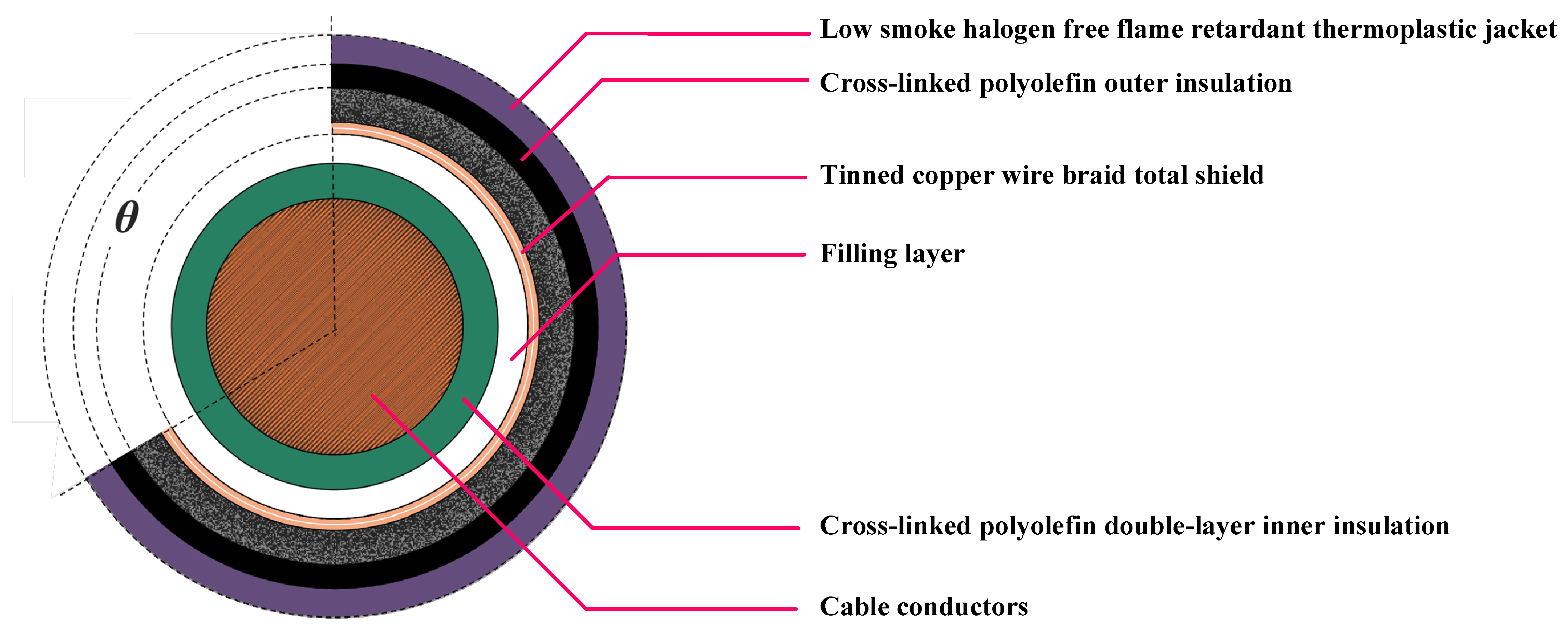
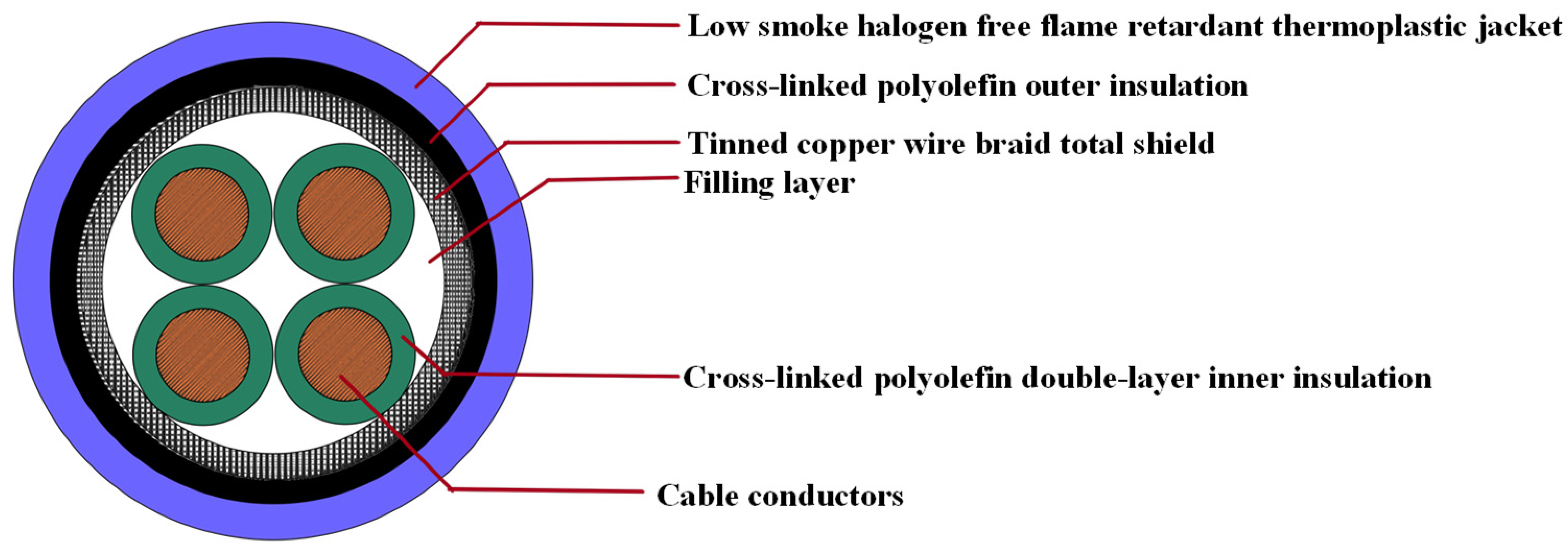
This paper focuses on Class 1E Category K3 cross-linked polyolefin instrumentation cables used in nuclear power plants. The multi-core structure of the I&C cables is shown in Figure 1. Their cross-section materials from the outside to the inside are the outer sheath, the outer insulation, the copper wire braid total shield, the filler layer, the inner insulation, and the tinned copper conductor, respectively.

2.2. Modeling

In the defect detection application working conditions, the I&C cable as a simple centralized parameter system consisting of only the protective layer, insulation and conductive core becomes no longer applicable. It should be regarded as a system with countless electrical units distributed along its length. The distributed parameters should be used as the basis for analyzing its physical model. The equivalent circuit of the cable can be represented by the circuit model of the distributed parameters in Figure 2.
R0, L0, C0, and G0 represent the four unit-electrical elements, series resistance, series inductance, shunt capacitance, and shunt conductance. Δx is the unit length, and U(x) is the voltage at that point. These four basic distributed parameter elements allow for analyzing the transmission characteristics of the signal through the cable.

3. Calculation of Distributed Parameters for Single-Core Nuclear I&C Cables

3.1. Distributed Parameters of Non-Destructive Single-Core Nuclear I&C Cables

The coaxial cable structure also has a “skin effect” between the cable core and the metal shield, which concentrates the core current on the surface of the conductor. As the frequency increases, the skinning depth δ of the conductor will change, as shown in Equation (1).
δ = 2 ρ ω μ 0 μ r
where ρ is the resistivity of the conductor, μ0 and μr are the vacuum permeability and the relative permeability of the conductor, and ω is the angular frequency.
Under the action of the skin effect, the resistance and inductance along the line path of nuclear I&C cables, as well as the capacitance and conductivity between the core and the shield, will change with the change in operating frequency. For a single-core nuclear I&C cable under a coaxial structure, the single-core cable distributed resistance [21] per unit length can be approximated as Equation (2):
R 0 ( ω ) 1 2 π μ 0 ω 2 ( 1 r c ρ c + 1 r s ρ s )
where ρc, ρs are the resistivity of the cable core and shield, respectively. rc is the radius of the cable core; rs is the radius of the cable shield.
The role of the shield is to confine the electromagnetic field between the inner core of the cable and the copper tape shield. The self-inductance between the inner core and the outer shield as well as the mutual inductance together constitute the distributed inductance of the cable. The distributed inductance of the wire core and shield per unit length [21] can be approximated as Equation (3):
L 0 ( ω ) 1 4 π 2 μ 0 ω 1 r c ρ c + 1 r s ρ s + μ 0 2 π ln r s r c
In addition, the parallel conductance and parallel capacitance per unit length of the cable depend mainly on the material properties of the main insulating dielectric layer of the cable and its geometry, and the distributed capacitance of a single-core cable per unit length [22] is calculated as follows (4):
C 0 ( ω ) = 2 π ε 0 ε r ln r s / r c
Due to the dielectric loss of the main insulation of the cross-linked polyolefin of nuclear I&C cables, this will lead to the existence of a certain leakage current from the cable circuit to the outside. So the distributed conductance of a single-core cable per unit length [22] is calculated as follows (5):
G 0 ( ω ) = 2 π ε 0 ε r ω ln r s / r c
In the above two equations, εr and εr are the real and imaginary parts of the relative permittivity of the medium, respectively, and there is a relationship with the complex permittivity (6):
ε = ε r j ε r
Nuclear I&C cables will exhibit different dielectric properties at various frequencies if they are subjected to electric fields of different frequencies, resulting in a change in the frequency characteristics of the dielectric constant of the dielectric. It affects the value of the shunt conductance and shunt capacitance of the cables, which also change with frequency. Therefore, the shunt conductance and shunt capacitance of cables also show a clear frequency dependence.

3.2. Distributed Parameters of Single-Core Nuclear I&C Cables with Broken Shields

For nuclear I&C cables, the breakage of the insulation shielding layer leads to a change in its geometric structure, which in turn leads to a change in the shielding resistance, skinning depth, self-inductance, mutual-inductance, and capacitance effects of the inner and outer conductors in that localized area. If the circumferential angle of the defect is made to be θ and the radial depth of the defect reaches the shield of the cable, the cross-section of a single-core nuclear I&C cable with a broken outer insulation shield is shown in Figure 3.
The distributed resistance of nuclear I&C cables is jointly affected by the resistance of the core and the shield. Shield layer circumferential damage is equivalent to the unit length of the cross-sectional area of a certain degree of reduction, and the degree of reduction and damage circumferential angle θ is proportional. Because the unit length resistance is inversely proportional to its cross-sectional area, while the resistivity of the shielding layer remains unchanged. The outer shield layer breakage will increase the resistance of the shield layer. The shield layer breakage coefficient k1 to measure the degree of change in the resistance part of the resistance through k1, can be coupled with the ratio of changes in θ to the formula. So, the distributed resistance at the breakage can be calculated as in Equation (7):
R 1 1 2 π μ 0 ω 2 ( 1 r c ρ c + k 1 r s ρ s )
In Equation (7), it is necessary to make the rate of change in θ the same order of magnitude as the resistivity, so the shield breakage coefficient k1 can be obtained by Equation (8):
k 1 = 2 π 2 π θ
The self-inductance change in the shield at the breakage is similar to that of the resistance, and the breakage will increase the self-inductance of the conductor there. So, k1 can still be used to indicate the degree of self-inductance change. However, due to the partial loss of the jacket, the shielding layer and the core of the magnetic chain between the coupling will become weaker, that is, the shielding layer and the core of the mutual inductance will be reduced. So, the use of broken mutual inductance coefficient k2 to measure the degree of change in the mutual inductance of the inductance of its inverse of k1, is used to express the loss of the circumferential coupling medium. Therefore, the distributed inductance at the breakage can be calculated as in Equation (9):
L 1 = μ 0 k 2 2 π ln r s r c + μ 0 4 π δ c r c + k 1 δ s r s
In addition, the shield layer damage caused by the geometric structure of the cable changes will also lead to the shield and the core of the capacitive effect between the weakening of the distributed capacitance decreases. The damage of the capacitance coefficient k3 is used to express the degree of change in the unit capacitance and unit conductance of the damage, its expression and the derivation of the damage of the coefficient of mutual inductance are similar. The two values are approximately the same, so that k3 is equal to k2. Therefore, the distribution of the damage at the distributed capacitance and the distributed conductance can be calculated as follows as in Equations (10) and (11):
G 1 2 π ε 0 ε r ω k 3 ln r s r c
C 1 2 π ε 0 ε r k 3 ln r s r c
In Equations (9)–(11), there is an Equation (12) relationship:
k 2 = k 3 = 2 π θ 2 π

4. Distributed Parameter Modeling of Quasi-Coaxial Nuclear I&C Cables

4.1. Field Circuit Analysis of Quasi-Coaxial Nuclear I&C Cables

The axis of the selected cylindrical coordinate system coincides with the axis of the wire-core conductor and its positive direction is the same as the propagation direction of the electromagnetic wave. the offset distance of the axis of the outer shield relative to the axis of the wire-core conductor is defined as the offset core distance. The schematic diagram of any cross-section of a quasi-coaxial cable is shown in Figure 4. Due to the existence of other cores in multi-core cables, and nuclear I&C cables are equipped with an inner insulation layer isolation of each core. For simplicity, ignore the other core conductors of the I&C cables and other braided filler, so that the part outside the single core studied in the shielding layer (the part of the inner conductor to the outer conductor) are all regarded as the same dielectric.
In Figure 4, e is the eccentricity distance. rc and rs denote the radius of the inner and outer conductors, respectively. b denotes the distance from the center of the inner conductor to the outer conductor, which is non-deterministic. a denotes the shortest distance from the inner conductor to the outer conductor. ψ and r denote the circumferential angle and radial distance, respectively, of any point under any cylindrical cross-section and satisfy Equation (13):
r c r b 0 ψ 2 π
According to the cosine theorem for oblique triangles, it can be obtained that b satisfies Equation (14):
b = r s 2 e sin ψ 2 e cos ψ
and there is Equation (15):
r s = e + r c + a
Since the dominant component of the electromagnetic field in the quasi-coaxial cable mainly depends on the radial variable r, the effect due to its variation along the circumferential ψ is negligible. Based on the classical theory of the electromagnetic field, we can obtain the expression of the electromagnetic field equations in the state of the inner conductor in the presence of an eccentric core as in Equations (16) and (17):
H ψ ( r , ψ , z ) = I 2 π r e γ z i ψ
E r ( r , ψ , z ) = U r ln ( r s r c ) 2 e r c sin ψ 2 e r c cos ψ e γ z i r
In a coaxial line, I and U denote the valid value of the current flowing through the conductor and the voltage difference between the inner and outer conductors, respectively. If the eccentricity distance is not zero, the distribution of the instantaneous voltage around the axis exhibits asymmetry, which is different from the conventional theoretical analysis on an ideal coaxial line with zero eccentricity distance. In addition, iψ, ir, and z correspond to the circumferential and radial unit vectors and axial coordinates in the cylindrical coordinate system, respectively, while γ denotes the propagation constant of the electromagnetic wave in the medium.

4.2. Distributed Parameters of Non-Destructive Quasi-Coaxial I&C Cables

For a section of quasi-coaxial cable per unit length, the cross-sectional area of this coaxial cable is S. Assume that the voltage and current between the inner and outer conductors of the cable are Ue ± jβz and Ie ± jβz, respectively. Based on this, we can calculate the average magnetic energy storage Wm per unit length of this section of quasi-coaxial cable as in Equation (18):
W m = μ 4 S H · H d S
where μ is the magnetic permeability of the conductor medium, H is the magnetic field strength, determined by Equation (16). It is the conjugate complex of the magnetic field strength.
According to the circuit principle, it can be given as Equation (19):
W m = 1 4 L I 2
The inductance with cross-sectional area S per unit length can be expressed as Equation (20):
L = μ I 2 S H · H d S
The mutual inductance between the outer shield and the core per unit length can be expressed as Equation (21):
L e = μ ( 2 π ) 2 0 2 π ln ( r s r c ) 2 e r c sin ψ 2 e r c cos ψ d ψ
The core is in the state of the partial core, which does not change the geometry of the inner and outer conductors alone, so the core and shielding layer of the self-inductance are still the same as in Formula (3).
The distributed inductance of the quasi-coaxial cable per unit length can be obtained from Equation (22):
L q 0 = L e + μ 4 π δ c r c + δ s r s
From the classical theory, the average electrical energy storage on a coaxial line per unit length is given by Equation (23):
W e = ε 4 S E · E d S
where ε′ is the real part of the dielectric constant of the medium, E is the electric field strength, determined by Equation (17), and E * is the conjugate complex of the electric field strength.
Equation (24) can also be given based on the circuit principle:
W e = 1 4 C U 2
The capacitance per unit length of cross-sectional area S can be expressed as Equation (25):
C = ε 0 ε U 2 S E · E d S
The distributed capacitance of the quasi-coaxial cable per unit length can be calculated from Equation (26):
C q 0 = ε 0 ε 0 2 π 1 ln ( r s r c ) 2 e r c sin ψ 2 e r c cos ψ d ψ
According to the principle of electromagnetism, when a metal wire has a certain conductivity, its power loss per unit length can be expressed as Equation (27):
P e = R S 2 c 1 + c 2 H · H d S
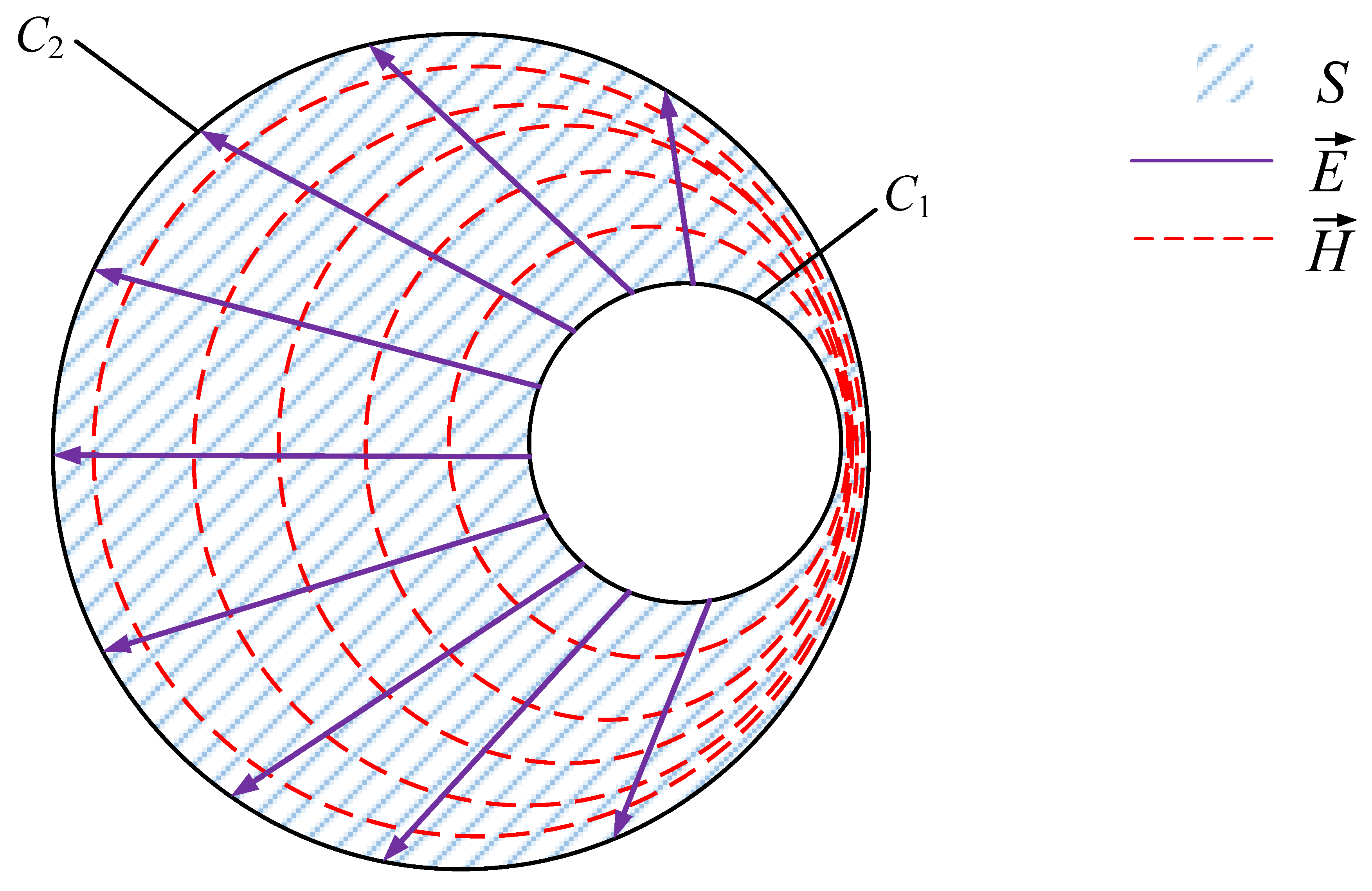
In the above equation, we set the tangential component on the circumference C1 of the inner conductor cable core and the circumference C2 of the outer conductor shield, while C1 + C2 is used to refer to the integration paths of the edges of the inner and outer conductors, as shown in Figure 5.
And RS is used to refer to the surface resistance of the conductor with Equation (28):
R S = ρ δ
where ρ denotes the conductivity of the conductor and δ is the conductor skinning depth.
Equation (29) is also obtained based on the circuit principle:
P e = 1 2 R I 2
Therefore, its series resistance can be expressed as Equation (30):
R = R S I 2 c 1 + c 2 H · H d l
The distributed resistance of the quasi-coaxial cable per unit length can be calculated from the following equation to find Equation (31):
R q 0 = 1 2 π μ ω 2 1 r c ρ c + ρ s 2 π 0 2 π 1 r s 2 e sin ψ 2 e cos ψ d ψ
According to the electromagnetic field theory, the time-averaged power loss of a coaxial cable per unit length within a medium that absorbs energy is expressed in Equation (32):
P d = ω ε 2 S E · E d S
where ε″ is the imaginary part of the dielectric constant of the medium and ω is the angular frequency.
Equation (33) can be obtained from the circuit principle:
P d = 1 2 G U 2
Therefore, its parallel conductance can be expressed as Equation (34):
G = ω ε 0 ε U 2 S E · E d S
The distributed conductance of the quasi-coaxial cable per unit length can be calculated from Equation (35):
G q 0 = ω ε 0 ε 0 2 π 1 ln ( r s r c ) 2 e r c sin ψ 2 e r c cos ψ d ψ
For the analytical formula of the distributed parameter in the off-core state derived above, if the off-core distance of the core is made to be e = 0, the classical analytical solution of the distributed parameter of the ideal coaxial line can be obtained.

4.3. Distributed Parameters of Quasi-Coaxial I&C Cables with Broken Shields

For the multi-core nuclear I&C cable shield breakage defects studied in this paper, the shield breakage coefficient k1, breakage mutual inductance coefficient k2, and breakage tolerance coefficient k3 can also be used to couple. And this can obtain the distributed parameter formulas at the cable breakage under different defect circumferential angles θ, as shown in (36).
R q 1 = 1 2 π μ ω 2 1 r c ρ c + k 1 ρ s 2 π 0 2 π 1 r s 2 e sin ψ 2 e cos ψ d ψ L q 1 = μ k 2 ( 2 π ) 2 0 2 π ln ( r s r c ) 2 e r c sin ψ 2 e r c cos ψ d ψ + μ 4 π δ c r c + k 1 δ s r s C q 1 = k 3 ε 0 ε 0 2 π 1 ln ( r s r c ) 2 e r c sin ψ 2 e r c cos ψ d ψ G q 1 = k 3 ω ε 0 ε 0 2 π 1 ln ( r s r c ) 2 e r c sin ψ 2 e r c cos ψ d ψ
Therein, the shield breakage coefficient k1, the breakage mutual inductance coefficient k2, and the breakage tolerance coefficient k3 are still calculated by Equations (8) and (12). However, due to the multi-core nuclear I&C cables, for the detected wire core, this is not completely symmetrical with the shielding layer. So, the same circumferential breakage angle, the shielding layer relative to a specific core in different locations, and the local characteristic impedance on the core are inconsistent. In order to control the variables, and analyze the mapping relationship between the defect circumferential angle and the local characteristic impedance, the wire core, the jacket, and the breakage defects circumferential angle is the same in the axisymmetric structure, and there is a unique axis of symmetry. And there exists a unique symmetry axis, as shown in Figure 6. In the subsequent numerical analysis, simulation modeling is set in this way to set the location of the broken cable shield.

5. Simulation Study on Shield Breakage Detection of Nuclear I&C Cables

5.1. Characteristic Impedance Analysis of Shield Breakage of Multi-Core Nuclear I&C Cables Based on Theoretical Calculations

The actual parameters of the existing cross-linked polyolefin nuclear I&C cables are derived based on the distributed parameter calculation model derived in the previous section. The characteristic impedance of intact multi-core nuclear I&C cables is calculated using MATLAB 2020b according to different center frequencies. For multi-core cables with different numbers of cores and different core sizes, the eccentricity spacing is inconsistent. Within the range of actual core sizes of the actual nuclear I&C cables, the variation curves of the characteristic impedance with the eccentricity spacing of the normal state partial-core line at a frequency of 10 MHz can be obtained for different partial-core spacings, as shown in Figure 7.
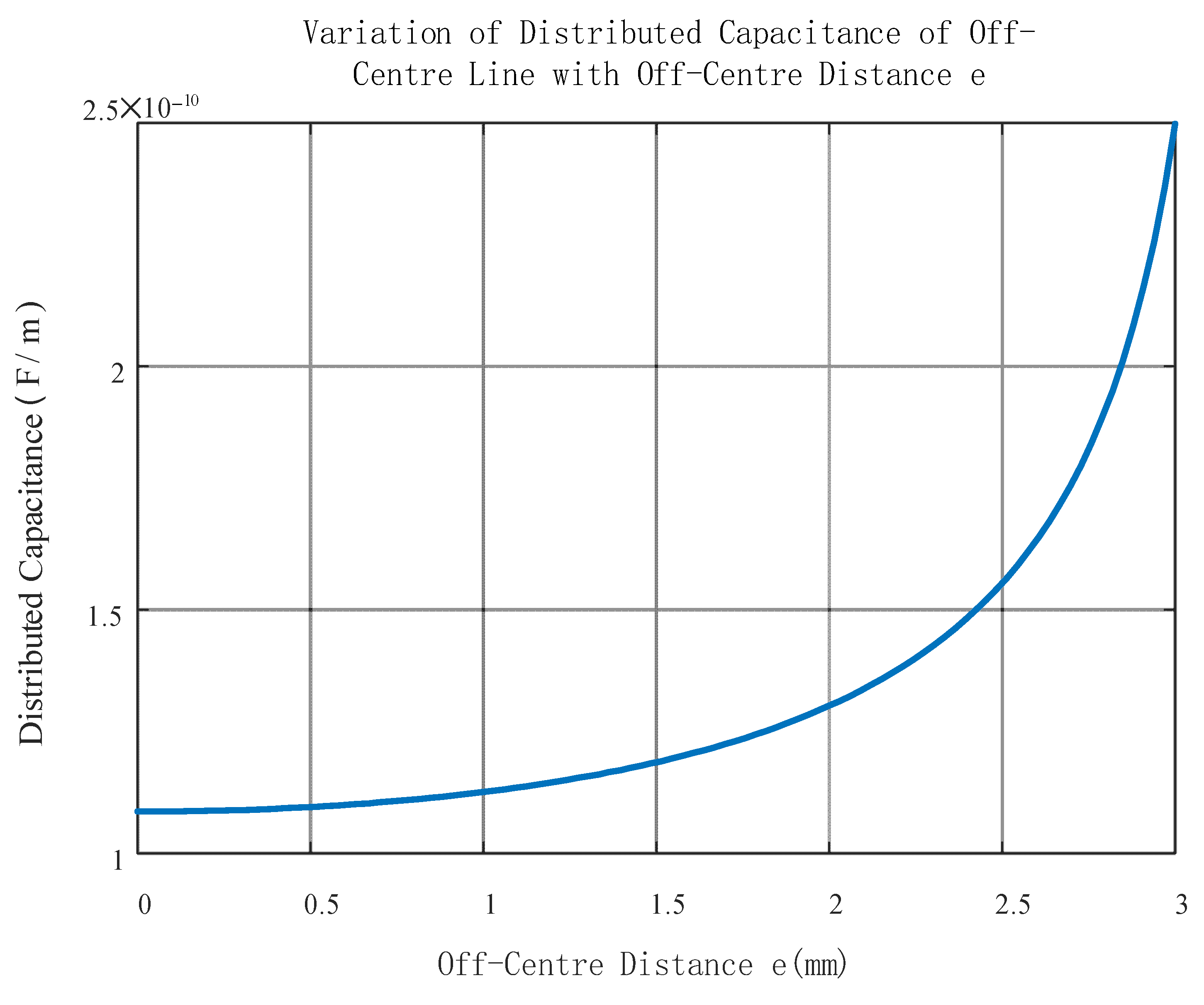
It can be found in Figure 7 that the larger the off-core distance of the inner conductor is, the smaller its characteristic impedance value is. The closer the core is to the edge of the shield, the faster its characteristic impedance decreases. In the high-frequency band, the dominant element of the characteristic impedance is the distributed capacitance, and the variation curve of the distributed capacitance with the offset core distance at 10 MHz is shown in Figure 8. As the offset distance increases, the electromagnetic coupling between the inner conductor of the core and the outer shield is weakened, and the spacing between the inner and outer conductors is shorter. So, the distributed capacitance increases, and therefore the characteristic impedance decreases with the increase in the offset distance.
According to the size of the actual spare four-core nuclear I&C cables studied in this paper, it is determined that the offset core distance e = 2.57 mm, in which the curve of the characteristic impedance of the offset core nuclear I&C cables with the change in frequency can be obtained. The horizontal axis is displayed in logarithmic scale, as shown in Figure 9. When the frequency increases, its characteristic impedance gradually decreases and gradually stabilizes at 37.795 Ω.
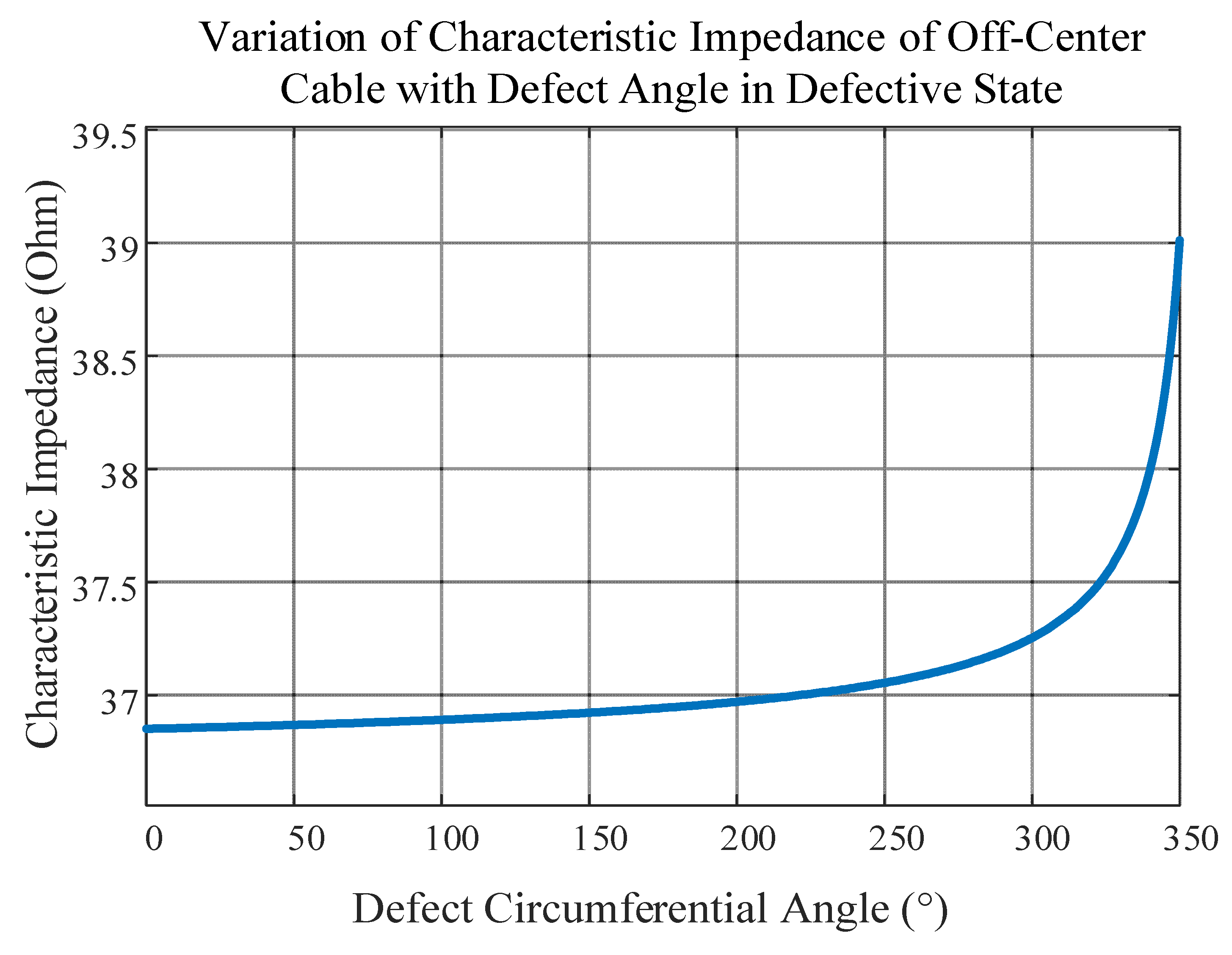
In order to measure the effect of different severities of cable outer shield breakage on the signal transmission characteristics, the variation curves of quasi-coaxial characteristic impedance values with the defect circumferential angle θ at a frequency of 10 MHz are calculated, as shown in Figure 10. With the established cable distributed parameter model for a specific defect circumferential angle, the breakage coefficient changes as θ increases, resulting in a corresponding increase in the characteristic impedance at that location.

5.2. Characteristic Impedance Analysis of Shield Breakage of Nuclear I&C Cables Based on Finite Element Simulation

In order to explore the correctness of the simplified mathematical modeling of the characteristic impedance of I&C cables, to carry out more accurate physical modeling and obtain the error of the simplified mathematical model and the physical simulation model, in view of the defects of the shielding layer breakage, the four-core crosslinked polyolefin I&C cables are selected as the object of study, and a two-dimensional model of the biased-core I&C cables and the four-core I&C cables are constructed using finite-element simulation software. And then the finite-element method is used to carry out the electromagnetic field- temperature field coupling simulation using the finite element method.
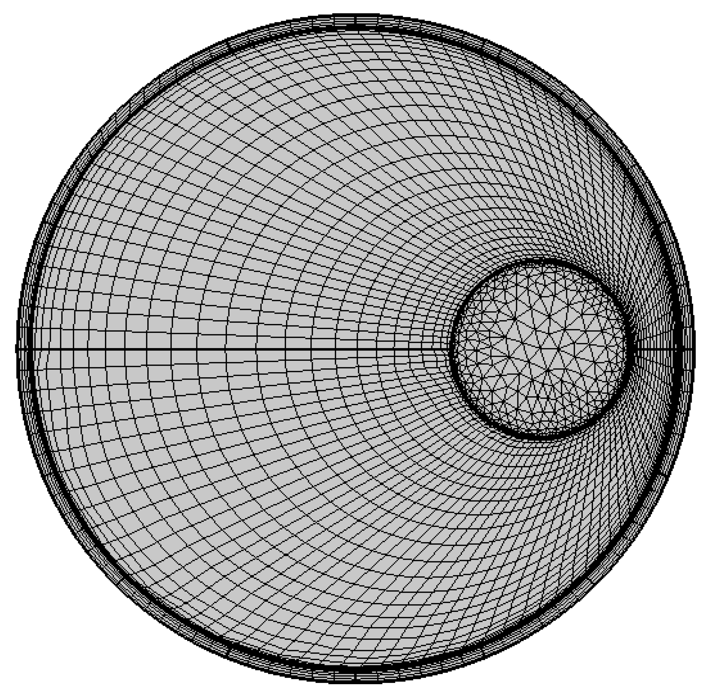
For the quasi-coaxial cable structure, a two-dimensional model can be built in the finite element simulation software, with it taking the core conductor into account, and that the outer shield is filled with cross-linked polyolefin insulating material between the layers, as shown in Figure 11.
In this case, for the actual spare nuclear I&C cables, a piece of the cable section was cut out using a tool and its specific geometrical dimensions were measured, including the radius of each layer of the cable structure as well as the length of the cable. The various parameters used for the cable structure in the simulation modeling are shown in Table 1. The dimensional parameters and some environmental variables configured for the simulation structure are shown in Table 2.
After determining the dimensional structure, material properties and environmental parameters of the nuclear I&C cables, the magnetic field (mf) and electric field (ec) are introduced to set the electromagnetic properties of each structure of the cables, including the domain circling of Ampere’s Loop Laws and the Current Conservation Laws. Finish the boundary setting of the magnetic and electric insulation, the setting of the electromagnetic initial value for each domain, the setting of determining the energizing coils and the termination with the grounding. Finally, electromagnetic wave and frequency domain fields (emw) are added for the domain circling of the fluctuation equations and impedance boundary condition setting to establish the dynamic link between the variables in the frequency and electromagnetic fields.
Once the conditions for each field are set, the relevant physical field interfaces can be invoked to calculate each parameter in the distributed parameter model using the underlying universal equations, and finally, the characteristic impedance values are calculated. The parallel conductance and capacitance can be derived based on the current interface, and the conductor can be considered as a system with a uniform potential. In order to construct the physical field, a voltage U0 is applied to the inner conductor while the outer conductor is grounded. In this way, the potential distribution in the dielectric can be solved.
In order to perform finite element analysis efficiently, the created simulation model must be properly meshed. This process is aimed at decomposing the complex model into multiple simple units, thus facilitating the computational analysis. The quality of meshing has a direct impact on the accuracy and efficiency of the computational results. Too high a meshing density may significantly increase the computational effort and thus prolong the processing time; conversely, too sparse a mesh may weaken the accuracy and convergence of the computation. Therefore, according to the core placement characteristics of the quasi-coaxial cable, the mesh is partitioned using free triangles for the inner conductors of the core, and the mesh is mapped using guidelines for the other regions, as shown in Figure 11.
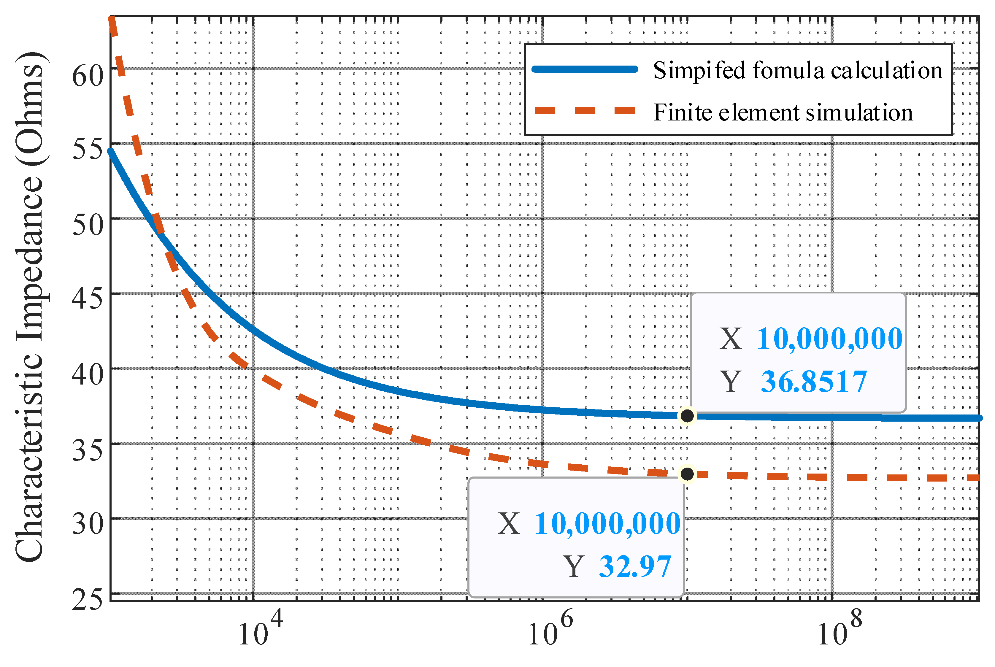
Through the finite element calculation, the variation curve of the characteristic impedance value with the frequency of nuclear I&C cables under the partial core structure can be obtained, as shown in Figure 12, and the theoretically calculated curves are added together in the figure for comparison.
It can be found that the trend in the characteristic impedance calculated by finite element simulation is consistent with the theoretical curve, which can reach stability in the high-frequency band. The theoretical value is 3.88 Ω different from the simulated value at 10 MHz of frequency, so it can be assumed that the simplified formula derived is basically correct.
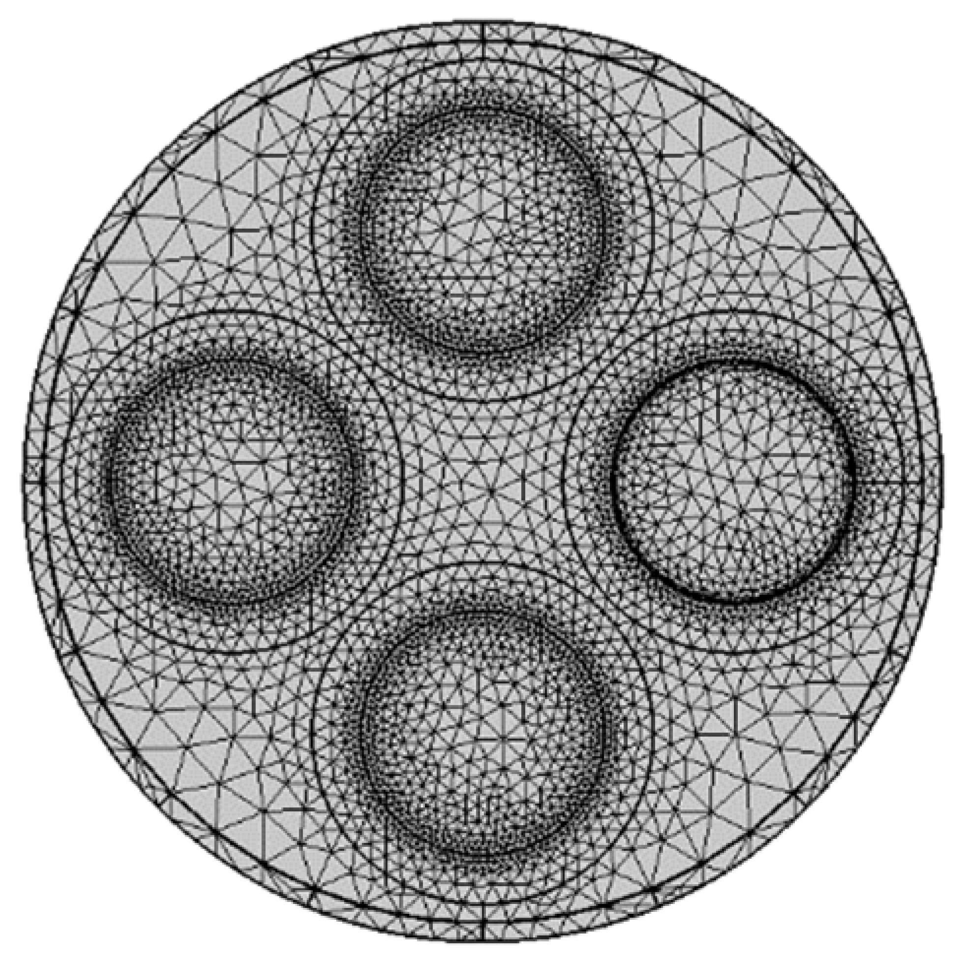
In a multi-core nuclear I&C cable with a common shield, after energizing in one core, the conductors of other cores will cause certain crosstalk [23,24], and the specific electromagnetic field distribution will be different. In order to more accurately simulate the characteristic impedance of the actual nuclear I&C cables, a two-dimensional model of the cross-section of a four-core cable is constructed in the following manner, as shown in Figure 13. The filler material properties and related dimensions are shown in Table 3 and Table 4.
Due to the detection environment of the time-frequency domain detection method, it is necessary to energize only one of the cores of the four-core cable in the electric field node, so that it forms an electrical circuit with the shield. For the cable model with a multi-core structure, in order to facilitate the handling of the filler layer, the simulation uses free triangles to split the mesh for all domains, as shown in Figure 13.
The characteristic impedance of one of the cores of the four-core cable under normal conditions is obtained by using finite element calculations using the interfaces and formulas discussed above, and its curve with its frequency is shown in Figure 14. Among them, the values of the characteristic impedance at each frequency for three different calculation scenarios are shown in Table 5.
It can be found that the stable characteristic impedance in the high-frequency band is 1.68 Ω lower than that of the single-core quasi-coaxial structure after taking into account the specific multi-core structure, which is caused by several factors. Firstly, in multi-core cables, high-frequency signals circulate between the through-core and the reverse loop of the outer shield. The non-through-core generates weak currents due to electromagnetic induction, which increases the capacitive effect on each conductor due to the fact that the multiple conductors are relatively close to each other. Secondly, the presence of multiple conductors will reduce the magnetic chain coupling between the energized core and the outer shield, so it will slightly reduce the mutual inductance effect per unit length. However, the effect of inductance on the characteristic impedance is usually less pronounced than that of capacitance. If the distance between the energized core of the multi-core cable relative to the center and the eccentricity of the quasi-coaxial line are equal, the characteristic impedance of the multi-core cable is generally lower than that of the single-core cable.
In order to verify the correctness of the characteristic impedance of the four-core cables calculated by simulation, the short section (1 m) of the spare four-core nuclear I&C cables of the actual nuclear power plant is detected by using the network analyzer of Steady Tech WK6500B for the detection of the characteristic impedance. The maximum detection frequency of this model of the network analyzer is 5 MHz, and the characteristic impedance value of this segment is obtained as 32.384 Ω. By checking the characteristic impedance values calculated by each method in Table 5, the values calculated by each method and the error rate relative to the detection value of the network analyzer can be obtained in this frequency band, as shown in Table 6. Among them, the values calculated by the finite element simulation of the biased-core line and the four-core line are closer to the detection results, and the errors of both are smaller and of equal magnitude.
It can be seen that the finite element simulation model constructed in this paper more correctly reflects real nuclear I&C cables, and is more capable of correctly calculating the characteristic impedance value of the four-core cable under specific working conditions. Taking into account that the actual spare cable storage time is longer, the metal conductor part may cause part of the oxidation, and a little aging phenomenon may also appear in the insulation layer, it is considered that the actual intact four-core nuclear I&C cable’s real characteristic impedance value should be smaller than the value detected by the network analyzer. It is considered that the four-core finite element simulation of the calculated value should be the closest to the real situation. Therefore, in the following shielding layer breakage, thermal stress is cited in the model and defect detection simulation experiments. For the cable characteristic impedance setting, we use the results calculated by the four-core finite element simulation model.
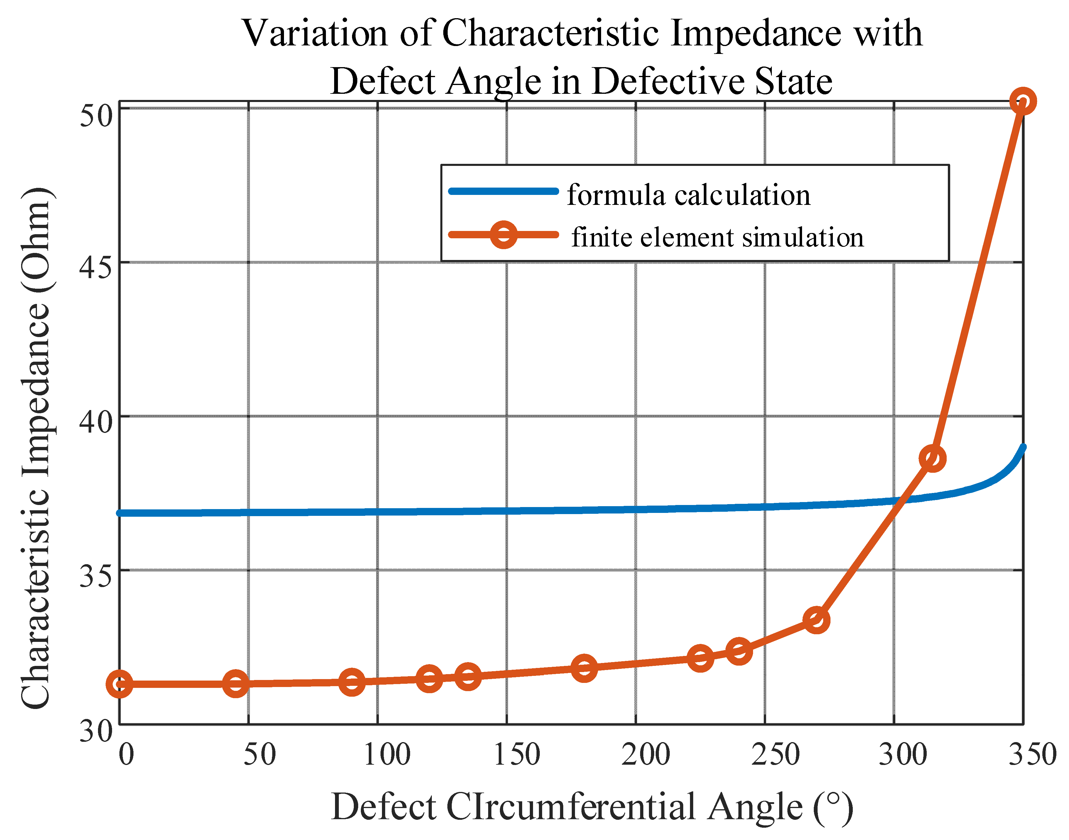
In order to investigate the effect of the breakage of the outer insulation shield of nuclear I&C cables on their characteristic impedance, the material properties of some outer conductors in the four-core cable model are changed to simulate the breakage of different severities and are associated with the defect circumferential angle θ. The defect simulation rule is shown in Figure 6, so that the outer insulation shield is in an axisymmetric structure with a unique axis of symmetry. Taking the defect simulation rule in Figure 6 into account, the wire core, the jacket, and the circumferential angle of the broken defects are in the same axisymmetric structure, and there exists a unique axis of symmetry. In order to ensure the uniformity of the frequency, the simulation of different defect severities is set to be carried out in the environment with a frequency of 10 MHz. The effects of different defect circumferential angles on the characteristic impedance of four-core nuclear I&C cables can be obtained, as shown in Figure 15. The data of the characteristic impedance values calculated by the simplified formula under damage and calculated by the finite element simulation are demonstrated in Table 7.
From Figure 15, it can be found that the simulated characteristic impedance value also increases with the increase in the defect circumferential angle θ. When the defect circumferential angle is less than 270°, the difference between the calculated models is small, the difference can be controlled within 4 Ω, and the trend in change is the same.
6. Conclusions

This paper establishes a single-core distributed parameter model under defects by introducing the defective circumferential angle. Based on this, it further builds a quasi-coaxial distributed parameter model to approximate the simulation of the four-core model, and simulates and verifies the mathematical model in this paper. It draws the following conclusions:
(1)
After calculating and simulating the calculation model of characteristic impedance, this study finds that when the eccentricity distance e equals 2.57 mm, the characteristic impedance of a 1 m I&C cable gradually decreases and tends to stabilize to 37.795 Ω when the frequency increases.
(2)
Through simulation calculation, it is found that the quasi-coaxial characteristic impedance trend is consistent with the theoretical curve. In the frequency of 10 MHz, the theoretical calculated value is 36.85 Ω and the simulation calculated value is 32.97 Ω, which amounts to a difference of 3.88 Ω. This verifies the correctness of the quasi-coaxial model calculations.
(3)
The characteristic impedance of the quasi-coaxial cable calculation model, quasi-coaxial cable finite element simulation model, and four-core cable finite element simulation model are simulated in the frequency of 5 MHz. It is found that the finite element simulation of the characteristic impedance of the eccentric line cable and the finite element simulation of the four-core cable can be controlled with an error of less than 3%. This validates the use of a quasi-coaxial model equivalent to the four-core cable.
(4)
After comparing results of the model calculation and finite element simulation of cables with different breakage circumferential angles, it is found that the difference can be controlled within 4 Ω in the frequency of 10 MHz when the defect circumferential angle is less than 270°. This proves that the model can be applied to the characteristic impedance calculation of broken cables.
In summary, this paper verifies the correctness and reasonableness of the model for calculating the characteristic impedance of the shield breakage of multi-core nuclear I&C cables. For multi-core nuclear I&C cable shield damage, characteristic impedance calculation provides effective theoretical support.

Author Contributions

Methodology, L.L.; Software, L.L.; Formal analysis, Y.C.; Investigation, C.P.; Resources, H.T., C.P. and H.D.; Writing—original draft, Y.C.; Writing—review & editing, G.L.; Supervision, H.D.; Project administration, H.T. and G.L. All authors have read and agreed to the published version of the manuscript.

Funding

This research was funded by the Suzhou Thermal Engineering Research Institute Co, contract number: 029-GB-B-2021-C45-P.T.99-00074.

Data Availability Statement

The original contributions presented in the study are included in the article, further inquiries can be directed to the corresponding author.

Conflicts of Interest

Author Hua Tu was employed by the company Suzhou Nuclear Power Research Institute Co., Ltd. Author Chao Peng was employed by the company Daya Bay Nuclear Power Operations and Management Co., Ltd. The remaining authors declare that the research was conducted in the absence of any commercial or financial relationships that could be construed as a potential conflict of interest.

References

  1. Fu, Y.; Han, W.; Hou, W.; Li, J. Discussion on Technical Inspection and Management of Nuclear Power Cable. Electr. Technol. Intell. Build. 2023, 17, 16–20,25. [Google Scholar]
  2. Yang, J.; Jin, S.; Yao, Y.; Chen, Y.; Wang, X.; Hong, Q. Study on the Immersion Test of Class-1E Cable in Nuclear Power Plant. Nucl. Sci. Eng. 2021, 41, 784–789. [Google Scholar]
  3. Du, Z. The Improvement and Optimization for the Cable-laying Design of Units 3 and 4 of Tianwan Nuclear Power Plant. China Nucl. Power 2020, 13, 810–815. [Google Scholar]
  4. He, Q.; Zhang, H. Research on Optimization of Instrumentation and Control Cables in Nuclear Power Plants. Process Autom. Instrum. 2023, 44(Suppl. S1), 100–103,108. [Google Scholar]
  5. Lei, C.; Gao, F.; Yang, L.; Li, L. Analysis and Research on Monitoring Index of Aging Status of Low voltage Cable in the Nuclear Power Plant. Electrotechnology 2023, 1, 132–134,137. [Google Scholar]
  6. Lai, Z.; Luo, Z.; Zhang, S.; Wu, W.; Lin, S. Analysis of the process and causes of insulation breakdown of high-voltage cables in nuclear power plants. Equip. Manag. Maint. 2021, 16, 55–56. [Google Scholar]
  7. Chen, Y.; Xu, Z.; Yan, S. Study on Quantitatively Evaluate Situation Assessment Reliability in Digital NPPs Based on Fuzzy Logic Approach. IEEE Access 2022, 10, 36662–36671. [Google Scholar] [CrossRef]
  8. Dong, H.; Zhang, R.; Wang, X.; Jin, K.; Gao, Y. Research on Fault Diagnosis Method of Power Cable Network Based on Time Domain Reflectometry. Comput. Meas. Control 2024, 32, 30–36. [Google Scholar]
  9. Cao, Y.; Zhou, K.; Meng, P.; Jin, Y.; Wang, Y. Cable Defect Location Based on Orthogonal Matching Pursuit and Pseudo Wigner-Ville Distribution. Trans. China Electrotech. Soc. 2023, 38, 4489–4498. [Google Scholar]
  10. Rao, X.; Xu, Z.; Long, L.; Li, Y.; Yang, Y.; Gou, Y.; Ding, Y.; Feng, Y.; Zhou, K. Cable Defect Time Domain Diagnostic Characteristic Waveform Based on Frequency Domain Reflection. Power Syst. Technol. 2023, 47, 3483–3493. [Google Scholar]
  11. Rao, X.; Zhou, K.; Xie, M.; Liu, L.; Wang, X.; Ye, B. Recovery Technique of Characteristic Time Domain Waveform Based on Frequency Domain Reflection Method. High Volt. Eng. 2021, 47, 1420–1427. [Google Scholar]
  12. Li, R.; Zhou, K.; Wan, H.; Xie, M.; Liu, L.; Wang, X.; Ma, X. Moisture Location of 10 kV Cable Joints in Medium Voltage Distribution Grid Based on Frequency Domain Reflection. Power Syst. Technol. 2021, 45, 825–832. [Google Scholar]
  13. Wang, Y.; Yao, Z.; Xie, W.; Wu, J.; Han, Y.; Yin, Y.; Zhao, G. Research on Fault Location of High Temperature Superconducting Cable Based on Time-frequency Domain Reflectometry. Proc. CSEE 2021, 41, 1540–1547. [Google Scholar]
  14. Yuzhe, F. Research on Cable Online Monitoring Method Based on Time-Frequency Domain Analysis. Master’s Thesis, Xi’an University of Technology, Xi’an, China, 2 April 2024. [Google Scholar]
  15. Bang, S.S.; Kwon, G.-Y. Reinforcement Learning-Based Automation of Time-Frequency Domain Reflectometry. IEEE Trans. Ind. Electron. 2024, 71, 4171–4180. [Google Scholar] [CrossRef]
  16. Bang, S.S.; Lee, Y.H.; Shin, Y.-J. Defect Detection in Pipelines via Guided Wave-Based Time–Frequency-Domain Reflectometry. IEEE Trans. Instrum. Meas. 2021, 70, 9505811. [Google Scholar] [CrossRef]
  17. Judith, H.S.I.; Cocquempot, V.; Degardin, V. Fault detection and localization in unshielded twisted pair cable based on observability analysis and reflectometry experimental measurements. Meas. Sci. Technol. 2023, 35, 015034. [Google Scholar] [CrossRef]
  18. Sommervogel, L. Various Models for Faults in Transmission Lines and Their Detection Using Time Domain Reflectometry. Prog. Electromagn. Res. C 2020, 103, 123–135. [Google Scholar] [CrossRef]
  19. Lee, Y.H.; Shin, Y.-J. Time-Frequency Domain Reflectometry for Live HTS Cable System via Inductive Couplers and Neural Network. IEEE Trans. Appl. Supercond. 2021, 31, 5400305. [Google Scholar] [CrossRef]
  20. Lee, H.M.; Kwon, G.-Y.; Bang, S.S.; Shin, Y. Industrial Applications of Cable Diagnostics and Monitoring Cables via Time–Frequency Domain Reflectometry. IEEE Sens. J. 2021, 21, 1082–1091. [Google Scholar] [CrossRef]
  21. Zhang, K.-W. Research on the Diagnosis of Cable Electric Tree Aging Defects Based on Power Line Carrier Communication Technology; Xi’an University of Technology: Xi’an, China, 2024. [Google Scholar]
  22. Yixuan, S. Research on Cable Defect Detection and Location Method Based on Impedance Spectrum. Master’s Thesis, Northeast Electric Power University, Jilin, China, 1 November 2024. [Google Scholar]
  23. Juhao, F. Research on Transmission Line Crosstalk Method Based on Multi-Conductor Transmission Line Theory; Nanjing Normal University: Nanjing, China, 2022. [Google Scholar]
  24. Yan, L.; Leijie, Q.; Yunpeng, L. Communication Channel Analysis of Three-core Medium-Voltage Cable with Common Shielding Layer. High Volt. Electr. Appar. 2020, 56, 101–106,113. [Google Scholar]
Figure 1. Class 1e I&C Cable’s Multi-Core Construction.
Energies 18 03008 g001
Figure 2. Distributed parameter equivalent circuit model.
Energies 18 03008 g002
Figure 3. Cross-section of nuclear I&C cables with broken insulation shields.
Energies 18 03008 g003
Figure 4. Geometric structure of quasi-coaxial schematic.
Energies 18 03008 g004
Figure 5. Electric and magnetic field distribution in the cross-section of a quasi-coaxial cable.
Energies 18 03008 g005
Figure 6. Quasi-coaxial cable shield breakage location setting.
Energies 18 03008 g006
Figure 7. Variation curves of characteristic impedance of normal quasi-coaxial I&C cables with offset core distance.
Energies 18 03008 g007
Figure 8. Curve of distributed capacitance of normal quasi-coaxial nuclear I&C cables with offset core distance.
Energies 18 03008 g008
Figure 9. Characteristic impedance versus frequency curves for normal quasi-coaxial nuclear I&C cables.
Energies 18 03008 g009
Figure 10. Variation curves of characteristic impedance at local defects of quasi-coaxial nuclear I&C cables.
Energies 18 03008 g010
Figure 11. Schematic of 2D model of simulation software for nuclear I&C Cables with partial core structure.
Energies 18 03008 g011
Figure 12. Characteristic impedance versus frequency curves of quasi-coaxial nuclear I&C cables under two methods.
Energies 18 03008 g012
Figure 13. Schematic of 2D model of simulation software for four-core structural nuclear I&C cables.
Energies 18 03008 g013
Figure 14. Characteristic impedance versus frequency curves of nuclear I&C cables under three methods.
Energies 18 03008 g014
Figure 15. Variation curves of characteristic impedance of nuclear I&C cables with defect circumferential angles in two cases.
Energies 18 03008 g015
Table 1. Material parameters of the simulation model for partial-core nuclear I&C cables.
QuantityOptoelectronics/CopperInsulation Layer
Relative Dielectric Constant12.25 − j0.01
Relative Permeability11
Conductivity S/m5.98 × 1070
Density kg/m38940900
Constant Pressure Heat capacity J/(kg·K)3852302
Thermal Conductivity w/(m·K)4000.4
Table 2. Simulation model structure and environmental parameters of off-center nuclear I&C cables.
Simulation ParametersValue
Core Radius (mm)1.25
Radius of Shielding Layer (mm)4.5
Shield Thickness (mm)0.2
Conductor Offset Distance (mm)2.57
Applied Voltage (V)1
Applied Current (A)1
Temp (°C)0
Table 3. Additional material parameters for the simulation model of four-core nuclear I&C cables.
MaterialRelative PermittivityRelative PermeabilityConductivity (S/m)Densities (kg/m3)Constant Pressure Heat Capacity (J/(kg·K))Thermal Conductivity (W/(m·K)
Filler Layer2.25−j0.0110925000.22
Table 4. Additional structural parameters of simulation model for four-core nuclear I&C cables.
Simulation ParametersValue
Inner Insulation Thickness (mm)0.5
Inner Insulation Layer Radius (mm)1.75
Table 5. Characteristic impedance values of nuclear I&C cables for three methods in different frequency bands.
Frequency (MHz)Calculated Values of Simplified Formula for Off-Center Cable (Ω)Finite Element Calculated Values for Off-Center Cable (Ω)Finite Element Calculated Values for Four-Core Cable (Ω)
0.00154.8064.5267.15
0.00545.0642.4442.65
0.0142.5939.8439.40
0.0539.2836.6035.33
0.138.5035.6734.20
0.537.4834.0332.42
137.2433.6332.02
536.9333.1031.44
1036.8532.9731.31
5036.7532.8031.13
10036.7232.7631.09
50036.7032.7231.04
100036.6932.7231.04
Table 6. Characteristic impedance values of nuclear I&C cables obtained by three methods at 5 MHz and their errors with respect to the actual values.
Calculation MethodCharacteristic Impedance (Ω)Inaccuracy (%)
Simplified Formula for Bias-Core Wires36.9314.04
Finite Element Simulation of Eccentric Wires33.102.21
Finite Element Simulation of Four-Core Wire31.442.92
Table 7. Characteristic impedance values of nuclear I&C cables with different defect severities in both cases.
Defect Circumferential Angle (°)Calculated Values of Simplified Formula for Bias Cores (Ω)Finite Element Calculated Values for Four Core (Ω)
4536.8731.32
9036.8831.37
12036.9031.48
13536.9131.55
18036.9531.82
22537.0132.14
24037.0332.37
27037.1133.38
31537.3938.63
35039.0150.23
Disclaimer/Publisher’s Note: The statements, opinions and data contained in all publications are solely those of the individual author(s) and contributor(s) and not of MDPI and/or the editor(s). MDPI and/or the editor(s) disclaim responsibility for any injury to people or property resulting from any ideas, methods, instructions or products referred to in the content.