1. Introduction
Oil shale, an unconventional oil and gas resource, has received considerable attention due to its substantial reserves and high potential for development and utilization [
1]. The oil content of oil shale, as measured by tests, is far greater than 3.5% [
2], and the rock is rich in kerogen organic matter, which is an immature hydrocarbon source. During the process of obtaining cracked oil, the calorific value of oil shale generally exceeds 4180 J/kg [
3]. Currently, in situ conversion extraction is considered the optimal method for oil shale exploitation, which involves subjecting the reservoir to high-temperature heating to transform the solid kerogen in the oil shale into shale oil and gas and then extracting it from underground to the surface [
4]. Heat injection plays a crucial role in the in situ extraction process of oil shale, and there are two main methods of heat injection: downhole heating and surface heating [
5]. Downhole heating typically involves the use of downhole heaters to directly generate high-temperature heat sources to heat the target oil shale layer, thereby producing shale oil and gas. Surface heating, on the other hand, utilizes heaters to generate high-temperature heat sources, which are then transported to the target oil shale formation through heat-resistant gas pipelines to heat the formation and facilitate the production and recovery of shale oil and gas [
6].
In thermal injection processes, the application of heaters constitutes a core component; however, while they provide a high-temperature heat source, they are subjected to significant thermal loads [
7]. Specifically, due to the action of high-temperature thermal stresses, the heater material may experience cumulative damage phenomena, such as high-temperature creep, microstructural damage (e.g., grain boundary sliding or dislocation multiplication), and micro-deformation, ultimately leading to fatigue failure [
8]. The primary cause of fatigue damage in downhole heaters is the thermal stress induced by the non-uniform distribution of the temperature field during their operational cycles, particularly during phase transitions such as heater startup, operation, and shutdown, where significant temperature gradient changes lead to pronounced thermal stress. Within a single start–stop cycle, the interface between the heater and the high-temperature heat transfer medium is subjected to repeated compressive and tensile alternating thermal stress [
9]. If the rate of temperature change in the heat transfer medium is too rapid, or if the heater experiences severe thermal shocks (high temperature) and cold shocks (low temperature), the peak cyclic thermal stress can easily approach or even exceed the material’s yield strength, thereby inducing significant plastic deformation and directly shortening the heater’s fatigue life. On the other hand, even when the cyclic stress amplitude remains consistently below the material’s yield limit, and even below its elastic limit, sustained cyclic thermal stress can still lead to fatigue damage. This damage manifests as the gradual accumulation of permanent micro-damage at specific locations within the material (such as defects or stress concentration areas). After a sufficient number of cycles, this damage propagates to form cracks, ultimately resulting in fatigue fracture. Therefore, to ensure the safe and efficient operation of thermal injection projects and to prevent potential engineering failures, it is crucial to accurately predict the fatigue life of heaters under specific operating conditions [
10]. This necessitates the comprehensive consideration of multiple factors, including the mechanical properties of the selected structural material, the specific operating temperature conditions, and the temperature variation history (temperature cycling), to establish effective fatigue life prediction models. Such models provide a theoretical basis and technical support for engineering practice.
Currently, researchers worldwide focus their studies on fatigue life from aspects such as material usage, structural design and optimization, and stress and strain under cyclic loading, temperature, and pressure. Gao et al. [
11] employed finite element codes to combine heat transfer, phase transformation, and thermo-elastic plastic deformation in the scientific issues of reservoir exploitation but did not specifically address the fatigue life of metallic materials. Post et al. [
12] investigated composite structural materials, analyzed the relationship between stress and loading cycles through constant amplitude loading, and derived failure cycles to evaluate fatigue life but did not consider variable amplitude loading and temperature effects. Zhu et al. [
13] proposed a new fatigue life prediction model, compared its prediction accuracy with various models, and analyzed the effects of mean stress and ratcheting but did not consider temperature factors. Sun et al. [
14] studied the high-cycle fatigue crack origin of high-strength steel using 20 kHz ultrasonic fatigue tests and proposed a two-parameter prediction model based on inclusion size, but the conclusions were based solely on stress amplitude changes and did not consider high-temperature effects. Ladani et al. [
15] investigated the influence of intermetallic compounds in solder on the mechanical behavior, thermo-mechanical fatigue life, and reliability of solder interconnects, using the Coffin–Manson model to evaluate life; however, they considered thermal effects without in-depth analysis. Sharma et al. [
16] studied the life of metallic materials under high-cycle and ultra-high-cycle fatigue conditions through statistical analysis but did not explore the influence of temperature factors. Hiroyuki et al. [
17] analyzed the fatigue life of YSZ thermal barrier coatings and the influence of substrate coating mechanical properties; however, although they reported experimental results at room temperature and 620 °C, they did not analyze temperature as the main variable. Wang et al. [
18] predicted the fatigue life of thin-walled structures based on an improved rain flow counting method and Miner’s theory and analyzed the effects of cyclic stress, thermal modal frequency, and material fatigue resistance, but the temperature range was limited (50 °C~250 °C) and the researchers did not consider higher temperatures. Su et al. [
19] studied the fatigue life law of 308 L weld metal at 300 °C and 8 MPa, but the study was limited to a single temperature. Tan et al. [
20] introduced principal component analysis at high temperatures of 760 °C and 980 °C to determine the critical plane dominant damage factor and established a life model, but the study lacked experimental verification. Although the existing literature has discussed the effects of factors such as stress amplitude, temperature, stress–strain, and composite materials on fatigue life, few studies [
21,
22,
23] have considered the fatigue life problem of heaters under variable amplitude and ultra-high-temperature conditions in the in situ conversion and exploitation of oil shale.
Given that oil shale is a significant unconventional energy resource, the feasibility and economic viability of its in situ conversion and extraction technologies are largely contingent upon the reliability and lifespan of the core equipment—the combustion heater. Operating under harsh downhole conditions characterized by high temperatures and cyclic loading, potential failures of the heater not only lead to substantial economic losses, such as high costs associated with operational downtime and maintenance, but they also pose severe safety risks. Therefore, the precise prediction and assurance of the heater’s fatigue life hold direct and substantial practical significance for enhancing the stability, reliability, and economic efficiency of the entire extraction process, as well as for safeguarding energy supply security. The predictive results obtained through simulation analysis in this study provide a necessary theoretical basis and scientific support for optimizing heater design and formulating scientifically sound and rational operational and maintenance strategies.
3. Fatigue Life Analysis of the Heater
The performance of the heater is one of the key indicators for evaluating the in situ conversion mining of oil shale. While the heater transfers heat carriers to the oil shale stratum, thermal-induced stresses, heat accumulation, thermal shocks, thermal deformation, and thermal expansion can cause certain thermal damage to the heater’s structure. Additionally, these factors significantly impact the fatigue life of the heater. By combining actual operational experiments and taking the exhaust gas temperature as the primary consideration, this paper mainly analyzes the damage and failure of the heater caused by the thermal effects of thermal stress and thermal shocks [
29].
3.1. Fatigue Failure Life Analysis
Determining whether the maximum thermal stress generated during the operation of the heater can cause significant plastic deformation of the structural material under a single maximum load and lead to failure by reaching the material’s compressive limit is one of the primary bases for analyzing the heater’s lifespan. This paper uses the thermal stress generated by high-temperature heat flow as the main analytical basis and employs ABAQUS 6.12 to analyze the impact of the thermal stress on the combustion chamber and the metal gasket when the exhaust gas temperature ranges from 400 °C to 700 °C. Since the stress–strain relationship is one of the most critical factors in determining material fatigue failure, the changes in thermal stress and the amount of microscopic deformation on the heated surfaces of the combustion chamber and metal gasket need to be considered.
Due to the thermal stress acting on the combustion chamber, the contour plots of wall thermal stress and microscopic deformation are shown in
Figure 3. Therefore, when the exhaust gas temperature ranges from 400 °C to 700 °C, the relationship between the wall thermal stress of the combustion chamber and the heating path is depicted in
Figure 4a; the relationship between the microscopic deformation of the combustion chamber wall and the heating path is illustrated in
Figure 4b.
As indicated in
Figure 4, the trends of thermal stress and microscopic deformation in the combustion chamber are consistent, and both increase continuously with the rise in temperature, with the maximum thermal stress concentration and the location of wall microscopic deformation occurring at the same position. Therefore, further analysis of the relationship between the area of maximum thermal stress concentration and the location of wall microscopic deformation on the combustion chamber wall at 400–700 °C is required. The results are presented in
Figure 5a and
Table 3, and the stress–strain relationship at this location in the combustion chamber is analyzed as shown in
Figure 5b.
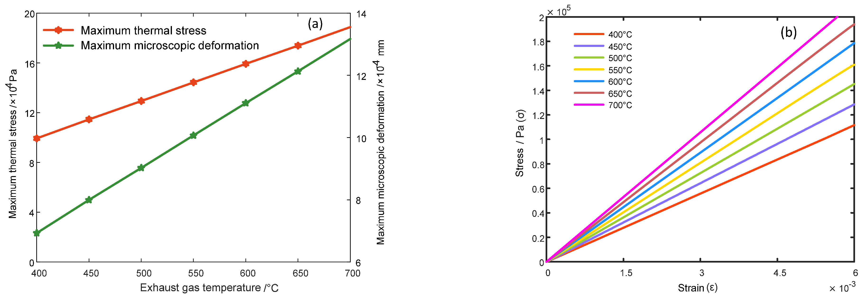
As shown in
Table 3 and
Figure 5a, both the maximum thermal stress and the maximum microscopic deformation in the combustion chamber continuously increase with the rise in exhaust gas temperature; however, the rate of increase of the maximum thermal stress is less than that of the maximum microscopic deformation. When the exhaust gas temperature ranges from 400 °C to 700 °C, the curves in
Figure 5b are fitted, and the fitting results are presented in
Table 4.
It is clearly evident in
Figure 5b and
Table 4 that as the exhaust gas temperature increases, the stress–strain relationship at the location of maximum thermal stress and maximum microscopic deformation in the combustion chamber exhibits a distinct linear relationship. Therefore, throughout the experimental process, the metallic material of the combustion chamber remains within the elastic limit and does not undergo fatigue failure.
Similar to the combustion chamber, the metal gasket is directly subjected to thermal shock during operation. The contour plots of thermal stress and microscopic deformation on the surface of the metal gasket impacted by the high-temperature exhaust gas are shown in
Figure 6. When the exhaust gas temperature ranges from 400 °C to 700 °C, the nodes at the location of thermal stress concentration and maximum microscopic deformation on the metal gasket are at the same position. Therefore, taking this element node as the object of analysis, the relationship between the thermal stress of the metal gasket and the thickness of the gasket is analyzed, as shown in
Figure 7a; the relationship between the microscopic deformation of the metal gasket and the node path is depicted in
Figure 7b.
As indicated in
Figure 7, the thermal stress and microscopic deformation at the node of the metal gasket increase gradually with the rise in exhaust gas temperature. When the exhaust gas temperature is between 400 °C and 450 °C, the heating at the node of the metal gasket is uniform. However, when the exhaust gas temperature exceeds 450 °C, the thermal stress and microscopic deformation at the node increase more rapidly. The maximum thermal stress and maximum microscopic deformation of the metal gasket at different exhaust gas temperatures, as extracted from
Figure 7, are presented in
Table 5 and
Figure 8a, respectively.
A stress–strain relationship diagram at the node at different exhaust gas temperatures is constructed, as shown in
Figure 8b. The curves in
Figure 8b were fitted, and the fitting curves, along with their derivative functions, are presented in
Table 6.
As shown in
Figure 8b, the stress–strain curves at the nodes of the metal gaskets at different exhaust gas temperatures are generally linear. However, the fitting curves are downward-opening parabolas, and the derivative functions have no stationary points within the range of (0, +∞). Therefore, the material of the metal gasket exhibits a tendency to yield but remains within the elastic limit and does not undergo fatigue failure.
Based on the analysis results, it can be concluded that when the exhaust gas temperature ranges from 400 °C to 700 °C, the critical components of the heater will not experience fatigue failure due to thermal stress within the operational temperature range.
3.2. Fatigue Cumulative Damage Life Analysis
Due to the fact that the materials of the heater are composed of high-temperature resistant materials, while considering the impact of thermal stress on the fatigue life of the heater, it is also necessary to analyze the cumulative fatigue life of the key components of the heater at different exhaust gas temperatures caused by thermal shock. Thermal shock refers to a physical phenomenon experienced by a material when it undergoes rapid and non-uniform temperature changes (such as abrupt heating or cooling) over a short period of time. This paper primarily bases its analysis on the thermal shock generated by high-temperature heat flow. Utilizing ABAQUS 6.12 and FE-SAFE 2016, it analyzes the impact of thermal shock from high-temperature heat flow on the combustion chamber and metal gaskets under constant and variable temperature conditions when the exhaust gas temperature ranges from 400 °C to 700 °C.
Based on the output results from
Section 3.1, the analysis results were generated using ABAQUS 6.12 for the temperature ramp that ranges from 400 °C to 700 °C (heating gradient of 50 °C) and the temperature ramp that ranges from 700 °C to 400 °C (cooling gradient of 50 °C). These results were then imported into FE-SAFE 2016 for fatigue life analysis. It was found that the combustion chamber would not experience fatigue damage due to high-temperature thermal–fluidic impact within the operational temperature range. The fatigue damage life results for the metal shims are presented in
Table 7 and
Figure 9.
It is clearly evident in
Table 7 and
Figure 9 that as the exhaust gas temperature increases, the cumulative damage to the metal gasket intensifies, and the fatigue life value gradually decreases. When the exhaust gas temperature is constant at 700 °C and the metal gasket is subjected to high-temperature heat flow impacts for 1,862,171 cycles, fatigue damage occurs. The primary reason is that high-temperature environments significantly reduce the material’s yield strength, ultimate strength, and, critically, its fatigue strength/limit. Under cyclic loading, materials are more susceptible to plastic deformation and fatigue damage at elevated temperatures, resulting in a diminished resistance to fatigue failure. Furthermore, high temperatures may introduce creep effects, which involve slow plastic deformation occurring concurrently with cyclic loading. This phenomenon further accelerates the initiation and propagation rates of fatigue cracks. Collectively, these factors lead to a reduction in the number of cycles to fatigue failure under identical loading conditions, thereby shortening the fatigue life. As observed from the data in the table, cooling operations have little effect on the fatigue life of the metal gasket. This is typically because within the material’s operating temperature range, moderate cooling does not significantly alter its key mechanical properties. For many metallic materials, a decrease in temperature near room temperature may actually increase their yield and ultimate strengths, which can conversely help them resist fatigue damage. When the exhaust gas temperature is between 400 °C and 550 °C, the metal gasket does not experience fatigue failure due to the high-temperature heat flow generated by the heater.
Based on the comprehensive analysis results, it can be concluded that when the exhaust gas temperature ranges from 550 °C to 700 °C, the metal gasket is subject to fatigue failure under high-temperature operation due to the effects of thermal shock. When the exhaust gas temperature is between 400 °C and 700 °C, the cumulative fatigue life of the combustion chamber remains within a reliable range, and thermal shock does not lead to fatigue failure.
4. The Influence of Other Factors on the Fatigue Life of Heaters
Through the analysis of the combustion chamber and the metal gasket, which are two key components of the heater, it can be understood that the static mechanical effects generated by thermal effects do not cause fatigue failure in the heater. Therefore, when considering the fatigue life of the heater, it is sufficient to consider only the cumulative fatigue damage caused by thermal effects.
Based on the analysis described above, it can be deduced that the metal gasket, which is directly subjected to the impact of high-temperature heat flow, not only experiences thermal stress but also thermal shock. Compared to the combustion chamber, the metal gasket is more prone to fatigue damage. Consequently, the quality of the metal gasket is crucial to the normal operation of the heater. In line with the “barrel effect” principle, all analyses in this section focus solely on the metal gasket.
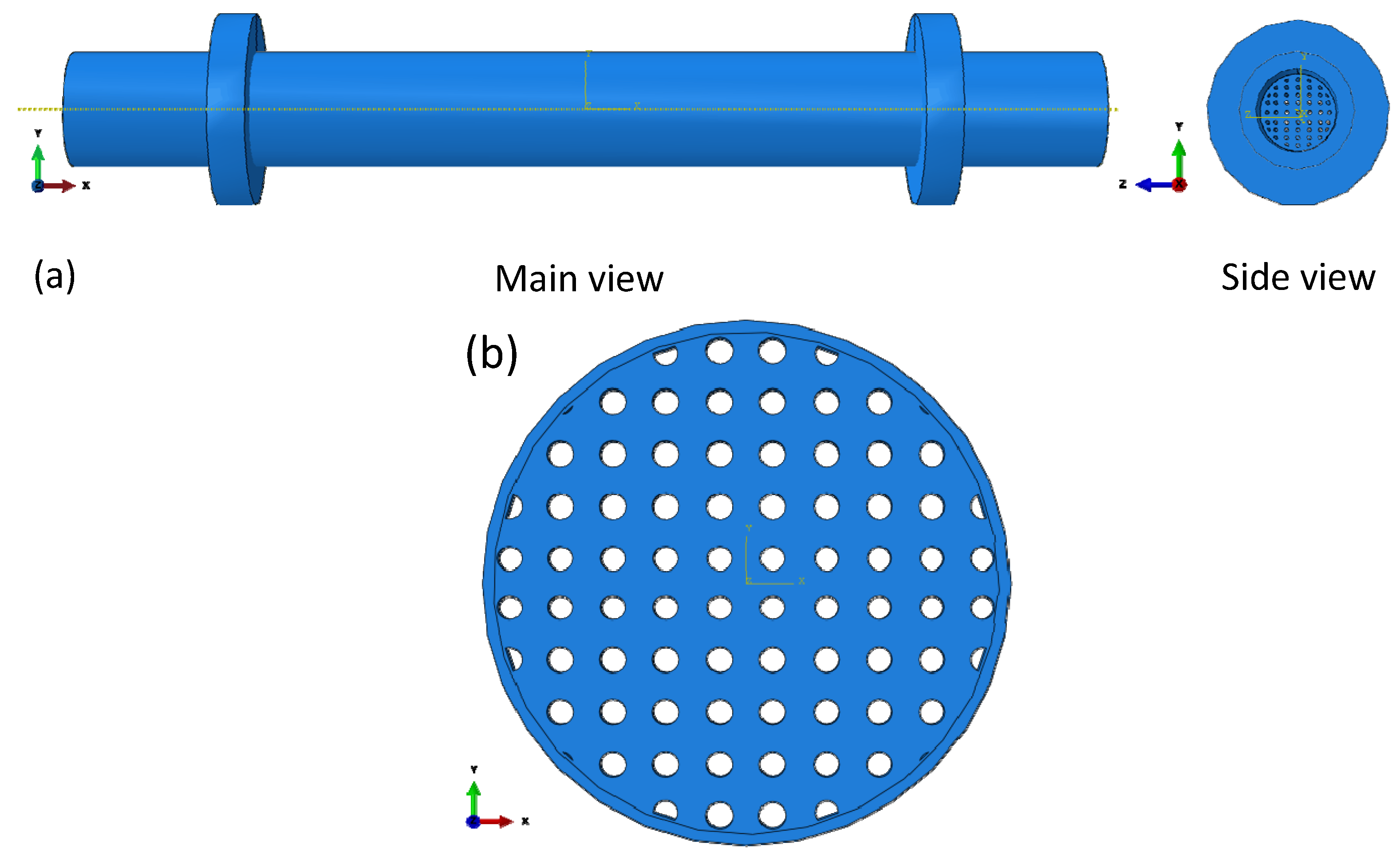
4.1. Metal Gasket Hole Shape
During the operation of the heater, the high-temperature heat flow passes through the pores of the metal gasket and is emitted as high-temperature exhaust gas. The varying shapes of the pores necessarily result in different thermal effects on the metal gasket from the high-temperature exhaust gas. Currently, the experimental process only considers metal gaskets with circular pore shapes, without taking into account gaskets with other shapes. Therefore, a square pore metal gasket design was developed (as shown in
Figure 10 and
Table 8). Utilizing ABAQUS 6.12 in conjunction with FE-SAFE 2016, the steps from
Section 3.2 were repeated to analyze the fatigue life of the square pore metal gasket under constant and variable temperature conditions with exhaust gas temperatures ranging from 400 °C to 700 °C. The results are presented in
Table 9, and a relationship graph between exhaust gas temperature and fatigue life is provided in
Figure 11.
Figure 11 indicates that the fatigue life of the square pore metal gasket decreases with the increase in exhaust gas temperature. The cooling process has almost no effect on the fatigue life of the metal gasket, whereas the heating process significantly reduces it. By comparing
Table 9 and
Figure 9 with
Figure 11, it is evident that the fatigue life of the square pore metal gasket is substantially reduced under the same high-temperature heat flow. Therefore, for practical heater operations, the circular-pore metal gasket is preferred.
4.2. Thickness of the Metal Gasket
As a key component in the operation of a heater, the metal gasket is not only influenced by the shape of its pores but also its thickness, which is one of the primary factors affecting its fatigue life. Both excessively thin and overly thick metal gaskets may lead to rupture due to thermal effects such as high-temperature heat flow impact and heat concentration.
This section, based on experimental grounds, employs ABAQUS 6.12 to design simulation experiments for metal gaskets with thicknesses of 0.5 mm, 1 mm, 2 mm, 3 mm, and 5 mm. The results are analyzed under exhaust gas temperatures ranging from 400 °C to 700 °C under both constant and variable temperature conditions. These results are then imported into FE-SAFE 2016, and the methodology outlined in
Section 3.2 is repeated to calculate the fatigue life. The findings are presented in
Table 10.
Table 10 reveals that the thinner the metal gasket, the shorter its fatigue life becomes with increasing exhaust gas temperature. At an exhaust gas temperature of 700 °C, a 0.5 mm-thick metal gasket fails due to fatigue after being subjected to 448,965 high-temperature heat flow impacts. Conversely, the thicker the metal gasket, the higher its fatigue life value; a 5 mm-thick metal gasket does not experience fatigue failure even after 10
7 high-temperature heat flow impacts at exhaust gas temperatures below 600 °C. Considering only the thickness of the metal gasket, it is most suitable to select a slightly thicker gasket for the experiment.
4.3. Stress Amplitude of the Metal Gasket
During the operation of the heater, due to the influence of experimental conditions, methods, and operations, the high-temperature exhaust gas impacting the metal gasket will exhibit varying speeds and temperatures. Throughout this process, the stress amplitude generated by the thermodynamic effects on the metal gasket is continuously changing. Therefore, taking the exhaust gas temperature of 700 °C as an example, the calculation results from ABAQUS 6.12 are input into FE-SAFE 2016. The stress amplitude is set to 1.2 times, 1.5 times, and 2 times the results of ABAQUS 6.12. By repeating the steps outlined in
Section 3.2, the fatigue life of the metal gasket under different stress amplitude conditions is analyzed, as shown in
Table 11.
It is evident from
Table 11 that the fatigue life of the metal gasket significantly decreases with increasing stress amplitude. When the stress amplitude is doubled from the original operating stress amplitude of the heater, fatigue failure of the metal gasket occurs rapidly.
To validate the simulation results, this study simulated an experiment involving an increased stress amplitude (specifically, simulating twice the stress amplitude) by rapidly heating the exhaust gas temperature to 700 °C through rapid combustion and by abruptly increasing and decreasing the inlet flow velocity to achieve the same temperature. It was observed that under conditions of excessively rapid exhaust gas temperature rise and excessively large inlet flow velocity changes, the metal gasket experienced rapid failure at 125 s into the experiment. The failure location of the retrieved metal gasket was compared with the predicted failure location from the post-processing module of ABAQUS 6.12, with the results shown in
Figure 12.
As can be seen in
Figure 12, when the stress amplitude is twice the original value, the location of the metal gasket failure predicted by the simulation matches that observed in the experimental results. Therefore, the results are validated, confirming that a higher stress amplitude readily leads to the failure of the metal gasket.
5. Conclusions
This paper, based on experimental evidence and combined with finite element simulation, takes the exhaust gas temperature as a variable to analyze the impact of thermal effects on the fatigue life and cumulative fatigue life of key components in the heater, namely, the combustion chamber and the metal gasket. On this basis, the most critical component affecting the heater’s lifespan—the metal gasket—is identified, and the fatigue life of the metal gasket under multifactor conditions is analyzed, providing key evidence for practical operations. According to the research content, the analysis results are as follows:
- (1)
When the exhaust gas temperature ranges from 400 °C to 700 °C, the critical components of the heater will not experience fatigue failure due to thermal stress; metal gaskets do not exhibit fatigue failure within the temperature range of 400 °C to 550 °C; however, fatigue failure begins to occur when the temperature is within the range of 550 °C to 700 °C
- (2)
An increase in exhaust gas temperature leads to aggravated cumulative damage and a reduction in the fatigue life of the metal gasket. At 700 °C, the metal gasket will experience fatigue damage after being subjected to 1,862,171 high-temperature thermal flux impacts. The cooling operation has a negligible impact on the fatigue life of the metal gasket; however, the heating operation significantly reduces its fatigue life.
- (3)
The fatigue life of the metal gasket is influenced by the shape of the holes, the thickness of the gasket, and the stress amplitude. Metal gaskets with square holes exhibit a significant reduction in fatigue life under the same high-temperature thermal flux; the thinner the metal gasket, the lower its fatigue life. An increase in stress amplitude markedly decreases the fatigue life of the metal gasket. Therefore, it is essential to maintain a stable operating environment during the experimental process.
Therefore, based on the conclusions from both experiments and simulations, it is advisable to avoid heating operations with excessive temperature differentials during actual engineering operations. Moreover, the operational process should be conducted under stable experimental conditions, and large variations in stress amplitude should be minimized.


