Article

Structural Response and Failure Analysis of Transmission Towers Under Foundation Sliding with Consideration of Wind Effects

1
Nanxun Innovation Institute, Zhejiang University of Water Resources and Electric Power, Hangzhou 310018, China
2
Energy Engineering Group Zhejiang Power Design Institute Co., Ltd., Hangzhou 310012, China
3
College of Civil Engineering and Architecture, Zhejiang University, Hangzhou 310058, China
*
Author to whom correspondence should be addressed.
Energies 2025, 18(11), 2878; https://doi.org/10.3390/en18112878
Submission received: 24 April 2025 / Revised: 24 May 2025 / Accepted: 29 May 2025 / Published: 30 May 2025

Abstract

To investigate the failure evolution and structural response of transmission towers under the combined effects of foundation sliding and wind loads, this study used the foundation sliding incident of Tower No. 39 on the Xiaoxing transmission line as a case for numerical back-analysis. A transmission tower model was first developed based on the finite element method, and the simulation results were compared with field observations to validate the model, with particular focus on the consistency of typical failure modes such as leg bending and cross-bracing instability. On this basis, the structural response under the combined action of foundation lateral displacement, settlement, and wind loads was further simulated. The results indicate that foundation sliding significantly affects the structural stability of transmission towers, with single-foundation sliding being more destructive than the simultaneous sliding of multiple foundations on the same side. Moreover, the coupling of foundation sliding and wind load substantially reduces the critical displacement required to trigger structural failure. Finally, critical displacement thresholds are proposed, which can serve as reference criteria for damage assessment and engineering intervention when changes in foundation conditions occur.

1. Introduction

In recent years, the collapse of transmission towers due to the combined effects of foundation sliding and wind loads has become an increasingly frequent and critical concern [1,2]. Such foundation deformations can manifest as settlement, displacement, or tilting, ultimately leading to significant structural damage or even the total collapse of towers [3,4]. A notable example occurred in October 2013, when Typhoon Fitow made landfall in Wenzhou, Zhejiang Province. The severe winds and landslides during this event caused extensive damage to the power infrastructure, resulting in the collapse of multiple transmission towers. These incidents highlight the vulnerability of transmission towers under changing foundation conditions and extreme wind loads.
Transmission towers face a dual threat from changes in foundation conditions (such as settlement, tilting, and horizontal displacement) and extreme wind loads. Uneven foundation settlement and horizontal displacement can lead to changes in the force distribution of the transmission tower, causing deformation, damage, and structural failure [5,6]. Furthermore, tower failures directly attributed to extreme wind loads alone are also common and widely documented [7,8,9,10].
Research on the impact of foundation condition changes on transmission towers has been partially explored by scholars. In terms of experimental analysis, Tian et al. [5] studied the effects of foundation deformation on transmission towers and analyzed the response behavior of transmission towers under foundation deformation. Tian et al. [11] also studied the seismic fragility analysis of a transmission tower-line system using shake table tests. Through full-scale tests, Wang [12] studied the failure mechanism of steel tubular transmission towers and concluded that the pole’s eventual collapse resulted from the buckling instability of the compression members in its legs. White [13] treated transmission towers as important surface features and studied the behavior of transmission towers in mining areas affected by foundation movements. Tan [14], Ye [15], and Dou [16] et al. conducted proportional simulation experiments to analyze the changes in the bearing capacity of different tower types under surface deformation effects. Rao et al. [17] experimentally investigated the failure causes of damaged transmission towers and compared the results with relevant regulatory provisions. Shu et al. [18] performed scaled model tests on transmission towers with foundation displacement, revealing that foundation displacement significantly affects the truss members near the support and pointing out the severe adverse effects of wind loads on transmission tower bearing capacity under foundation sliding conditions [19].
In terms of simulation analysis, Ahmed et al. [20] studied the impact of foundation deformation on the safety of transmission towers under bolt slip conditions in steel towers. Yang [21] conducted finite element simulations to analyze the axial force and its variation trends of components under different scenarios (such as foundation settlement, sliding, and tilting), determining the foundation deformation limits of a transmission tower under various conditions. Then, Yang [22] also evaluated the stress state and structural reinforcement methods for transmission towers with foundation settlement. Shu [23,24,25] studied the resistance of transmission towers in mining areas to foundation deformation under different conditions and analyzed the impact of foundation deformation on transmission tower safety. Yang et al. [26] conducted safety analyses of foundation deformation in transmission towers in mining areas under various conditions, revealing the internal force and deformation patterns of critical tower components. Zheng et al. [27] used finite element simulations to study the maximum stress in transmission towers under different conditions and analyzed the deformation patterns of tower legs caused by tilting and landslides. Wang et al. [28] analyzed the stress variation patterns of key members based on the foundation deformation studies under different conditions in landslide areas.
These studies indicate that transmission towers are particularly sensitive to foundation tilting, and efforts should be made to minimize the impact of foundation sliding on the structure. However, most existing studies have focused only on the single impact of foundation displacement and have not thoroughly explored the failure process and safety limits of transmission towers under the combined effects of foundation sliding and wind loads.
The main work of this study includes the following components: (1) We utilized a real-world transmission tower foundation sliding incident as a case study, in which ANSYS 18.0 finite element software and the allowable stress criterion were employed to conduct a numerical back-analysis of the sliding event. The simulation results were then compared with observed field damage to validate the reliability of the finite element model. (2) We carried out a sensitivity analysis of foundation sliding to compare the critical failure displacements between single-foundation sliding and same-side foundation sliding scenarios. (3) We investigated the combined effects of foundation sliding and wind loads on the structural responses of transmission towers and established a critical displacement threshold for tower failure to serve as a reference for damage assessment and engineering intervention.

2. Case Study of Transmission Tower Failure Accident

2.1. Case of Foundation Sliding Accident of Transmission Tower

As shown in Figure 1, Tower No. 39 of the Xiaoxing Line is a typical 220 kV four-circuit angle steel transmission tower. The tower type is SSZV62, with a total height of 56 m, and it adopts a BC2078 slab-type foundation. The SSZV62 tower type refers to a four-circuit angle steel transmission tower on the same pylon. This type of tower is designed to carry four electrical circuits simultaneously. The BC2078 foundation denotes a slab-type foundation with a buried depth of 2 m and a width of 7.8 m. The cross-sectional dimensions of the foundation columns are 1400 × 1400 mm. The tower legs are made of Q345 equal-angle steel and are installed on a layer of silty clay. The standard value of the bearing capacity at the foundation base is 60 kN. In 2011, during construction, a large-scale soil stockpiling operation was carried out on the east side of the tower legs, resulting in inward sliding of the foundations, with a maximum displacement reaching 786 mm.
Following the incident, on-site investigation revealed significant deformation in the tower structure, bending in the tower legs, and instability in both the diagonal and main members of the transverse bracing. Additionally, soil uplift was observed between the No. 3 and No. 4 foundations. These findings indicate a typical failure process characterized by “foundation sliding–member deformation–structural failure”. This incident provides a realistic and reliable validation case for the present study.

2.2. Establishment of the Transmission Tower Model

To reproduce the accident process and conduct parametric analysis, a three-dimensional finite element model of Tower No. 39 on the Xiaoxing Line was developed using the ANSYS finite element software. In the model, the legs and diagonal members of the tower body were modeled using BEAM189 elements, while the conductors and ground wires were simplified as lumped masses and modeled with MASS21 elements to apply mass loading. The primary material used for the tower’s angle steel components was Q345. The elastic modulus of the steel was set to 210 GPa, with a Poisson’s ratio of 0.3 and a density of 7800 kg/m3.
For convenience, the angle steel tower is divided into 12 segments, and the section dimensions of the leg members and diagonal members are shown in Figure 2. The masses of the conductors and ground wires are presented in Table 1. The conductors and ground wires were not detailed in the FEM; instead, they were represented by concentrated masses at the hanging points. Their effects were represented by applying them as concentrated masses and horizontal tensions at their respective hanging points on the tower. Specifically, at the actual connection nodes, a horizontal force (parallel to the conductor’s direction) was applied, and their concentrated mass was incorporated using MASS21 mass elements at these same nodes.
The tower geometry was modeled based on design drawings and field measurements, with a total height of 56 m and a base width of 13.02 m. The foundation was simulated as a rigid fixed support, and sliding behavior was implemented through displacement constraints. The finite element model of the tower is shown in Figure 3. The conductors, represented as concentrated masses, are added to the hanging points in Figure 3.

2.3. Failure Criteria for Structural Members

In this study, the allowable stress criterion specified in the technical code for the technical specification for the design of steel supporting structures of overhead transmission lines (DL/T 5486-2020) [29] was adopted to determine the failure of structural members. A member was considered to have failed when the stress ratio η > 1.0. In the numerical simulations, once the stress ratio of a member exceeded 1.0, it was identified as a failed component.
The failure assessment included the following two types of checks:
(1)
Strength Check
η = N A f y + M x W x f y + M y W y f y 1 γ R
where N denotes axial force; Mx and My are the bending moments about the x and y axes, respectively; A is the cross-sectional area; f y is the yield strength; Wx and Wy are the section moduli about the x and y axes, respectively; and γ R is the partial resistance factor.
(2)
Stability Check
η = N A m N f y φ 1 γ R
where b t b t lim and m N = 1.0 or b t lim < b t 380 f y and m N = 1.667 0.677 b / t b / t lim . For the axial compression member, b t lim = 10 + 0.1 λ 235 f y , while for compression bending members, b t lim = 15 235 f y . b and t are width and thickness of the angle steel member, respectively, and λ is the slenderness. m N is the strength reduction factor. φ is the stability factor accounting for the reduction in bearing capacity due to the instability and is related to the relative slenderness and the section classification, which is constant for the specific member of the tower.

3. Numerical Back-Analysis and Assessment of the Transmission Tower Failure

3.1. Numerical Back-Analysis of the Foundation Sliding Accident

To replicate the failure process of Tower No. 39 on the Xiaoxing Line under the influence of foundation sliding, a numerical back-analysis of the tower was conducted using ANSYS software. Based on field investigation data, the relative sliding displacements of each foundation are listed in Table 2. Foundation No. 2 remained fixed; Foundation No. 1 experienced a −11 mm displacement in the y-direction; Foundation No. 3 slid −700.5 mm in the x-direction; and Foundation No. 4 slid −785.5 mm in the x-direction and −77 mm in the y-direction.
Figure 4 shows the deformation of components near the tower legs under the combined effects of self-weight load and the foundation displacements. Due to the significant inward sliding of Foundations No. 3 and No. 4 along the x-axis, the cross-bracing members aligned in the x-direction experienced severe deformation, and the connected main and diagonal members also deformed significantly.
The failed components resulting from the sliding incident are shown in Figure 5, which are highlighted in blue. As illustrated, the primary members of the cross-bracing in the x-direction, the compressed diagonal members, and the main leg members of the tower all failed.
Figure 6 presents the deformation of the transmission tower observed at the accident site. It can be seen that the inward sliding of Foundations No. 3 and No. 4 caused the bending of the tower leg main members at the intersection with the cross-bracing, as well as the buckling failure of the diagonal and primary cross-bracing members. These observations demonstrate a high degree of consistency between the numerical simulation results and the actual failure observed on-site, indicating the reliability and validity of the numerical back-analysis of this foundation sliding-induced tower failure incident.

3.2. Sensitivity Analysis of Tower Failure Induced by Foundation Sliding

To further investigate the impact of foundation sliding on the structural safety of transmission towers, four foundation sliding scenarios were defined, as shown in Table 3. In scenario GK1, only Foundation No. 4 underwent displacement in the x-direction; in GK2, both Foundations No. 3 and No. 4 experienced displacement in the x-direction; in GK3, only Foundation No. 4 underwent displacement in the y-direction; and in GK4, both Foundations No. 3 and No. 4 experienced displacement in the y-direction.
To account for both the inward and outward sliding of the foundations relative to the tower legs, the displacement range was set from –0.7 m to 0.7 m. When the absolute value of displacement exceeded 0.1 m, the displacement increment was set to 0.1 m; otherwise, an increment of 0.01 m was used. The foundation numbering and displacement directions for scenarios GK1–GK4 are illustrated in Figure 7.
Table 4 summarizes the foundation displacement corresponding to the first typical component failure of the tower. X1 and Y1 represent the displacements in the x- and y-directions at which the first cross-bracing failed, while X2, Y2 correspond to the first main member failure. For single-foundation sliding (GK1, GK3), failures occurred at ±0.04 m (bracing) and ±0.20 m (main members). In same-side dual-foundation sliding (GK2, GK4), similar failure thresholds were observed. However, when foundations No. 3 and 4 slid together, failure occurred at slightly larger displacements. This suggests that single foundation sliding was more likely to induce member failure and thus posed a greater risk compared to the simultaneous sliding of foundations on the same side.
Figure 8 illustrates the failure progress of components in scenario GK1 when Foundation No. 4 slid outward (away from the tower leg) in the x-direction. The failed components are marked in red. As shown in Figure 7a, when the displacement reached +0.04 m, the diagonal bracing at the tower base began to fail. At +0.09 m, the diagonal bracing in the mid-tower cross-bracing started to fail. When the displacement increased to +0.20 m, the main member at the tower base failed. At +0.30 m, the cross-diagonal member in the tower body failed. By the time the displacement reached +0.70 m, all main and diagonal members connected to foundations other than No. 2 had failed.
Figure 9 illustrates the failure progression of components in GK1 when Foundation No. 4 slid inward. The failed members are marked in red. When the displacement reached −0.04 m, the diagonal member of the tower foot cross-bracing began to fail. At −0.09 m of displacement, the diagonal member of the tower body cross-bracing started to fail. When the displacement reached −0.20 m, the main components connected to Foundations No. 1 and No. 4 began to fail. At −0.30 m of displacement, the diagonal members of the tower body started to fail. As the sliding continued, other main components and diagonal members of the tower foot failed sequentially, and the failure propagated to the lower cross-arm of the transmission tower.
Furthermore, Table 5 summarizes the foundation displacement at which the first member failure occurred under different sliding scenarios. The results indicate the following: 1. for single-foundation sliding, failure consistently occurred at a displacement of 0.04 m, regardless of the direction of movement; 2. when both foundations on one side slid inward toward the tower, failure occurred at 0.20 m. When sliding outward, the displacement at failure was 0.20 m in the cross-arm direction and 0.10 m in the line direction.
These findings demonstrate that the structural safety of transmission towers is highly sensitive to foundation sliding. Notably, even small displacements of a single foundation can trigger member failure, underscoring the need for close attention during engineering operation and maintenance.

4. Response Analysis of Transmission Towers Under Combined Effects of Wind Loads and Foundation Sliding

4.1. Transmission Tower Model and Case Setup

4.1.1. Transmission Tower Model

To investigate the impact of foundation sliding on the structural safety performance of transmission towers under wind loads, this section focuses on Tower No. 39 of the Xiaoxing Line as a case study, conducting a structural response analysis considering the combined effects of foundation sliding and wind loads. The finite element model used in this section was consistent with that described in Section 3. The tower type was SSZV62, with a design wind speed of 36 m/s.

4.1.2. Case Setup

As shown in Table 6, a total of seven displacement cases were defined, covering both the horizontal sliding and vertical settlement of the foundation. The specific displacement directions for each case are illustrated in Figure 10. In cases JX1, JY1, and JZ1, Foundation No. 4 underwent displacement in the x-, y-, and z-directions, respectively. In case JX2, Foundations No. 3 and No. 4 were simultaneously displaced in the x-direction; in JY2, Foundations No. 1 and No. 4 were simultaneously displaced in the y-direction; in JZ2, Foundations No. 3 and No. 4 settled in the z-direction; and in JZ3, Foundations No. 1 and No. 4 settled in the z-direction. The displacement range for horizontal sliding (x- and y-directions) was set from –0.3 m to +0.3 m, and for vertical settlement (z-direction), it was from 0 to 0.2 m.
Meanwhile, this section also evaluates the safety performance of transmission towers with foundation sliding under regular wind conditions (LD1) and extreme wind conditions (LD2). The load cases are summarized in Table 7. For Tower No. 39, the regular wind speed was 11 m/s, and the design wind speed was 36 m/s.

4.1.3. Computational Procedure

This section details how we carried out finite element simulations for seven displacement cases under the combined action of two wind load cases. The computational procedure is illustrated in Figure 11.
First, a finite element model of the transmission tower was established in ANSYS. The wind load cases and foundation displacement scenarios were defined. An initial static analysis was performed to obtain the internal forces of the structural members. Based on the internal forces, each member was classified as either a compression or tension member. For compression members, the critical buckling stress (refer to Formula 3) was assigned as the yield strength in the material parameters. For tension members, the material model remained unchanged.
F cr = π 2 E I 0.5 L 2 1
where F cr is the critical buckling load; E is the Young modulus of the material; I is the area moment of inertia of the member’s cross-section about the axis of buckling; and L is the length of the member.
Next, the material constitutive models in the finite element model were updated accordingly, and a second analysis was conducted to evaluate the structural response under the combined effects of wind load and foundation displacement. Based on the structural failure criteria, it was determined whether the structure had failed. If no failure occurred, the magnitude of foundation displacement was incrementally adjusted, and the static analysis was repeated from the beginning. This iterative process continued until the failure displacement was obtained for each load and displacement scenario.
Structural failure was determined according to the following criteria: 1. the maximum horizontal displacement angle at the tower top exceeded 1/75 of the tower height; 2. the stress ratio of the main structural member exceeded 1.0.

4.2. Tower Top Displacement Angle

Figure 12 and Figure 13 illustrate the variation in the tower top displacement angle under the combined effect of wind loads (LD1, LD2) and foundation displacement. It can be observed that an increase in wind speed led to a larger tower top displacement angle. Among the cases analyzed, the sliding of Foundations No. 3 and No. 4 in the x-direction (JX2) resulted in the most significant impact on the tower top displacement. As the displacement increased, the influence of wind speed on Case JY2 (the sliding of Foundations No. 1 and No. 4 in the y-direction) gradually diminished.
When the foundation underwent horizontal displacement, the resulting tower top displacement angle remained minimal and did not approach the ultimate failure limit of 1/75 for transmission towers. For outward sliding, where the foundation displacement direction was consistent with the wind direction, the tower top displacement angle increased significantly in the case of LD2-JX2, while changes were less pronounced for the case of LD2-JY2. For inward sliding, where the foundation displacement direction was opposite to the wind direction, the displacement angle under high-wind-speed conditions (LD2-JX2) tended to initially decrease and then increase. In particular, under high wind speed, Case LD2-JY2 (Foundations No. 1 and No. 4 sliding in the y-direction) resulted in a significant increase in the tower top displacement angle.
In the case of foundation settlement, under various loading conditions, the tower top displacement exceeded the permissible limit and reached the collapse threshold when Foundations No. 3 and No. 4 settled to 0.16 m (JZ2) and when Foundations No. 1 and No. 4 settled to 0.17 m (JZ3).

4.3. Member Failure Analysis

4.3.1. Lateral Displacement-Induced Failure Process of Transmission Tower Members

Figure 14 illustrates the progression of member failures in the transmission tower when the No. 4 foundation underwent lateral displacement in the x-direction under extreme wind load. Members marked in red represent those with a stress ratio exceeding 1.0, indicating failure. These failed components were predominantly concentrated in the lower portion of the tower on the sliding side, particularly around the corner joints of the tower legs.
To assess structural safety, two displacement thresholds are defined:
  • Critical failure displacement: the foundation displacement at which the first tower member fails.
  • Critical collapse displacement: the foundation displacement at which the main leg member connected to the foundation fails, indicating potential tower collapse.
When the No. 4 foundation shifted outward (away from the tower leg) and reached a critical failure displacement of 0.02 m, the cross-bracing member above the No. 2 foundation failed first. At a critical collapse displacement of 0.12 m, the main leg member connected to the No. 1 foundation failed. When the foundation shifted inward, the cross-bracing above the No. 1 foundation failed at 0.02 m, and the main leg member connected to the No. 4 foundation failed at 0.07 m.
In condition JX1-LD2, the evolution of member failures under increasing foundation displacement was as follows: at 0.02 m of displacement, failure initiated in the horizontal bracing members; and as displacement increased to 0.07–0.12 m, the diagonal and main leg members sequentially failed. The overall failure path followed the following pattern: “Initial buckling of horizontal bracing → Instability of diagonal members → Failure of main members”.
Figure 15 illustrates the progressive failure of structural members in the tower under extreme wind conditions when Foundations No. 3 and No. 4 underwent lateral displacement in the x-direction. Under these circumstances, the critical failure displacement and the critical collapse displacement for Foundations No. 3 and No. 4 were coincidental. Upon the outward sliding of the foundations (away from the tower leg) by 0.10 m, the initial structural member to fail was the main leg connected to Foundation No. 1. Conversely, with the inward sliding of the foundations (towards the tower leg) by 0.09 m, the first structural member to fail was the main leg connected to Foundation No. 4.
Table 8 summarizes the failure conditions of the transmission tower under foundation lateral displacement combined with wind loads. It can be seen that displacement of a single foundation was more likely to cause member failure, while the direction of foundation displacement had a relatively minor effect on the critical displacement.

4.3.2. Settlement-Induced Failure Process of Transmission Tower Members

Figure 16, Figure 17 and Figure 18 illustrate the failed members of the transmission tower under extreme wind conditions for three foundation settlement cases. In Case JZ1-LD2, when Foundation 4# settled to the critical failure displacement of 0.01 m, damage first occurred in the bracing plane members at the tower base. When the settlement reached the critical collapse displacement of 0.05 m, the main structural member connected to Foundation 3# at the tower base failed. In Case JZ2-LD2, when both Foundations 3# and 4# settled simultaneously to 0.12 m, the main member at the tower base connected to Foundation 4# was the first to fail. In Case JZ3-LD2, when Foundations 1# and 4# settled simultaneously to 0.12 m, the main structural members at the tower base connected to Foundations 3# and 4# failed first.

5. Discussion

This study investigated the structural responses of a transmission tower under the combined effect of two wind load cases and seven foundation displacement scenarios. A systematic analysis was conducted to assess the influence of foundation sliding on the structural response and member failure paths. Based on the results, the following conclusions are drawn:
(1)
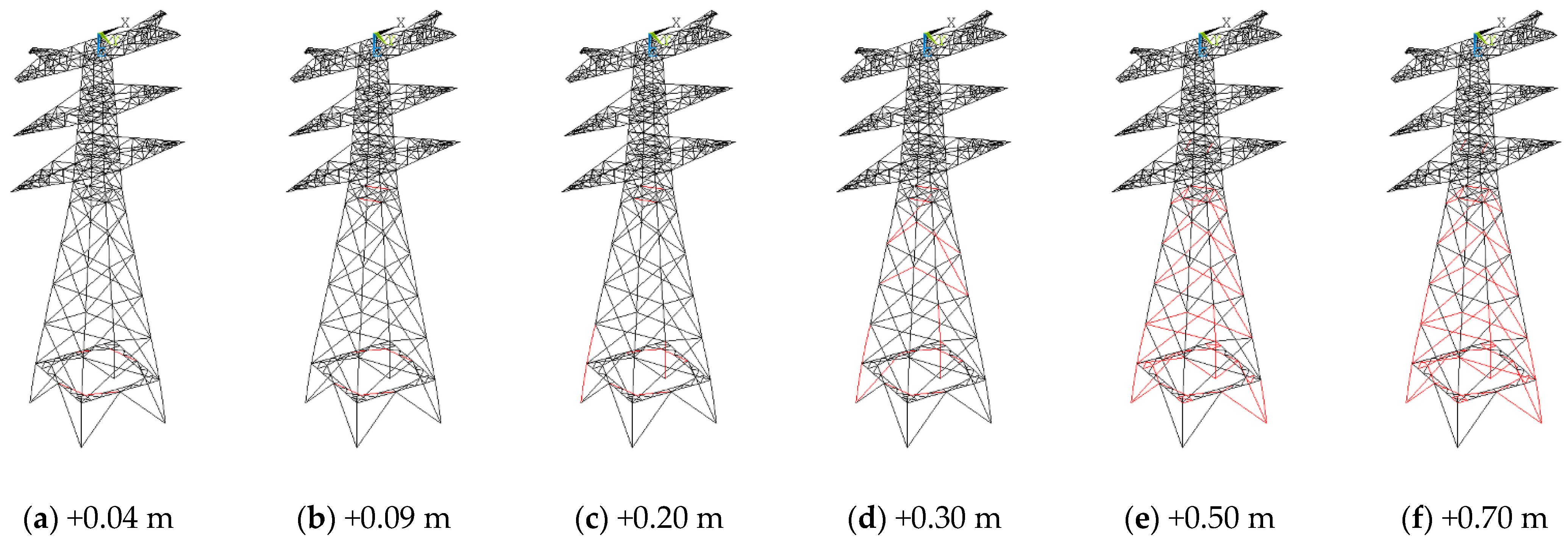
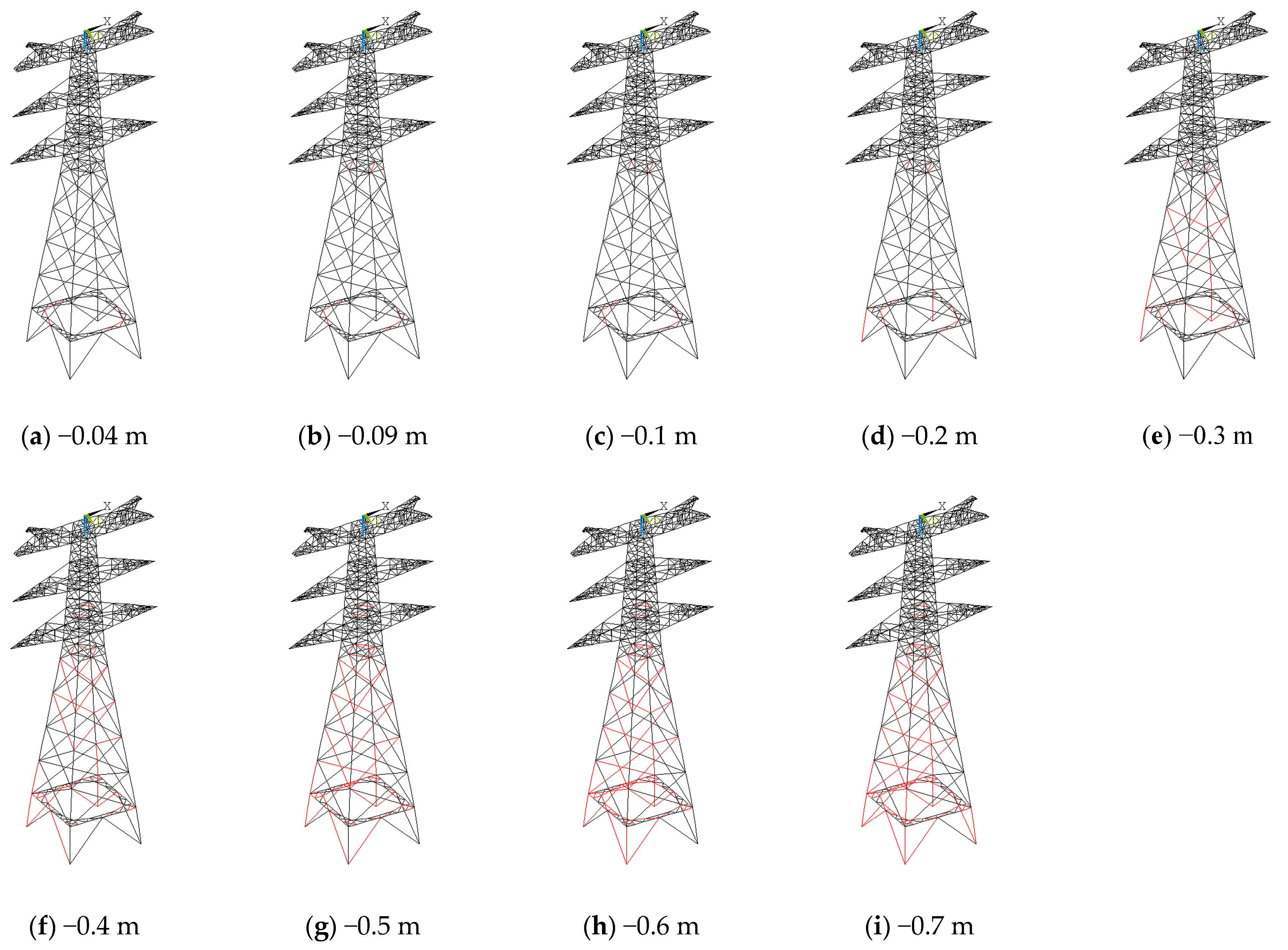
Failure path evolution was concentrated in the bottom part of the tower on the sliding side.
The simulation results show that, regardless of the displacement scenario, member failure consistently initiated at the junction between the bracing plane and the tower leg on the sliding side. It then progressively propagated to adjacent diagonal and main members, forming a failure chain characterized by a “bottom-to-top, local-to-global” evolution pattern.
(2)
Single-foundation sliding poses greater risk than same-side simultaneous sliding.
Consistent with the accident back-analysis presented in Section 3, the results in Section 4 further confirm that, under the same displacement magnitude, single-foundation sliding triggered member failure at a smaller critical displacement and induced a more severe structural response compared to simultaneous sliding of foundations on the same side.
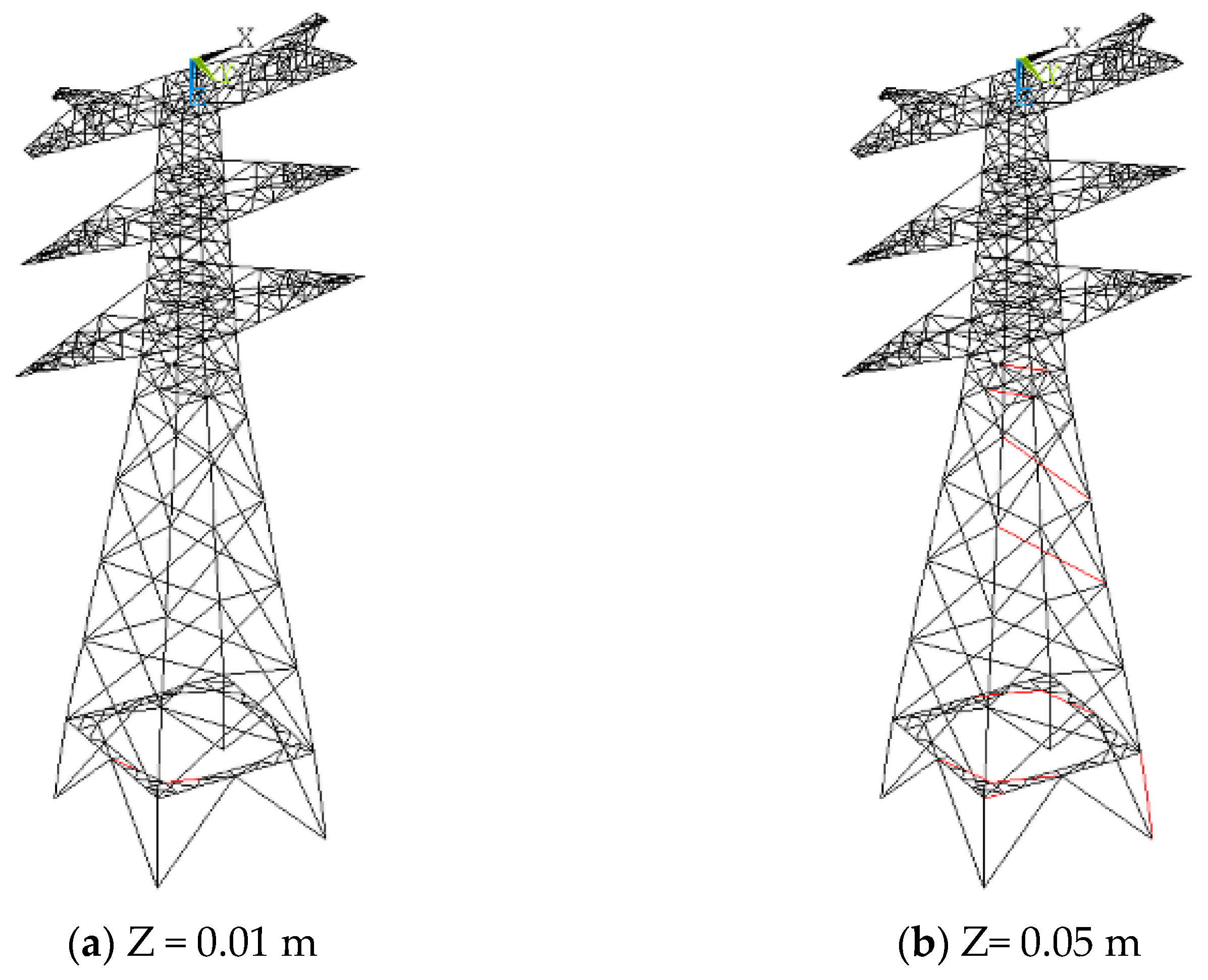
For example, under scenario JX1-LD2, the first bracing member of the transmission tower failed at a sliding displacement of 0.07 m, whereas under scenario JX2-LD2, failure was delayed until the foundation displacement reached 0.09 m.
This was primarily due to the severe asymmetric deformation caused by single-foundation sliding, which leads to localized overstressing and earlier buckling failure in components. Therefore, even minor single-foundation displacements warrant heightened engineering attention and preventive measures.
(3)
The combined effect of wind loads and foundation sliding significantly amplifies structural risk.
The interaction between foundation sliding and wind loads exhibited a synergistic amplification effect, whereby the critical failure displacement under extreme-wind-load conditions was reduced by 10% to 30% compared to normal-wind-load conditions. Furthermore, the relative orientation between the sliding foundation and the wind direction influenced the failure path, with the most unfavorable scenario occurring when the foundation slid inward and aligns with the direction of wind.
(4)
Safety warning thresholds for foundation sliding are proposed.
The critical collapse displacement of a transmission tower is primarily governed by the failure of its main structural members. Thus, using tower collapse as the criterion, the foundation displacement corresponding to the failure of main members is defined as the critical threshold for safety warning, as shown in Table 9.
If the measured foundation lateral displacement or settlement exceeds the threshold values, and abnormal deformations are observed in the bracing members, an evaluation process should be initiated to determine whether the structural reinforcement or replacement of the transmission tower is necessary.

6. Conclusions

Based on the accident back-analysis of Tower No. 39 on the Xiaoxing Line, a finite element model was developed to conduct a sliding sensitivity analysis and to calculate the displacement response and failure path of the transmission tower under the combined effects of wind load and foundation sliding. The following conclusions are drawn:
(1)
The numerical back-analysis results of the foundation sliding incident were consistent with the observed consequences of the Tower No. 39 failure on the Xiaoxing Line, thereby validating the effectiveness of the finite element simulation.
(2)
Foundation sliding has a significant impact on the structural safety of transmission towers, with single-foundation sliding posing a greater risk than same-side multi-foundation sliding.
(3)
Upon the failure of transmission towers, the sequence of structure failure typically initiates with the horizontal bracing members in the first bay, followed by the tower legs. In regions with a high incidence of landslides, maintenance personnel should prioritize enhanced observation and monitoring of these critical structural members.
(4)
The collapse of transmission towers is primarily attributed to the main leg members reaching their ultimate stress capacity, even when the tower top displacement angle remains within permissible limits. During operation and maintenance, stress monitoring of the main members should be prioritized, with the monitoring of the tower top displacement serving as a supplementary measure.
(5)
The combined effect of wind loads and foundation sliding significantly amplifies structural risk. The critical failure displacement under extreme-wind-load conditions is reduced by 10% to 30% compared to normal-wind-load conditions.

Author Contributions

Conceptualization, W.Q. and J.Y.; methodology, W.Q. and Z.T.; investigation, W.Q. and Z.T.; writing—original draft preparation, W.Q.; writing—review and editing, Z.L., Y.G., G.S., and J.Y. All authors have read and agreed to the published version of the manuscript.

Funding

This research was funded by Zhejiang Provincial Natural Science Foundation of China (No. LTGS23E080003). The authors also appreciate the strong support of the Nanxun Scholars Program for Young Scholars of ZJWEU under Grant RC2023021201. The opinions and statements do not necessarily represent those of the sponsors.

Institutional Review Board Statement

Not applicable.

Data Availability Statement

Data are contained within this article.

Conflicts of Interest

Author Jianfeng Yao and Yong Guo were employed by the company Energy Engineering GroupZhejiang Power Design Institute Co., Ltd. The remaining authors declare that the research was conducted in the absence of any commercial or financial relationships that could be construed as a potential conflict of interest.

References

  1. Liu, S.; Yin, K.; Zhou, C.; Gui, L.; Liang, X.; Lin, W.; Zhao, B. Susceptibility Assessment for Landslide Initiated along Power Transmission Lines. Remote Sens. 2021, 13, 5068. [Google Scholar] [CrossRef]
  2. Huang, C.; Yin, K.; Liang, X.; Gui, L.; Zhao, B.; Liu, Y. Study of direct and indirect risk assessment of landslide impacts on ultrahigh-voltage electricity transmission lines. Sci. Rep. 2024, 14, 25719. [Google Scholar] [CrossRef] [PubMed]
  3. Deng, C.; Cao, Y.; Xue, Z.; Bo, X.; Li, W.; Shi, Y. A case study of landslide monitoring system for a transmission tower in Maoxian, Sichuan China. In Proceedings of the 2017 IEEE 9th International Conference on Communication Software and Networks (ICCSN), Guangzhou, China, 6–8 May 2017; IEEE: New York, NY, USA, 2017; pp. 1516–1519. [Google Scholar] [CrossRef]
  4. Liang, X.; Segoni, S.; Yin, K.; Du, J.; Chai, B.; Tofani, V.; Casagli, N. Characteristics of landslides and debris flows triggered by extreme rainfall in Daoshi Town during the 2019 Typhoon Lekima, Zhejiang Province, China. Landslides 2022, 19, 1735–1749. [Google Scholar] [CrossRef]
  5. Tian, L.; Gai, X.; Qu, B.; Li, H.; Zhang, P. Influence of Spatial Variation of Ground Motions on Dynamic Responses of Supporting Towers of Overhead Electricity Transmission Systems: An Experimental Study. Eng. Struct. 2016, 128, 67–81. [Google Scholar] [CrossRef]
  6. Long, X.; Wang, W.; Fan, J. Collapse Analysis of Transmission Tower Subjected to Earthquake Ground Motion. Model. Simul. Eng. 2018, 2018, 2687561. [Google Scholar] [CrossRef]
  7. Meng, X.; Tian, L.; Liu, J.; Jin, Q. Failure prediction of overhead transmission lines incorporating time series prediction model for wind-ice loads. Reliab. Eng. Syst. Saf. 2025, 259, 110927. [Google Scholar] [CrossRef]
  8. Wang, T.; Dong, Y.; Wang, L.; Lu, D.; Hu, S.; Tan, Y.; Li, Z. Global reliability assessment of coupled transmission tower-insulator-line systems considering soil-structure interaction subjected to multi-hazard of wind and ice. J. Constr. Steel Res. 2024, 223, 109004. [Google Scholar] [CrossRef]
  9. Ma, L.; Khazaali, M.; Bocchini, P. Component-Based Fragility Analysis of Transmission Towers Subjected to Hurricane Wind Load. Eng. Struct. 2021, 242, 112586. [Google Scholar] [CrossRef]
  10. Liang, Y.; Zhao, C.-X.; Wei, Y.-Y.; Tong, M.-N.; Feng, H.-Q.; Dong, X.-S. Fragility analysis of an ultra high voltage transmission tower in saline soil subjected to wind loads. Struct. Infrastruct. Eng. 2023, 21, 845–862. [Google Scholar] [CrossRef]
  11. Tian, L.; Yang, M.; Liu, J.; Ma, Z.; Gong, J.; Chen, H.; Luo, X. Shake table test and seismic fragility analysis of transmission tower-line system considering duration effect. Thin-Walled Struct. 2024, 197, 111584. [Google Scholar] [CrossRef]
  12. Wang, J.; Qi, H.; Zhang, Z.; Zhang, B.; Sun, Q. Failure mechanism of a Q690 steel tubular transmission Tower: Full-Scale experiment and numerical simulation. Eng. Struct. 2023, 295, 116881. [Google Scholar] [CrossRef]
  13. White, B.H. Outcomes of the Independent Inquiry into Impacts of Underground Coal Mining on Natural Features in the Southern Coalfield-an Overview. In Proceedings of the 2009 Coal Operators Conference, University of Uollongong, Wollongong, NSW, Australia, 12–13 February 2009; pp. 112–123. [Google Scholar]
  14. Tan, X.Z. Study on the Anti-Surface Deformation Performance of Composite Foundation with Opening of Transmission Tower. Master’s Thesis, China University of Mining and Technology, Xuzhou, China, 2015. (In Chinese). [Google Scholar]
  15. Ye, S. Study on Ground Deformation and Wind Resistant Performance of 110 kV Transmission Tower in Mining Subsidence Area. Master’s Thesis, China University of Mining and Technology, Xuzhou, China, 2015. (In Chinese). [Google Scholar]
  16. Dou, T. Study on the Load of the Preset Lifting Lower Foot and Foundation of Power Transmission Tower in Mining Area. Master’s Thesis, China University of Mining and Technology, Xuzhou, China, 2016. (In Chinese). [Google Scholar]
  17. Rao, N.P.; Knight, G.S.; Mohan, S.J.; Lakshmanan, N. Studies on Failure of Transmission Line Towers in Testing. Eng. Struct. 2012, 35, 55–70. [Google Scholar] [CrossRef]
  18. Shu, Q.; Yuan, G.; Huang, Z.; Ye, S. The Behaviour of the Power Transmission Tower Subjected to Horizontal Support’s Movements. Eng. Struct. 2016, 123, 166–180. [Google Scholar] [CrossRef]
  19. Shu, Q.; Huang, Z.; Yuan, G.; Ma, W.; Ye, S.; Zhou, J. Impact of Wind Loads on the Resistance Capacity of the Transmission Tower Subjected to Ground Surface Deformations. Thin-Walled Struct. 2018, 131, 619–630. [Google Scholar] [CrossRef]
  20. Ahmed, K.; Rajapakse, R.; Gadala, M. Influence of Bolted-Joint Slippage on the Response of Transmission Towers Subjected to Frost-Heave. Adv. Struct. Eng. 2009, 12, 1–17. [Google Scholar] [CrossRef]
  21. Yang, F.; Yang, J.; Han, J.; Zhang, Z. Study on the Limited Values of Foundation Deformation for a Typical UHV Transmission Tower. IEEE Trans. Power Deliv. 2010, 25, 2752–2758. [Google Scholar] [CrossRef]
  22. Yang, F.; Li, Q.; Yang, J.; Zhu, B. Assessment on the Stress State and the Maintenance Schemes of the Transmission Tower above Goaf of Coal Mine. Eng. Fail. Anal. 2013, 31, 236–247. [Google Scholar] [CrossRef]
  23. Shu, Q.; Yuan, G.; Guo, G.; Zhang, Y. Limits to Foundation Displacement of an Extra High Voltage Transmission Tower in a Mining Subsidence Area. Int. J. Min. Sci. Technol. 2012, 22, 13–18. [Google Scholar] [CrossRef]
  24. Shu, Q.; Yuan, G.; Zhang, Y.; Guo, G. Research on Anti-Foundation-Displacement Performance and Reliability Assessment of 500 KV Transmission Tower in Mining Subsidence Area. Open Civ. Eng. J. 2011, 5, 87. [Google Scholar] [CrossRef]
  25. Shu, Q.J.; Yuan, G.L.; Zhang, Y.F.; Guo, G.L. Research on Performance of Resisting Foundation Displacement of High Voltage Electricity Transmission Tower in Mining Subsidence Area. Adv. Mater. Res. 2011, 168, 2308–2314. [Google Scholar] [CrossRef]
  26. Yang, G.; Wang, T.Z.; Wang, D.W. The influence of tower deformation process on the safety of transmission towers in the mining subsidence area. Sci. Technol. Eng. 2019, 19, 206–212. (In Chinese) [Google Scholar]
  27. Zheng, W.L.; Zhang, F.C.; Wang, Y.H. Safety Analysis and Evaluation of Transmission Towers in Landslide Areas. Power Syst. Clean Energy 2019, 9, 25–33. (In Chinese) [Google Scholar]
  28. Wang, Y.H.; Liu, X.L.; Ren, W.Q. Anti-deformation ability and dynamic response analysis of transmission tower-line system in landslide area. Sci. Technol. Eng. 2021, 21, 10725–10731. (In Chinese) [Google Scholar]
  29. DL/T 5486-2020; Technical Specification for the Design of Steel Supporting Structures of Overhead Transmission Line. China Planning Press: Beijing, China, 2021.
Figure 1. Tower No. 39 of the Xiaoxing Line.
Energies 18 02878 g001
Figure 2. Configuration of transmission tower.
Energies 18 02878 g002
Figure 3. The finite element model of the tower.
Energies 18 02878 g003
Figure 4. The deformation of components near the tower legs under the combined effects of self-weight and the foundation displacements.
Energies 18 02878 g004
Figure 5. The failed components resulting from the sliding incident. (The arrows represent the displacement direction of the foundation.)
Energies 18 02878 g005
Figure 6. The deformation of the transmission tower observed at the accident site.
Energies 18 02878 g006
Figure 7. The foundation numbering and displacement directions for scenarios GK1–GK4. (The arrows represent the displacement direction of the foundation.)
Energies 18 02878 g007
Figure 8. The failure progress of components in scenario GK1 when Foundation No. 4 slid outward.
Energies 18 02878 g008
Figure 9. The failure progress of components in scenario GK1 when Foundation No. 4 slid inward.
Energies 18 02878 g009
Figure 10. The displacement directions for the sliding cases of the foundation. (The arrows represent the displacement direction of the foundation.)
Energies 18 02878 g010
Figure 11. The computational procedure of the finite element simulation.
Energies 18 02878 g011
Figure 12. Tower top displacement angle under foundation lateral displacement.
Energies 18 02878 g012
Figure 13. Tower top displacement angle under foundation settlement.
Energies 18 02878 g013
Figure 14. The progression of member failures in the transmission tower in Case JX1-LD2.
Energies 18 02878 g014
Figure 15. The progression of member failures in the transmission tower in Case JX2-LD2. (a) the foundation slides outward by 0.1 m. (b) the foundation slides inward by 0.09 m.
Energies 18 02878 g015
Figure 16. Case JZ1-LD2.
Energies 18 02878 g016
Figure 17. Case JZ2-LD2.
Energies 18 02878 g017
Figure 18. Case JZ3-LD2.
Energies 18 02878 g018
Table 1. The masses of the conductors and ground wires.
Conductor SystemMass/kGType
ground wires1800LGJ-95/55
upper conductor70162×LGJ-630/45
middle conductor65592×LGJ-630/45
lower conductor59962×LGJ-630/45
Table 2. The relative displacements of each foundation.
Foundationx-Direction/mmy-Direction/mm
1#0−11
2#00
3#−700.50
4#−785.5−77
Table 3. The foundation sliding scenarios.
ScenarioFoundationX/mY/m∆/m
GK14#−0.7~0.7--0.1 (0.01)
GK23#, 4#−0.7~0.7--0.1 (0.01)
GK34#--−0.7~0.70.1 (0.01)
GK43#, 4#--−0.7~0.70.1 (0.01)
Table 4. The foundation displacement corresponding to the first typical component failure of the tower.
ScenarioFoundationX1/mX2/mY1/mY2/m
GK14#−0.04, +0.04−0.20, +0.20----
GK23#, 4#−0.30, +0.20−0.20, +0.20----
GK34#----−0.04, +0.04−0.20, +0.20
GK41#, 4#----−0.20, +0.10−0.20, +0.20
Table 5. Foundation displacement at member failure under different scenarios.
DirectionInwardOutward
Foundation Displacement
Scenario
GK1 −0.04 m+0.04 m
GK2 −0.20 m+0.20 m
GK3 −0.04 m+0.04 m
GK4 −0.20 m+0.10 m
Table 6. The horizontal sliding and vertical settlement cases of the foundation.
CaseFoundationX (m)Y (m)Z (m)
JX14#−0.3~0.3----
JX23#, 4#−0.3~0.3----
JY14#--−0.3~0.3--
JY21#, 4#--−0.3~0.3--
JZ14#----0~0.2
JZ23#, 4#----0~0.2
JZ31#, 4#----0~0.2
Table 7. Load case configuration.
Load CaseLoad CombinationsWind Speed (m/s)
LD1Dead Load + Normal Wind Load11
LD2Dead Load + Extreme Wind Load36
Table 8. The failure conditions of the tower under foundation lateral displacement.
CaseCritical Failure Displacement (m)Critical Collapse Displacement (m)
JX1-LD10.04 (outward)/0.04 (inward)0.12 (outward)/0.11 (inward)
JX2-LD10.13 (outward)/0.13 (inward)0.13 (outward)/0.13 (inward)
JY1-LD10.04 (outward)/0.04 (inward)0.12 (outward)/0.10 (inward)
JY2-LD10.10 (outward)/0.13 (inward)0.13 (outward)/0.13 (inward)
JX1-LD20.02 (outward)/0.02 (inward)0.12 (outward)/0.07 (inward)
JX2-LD20.10 (outward)/0.09 (inward)0.10 (outward)/0.09 (inward)
JY1-LD20.02 (outward)/0.02 (inward)0.08 (outward)/0.07 (inward)
JY2-LD20.08 (outward)/0.09 (inward)0.08 (outward)/0.09 (inward)
Table 9. The critical displacement thresholds for foundation sliding.
CaseCritical Foundation Displacement (m)
JX10.12 (outward)/0.07 (inward)
JX20.10 (outward)/0.09 (inward)
JY10.08 (outward)/0.07 (inward)
JY20.08 (outward)/0.09 (inward)
JZ10.05
JZ20.12
JZ30.12
Disclaimer/Publisher’s Note: The statements, opinions and data contained in all publications are solely those of the individual author(s) and contributor(s) and not of MDPI and/or the editor(s). MDPI and/or the editor(s) disclaim responsibility for any injury to people or property resulting from any ideas, methods, instructions or products referred to in the content.

