Abstract
Cable-suspended photovoltaic (PV) systems have gained traction due to their lightweight structure and adaptability to complex terrains. However, the wind-induced vibration behavior of these systems, particularly the contribution of glass–glass PV modules to structural stiffness, remains inadequately addressed in current design codes. This study presents a comprehensive finite element analysis to investigate the mechanical role of glass–glass PV modules in cable-suspended PV systems. A high-fidelity model (HFM) capturing detailed structural features of the PV module is established and used as a reference to develop an equivalent stiffness model (ESM). Through modal decomposition under wind excitation, it is shown that module deformation primarily manifests as torsion, which significantly contributes to the overall stiffness of the support structure. Comparative simulations reveal that conventional modeling approaches, including the inaccurate simplified model (ISM), overestimate stiffness, potentially compromising structural safety. The ESM, by accurately replicating the HFM’s torsional response, enables efficient and reliable wind-induced vibration analysis. The results also indicate that modules at the cable span edges experience greater torsional deformation, especially under suction forces, highlighting a critical zone for structural reinforcement.
1. Introduction
Driven by the global transition in the energy structure and the pursuit of sustainable development, photovoltaic (PV) technology—an essential pillar of clean energy—is undergoing unprecedented growth. According to statistics from the International Renewable Energy Agency (IRENA), the newly installed PV capacity worldwide reached 452 GW in 2024, with the total cumulative capacity surpassing 1.85 TW. Of this, China contributed over 0.9 TW, accounting for 48.5% of the global total, and led the world with an annual addition of 280 GW [1]. This explosive growth is not only transforming the traditional energy supply landscape but also promoting continuous technological innovation in the PV sector. Amidst this evolution, glass–glass PV modules have emerged as a mainstream choice due to their outstanding mechanical strength and weather resistance. Simultaneously, cable-suspended PV systems have seen widespread application in large-scale solar farms owing to their lightweight design and adaptability to complex terrains. As shown in Figure 1, the combined use of glass–glass PV modules and cable-suspended PV systems has demonstrated considerable effectiveness in engineering practice.
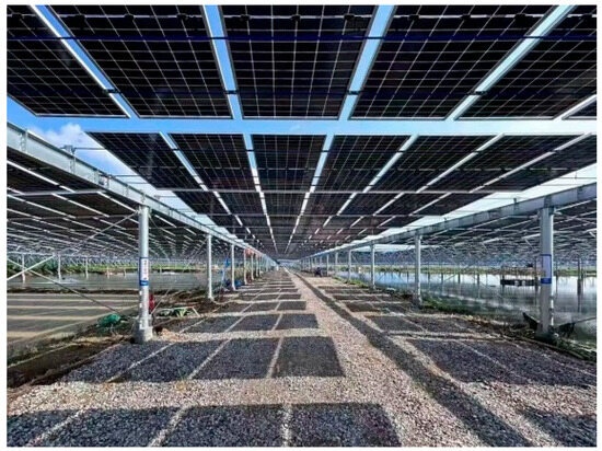
Figure 1.
Cable-suspended PV systems and glass–glass PV modules.
However, as extreme weather events become more frequent, the wind resistance performance of PV systems faces new challenges. Current design standards lack clear provisions for wind-induced vibrations in cable-suspended PV systems and PV modules. At present, international design standards for the wind resistance of photovoltaic (PV) systems predominantly focus on fixed PV systems and tracking PV systems, with limited consideration given to cable-suspended PV systems and their associated wind-induced vibration issues. Although the International Electrotechnical Commission (IEC) has established standards addressing the strength and system wind resistance of PV modules, these standards are confined to building-integrated PV (BIPV), fixed PV systems, and tracking PV systems [2,3,4]. The American standard ASCE 7-22, while being the first to include a dedicated chapter on wind loads for PV systems, is still largely based on research conducted on fixed PV systems, rendering it less applicable to cable-suspended PV systems [5]. Several standards in China addressing PV systems consider fixed PV systems and cable-suspended PV systems, but they only provide recommended wind load values and lack sufficient consideration of wind-induced vibrations in cable-suspended PV systems [6,7]. This highlights a pronounced lag in industry standards, which often compels engineers to rely on wind tunnel testing for accurate design parameters or to adopt conservative strategies based on precedent projects. The absence of systematic guidance not only increases design and construction costs but also carries the risk of underestimating potential structural vulnerabilities.
Outside the scope of existing standards, a limited number of studies have investigated cable-suspended PV systems, primarily focusing on wind load distribution and wind-induced vibration. Li et al. [8] carried out wind tunnel tests to study the effects of wind load on cable-suspended PV arrays with different lengths and widths, and found that upstream modules create significant shielding effects on downstream modules. Tamura et al. [9,10] conducted aeroelastic wind tunnel experiments to investigate the aerodynamic characteristics of cable-suspended PV systems under different inflow conditions. Their results indicated that, in a boundary layer flow, the fluctuating displacements across all wind directions are proportional to the mean wind pressure. He et al. [11] investigated the wind-induced vibration characteristics of cable-suspended PV arrays through aeroelastic wind tunnel tests and found a pronounced shielding effect within the array, where the modules located in sheltered regions exhibited smaller vibration displacement responses. Li et al. [12] performed wind tunnel aeroelastic tests on 33 m span cable-suspended PV arrays, obtaining displacement response data and analyzing the corresponding wind load factor. They found that, in the absence of stabilizing cables, the maximum wind load factor across module rows ranged from 1.7 to 2.5. Xu et al. [13] combined aeroelastic and pressure measurements to study the wind-induced vibration behavior of modules on cable-suspended PV systems, showing that reducing the module tilt angle and increasing the pretension in suspension cables effectively mitigated wind-induced vibration. He et al. [14] proposed a new cable-suspended PV system and conducted a series of simulation studies using the finite element method; the results indicate that the torsional stiffness of the PV system increases with the augmentation of torsional displacement, exhibiting a certain degree of nonlinearity, which contributes to enhancing its stability under load conditions. Zhu et al. [15] investigated the effect of ground anchors—particularly their stiffness ratio—on the wind-induced vibrations of cable-suspended PV systems using computational fluid dynamics (CFD), showing that ground anchors can effectively reduce both the peak and mean values of structural wind-induced responses. It is worth noting that in their modeling process, the PV modules were simplified, with the simplification ensuring consistency in structural stiffness before and after.
Current designs often ignore the PV modules’ role in resisting loads. This leads to the underestimation of their contribution to the structure’s overall stiffness. This simplification can lead to inaccuracies in the analysis of wind-induced vibrations. As such, it is crucial to investigate the mechanical performance of PV modules. Structurally, mainstream PV modules are generally categorized into two types: glass–backsheet PV modules and glass–glass PV modules, as shown in Figure 2. For glass–backsheet PV modules, researchers studied cracking in silicon solar cells under thermo-mechanical loads during lamination and soldering processes, due to mismatches in the thermal expansion coefficients and material anisotropy [16,17,18,19]. Additionally, the mechanical performance of glass–backsheet modules under external loads—such as transportation vibrations, wind loads, snow loads, and hail impact—has also been investigated, focusing on the formation of cracks in silicon solar cells [20,21,22,23,24,25,26]. In contrast, research on the mechanical performance of glass–glass PV modules is relatively limited and mainly concentrated on frameless BIPV configurations. Dong et al. [27] used finite element simulation to assess the effects of different mounting configurations (four-point, six-point, and frame-supported) on BIPV glass–glass modules, finding that the four-point support condition resulted in the highest stress and displacement. Dietrich et al. [28] experimentally measured the mechanical properties of four-point mounted BIPV glass–glass modules and conducted finite element simulations, showing that the Encapsulant layer (EVA) exhibited significant shear deformation, leading to relative slip between the two glass layers. The inclusion or omission of this interlayer shear behavior substantially affects the accuracy of finite element models. Shitanoki et al. [29] proposed a method to estimate the stiffness of BIPV glass–glass modules using effective thickness theory, and applied plate and shell theory to calculate the maximum stress concentration in the glass layers. By comparing this stress with the allowable stress and the corresponding failure probability, the likelihood of glass fracture under specific loading conditions was estimated. Joshi et al. [30] discussed the influence of the installation position and height of C-shaped channel rails on the reliability of PV modules under load through a method based on the reliability-constrained reverse calculation of limiting stress, and concluded the following: the optimal installation position of the channel is approximately L/5 from the edge, and the reliability can meet the engineering requirement of 0.95 when the rail height is at least 23.5 mm.
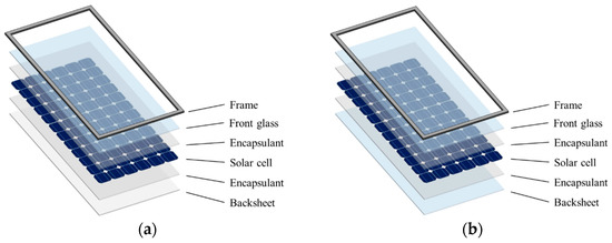
Figure 2.
PV module: (a) Glass–backsheet PV module; (b) Glass–glass PV module.
In summary, while cable-suspended PV systems present a promising structural configuration for photovoltaic applications, their wind-resistant design currently lacks adequate guidance from standards. Moreover, the mechanism by which PV modules contribute to structural stiffness within such systems remains unclear. This study addresses current limitations by using finite element analysis to investigate the mechanical behavior of mainstream glass–glass PV modules. A displacement decomposition method is used to identify how these modules contribute stiffness to the cable-suspended PV system. A high-fidelity model (HFM) is developed as a benchmark, and based on its torsional stiffness, an equivalent stiffness model (ESM) is established. This simplified model is then used to conduct wind-induced vibration analysis of the cable-suspended PV systems, and investigate the deformation behavior of PV modules under realistic operating conditions.
2. High-Fidelity Model for Glass–Glass PV Modules
The structure of a glass–glass PV module consists of two main components: the laminate and the frame. As shown in Figure 3, the laminate adopts a symmetric glass–glass configuration, composed sequentially, from the front to the back, of a front glass, an encapsulant layer, silicon solar cells, another encapsulant layer, and a back glass. The primary stiffness of the laminate is provided by the two glass layers, which protect the silicon solar cells from cracking or damage under mechanical loads. The encapsulant fills the interlayer space, forming an integrated composite structure and offering mechanical cushioning to enhance the module’s load-resisting capacity. The frame, made of aluminum alloy, significantly increases the module’s bending stiffness.
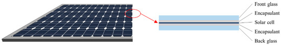
Figure 3.
Laminated structure of the glass–glass PV module.
As shown in Figure 4, the mainstream glass–glass PV modules currently used in PV systems in the Chinese market have dimensions of 2278 mm × 1134 mm × 35 mm. Both the front and back glass layers are made of 2 mm thick heat-strengthened glass. Based on this module specification, this study develops finite element models under different design strategies to investigate the mechanical performance of the glass–glass PV modules.
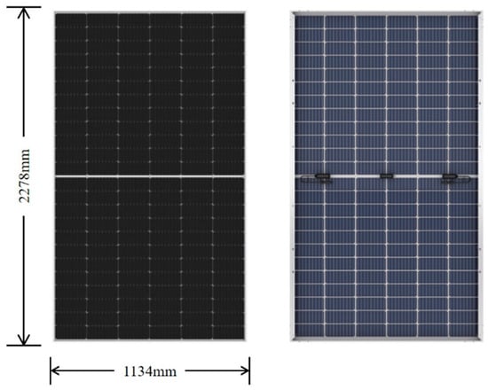
Figure 4.
Glass–glass PV module.
In current research and engineering practice for cable-suspended PV systems, researchers and designers typically adopt a modeling approach in which shell elements are created with geometric dimensions identical to the physical modules, and the material properties of glass are directly assigned to these elements [31]. This inaccurate simplified model (ISM) tends to overestimate the stiffness of PV modules, thereby compromising the accuracy of structural research and design. To better simulate the actual mechanical behavior of glass–glass PV modules under realistic conditions, a high-fidelity model (HFM) is developed in this study to serve as a reference for subsequent analyses.
In glass–glass PV modules, the silicon solar cells are thin and discretely distributed, with adjacent cells connected only by solder ribbons. As a result, the cell layer provides limited contribution to the overall stiffness of the module and can be neglected in the model, with only its gravitational load being considered. Based on this simplification, the mechanical model of the glass–glass module is illustrated in Figure 5. Under bending, relative slip occurs between the two glass layers; however, since the encapsulating layer provides both adhesion and a certain degree of shear stiffness, a coupling relationship exists between the translational degrees of freedom of the two glass layers in the mechanical model.
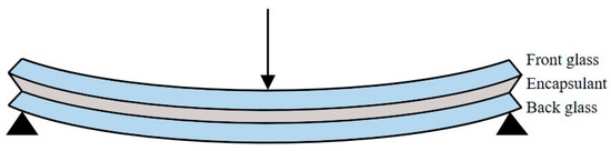
Figure 5.
Mechanical model of the glass–glass module.
The finite element simulation platform selected for this study is SAP2000 v24.0. The front and back glass are modeled using shell elements, while the aluminum frame of the PV module is represented by frame elements with a custom cross-section. The translational degrees of freedom between the glass layers are coupled using link elements, which also directly transmit shell deflection to simulate the mechanical behavior of the encapsulant. The finite element model is shown in Figure 6, and the material properties of each component are listed in Table 1. A mesh sensitivity analysis was conducted for the finite element model. The Grid Convergence Index (GCI) is set to 3%, that is, when the response change after further refinement is less than 3%, the model is confirmed to have converged. The shell element mesh size used at this time is approximately 23.7 mm × 23.7 mm.
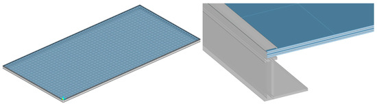
Figure 6.
Glass–glass PV modules of finite element high-fidelity model.

Table 1.
Material properties.
3. Stiffness Contribution Form of PV Modules in Cable-Suspended PV Systems
Due to the structural characteristics of the cable-suspended PV system, significant wind-induced vibrations can occur under wind loading, resulting in torsional displacements in the PV modules. Given the dynamic nature of this process, finite element time history analysis is required. However, the previously established high-fidelity finite element model is not suitable for such analysis due to its complexity and high computational cost. Therefore, a simplified model with equivalent stiffness is needed to perform a wind-induced vibration time history analysis of the cable-suspended PV system. Prior to developing this equivalent stiffness simplified model, this study first investigates the specific form in which PV modules contribute stiffness to the overall structure.
The finite element model of the cable-suspended PV system used in this study is shown in Figure 7. The system has a span of 29.1 m and a height of 4 m, with 24 glass–glass PV modules installed in a single span at a tilt angle of 15°. Beam and column members are modeled using frame elements. Meanwhile, the prestressed cables are represented by cable elements and fixed at both ends. Prestress is applied in the form of a target force of 60 kN. The glass–glass PV modules are modeled using the conventional approach (i.e., ISM), with material properties referenced from glass. However, to avoid overestimating the stiffness, which may obscure the deformation–force relationship and hinder the analysis of stiffness contribution, the elastic modulus of the modules is substantially reduced to allow for greater deformation under wind-induced vibration. The final assigned material properties are an elastic modulus of 7.2 GPa, a Poisson’s ratio of 0.22, and a mass corresponding to a module weight of 32.6 kg. The PV modules are connected to the cables via rigid links at four joints, simulating the clamped or bolted connections with the cable system. The wind loads used for the vibration analysis are derived from wind tunnel tests previously conducted by the authors [8].
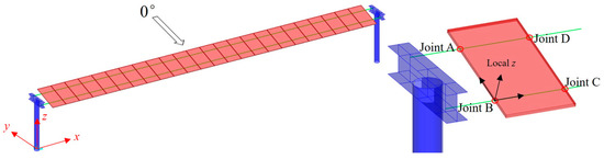
Figure 7.
Finite element model of the cable-suspended PV system.
Time history analysis under a 0° wind direction (suction) and a wind speed of 28.3 m/s (corresponding to a wind pressure of 0.5 kN/m2) yielded the local Z-direction (i.e., normal to the module surface) displacement responses of the four connection nodes on an edge-span glass–glass PV module, as shown in Figure 8. It is observed that the displacements of the four nodes are not synchronized, which indicates that the overall motion of the module comprises both rigid-body movement and elastic deformation.
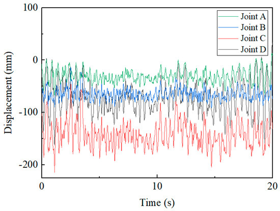
Figure 8.
Displacement time histories of four joints on edge-span glass–glass PV module.
To further analyze the motion patterns of PV modules, the local Z-direction displacement time histories of the four joints of a module can be treated as a displacement time history vector ; by selecting appropriate displacement modal vectors , this vector can be decomposed into combinations of different displacement modes, expressed as follows:
where is the displacement modal matrix; is the modal vector of the -th displacement modal vectors, reflecting the shape of each mode; is the displacement modal coordinate matrix; and denotes the modal coordinate time history of the -th displacement mode, indicating the contribution level of each mode to the overall motion.
Based on the above theory and considering the displacement characteristics of glass–glass PV modules on the cable-suspended PV system, a set of displacement modal vectors , , , is selected. These modal vectors correspond, respectively, to the vertical translation, rotation about the longitudinal axis, rotation about the transverse axis, and torsion of the module. The mode shapes corresponding to the modal vectors are illustrated in Figure 9. The modal vectors of the module and the corresponding displacement modal matrix are given as follows:

Figure 9.
Mode shapes: (a) Vertical translation; (b) Longitudinal rotation; (c) Transverse rotation; (d) Torsion.
The matrix is full-rank, and its vectors are linearly independent; therefore, it can be used to represent any displacement vector within the displacement vector space. Based on the above theory and methodology, the wind-induced vibrations of the module on the cable-suspended PV system can be decomposed.
By performing modal decomposition on the displacement vector shown in Figure 8, the corresponding modal coordinates under each mode can be obtained, as illustrated in Figure 10. It can be observed that, under this loading condition, the displacement of the edge-span glass–glass PV module is primarily governed by vertical translational motion, followed by rotations about the longitudinal and transverse axes. The contribution from torsional motion is the smallest. The rigid-body modes—including the vertical translation and the rotations about the longitudinal and transverse axes and , respectively—do not induce internal forces and are therefore excluded from subsequent analysis. The torsional mode , on the other hand, fully characterizes the deformation and force response of the glass–glass PV module under wind-induced vibrations in the context of a cable-suspended system. This indicates that the stiffness contribution of the PV module within the cable-suspended PV system manifests primarily through its torsional stiffness, which resists the structural deformation induced by wind loading.
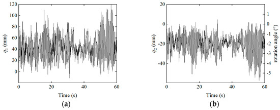
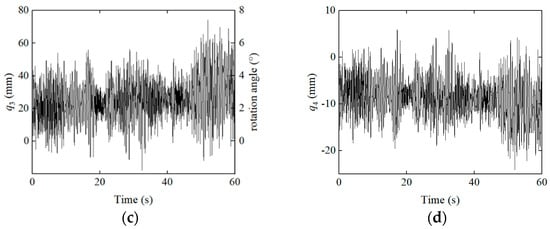
Figure 10.
Modal coordinate time histories: (a) Vertical translation; (b) Longitudinal rotation; (c) Transverse rotation; (d) Torsion.
4. Equivalent Stiffness Model for Glass–Glass PV Modules
With the stiffness contribution mechanism of PV modules to cable-suspended PV system clarified, an equivalent stiffness model (ESM) is developed. Using the high-fidelity model (HFM) of the glass–glass PV module as the reference, the ESM is calibrated to match the mass and torsional stiffness of the HFM. Through computation, the geometric and material properties of the ESM are determined as follows: the geometry is identical to that of the actual module (2278 mm × 1134 mm × 35 mm); the material density is 360.6 kg/m3, corresponding to a module weight of 32.6 kg; the elastic modulus is 0.525 GPa; and the Poisson’s ratio is 0.3. Figure 11a presents the displacement–reaction force curves under torsion for both the HFM and the ESM, showing good agreement. This indicates that the torsional stiffness of the ESM is equivalent to that of the HFM. Additionally, Figure 11b compares the torsional displacement–reaction curves for three models. To facilitate comparison, logarithmic axes are used in the plot due to the substantial stiffness difference among the models. It can be clearly seen that the inaccurate simplified model (ISM) exhibits a much higher stiffness than the other two, confirming that this modeling approach significantly overestimates the stiffness of PV modules.
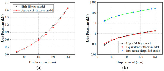
Figure 11.
Displacement–reaction force curve: (a) HFM and ESM; (b) Three models.
Finite element models of the cable-suspended PV system are developed using the HFM, ESM, and ISM approaches, respectively. Figure 12 presents the first vertical bending and torsional modes obtained from each modeling strategy. It can be observed that, for vertical bending deformation, the three models exhibit good consistency in both modal shapes and natural frequencies, with only minor frequency differences. In contrast, for torsional modes, the ESM and HFM show close agreement, while the ISM differs significantly. This discrepancy arises because the ISM assigns much higher stiffness to the PV modules than they possess in reality, resulting in an unrealistically large contribution to the system’s torsional stiffness and consequently shifting the first torsional mode to a much higher frequency.
Figure 12.
Mode shapes and frequencies of different models: (a) HFM—First vertical bending mode (1.167 Hz); (b) HFM—First torsional mode (1.071 Hz); (c) ESM—First vertical bending mode (1.159 Hz); (d) ESM—First torsional mode (1.056 Hz); (e) ISM—First vertical bending mode (1.170 Hz); (f) ISM—First torsional mode (2.268 Hz).
Based on the above analysis, the ESM can be considered a reliable substitute for the HFM in dynamic wind-induced vibration analyses of a cable-suspended PV system, with a high level of accuracy. A finite element wind-induced vibration analysis is conducted using the ESM under the same wind speed of 28.3 m/s (corresponding to a wind pressure of 0.5 kN/m2). The resulting modal coordinates of the glass–glass PV modules under both wind suction and wind pressure conditions are presented in Figure 13 and Figure 14. To further investigate the wind-induced vibration characteristics of the cable-suspended PV system, the figures include the modal coordinate results for both edge-span and mid-span glass–glass PV modules.
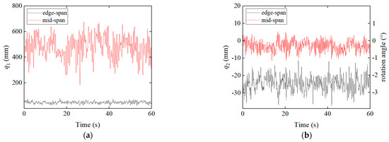
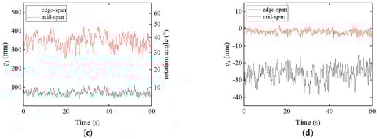
Figure 13.
Mid-span and edge-span PV modules and their modal coordinate time histories (28.3 m/s, suction): (a) Vertical translation; (b) Longitudinal rotation; (c) Transverse rotation; (d) Torsion.
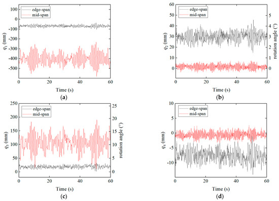
Figure 14.
Mid-span and edge-span PV modules and their modal coordinate time histories (28.3 m/s, pressure): (a) Vertical translation; (b) Longitudinal rotation; (c) Transverse rotation; (d) Torsion.
It can be observed that the mid-span PV modules exhibit significantly greater vertical translation and rotation about the transverse axis compared to the edge-span modules, whereas rotation about the longitudinal axis and torsion are more pronounced in the edge-span modules. From a mechanics perspective, this indicates that the edge-span modules in the cable-suspended PV system are subjected to greater torsional displacements, resulting in higher internal mechanical stresses. Moreover, both the rotation about the transverse axis and torsional response of the modules are substantially smaller under wind pressure than under wind suction. At the system level, this corresponds to the significantly lower overall torsional deformation of the cable-suspended structure under wind pressure. This phenomenon can be explained as follows: in the initial state, the suspension cables of the PV system sag downward under gravity. When the system is subjected to upward wind suction, the cable tension decreases, leading to a reduction in lateral stiffness. Combined with the non-uniform distribution of wind loads on the PV modules [32,33], the upper portion of the modules experiences greater uplift forces, causing the higher-positioned cable to rise more than the lower one. This differential displacement results in a further reduction in the lateral stiffness of the higher cable and amplifies its uplift, leading to greater torsional deformation at the structural level. In contrast, under wind pressure, although the lower part of the module experiences stronger downward forces due to load asymmetry, the entire structure displaces downward, increasing the tension in both cables simultaneously and avoiding any unilateral stiffness loss. Therefore, in the engineering design of a cable-suspended PV system, particular attention should be paid to enhancing the system’s torsional resistance, especially to mitigate the risk of potential failure in the edge-span modules caused by excessive torsional displacement.
5. Conclusions
In this study, a finite element–based investigation of the mechanical performance of a cable-suspended PV system and glass–glass PV modules is conducted. The analysis revealed the stiffness contribution mechanism of the modules within the cable-suspended PV system, compared the dynamic characteristics across three modeling strategies, and examined the wind-induced vibration characteristics of the system based on the equivalent stiffness model (ESM) using a displacement decomposition method. The main conclusions are as follows:
- (1)
- The displacement decomposition method can be applied to decouple the wind-induced vibrations of the glass–glass PV module on the cable-suspended PV system, thereby enabling the study of the module’s deformation. The PV module contributes to the overall structural stiffness of the cable-suspended PV system through its torsional stiffness.
- (2)
- The ESM and HFM are equivalent in terms of dynamic characteristics, while the ISM significantly overestimates the torsional stiffness of the module. The ESM can be used as a substitute for the HFM in wind vibration analysis, simplifying the modeling process and saving computational resources.
- (3)
- The torsion of the cable-suspended PV system under wind suction is significantly greater than that under wind pressure, and the torsion of the edge-span PV module is larger than that of the mid-span PV module.
6. Study Recommendations and Future Work
6.1. Study Recommendations
Based on the findings of this study, it is recommended that design standards incorporate the torsional stiffness of PV modules into wind-induced vibration analysis, particularly for large-span PV systems installed in areas prone to strong wind action.
Current design practices typically misjudge the stiffness contribution of PV modules, particularly in torsional deformation modes. Including this factor in structural analysis by using ESM will enable more accurate predictions of the dynamic response. In addition, it can also improve the overall reliability and safety of PV system designs without added computational cost.
6.2. Future Work
This study possesses certain limitations in some aspects. In light of these constraints, the following potential directions for future research are proposed:
- (1)
- The mechanical properties of the glass–glass module are discussed only through the finite element method in this study. Subsequent research could conduct mechanical performance tests on glass–glass modules to accurately obtain the module stiffness for the verification and calibration of the ESM.
- (2)
- The thickness of the encapsulant layer and the geometric dimensions of the modules can influence the stiffness of the modules. This study only addresses glass–glass modules of a specific size. Future research could comprehensively explore these variables to gain a more scientific and thorough understanding of the stiffness of glass–glass modules.
- (3)
- This study does not consider the long-term aging behavior of encapsulation materials under environmental factors such as temperature fluctuations, ultraviolet radiation, and humidity. Subsequent research could investigate this aspect to understand the dynamic changes in the mechanical properties of the modules over their service life.
Author Contributions
Conceptualization, G.H. and H.X.; methodology, G.H. and H.X.; software, G.H.; validation, G.H. and H.X.; formal analysis, G.H.; investigation, G.H. and H.X.; resources, H.X.; data curation, G.H. and H.X.; writing—original draft preparation, G.H.; writing—review and editing, H.X.; visualization, G.H.; supervision, H.X.; project administration, H.X.; funding acquisition, G.H. and H.X. All authors have read and agreed to the published version of the manuscript.
Funding
The work described in this paper was partially supported by the National Natural Science Foundation of China (project no. 51978614).
Data Availability Statement
The original contributions presented in this study are included in the article. Further inquiries can be directed to the corresponding author.
Conflicts of Interest
The authors declare no conflicts of interest.
Nomenclature
The following symbols are used in this manuscript:
| No. | Symbol | Description |
| 1 | The joint displacement matrix | |
| 2 | The local Z-direction displacements of module’s joints | |
| 3 | The displacement modal matrix | |
| 4 | The modal vector of the -th displacement modal vectors | |
| 5 | The displacement modal coordinate matrix | |
| 6 | The modal coordinate of the -th displacement mode | |
| 7 | Time |
Abbreviations
The following abbreviations are used in this manuscript:
| PV | Photovoltaic |
| HFM | High-fidelity model |
| ESM | Equivalent stiffness model |
| ISM | Inaccurate simplified model |
References
- IRENA. Renewable Capacity Statistics 2025; International Renewable Energy Agency: Abu Dhabi, United Arab Emirates, 2025; pp. 25–28. [Google Scholar]
- IEC 61215-2:2021; Terrestrial Photovoltaic (PV) Modules—Design Qualification and Type Approval. IEC: Geneva, Switzerland, 2021.
- IEC 63092-2:2020; Photovoltaics in Buildings—Part 2: Requirements for Building-Integrated Photovoltaic Systems. IEC: Geneva, Switzerland, 2020.
- IEC 62817:2014; Photovoltaic Systems—Design Qualification of Solar Trackers. IEC: Geneva, Switzerland, 2014.
- ASCE 7-22; Minimum Design Loads and Associated Criteria for Buildings and Other Structures. American Society of Civil Engineers: Reston, VA, USA, 2022.
- NB/T 10115-2018; Code for Design of Photovoltaic Modules Support Structures. China Planning Press: Beijing, China, 2018.
- T/CSEE 0394-2023; Design Specification for Flexible Support Structures of Photovoltaie Modules. Chinese Society for Electrical Engineering: Beijing, China, 2023.
- Li, J.; Hong, G.; Xu, H. Wind load effects and gust loading factor for cable-suspended photovoltaic structures. Energies 2023, 17, 38. [Google Scholar] [CrossRef]
- Kim, Y.; Tamura, Y.; Yoshida, A.; Ito, T.; Shan, W.; Yang, Q. Experimental investigation of aerodynamic vibrations of solar wing system. Adv. Struct. Eng. 2018, 21, 2217–2226. [Google Scholar] [CrossRef]
- Tamura, Y.; Kim, Y.C.; Yoshida, A.; Itoh, T. Wind-induced vibration experiment on solar wing. In Proceedings of the MATEC Web of Conferences, Zurich, Switzerland, 19–21 October 2015; p. 04006. [Google Scholar] [CrossRef]
- He, X.; Ding, H.; Jing, H.; Zhang, F.; Wu, X.; Weng, X. Wind-induced vibration and its suppression of photovoltaic modules supported by suspension cables. J. Wind Eng. Ind. Aerodyn. 2020, 206, 104275. [Google Scholar] [CrossRef]
- Liu, J.; Li, S.; Luo, J.; Chen, Z. Experimental study on critical wind velocity of a 33-meter-span flexible photovoltaic support structure and its mitigation. J. Wind Eng. Ind. Aerodyn. 2023, 236, 105355. [Google Scholar] [CrossRef]
- Xu, H.; Ding, K.; Shen, G.; Du, H.; Chen, Y. Experimental investigation on wind-induced vibration of photovoltaic modules supported by suspension cables. Eng. Struct. 2024, 299, 117125. [Google Scholar] [CrossRef]
- He, X.-H.; Ding, H.; Jing, H.-Q.; Wu, X.-P.; Weng, X.-J. Mechanical characteristics of a new type of cable-supported photovoltaic module system. Sol. Energy 2021, 226, 408–420. [Google Scholar] [CrossRef]
- Zhu, Y.F.; Huang, Y.; Xu, C.; Xiao, B.; Chen, C.H.; Yao, Y. Analysis of wind-induced vibration effect parameters in flexible cable-supported photovoltaic systems: A case study on ground anchor with steel cables. Case Stud. Constr. Mater. 2024, 20, e03368. [Google Scholar] [CrossRef]
- Knausz, M.; Oreski, G.; Schmidt, M.; Guttmann, P.; Berger, K.; Voronko, Y.; Eder, G.; Koch, T.; Pinter, G. Thermal expansion behavior of solar cell encapsulation materials. Polym. Test. 2015, 44, 160–167. [Google Scholar] [CrossRef]
- Gabor, A.M.; Ralli, M.; Montminy, S.; Alegria, L.; Bordonaro, C.; Woods, J.; Felton, L.; Davis, M.; Atchley, B.; Williams, T. Soldering induced damage to thin Si solar cells and detection of cracked cells in modules. In Proceedings of the 21st European Photovoltaic Solar Energy Conference, Dresden, Germany, 4–8 September 2006; pp. 4–8. [Google Scholar]
- Kraemer, F.; Seib, J.; Peter, E.; Wiese, S. Mechanical stress analysis in photovoltaic cells during the string-ribbon interconnection process. In Proceedings of the 2014 15th International Conference on Thermal, Mechanical and Mulit-Physics Simulation and Experiments in Microelectronics and Microsystems (EuroSimE), Ghent, Belgium, 7–9 April 2014; pp. 1–7. [Google Scholar] [CrossRef]
- Rendler, L.C.; Romer, P.; Beinert, A.J.; Walter, J.; Stecklum, S.; Kraft, A.; Eitner, U.; Wiese, S. Thermomechanical stress in solar cells: Contact pad modeling and reliability analysis. Sol. Energy Mater. Sol. Cells 2019, 196, 167–177. [Google Scholar] [CrossRef]
- Köntges, M.; Siebert, M.; Morlier, A.; Illing, R.; Bessing, N.; Wegert, F. Impact of transportation on silicon wafer-based photovoltaic modules. Prog. Photovolt. Res. Appl. 2016, 24, 1085–1095. [Google Scholar] [CrossRef]
- Köntges, M.; Kurtz, S.; Packard, C.E.; Jahn, U.; Berger, K.A.; Kato, K.; Friesen, T.; Liu, H.; Van Iseghem, M.; Wohlgemuth, J. Review of Failures of Photovoltaic Modules; IEA-PVPS T13-01:2014; International Energy Agency Photovoltaic Power Systems Programme: Redfern, Australia, 2014; p. 56. [Google Scholar]
- Buerhop-Lutz, C.; Winkler, T.; Fecher, F.W.; Bemm, A.; Hauch, J.; Camus, C.; Brabec, C. Performance analysis of pre-cracked PV-modules at realistic loading conditions. In Proceedings of the 33rd European PV-SEC, 5CO, Amsterdam, The Netherlands, 25–29 September 2017; Volume 8, pp. 1451–1456. [Google Scholar]
- Mathiak, G. PV module damages caused by hail impact-field experience and lab tests. In Proceedings of the 31st European Photovoltaic Solar Energy Conference and Exhibition, Hamburg, Germany, 14–18 September 2015; pp. 1915–1919. [Google Scholar]
- Mathiak, G.; Sommer, J.; Herrmann, W.; Bogdanski, N.; Althaus, J.; Reil, F. PV module damages caused by hail impact and non-uniform snow load. In Proceedings of the 32nd European Photovoltaic Solar Energy Conference and Exhibition, Munich, Germany, 20–24 June 2016; pp. 1692–1696. [Google Scholar]
- Kajari-Schröder, S.; Kunze, I.; Eitner, U.; Köntges, M. Spatial and orientational distribution of cracks in crystalline photovoltaic modules generated by mechanical load tests. Sol. Energy Mater. Sol. Cells 2011, 95, 3054–3059. [Google Scholar] [CrossRef]
- Schneller, E.J.; Gabor, A.M.; Lincoln, J.; Janoch, R.; Anselmo, A.; Walters, J.; Seigneur, H. Evaluating solar cell fracture as a function of module mechanical loading conditions. In Proceedings of the 2017 IEEE 44th Photovoltaic Specialist Conference (PVSC), Washington, DC, USA, 25–30 June 2017; pp. 2897–2901. [Google Scholar] [CrossRef]
- Dong, J.; Yang, H.; Lu, X.; Zhang, H.; Peng, J. Comparative study on static and dynamic analyses of an ultra-thin double-glazing PV module based on FEM. Energy Procedia 2015, 75, 343–348. [Google Scholar] [CrossRef]
- Dietrich, S.; Pander, M.; Ebert, M.; Bagdahn, J. Mechanical assessment of large photovoltaic modules by test and finite element analysis. In Proceedings of the 23rd European Photovoltaic Solar Energy Conference, Valencia, Spain, 1–5 September 2008. [Google Scholar]
- Shitanoki, Y.; Bennison, S.J.; Koike, Y. A rational strength prediction approach to the design of double-glass photovoltaic modules. IEEE J. Photovolt. 2014, 4, 1071–1078. [Google Scholar] [CrossRef]
- Joshi, D.; Webb, J.E. Mechanical Reliability Calculations for the Thin Specialty Glass PV Solar Panels. Int. J. Struct. Glass Adv. Mater. Res. 2019, 3, 87–97. [Google Scholar] [CrossRef]
- Chen, Q.; Niu, H.; Li, H.; Jiang, D. Aerodynamic stability and interference effect on a flexible photovoltaic based on wind tunnel test with aeroelastic model. J. Wind Eng. Ind. Aerodyn. 2023, 44, 153–161. [Google Scholar] [CrossRef]
- Ma, W.; Chai, X.; Zhao, H.; Ma, C. A study on distribution coefficient of a flexible photovoltaic support cable based on an eccentric moment wind load distribution model. J. Vib. Shock 2021, 40, 305–310. [Google Scholar] [CrossRef]
- Yemenici, O.; Aksoy, M.O. An experimental and numerical study of wind effects on a ground-mounted solar panel at different panel tilt angles and wind directions. J. Wind Eng. Ind. Aerodyn. 2021, 213, 104630. [Google Scholar] [CrossRef]
Disclaimer/Publisher’s Note: The statements, opinions and data contained in all publications are solely those of the individual author(s) and contributor(s) and not of MDPI and/or the editor(s). MDPI and/or the editor(s) disclaim responsibility for any injury to people or property resulting from any ideas, methods, instructions or products referred to in the content. |
© 2025 by the authors. Licensee MDPI, Basel, Switzerland. This article is an open access article distributed under the terms and conditions of the Creative Commons Attribution (CC BY) license (https://creativecommons.org/licenses/by/4.0/).