Article

An Acceleration-Observer-Based Position and Load Torque Estimation Method for Wind Turbine with Sensor Faults

1
School of Mechano-Electronic Engineering, Xidian University, Xi’an 710071, China
2
Ming Yang Smart Energy Group Limited, Zhongshan 528437, China
*
Author to whom correspondence should be addressed.
Energies 2025, 18(11), 2787; https://doi.org/10.3390/en18112787
Submission received: 28 March 2025 / Revised: 18 May 2025 / Accepted: 19 May 2025 / Published: 27 May 2025
(This article belongs to the Section F3: Power Electronics)

Abstract

:
Speed, position, and load torque information are crucial for the stable control of wind turbines, and existing control methods heavily rely on position and torque sensors to obtain these parameters. However, under the extreme scenario of sensor faults, the performance of these control methods deteriorates significantly, often leading to instability. In this paper, an acceleration-observer-based position and load torque estimation method is proposed for wind turbines, which effectively mitigates the impact of sensor faults. The position, speed, and acceleration estimators are developed based on current and voltage sensors information instead of position and load torque sensors. Then, the load torque can be calculated directly through the current and acceleration information. Thereby, the proposed method reduces reliance on position and load torque sensors for stable control and enables effective load torque estimation even under sensor faults. Rigorous theoretical analysis is provided to show that the proposed estimation method is stable and can effectively estimate position, speed, acceleration, and load torque information. Our numerical simulation results demonstrate that the proposed method exhibits excellent dynamics, accuracy, and robustness under various operating conditions.

1. Introduction

The limited availability of fossil fuels and the increasing demands of population growth and industrialization present significant challenges to traditional energy systems [1]. According to the World Energy Organization, fossil fuels account for 79 % of global energy supply, but their reserves are depleting rapidly [2]. As energy demand continues to rise and environmental factors affect supply, the stability of economies is at risk, making a sustainable energy supply essential [3]. In this context, wind energy has become one of the most attractive renewable energy sources, due to its abundance and the advancement of supporting technologies [4,5,6]. In recent decades, wind turbines have gained increasing recognition for their cost effectiveness, higher installed capacities, and utilization of abundant wind resources, making them a key contributor to meeting the growing global demand for renewable energy [7,8].
The mathematical model of wind turbines is characterized by strong coupling, nonlinearity, and multi-variable interactions. The combination of strong nonlinearity and complex operational environments poses a significant challenge in designing the controllers [9,10]. Generally, variable-speed wind turbines operate within five distinct regions, as shown in Figure 1, and these regions are distinguished based on the power curve. That is to say, the prevailing wind conditions determine the operation regions. And under different operation regions, the control objectives are different [11]. Among them, the optimal tip–speed ratio region is one of the most significant operation regions since it covers a wide operating range. In this region, the control objective is to maintain the operating state along the curve of the maximum power coefficient C p m a x , thereby ensuring optimal wind energy capture.
In the optimal tip–speed ratio region, changes in wind speed lead to variations in both load torque and the target speed. The relationship between wind speed, load torque, and turbine speed satisfies the following equation, as shown below:
T a = P Ω r = 0.5 C p m a x ρ S v x 3 Ω r λ o p t = Ω r R v x
where T a , P , Ω r , ρ , S , R , v x , λ o p t represent the torque of the wind turbine, the power extracted from the wind, the wind turbine speed, the air density, the swept area of the turbine blades, the radius of the turbine blades, the equivalent wind speed, and the optimal tip–speed ratio, respectively.
Therefore, the commonly used control strategy for wind turbines operating in this region is the torque–speed dual-loop control [12,13,14]. This control strategy relies heavily on accurate information about rotor speed, position, and load torque. Typically, this position and speed information are obtained through the position sensors, and the load torque is obtained through the torque sensors [15,16]. However, wind turbines operate in harsh and complex environments, and these sensors can easily degrade and fail [17,18]. There are many speed and position estimation methods available in the literature, such as fundamental excitation methods and saliency and signal injection methods [19,20,21,22,23,24], However, torque estimation methods, especially their application in wind turbines, are rarely reported [25,26]. Furthermore, within the optimal tip–speed ratio region, it is necessary to continuously adjust the turbine’s rotational speed and torque in response to varying wind speeds. This places stringent demands on the performance of position–speed estimation methods and torque estimation methods.
In this paper, an acceleration-observer-based position, speed, and load torque estimation method is proposed, which operates effectively without relying on position and torque sensors, making it particularly suitable for scenarios involving sensor faults in wind turbines. The proposed estimation method only relies on the current and voltage sensors. Therefore, it is particularly suitable for the harsh working conditions and operating environments of wind turbines. A sliding mode observer (SMO) is adopted to construct the current observers, and the position error between the estimated and actual positions is derived. Based on the position error information, a third-order observer is developed to estimate the speed, position, and the speed change rate (acceleration). Then, the load torque can be calculated directly through the current and acceleration information. The proposed estimation method can accurately estimate the acceleration, and it can effectively suppress the effect of the wind speed change through the estimated acceleration. Thereby, the proposed method reduces reliance on position and load torque sensors in stable control and enables effective load torque estimation even under sensor faults. Rigorous theoretical analysis is provided to show that the proposed estimation method is stable and can effectively estimate position, speed, acceleration, and load torque information. Simulation results are also provided to demonstrate that the proposed method exhibits excellent dynamics, accuracy, and robustness under various operating conditions.
The rest of this paper is organized as follows. In Section 2, an acceleration-observer-based position and load torque estimation method is provided, and a systematical analysis of its stability is included. Section 3 presents the numerical simulation results, which verify the effectiveness of the proposed method. Finally, Section 4 concludes this paper.

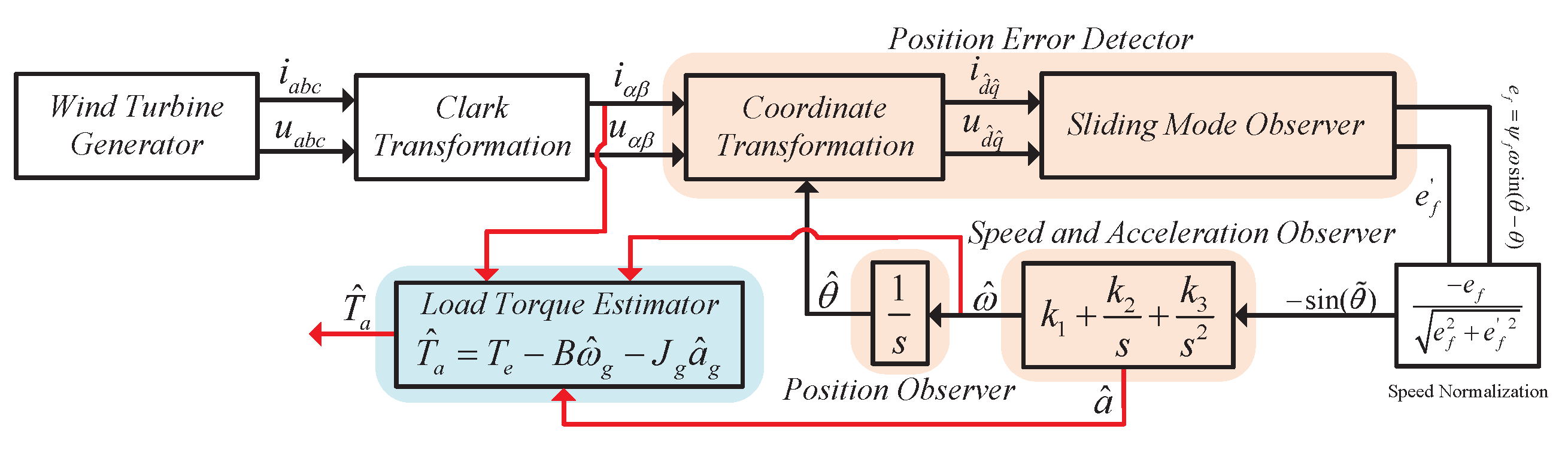
2. Proposed Position and Load Torque Estimation Method

Position sensor faults together with change of load torque greatly challenge the stable control of a wind turbine, as accurate position and load torque information are the fundamental insurance of the stable operation of a wind turbine. In this section, position, speed, and load torque estimation methods are developed for wind turbines with position sensor faults. A sliding mode observer (SMO) is adopted to obtain the difference between the actual position and the estimated position. Type-3 phase-locked loop (PLL) technology is employed to suppress the effect of the load torque change, and position, speed, and acceleration are obtained through a type-3 PLL-based observer. Then, the load torque is calculated directly through the current and acceleration information. The proposed position and load torque estimation method as shown in Figure 2 contains three parts: the position error-detection part, the position, speed, and acceleration-estimation part, and the load torque-estimation part.

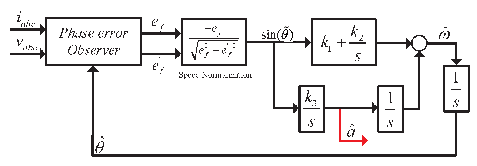
2.1. Position Error Detection

The current and voltage equations of a permanent magnet synchronous generator (PMSG) in the α β reference frame can be expressed as:
d d t i α i β = 1 L s u α u β R s L s i α i β 1 L s ψ f ω s i n θ c o s θ
where i α , i β , u α , and u β are the currents and voltages of the PMSG in the α - β reference frame; R s and ψ f are the stator resistance and permanent magnet flux linkage, respectively; θ is the electrical position of the rotor; L s is the stator inductance; and ω is the electrical angular speed.
Since the actual rotor position and speed are unknown during sensor faults, it is necessary to establish an estimated d q reference frame ( d ^ q ^ -reference frame). When the actual rotor position θ matches its estimated value θ ^ , the d ^ q ^ -reference frame becomes aligned with actual d q reference frame. The symbol ‘^’ denotes estimated values. Based on the estimated rotor position θ ^ , the following Park transformation can be derived:
i d ^ i q ^ = c o s θ ^ s i n θ ^ s i n θ ^ c o s θ ^ i α i β
where θ ^ is the estimated position of the PMSG.
Then, the current and voltage equations of the PMSG in the d ^ q ^ reference frame can be derived as
d d t i d ^ i q ^ = 1 L s u d ^ u q ^ + R s L s ω ^ ω ^ R s L s i d ^ i q ^ 1 L s e f e f
where i d ^ , i q ^ , u d ^ , u q ^ represent the currents and voltages of the PMSG in the d ^ - q ^ reference frame; ω ^ is the estimated angular speed. The back-EMF components are given by e f = ψ f ω sin θ ˜ and e f = ψ f ω cos θ ˜ . Note that θ ˜ = θ ^ θ is the position error between the estimated position θ ^ and the actual position θ .
It is clear that the current and voltage Equation (3) contains the following position error terms:
e f = ψ f ω s i n θ ˜ e f = ψ f ω c o s θ ˜
And these position errors can be used to estimate the position. In the following, the sliding mode observer is constructed based on (3), in order to obtain the above position error terms:
d d t i ^ d ^ i ^ q ^ = 1 L s u d ^ u q ^ + R s L s ω ^ ω ^ R s L s i ^ d ^ i ^ q ^ 1 L s e ^ f e ^ f
e ^ f e ^ f = h sign ( i ^ d ^ i d ^ ) sign ( i ^ q ^ i q ^ )
where i ^ d ^ and i ^ q ^ are the estimations of the currents i d ^ and i q ^ , respectively; e ^ f and e ^ f are the estimations of the position error terms e f and e f , respectively; and sign(·) represents the sign function. The parameter h represents the sliding mode gain, which is a positive constant. It must satisfy the following condition to ensure the asymptotic stability of the sliding mode observer:
h > e f R s i ˜ d ^ + L s ω ^ s i g n ( i ^ d ^ i d ^ ) · i ˜ q ^
h > e f R s i ˜ q ^ + L s ω ^ s i g n ( i ^ q ^ i q ^ ) · i ˜ d ^
The stability and convergence of the proposed estimators are demonstrated as below. Let i ˜ d ^ = i ^ d ^ i d ^ and i ˜ q ^ = i ^ q ^ i q ^ . Then, according to (3) and (5), we obtain
d d t i ˜ d ^ i ˜ q ^ = R s L s ω ^ ω ^ R s L s i ˜ d ^ i ˜ q ^ + 1 L s e f e f h L s sign i ˜ d ^ sign i ˜ q ^
Define the sliding surface functions as
s 1 = i ˜ d ^ s 2 = i ˜ q ^
Construct the Lyapunov function:
L ( s 1 , s 2 ) = 1 2 s 1 2 + 1 2 s 2 2
Based on (9), it is deduced that
L ˙ ( s 1 , s 2 ) = s 1 s ˙ 1 + s 2 s ˙ 2 = s 1 L s R s s 1 + L s ω ^ i ˜ q ^ + e f h sign ( s 1 ) + s 2 L s R s s 2 + L s ω ^ i ˜ d ^ + e f h sign ( s 2 )
Due to parameter h satisfying Equations (7) and (8), Equation (12) yields L ˙ ( s 1 , s 2 ) 0 . In addition, L ˙ ( s 1 , s 2 ) = 0 only when s 1 = s 2 = 0 simultaneously. Consequently, the system (9) is globally asymptotically stable at its unique equilibrium point (0,0), and lim t s 1 = 0 , lim t s 2 = 0 . In addition, lim t s ˙ 1 = 0 and lim t s ˙ 2 = 0 . According to (9), it is derived that
lim t e ^ f = e f and lim t e ^ f = e f

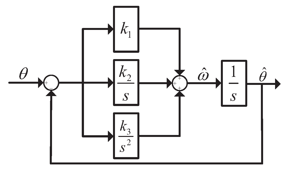
2.2. Speed, Position, and Acceleration Estimations

Load torque change in a wind turbine results in a change of the speed. Therefore, the accuracy of the speed change rate influences not only the position estimation but also the load torque estimation. In this section, a speed, position, and speed change rate (acceleration) estimation method is proposed. A block diagram of the proposed estimator is shown in Figure 3. The proposed estimator contains four parts: the speed-normalization part, the acceleration-estimator part, the speed-estimator part, and the position-estimator part. According to the speed normalization, it is deduced that
sin θ ˜ = e f e f 2 + e f 2
Then, based on Figure 3, the acceleration, speed, and position estimation can be derived as follows:
θ ^ = ω ^ d t ω ^ = k 1 sin θ ˜ k 2 sin θ ˜ d t + a ^ d t a ^ = k 3 sin θ ˜ d t
where θ ^ , ω ^ , and a ^ are the estimations of the position, speed, and acceleration of the wind turbine. Let ω ˜ = ω ^ ω and a ˜ = a ^ ω ˙ . The motion equations of the wind turbine satisfy
θ ˙ = ω J g ω ˙ = T e T a
where T a is the load torque, T e is the electromagnetic torque, and J g is the moment of inertia. We denote the speed change rate as a—that is, a = ω ˙ . Then, according to the estimators (15), we have
θ ˜ ˙ = ω ˜ ω ˜ ˙ = k 1 ω ˜ c o s θ ˜ s i n θ ˜ + a ˜ a ˜ ˙ = k 3 s i n θ ˜
The small-signal analysis method is adopted to analyze the wind turbine’s stability performance. The estimation error satisfies the following equations:
s i n θ ˜ θ ˜ c o s θ ˜ 1
Then, (17) is modified as
θ ˜ ˙ = ω ˜ ω ˜ ˙ = k 1 ω ˜ k 2 θ ˜ + a ˜ a ˜ ˙ = k 3 θ
Based on the discussion above, the equations of state can be established as
θ ˜ ˙ ω ˜ ˙ a ˜ ˙ = 0 1 0 k 2 k 1 1 k 3 0 0 θ ˜ ω ˜ a ˜
The eigenvalue equation of the coefficient matrix in (20) can be expressed as
f ( λ ) = λ 3 + k 1 λ 2 + k 2 λ + k 3
To ensure the estimator remains stable, the three poles should be designed to lie on the left half-plane of the s-domain, with negative real parts. Then, by applying the Routh–Hurwitz stability criterion, k 1 , k 2 , k 3 should satisfy
k 3 k 1 · k 2 k 1 < 0 k 3 < k 1 · k 2
Additionally, the load torque estimation method can be proved to achieve zero-error estimation under continuous wind speed variation, since the type-3 PLL effectively handles frequency ramp issues.
Figure 4 shows the small-signal model of the type-3 PLL; the open-loop transfer function can be expressed as
G o l ( s ) = k 1 s 2 + k 2 s + k 3 s 3
Then, the phase estimation error with the frequency ramp can be calculated through the final value theorem as
Δ θ e s s = lim s 0 s · K s 3 · 1 1 + G o l ( s ) = lim s 0 K s s 3 + k 1 s 2 + k 2 s + k 3 = 0
We have shown that the new loop filter (LF) in the type-3 PLL has two poles compared with the original scheme; in this case, the frequency ramp issue can be addressed, since the new control system is of type-3, and zero-error estimation of the relative variables can be obtained under the condition of continuous wind speed variation.

2.3. The Load Torque Estimation

Based on the speed change rate, the load torque can be estimated through the motion equation of the wind turbine. The speed dynamic equation of the wind turbine can be expressed as below. The equation is established under the assumptions that friction torques (such as viscous and Coulomb friction) are neglected, and the shaft between the motor and the load is assumed to be rigid:
J g d ω g d t = 3 2 p n ( ψ α i β ψ β i α ) T a
According to the definition of acceleration, the load torque can be calculated as follows:
T a = 3 2 p n ( ψ α i β ψ β i α ) J g a
Therefore, according to the estimation of the acceleration (15), the load torque can be estimated through following equation:
T ^ a = 3 2 p n ( ψ α i β ψ β i α ) J g a ^ = 3 2 p n ( ψ α i β ψ β i α ) + J g k 3 sin θ ˜ d s

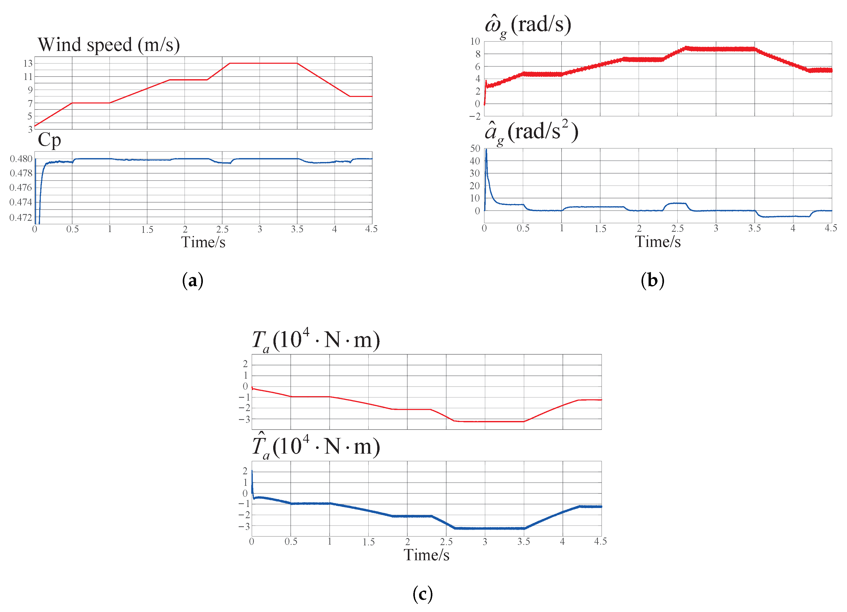
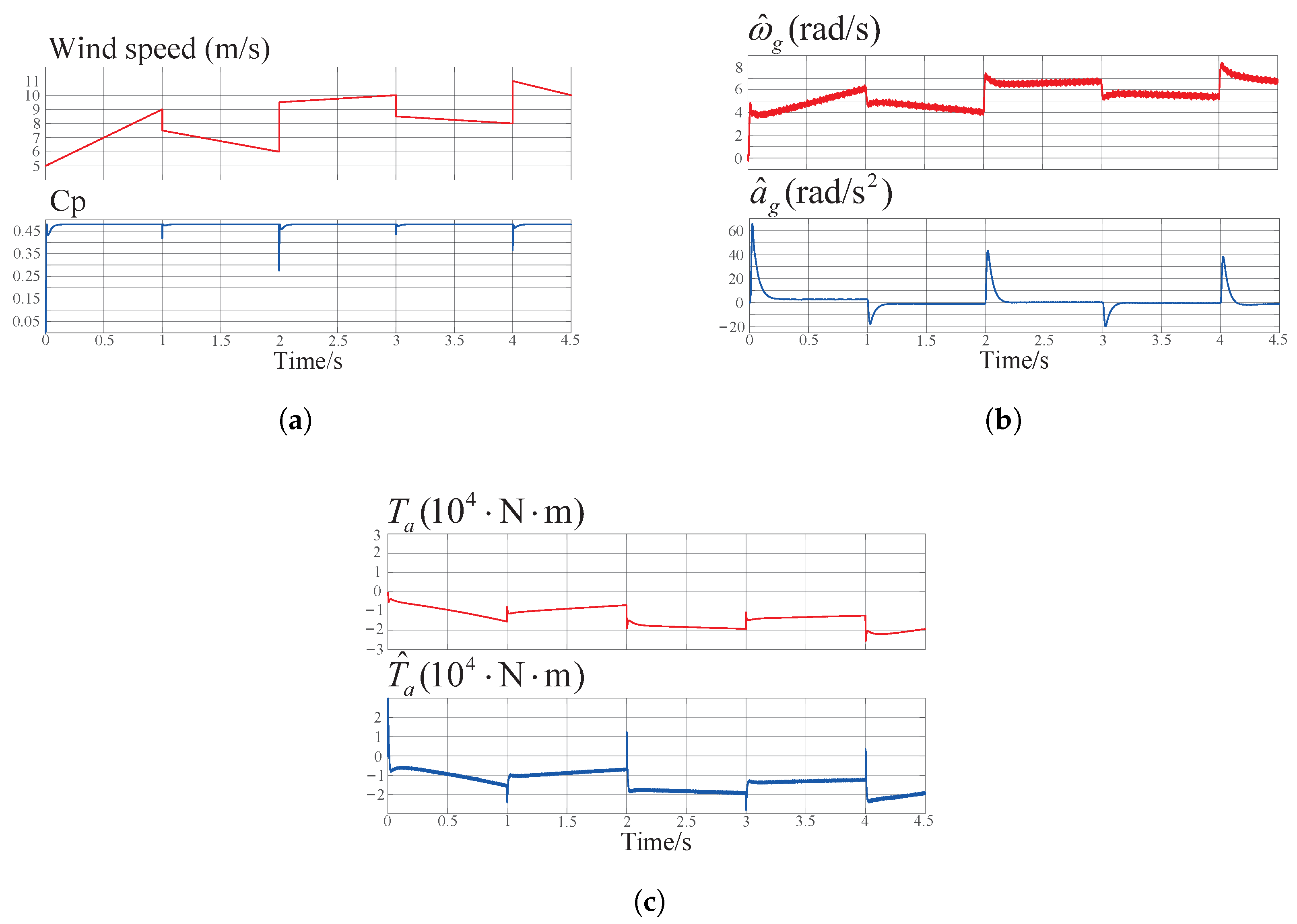
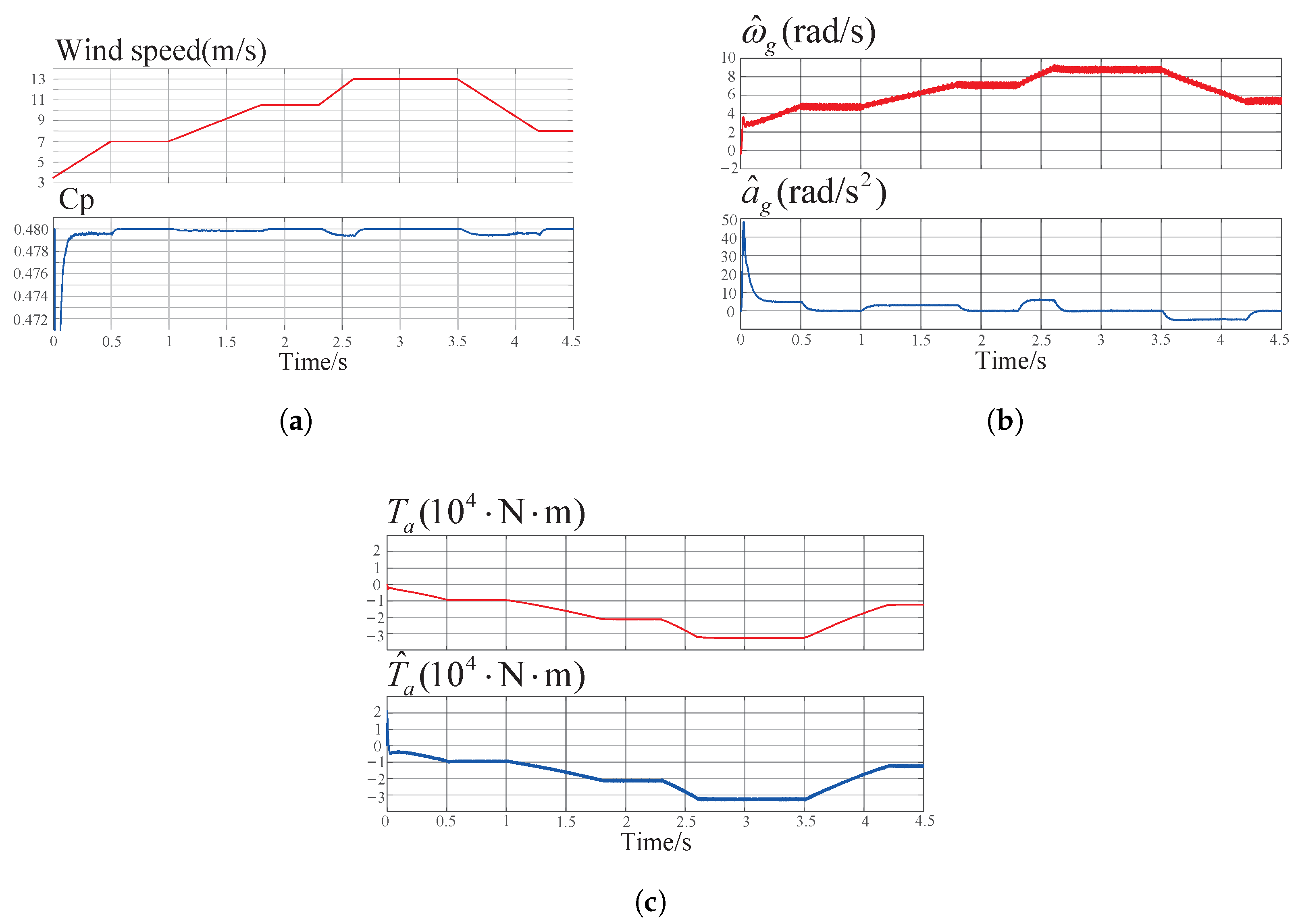
3. Numerical Simulation Results

For this section, simulations based on MATLAB/Simulink were performed to verify the acceleration-observer-based position and load torque estimation method. The simulation model is illustrated as in Figure 5. A 300 KW wind turbine was included, and the rated wind speed was 13 m/s. The radius of the wind turbine blade was 12 m and the air density was 1.2 kg/m3. The moment of inertia J g was set to 60 kg·m2, and the resistance R s , inductance L m , and pole pairs were chosen as 0.025 Ω , 3.6 mH, and 12, respectively. The sliding mode observer parameter was designed as h = 410 . To validate the effectiveness of the proposed estimation method, the simulations were conducted under three different wind variation cases, as summarized in Table 1. The corresponding simulation results are presented in three sets of figures below, each corresponding to one of the three cases. Each set includes the simulation environment and the estimated variables.
Case A: Figure 6 presents the simulation results for Case A. Figure 6a contains two subplots, with the upper one illustrating the variation of the wind speed reference, including its amplitude and change slope, while the other one shows the corresponding power coefficient ( C p ). It can be seen that C p derived from the blade model remained relatively stable around 0.48, which is the theoretical maximum value according to the Betz limit. Figure 6b shows the estimated mechanical angular speed and acceleration, both of which varied smoothly and closely followed the wind speed profile presented in Figure 6a. As shown in Figure 6c, the proposed method achieved zero-error estimation of the load torque under wind speed variations, with the estimated torque accurately tracking the actual load torque measured by the sensors. These results indicate that the proposed method performed effectively in Case A. In this case, the proposed estimation method exhibited high effectiveness and stability, confirming the validity of the approach.
Case B: Figure 7 demonstrates the simulation results for Case B. The variation of wind speed shown in Figure 7a exhibited continuous ramp-up and ramp-down, with more pronounced fluctuations compared to Case A. As a result, the power coefficient C p also showed more noticeable oscillations under this wind condition. Despite this, the proposed estimation method demonstrated strong performance in estimating mechanical angular speed, acceleration, and load torque, maintaining both a good dynamic and steady-state accuracy, as shown in Figure 7b,c.
Case C: Figure 8 shows the simulation results for Case C, where step changes in wind speed were introduced to simulate the most complex wind conditions, leading to even larger fluctuations in the power coefficient C p . From the response curves of the estimated mechanical angular speed, acceleration, and load torque in Figure 8b,c, it can be observed that despite the abrupt changes in wind speed, the estimated variables quickly stabilized, showing the effectiveness of the proposed estimation method.
Case D: Figure 9 presents the simulation results for Case D. A 10% variation of stator resistance and stator inductance of PMSG was introduced to test the parameter robustness of the proposed method. The wind speed profile and corresponding power coefficient C p are shown in Figure 9a. As illustrated in Figure 9b,c, which display the estimated mechanical angular speed, acceleration, and load torque, the proposed method demonstrated strong robustness in the presence of parameter uncertainties.
Case E: Figure 10 displays the simulation results for Case E. To simulate sensor measurement noise, white noise with the power of 10W was added to both the current and voltage signals. The wind speed profile and corresponding power coefficient C p are shown in Figure 10a. Figure 10b,c illustrate the estimated mechanical angular speed, acceleration, and load torque. The results demonstrate that the proposed method maintained strong robustness and estimation accuracy even in the presence of significant measurement noise.
The simulation results in the five cases shown in Figure 6, Figure 7, Figure 8, Figure 9 and Figure 10 demonstrate the excellent stability, responsiveness, accuracy, and robustness of the proposed acceleration-observer-based load torque estimation method. It was essential to the estimation to obtain the mechanical angular acceleration, where different wind speed variations effectively served as distinct input signals for the acceleration. The significant overshoot in both acceleration and estimated load torque at the beginning was attributable to the high starting torque required when the generator initiated operation. Additionally, the large electromagnetic torque contributed to this overshoot, as evident from (16), where T e plays a dominant role in calculating T ^ a . This is due to the relatively small angular speed and acceleration of wind turbine generators.
These simulation results verify the feasibility and reliability of the proposed estimation method under various wind conditions. The method consistently demonstrated an accurate and stable estimation performance, even in the event of abrupt changes in wind speed. This confirms its effectiveness in practical wind turbine control applications, particularly in environments where physical sensors are either unavailable or vulnerable to harsh operating conditions.

4. Conclusions

To ensure reliable operation of wind turbines in the event of position and torque sensor failures, this paper proposes an acceleration-observer-based position and load torque estimation method for wind turbines. The method has been theoretically proven to be stable and is capable of accurately estimating the rotor position, speed, and acceleration of the PMSG. This estimated information is then used to achieve fast and precise load torque estimation. Our numerical simulation results demonstrate that the proposed method exhibits excellent dynamics, accuracy, and robustness under various operating conditions.
The operational environment of wind turbines is becoming increasingly harsh and challenging, with high maintenance costs and greater difficulty in servicing. This necessitates the enhanced reliability of such turbines to reduce failure rates and lower maintenance costs, while also requiring the ability for fault-tolerant operation in the event of sensor failures. The proposed method addresses this need by maintaining excellent performance during position and torque sensors faults, representing an important first step toward fault-tolerant wind turbine control. Future work will focus on developing a complete fault-tolerant control strategy to ensure great performance during fault transitions.

Author Contributions

Conceptualization, Z.W., G.L. and Z.D.; writing—original draft preparation, Z.W. and X.W.; writing—review and editing, Z.W. and G.L.; visualization, Z.W.; supervision, N.R. and Z.D.; project administration, N.R. and Z.D.; funding acquisition, N.R. and Z.D. All authors have read and agreed to the published version of the manuscript.

Funding

This work was supported by the National Key Research and Development Program of China under Grant 2023YFB4203200.

Data Availability Statement

The original contributions made in this study are contained within the article. Any further questions can be addressed to the corresponding author.

Acknowledgments

Thank you for the support of Xidian University and Ming Yang Smart Energy Group Limited.

Conflicts of Interest

Author Na Ren was employed by the Ming Yang Smart Energy Group Limited. The remaining authors declare that the research was conducted in the absence of any commercial or financial relationships that could be construed as a potential conflict of interest.

Abbreviations

The following abbreviations are used in this manuscript:
SMOsliding mode observer
PMSGpermanent magnet synchronous generator
PLLphase-locked loop
LFloop filter

References

  1. Rahideh, A.; Korakianitis, T. Analytical magnetic field distribution of slotless brushless machines with inset permanent magnets. IEEE Trans. Magn. 2011, 47, 1763–1774. [Google Scholar] [CrossRef]
  2. Vicknair, D.; Tansey, M.; O’Brien, T. Measuring fossil fuel reserves: A simulation and review of the U.S. Securities and Exchange Commission approach. Resour. Policy 2022, 79, 103028. [Google Scholar] [CrossRef]
  3. Pastore, L.; Basso, G.; Ricciardi, G.; de Santoli, L. Synergies between Power-to-Heat and Power-to-Gas in renewable energy communities. Renew. Energy 2022, 198, 1383–1397. [Google Scholar] [CrossRef]
  4. Yue, N.; Yang, C.; Li, S. The Influence of Reduced Frequency on H-VAWT Aerodynamic Performance and Flow Field Near Blades. Energies 2024, 17, 4760. [Google Scholar] [CrossRef]
  5. Zhang, C.; Li, J.; Liu, S.; Hu, P.; Feng, J.; Ren, H.; Zhang, R.; Jia, J. Coordinated Frequency Modulation Control Strategy of Wind Power and Energy Storage Considering Mechanical Load Optimization. Energies 2024, 17, 3198. [Google Scholar] [CrossRef]
  6. Njiri, J.G.; Söffker, D. State-of-the-art in wind turbine control: Trends and challenges. Renew. Sustain. Energy Rev. 2016, 60, 377–393. [Google Scholar] [CrossRef]
  7. Pao, L.Y.; Johnson, K.E. Control of wind turbines. IEEE Control Syst. Mag. 2011, 31, 44–62. [Google Scholar]
  8. Jung, C.; Sander, L.; Schindler, D. Future global offshore wind energy under climate change and advanced wind turbine technology. Energy Convers. Manag. 2024, 321, 119075. [Google Scholar] [CrossRef]
  9. Salic, T.; Charpentier, J.F.; Benbouzid, M.; Le Boulluec, M. Control strategies for floating offshore wind turbine: Challenges and trends. Electronics 2019, 8, 1185. [Google Scholar] [CrossRef]
  10. Jonkman, J.M. Dynamics Modeling and Loads Analysis of an Offshore Floating Wind Turbine; University of Colorado at Boulder: Boulder, CO, USA, 2007. [Google Scholar]
  11. Pao, L.Y.; Johnson, K.E. A tutorial on the dynamics and control of wind turbines and wind farms. In Proceedings of the 2009 American Control Conference, St. Louis, MO, USA, 10–12 June 2009; pp. 2076–2089. [Google Scholar]
  12. van Engelen, T.G. Design Model and Load Reduction Assessment for Multi-Rotational Mode Individual Pitch Control (Higher Harmonics Control); Technical Report ECN-RX–06-068; Energy Research Centre of the Netherlands (ECN): Petten, The Netherlands, 2006; Available online: https://publicaties.ecn.nl/PdfFetch.aspx?nr=ECN-RX--06-068 (accessed on 16 March 2025).
  13. Selvam, K. Individual Pitch Control for Large Scale Wind Turbines: A Multivariable Control Approach; Technical Report ECN-E–07-053; Energy Research Centre of the Netherlands (ECN): Petten, The Netherlands, 2007; Available online: http://www.ecn.nl/docs/library/report/2007/e07053.pdf (accessed on 18 March 2025).
  14. Shah, K.A.; Meng, F.; Li, Y.; Nagamune, R.; Zhou, Y.; Ren, Z.; Jiang, Z. A synthesis of feasible control methods for floating offshore wind turbine system dynamics. Renew. Sustain. Energy Rev. 2021, 151, 111525. [Google Scholar] [CrossRef]
  15. Cooperman, A.; Martinez, M. Load monitoring for active control of wind turbines. Renew. Sustain. Energy Rev. 2015, 41, 189–201. [Google Scholar] [CrossRef]
  16. Liu, X.; Bo, L.; Luo, H. Dynamical measurement system for wind turbine fatigue load. Renew. Energy 2016, 86, 909–921. [Google Scholar] [CrossRef]
  17. Martinez, M.; Fernandez, D.; Reigosa, D.; Guerrero, J.M.; Briz, F. Wireless torque pulsations measurement system for PMSMs. IEEE Trans. Ind. Appl. 2020, 56, 6467–6476. [Google Scholar] [CrossRef]
  18. Gao, J.; Li, C.; Dai, L.; Huang, S.; Xu, W. A practical analytical expression and estimation for average torque of high saturation permanent magnet synchronous motor for special vehicles. IEEE Trans. Veh. Technol. 2022, 72, 357–366. [Google Scholar] [CrossRef]
  19. Mohamed, M.; Jemli, M.; Gossa, M.; Jemli, K. Doubly fed induction generator (DFIG) in wind turbine modeling and power flow control. In Proceedings of the 2004 IEEE International Conference on Industrial Technology, Hammamet, Tunisia, 8–10 December 2004; pp. 580–584. [Google Scholar]
  20. Cardenas, R.; Pena, R.; Proboste, J.; Asher, G.; Clare, J. MRAS observer for sensorless control of standalone doubly fed induction generators. IEEE Trans. Energy Convers. 2005, 20, 710–718. [Google Scholar] [CrossRef]
  21. Payam, A.; Jalalifar, M. Robust speed sensorless control of doubly-fed induction machine based on input-output feedback linearization control using a sliding-mode observer. In Proceedings of the 2006 International Conference on Power Electronic, Drives and Energy Systems, New Delhi, India, 12–15 December 2006; pp. 1–5. [Google Scholar]
  22. Dendouga, A.; Abdessemed, R.; Bendaas, M.; Chaiba, A. Decoupled active and reactive power control of a doubly-fed induction generator (DFIG). In Proceedings of the 2007 Mediterranean Conference on Control & Automation, Athens, Greece, 27–29 June 2007; pp. 1–5. [Google Scholar]
  23. Benlaloui, I.; Drid, S.; Chrifi-Alaoui, L.; Ouriagli, M. Implementation of a new MRAS speed sensorless vector control of induction machine. IEEE Trans. Energy Convers. 2014, 30, 588–595. [Google Scholar] [CrossRef]
  24. Thomsen, S.; Rothenhagen, K.; Fuchs, F. Online parameter identification methods for doubly fed induction generators. In Proceedings of the 2008 IEEE Power Electronics Specialists Conference, Rhodes, Greece, 15–19 June 2008; pp. 2735–2741. [Google Scholar]
  25. Taherzadeh, M.; Hamida, M.A.; Ghanes, M.; Koteich, M. A New Torque Observation Technique for a PMSM Considering Unknown Magnetic Conditions. IEEE Trans. Ind. Electron. 2021, 68, 1961–1971. [Google Scholar] [CrossRef]
  26. Tang, S.; Cao, Y.; Shi, T.; Yan, Y.; Xia, C. Online Estimation of Load Torque and Moment of Inertia Incorporating Extended Disturbance Observer with Trigger. IEEE Trans. Power Electron. 2024, 40, 5731–5742. [Google Scholar] [CrossRef]
Figure 1. Five distinct operation regions for wind turbines: S 1 , start-up region; S 2 , low wind speed region; S 3 , optimal tip–speed ratio region; S 4 , rated speed region; S 5 , constant power region.
Energies 18 02787 g001
Figure 2. General structure of acceleration-observer-based estimation method.
Energies 18 02787 g002
Figure 3. Block diagram of the proposed estimator based on type-3 PLL, with a second-order integrator connected in parallel to the conventional PI controller.
Energies 18 02787 g003
Figure 4. Small-signal model of loop filter for the type-3 PLL.
Energies 18 02787 g004
Figure 5. General structure of the simulation model for wind turbine system aiming to verify the acceleration-observer-based load torque estimation method.
Energies 18 02787 g005
Figure 6. Simulation results for Case A: (a) Wind speed reference and Cp. (b) Estimated mechanical angular speed and acceleration. (c) Estimated load torque with actual value for comparison.
Energies 18 02787 g006
Figure 7. Simulation results for Case B: (a) Wind speed variation and Cp. (b) Estimated mechanical angular speed and acceleration. (c) Estimated load torque with actual value for comparison.
Energies 18 02787 g007
Figure 8. Simulation results for Case C: (a) Wind speed variation and Cp. (b) Estimated mechanical angular speed and acceleration. (c) Estimated load torque with actual value for comparison.
Energies 18 02787 g008
Figure 9. Simulation results for Case D: (a) Wind speed variation and Cp. (b) Estimated mechanical angular speed and acceleration. (c) Estimated load torque with actual value for comparison.
Energies 18 02787 g009
Figure 10. Simulation results for Case E. (a) Wind speed variation and Cp. (b) Estimated mechanical angular speed and acceleration. (c) Estimated load torque with actual value for comparison.
Energies 18 02787 g010
Table 1. Simulation conditions.
CasesWind Conditions
Case AGradual staged increase or decrease of wind speed.
Case BContinuous ramp-up and ramp-down of wind speed.
Case CVariations with step changes of wind speed.
Case DGradual staged increase or decrease of wind speed
with 10% variation of stator resistance and stator inductance of PMSG.
Case EGradual staged increase or decrease of wind speed
with white noise in current and voltage signals
Disclaimer/Publisher’s Note: The statements, opinions and data contained in all publications are solely those of the individual author(s) and contributor(s) and not of MDPI and/or the editor(s). MDPI and/or the editor(s) disclaim responsibility for any injury to people or property resulting from any ideas, methods, instructions or products referred to in the content.

