Review

Non-Uniformities in Heat Exchangers: A Two-Decade Review of Causes, Effects, and Mitigation Strategies

1
Institute of Engineering Design & Technology (IEDT), Kyungpook National University, Daegu 41566, Republic of Korea
2
School of Mechanical Engineering, College of Engineering, Kyungpook National University, Daegu 41566, Republic of Korea
3
U.S.-Pakistan Center for Advanced Studies in Energy, National University of Sciences and Technology (NUST), H-12 Sector, Islamabad 44000, Pakistan
4
Department of Mechanical Engineering, University of Engineering and Technology, Peshawar 25000, Pakistan
*
Author to whom correspondence should be addressed.
Energies 2025, 18(11), 2751; https://doi.org/10.3390/en18112751
Submission received: 28 April 2025 / Revised: 20 May 2025 / Accepted: 23 May 2025 / Published: 26 May 2025

Abstract

:
While extensive research has focused on improving the efficiency and performance of heat exchangers (HXs), identifying the underlying causes of performance degradation remains equally important. Flow and temperature non-uniformities are among the most critical factors affecting performance, often reducing thermo-hydraulic efficiency by approximately 5–10%. These non-uniformities commonly manifest as thermal inconsistencies, airflow maldistribution, and uneven refrigerant distribution. Researchers have observed a notable performance degradation—up to 27%—due to flow maldistribution. Therefore, a clear understanding of their causes and effects is essential for developing effective mitigation strategies to enhance system performance. Despite the notable progress in this area, few studies have systematically classified the dominant non-uniformities associated with specific HX types. This article presents a two-decade review of the causes, impacts, and mitigation approaches related to non-uniformities across different HX configurations. The primary objective is to identify the most critical form of non-uniformity affecting performance in each category. This review specifically examines plate heat exchangers (PHXs), finned and tube heat exchangers (FTHXs), microchannel heat exchangers (MCHXs), and printed circuit heat exchangers (PCHXs). It also discusses mathematical models designed to account for non-uniformities in HXs. This article concludes by identifying key research gaps and outlining future directions to support the development of more reliable and energy-efficient HXs.

1. Introduction to Non-Uniformities in HXs

HXs often exhibit non-uniformities such as thermal inconsistencies, airflow maldistribution, and uneven refrigerant distribution. These irregularities degrade thermo-hydraulic performance, resulting in reduced HX efficiency. Although most HX designs assume uniform and steady inlet conditions for flow and temperature, this assumption does not hold under practical operating conditions. This problem is further exacerbated when non-uniformities originate at the inlet and persist throughout the exchanger. In addition to diminishing heat transfer capacity, these non-uniformities also increase energy consumption, emphasizing the need for effective control strategies.
Non-uniformities in heat exchangers primarily originate from two sources: geometric configuration and operating conditions. Maldistribution—whether in gross flow, between passages, or induced by manifolds—often stems from poor geometric design. It may also result from phase changes, variations in thermophysical properties, or degradation processes such as fouling and corrosion.
Non-uniformities in HXs often stem from design- and operation-related factors specific to each type. In PHXs, non-uniformities such as channel maldistribution and uneven refrigerant distribution typically result from improper header or distributor designs. FHXs are susceptible to airflow non-uniformities caused by improper fan installation, as well as uneven refrigerant distributions attributed to inefficient capillary systems. Meanwhile, in CHXs, such as mini/microchannel and printed circuit types, non-uniformities commonly stem from uneven refrigerant distribution and suboptimal header design. Similarly, in shell-and-tube configurations, poor placement of passes and baffles can disrupt flow uniformity. Despite these complexities, most current models and techniques still assume uniform flow, an assumption rarely valid in real-world applications. Addressing these deviations is therefore critical for advancing energy-efficient HX technologies.

1.1. Temperature Non-Uniformities

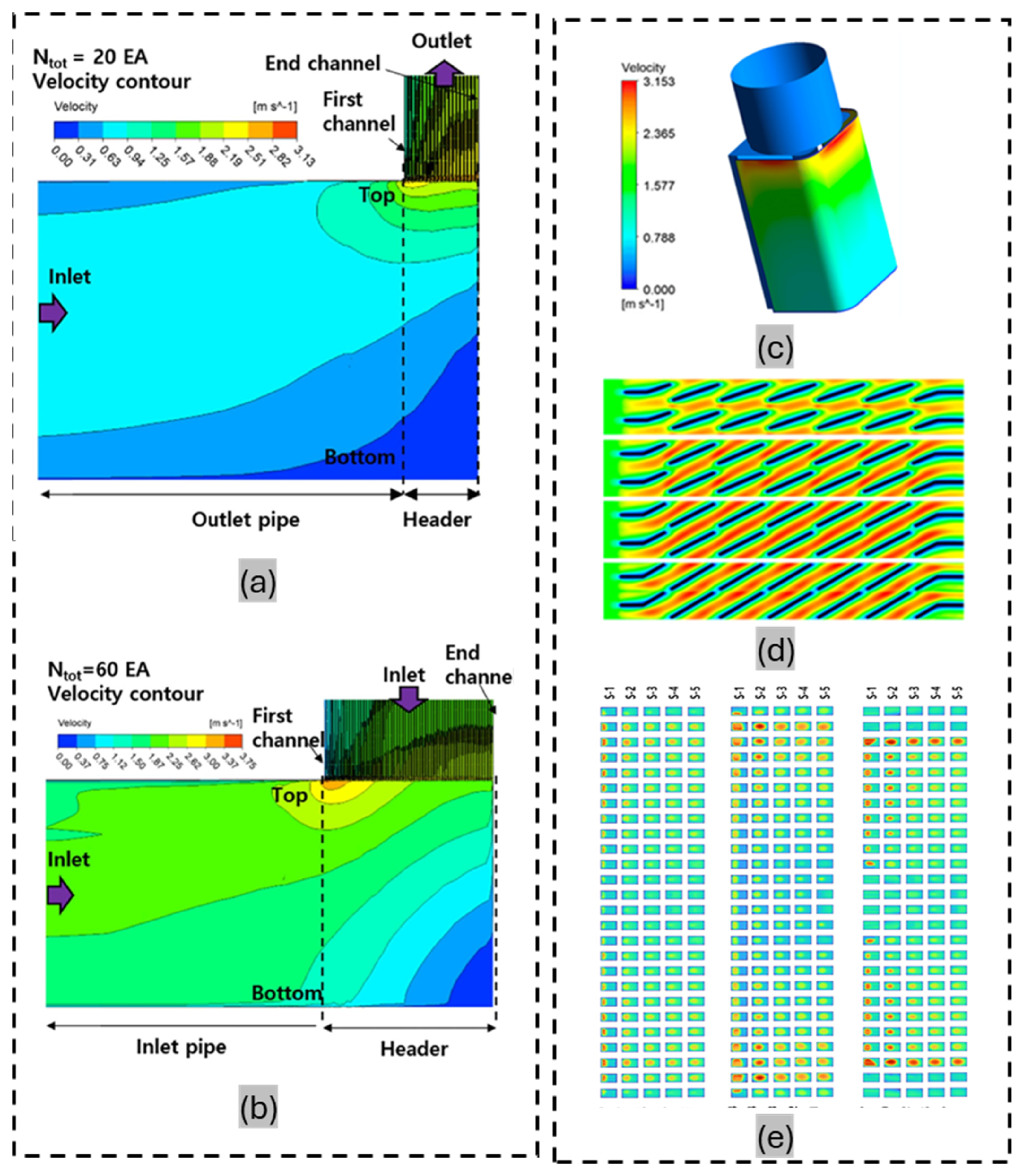
Temperature non-uniformities in HXs frequently arise from inadequate fluid mixing at the inlet, leading to considerable performance degradation. Flow fluctuations, along with design and operational factors such as flow maldistribution, fouling, and suboptimal geometry, can exacerbate these irregularities. In mixed-flow HXs, multiple fluid streams enter at different temperatures. Even in unmixed configurations, non-uniformities may emerge due to flow distribution issues. Here, fluid typically enters through the inlet header and passes through the distributor, often resulting in a non-uniform temperature profile. Although inlet temperatures are often assumed to be uniform for fluids entering the HX core along different passages, this assumption rarely holds in practice. Figure 1 presents the temperature contour distributions for various HX designs.
Temperature non-uniformities in PHXs typically arise from flow maldistribution in the header or inlet ports. Meanwhile, in FHXs, spatial temperature differences result from non-uniform airflow caused by the fan. Mini/microchannel HXs exhibit temperature imbalances owing to uneven refrigerant distribution within the channels. In shell-and-tube configurations, incorrect baffle installation and fouling are key contributors to thermal stress and reduced efficiency. In addition to these, other contributors include fatigue, blockages, thermal short-circuiting, manufacturing defects, and material failure. The resulting non-uniformities give rise to thermal strains, cold zones, and hotspots, ultimately reducing HX’s efficiency and service life. Such non-uniformities are not limited to HXs but have also been observed in thermoelectric generators for waste heat recovery, as noted by Lu et al. [1]. In some instances, intentionally introduced non-uniformities can improve the spatial alignment between the heat transfer coefficient and temperature difference, thereby enhancing thermal performance without substantial pressure losses, as demonstrated by Chu et al. [2]. In a recent study, Guo X et al. [3] highlights that while flow maldistribution often deteriorates performance, in some cases, it can enhance heat transfer if well matched with boundary conditions. The study categorizes maldistribution effects under adiabatic and non-adiabatic conditions and identifies discrepancies between experimental and real-world scenarios.

1.2. Flow Non-Uniformities

Flow non-uniformities typically manifest as either flow maldistribution or non-uniform airflow distribution. Although these terms are sometimes used interchangeably, they refer to distinct scenarios. Flow maldistribution commonly occurs in PHXs and CHXs equipped with headers or ports, where the refrigerant or air is distributed across multiple channels. The abrupt change in flow within these structures contributes to maldistribution. In contrast, non-uniform airflow distribution is typically observed in FHXs that depend on fan-driven external airflow. This type of non-uniformity is usually characterized by variations in face velocity profiles. Additional causes of airflow non-uniformities include turbulence, suboptimal inlet design, manufacturing flaws, fouling, and blockages.
Recent research has focused on optimizing airflow distribution and mitigating flow maldistribution to improve HX performance. For instance, Lee et al. [4] conducted computational fluid dynamics (CFD) simulations in psychrometric chambers to identify key factors influencing airflow uniformity. Their findings revealed that longer ducts and improved adjustment strategies can enhance uniformity, leading to better overall performance. Similarly, innovations such as rectangular header designs and arc-shaped baffles have been demonstrated to improve the performance of shell-and-tube HXs by minimizing flow non-uniformities [5,6]. Overall, these studies have offered valuable insights for improving HX designs across a wide range of applications [7,8].
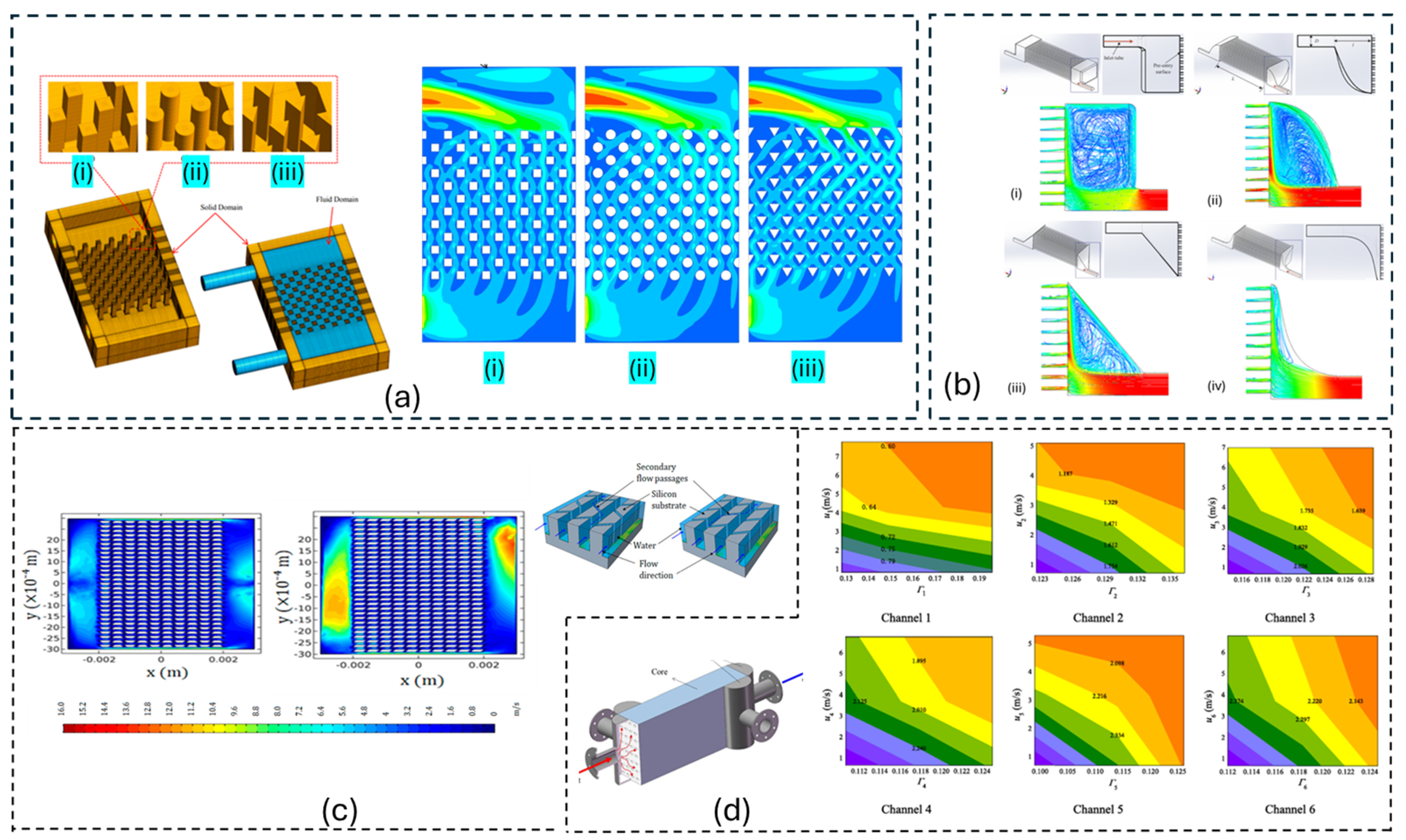
In a previous study, Aasi and Mishra [9] investigated parallel-flow HXs. They analyzed the effects of non-uniform airflow on vehicle radiators using the internal pressure balance approach and the effectiveness-number of transfer units (effectiveness-NTU) method. Their findings revealed that non-uniform airflow could enhance performance under certain conditions, particularly in HXs with smaller aspect ratios. They introduced the concept of “matching degree” to optimize alignment between internal fluid flow and external airflow. In 2020, Aasi and Mishra [10] studied three-fluid cross-flow CHXs and demonstrated that non-uniform flow delayed the onset of steady-state conditions, increased thermal stress, and dampened temperature oscillations. They further proved that axial dispersion had a greater influence than longitudinal conduction in turbulent regimes. In 2014, Gao et al. [11] demonstrated the dynamic behavior of PHXs in data centers under non-uniform airflow conditions. Their numerical study revealed that such non-uniformities significantly affect heat transfer rates, outlet temperatures, and energy efficiency, highlighting ways to address them during the design and optimization process for effective thermal management. Figure 2 presents airflow non-uniformity contours for PHXs, FTHXs, and MCHXs. It shows the air non-uniformity occurs in all these HXs. Figure 3a shows the non-uniformity in PCHXs of different shapes (square, circular, and triangular). Figure 3b shows flow in different header shapes. Figure 3c shows microchannel heat sink utilizing secondary flows in trapezoidal and parallel orientations; and Figure 3d shows predicted flow maldistribution in a PCHX.

1.3. Refrigerant Non-Uniformities

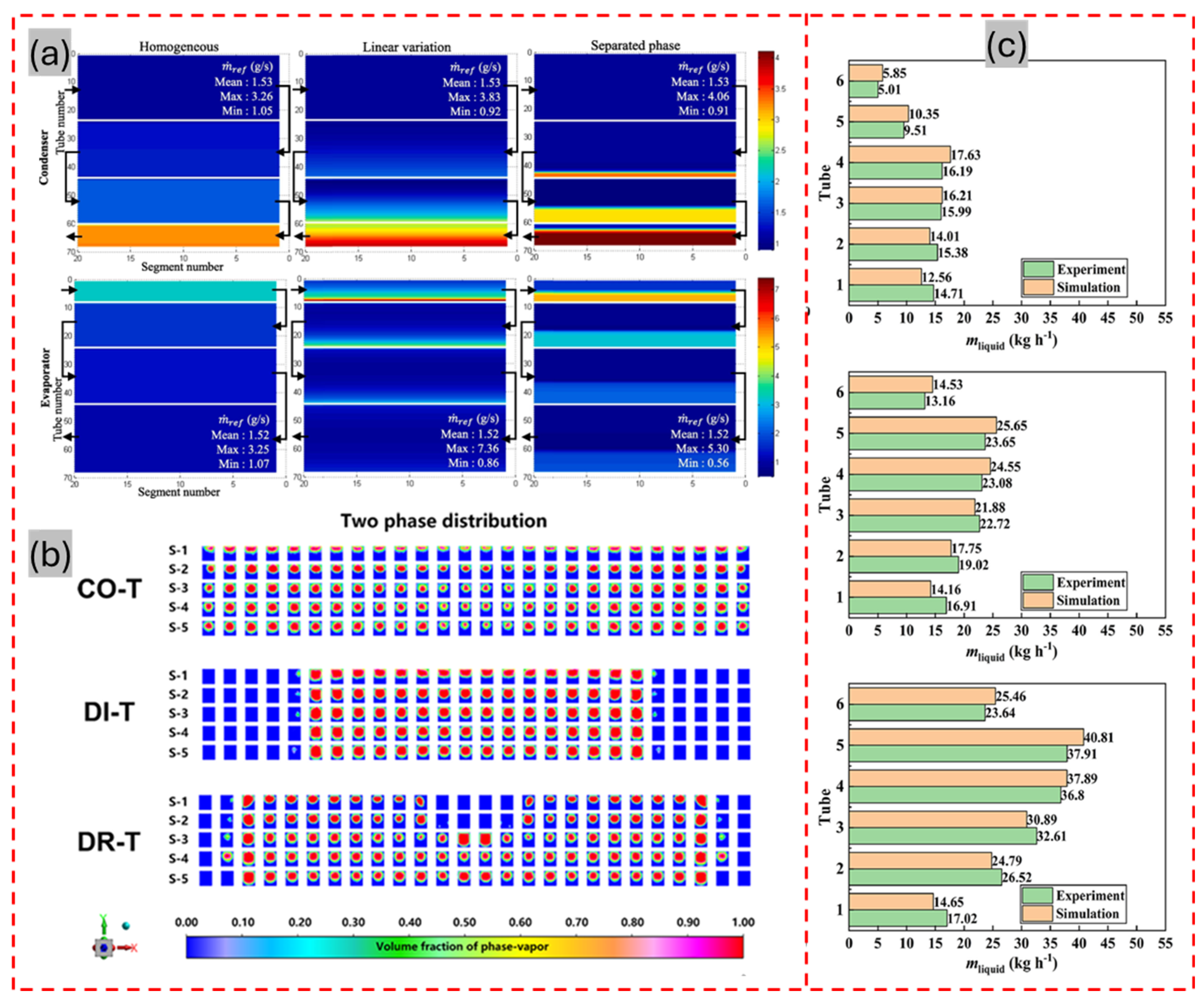
Refrigerant non-uniformities arise from maldistribution and phase change phenomena. These non-uniformities differ across HX types based on their operational and structural characteristics. For instance, in plate, mini/microchannel, and PCHXs, refrigerant maldistribution is typically caused by header geometry, distributor design, port arrangement, and uneven refrigerant distribution across channels. In FHXs, it results primarily from poorly designed refrigerant flow paths. Meanwhile, in shell-and-tube configurations, the refrigerant undergoes two-phase flow, which leads to phase separation and uneven distribution of liquid and vapor phases across the tubes. This condition reduces heat transfer efficiency and increases pressure drop. Strobel and Mortean [12] investigated three-dimensionally (3D)-PCHXs and reported that header geometry had a strong influence on fluid maldistribution, particularly at low flow rates. A pressure-based coefficient of variation method was introduced to quantify maldistribution, alongside a theoretical model for pressure drop prediction that yielded a 21% error margin. Li et al. [13] examined microchannel flat-tube HXs and optimized flow uniformity for two-phase R410A using three distributor configurations: column-type (CO-T), diffuser-type (DI-T), and drainage-type (DR-T) as shown in Figure 4b. Among these, the CO-T design achieved the best flow uniformity and heat transfer efficiency at low mass flux, while the DR-T design proved more effective at higher fluxes, underscoring the critical role of distributor design and flow uniformity in determining HX effectiveness. These insights reinforce the importance of mitigating refrigerant and airflow maldistribution to tap into the performance potential of compact HXs in diverse applications. Contours of refrigerant distribution in CHXs are depicted in Figure 4.

2. Impact of Non-Uniformities on PHX Performance: Causes and Mitigation Approaches

PHXs are widely used in chemical processing; petrochemical applications; heating, ventilation, and air conditioning (HVAC) system operation; and power generation. They feature narrow refrigerant flow paths and are sensitive to non-uniformities in refrigerant distribution, temperature, and airflow. Among these, uneven refrigerant distribution is the most critical, typically occurring in distributors, headers, ports, and channels.
Bobbili et al. [14] identified liquid flooding and flow maldistribution from ports to channels as major contributors to performance deterioration. They found that exit vapor quality, the port-to-channel diameter ratio, flow rate, and number of channels considerably influence refrigerant maldistribution. Zhang [15] and Habib et al. [16] expanded on this research by analyzing design parameters affecting flow uniformity. Specifically, Zhang [15] recommended a channel pitch of 2 mm to improve flow distribution. Tereda et al. [17] proposed selecting port sizes tailored to the specific plate arrangement as a simple and effective strategy for mitigating flow maldistribution in large HXs. Rao et al. [18] proposed optimizing the number of plates and highlighted key physical factors contributing to flow maldistribution. Dwivedi and Das [19] examined the effects of flow maldistribution on transient thermal behavior, emphasizing the interaction between airflow and temperature non-uniformities. In 2011, Hoffmann-Vocke et al. [20] examined how excessive hydraulic resistance linked to airflow contributes to maldistribution. They observed that performance degradation results from vertical flow spreading along the fins. Marchitto et al. [21] explored the influence of channel layout, inlet conditions, and header design on two-phase flow. Collectively, these studies underscore the importance of improved design strategies to mitigate performance losses associated with flow and temperature non-uniformities.
Refrigerant distributor design serves as a major contributor to flow maldistribution in PHXs. Zhang [15] demonstrated that flow uniformity is influenced by the distributor configuration, average flow speed, and channel hydraulic diameter. Under controlled conditions, an optimized distributor design with complementary fluid reduced flow non-uniformities by 57.4% and temperature variation by 13.7%. These researchers also examined how the Reynolds number correlates with flow distribution uniformity across different configurations. Their findings revealed that multi-hole distributors could be employed in air–water mixtures to improve flow distribution. Zhang et al. [22] introduces an innovative polymer manifold design—optimized using CFD and enabled by additive manufacturing—that effectively addresses flow maldistribution in heat exchangers. Featuring spiral baffles and repositioned inlet-facing tubes, the design achieves up to a 95% reduction in velocity deviation and significantly improves thermal and outlet temperature uniformity. The results highlight the promise of complex manifold geometries and advanced fabrication methods for enhancing heat exchanger performance.
Header design is another crucial factor influencing flow maldistribution. Yang et al. [23] incorporated punch baffles into a header. This addition improved both temperature and flow uniformity by minimizing the velocity difference across the channels. These effects were visually verified during the experiments. Habib et al. [16] observed that flow non-uniformity could be mitigated by adding a header to the tube, reducing nozzle diameter, and increasing the number of nozzles. They observed that the number of nozzles had a substantial effect on flow distribution, while nozzle diameter exerted only a minor influence. In 2015, Raul et al. [24] conducted several studies to identify alternative designs for mitigating flow maldistribution. Mahvi and Garimella [25] in 2017 built upon this research by analyzing air–water mixtures in various header geometries. They concluded that triangular headers provide more uniform flow distribution than rectangular ones, particularly at higher inlet mass fluxes and qualities. These findings underscore the importance of distributor and header geometry in optimizing flow distribution and enhancing the performance of P-fin HXs. To study flow maldistribution in parallel P-fin HXs, Yang et al. [23] developed a CFD model and used it to examine the effects of maldistribution on pressure drop and heat transfer effectiveness. Their results demonstrated that both punched baffles and quasi-S header configurations improve flow distribution, with the quasi-S header offering better results. Peng et al. [26] applied the particle swarm optimization algorithm to incorporate compensation effects under different maldistribution conditions. They achieved performance improvements ranging from 1.1% to 3.9%, with an associated error margin of approximately 4.19%. In a related effort, Shokouhmand and Hasanpour [27] employed the non-dominated sorting genetic algorithm-II to design an HX with reduced flow maldistribution. Overall, these studies demonstrated the effectiveness of optimization techniques, advanced configurations, and compensation strategies in addressing flow maldistribution and designing more efficient PHXs. In the same year, Peng et al. [28] proposed the use of splitter Ps to mitigate flow maldistribution and reduce pressure drop in multi-stream PHXs. This approach led to a 91.5% reduction in flow maldistribution and a 40.9% decrease in pressure drop relative to the conventional design. Thermal performance and flow uniformity were further enhanced by adjusting the splitter plates’ number, height, and angle in conjunction with header height. Overall, this innovative approach presented a practical solution for improving HX efficiency by balancing trade-offs in existing designs. Ham et al. [29] also examined optimal header and channel configurations using a CFD analysis to enhance flow uniformity and thermal performance. They observed that increasing the number of channels exacerbated flow non-uniformity near the inlet and outlet, leading to greater temperature variation and reduced heat transfer. Their results revealed that increasing the dimensionless pipe length beyond 10 substantially improved temperature (reducing the mean absolute temperature difference to 0.26–0.33 °C) and flow uniformity.
PHXs are typically classified as U-type or Z-type, and extensive studies have focused on the pressure reduction and flow maldistribution of both. According to these studies, Z-type arrangements tend to exhibit more severe maldistribution compared to their U-type counterparts. The possible reason behind this phenomenon is primary due to differences in flow path geometry, pressure distribution, and header design. In Z-type PHXs, the inlet and outlet are positioned on opposite sides, causing the fluid to traverse the entire length of HXs. On the other hand, U-type PHXs have both inlet and outlet on the same side. Hence, a pressure gradient along the flow path in Z-type PHXs is more prone to maldistribution than that of an even distribution of pressure across the channels of U-type PHXs. Moreover, in Z-type PHXs, a longer path is offered within the header as compared to the straightforward design in U-PHXs encountering varying resistance levels and results in unequal flow distribution [30,31,32,33].
For instance, Rao et al. [18] experimentally compared both exchanger configurations and reported greater maldistribution in Z-type exchangers. Srihari and Das [34] supported these findings, concluding that Z-type configurations exhibit greater maldistribution under both steady and transient operating conditions. In a related study, Shaji and Das [35] emphasized that in U-type configurations, separating the effects of flow maldistribution from back mixing is essential for independent parameter evaluation. Zhang [15] further explored Z-type configurations, specifically examining the influence of channel pitch diameter. Through experiments, they observed that smaller diameters (2 mm) improved flow uniformity, while larger diameters had the opposite effect. Further investigations by Siddiqui et al. [36] focused on flow distribution in U- and Z-type manifolds. Their results revealed that U-type manifolds maintained more uniform flow near the inlet, whereas Z-type manifolds exhibited better flow uniformity at the outlet but showed reduced uniformity at the inlet under higher flow rates. Further, particle image velocimetry (PIV) experiments validated the findings of numerical studies and demonstrated improvements in system efficiency through optimized manifold designs, especially for photovoltaic panel cooling. For instance, Qi et al. [37] used CFD modeling to assess the potential of U-, Z-, and L-type manifold configurations as Earth-to-air HXs (EAHEs). They reported that the L-type provided the most uniform airflow, while the U-type delivered better thermal performance. A key contribution of Qi et al.’s research was the development of practical design codes and guidelines for EAHE systems to enhance energy efficiency in greenhouse applications.
In PHXs, two-phase flow exhibits greater non-uniformity compared to single-phase flow [38]. Wang et al. [39] found that liquid-phase flow uniformity deteriorates as the Reynolds numbers of both the liquid (Reliq) and gas phases (Regas) decrease, while gas-phase uniformity improves with increasing Regas and deteriorates with decreasing Reliq. To address this issue, they proposed a perforated header design that improved two-phase flow uniformity and dryness distribution, reducing Sgas, Sliq, and Sdry by 4.7–35%, 5.4–44%, and 11.7–30%, respectively. In related research, Srihari and Das [34] examined the multi-pass arrangements in PHXs and observed equivalent heat transfer coefficients across all channels. They found that maldistribution, multi-pass flow paths, and back mixing notably affect dynamic performance characteristics, including response delay, asymptotic behavior, and time constants. Song et al. [40] conducted experimental and numerical studies on the influence of air velocity on heat transfer coefficients in two-row plate-FTHXs. Their findings informed the design and optimization of HXs, leading to improved thermal performance and reduced non-uniformities. In 2016, Peng et al. [41] explored the combined effects of passage arrangements and inlet flow maldistribution on multi-stream PHX performance, ultimately proposing an optimized configuration. Here, pass arrangement optimization was performed under varying inlet flow distributions. Further, the inlet manifold channel and plenum were modified to examine and optimize self-similarity heat sinks (SSHSs) while minimizing flow maldistribution, as proposed by Tang et al. [42]. W Li and Hrnjak [43] presented a mechanistic model to predict two-phase refrigerant distribution in brazed plate heat exchangers, focusing on non-uniformities caused by phase separation and header-induced pressure drops. The flow maldistribution in PHXs and its impact, analysis, and solutions are comprehensively addressed in a recent study by Kim et al. [44]. They highlighted the issue of flow maldistribution in PHXs, analyzing its adverse impact on heat transfer and pressure drop under both the single-phase and two-phase conditions. It explores contributing factors like header design and phase separation and evaluates mitigation strategies, including flow configuration and distributor optimization.

3. Impact of Non-Uniformities on FTHX Performance: Causes and Mitigation Strategies

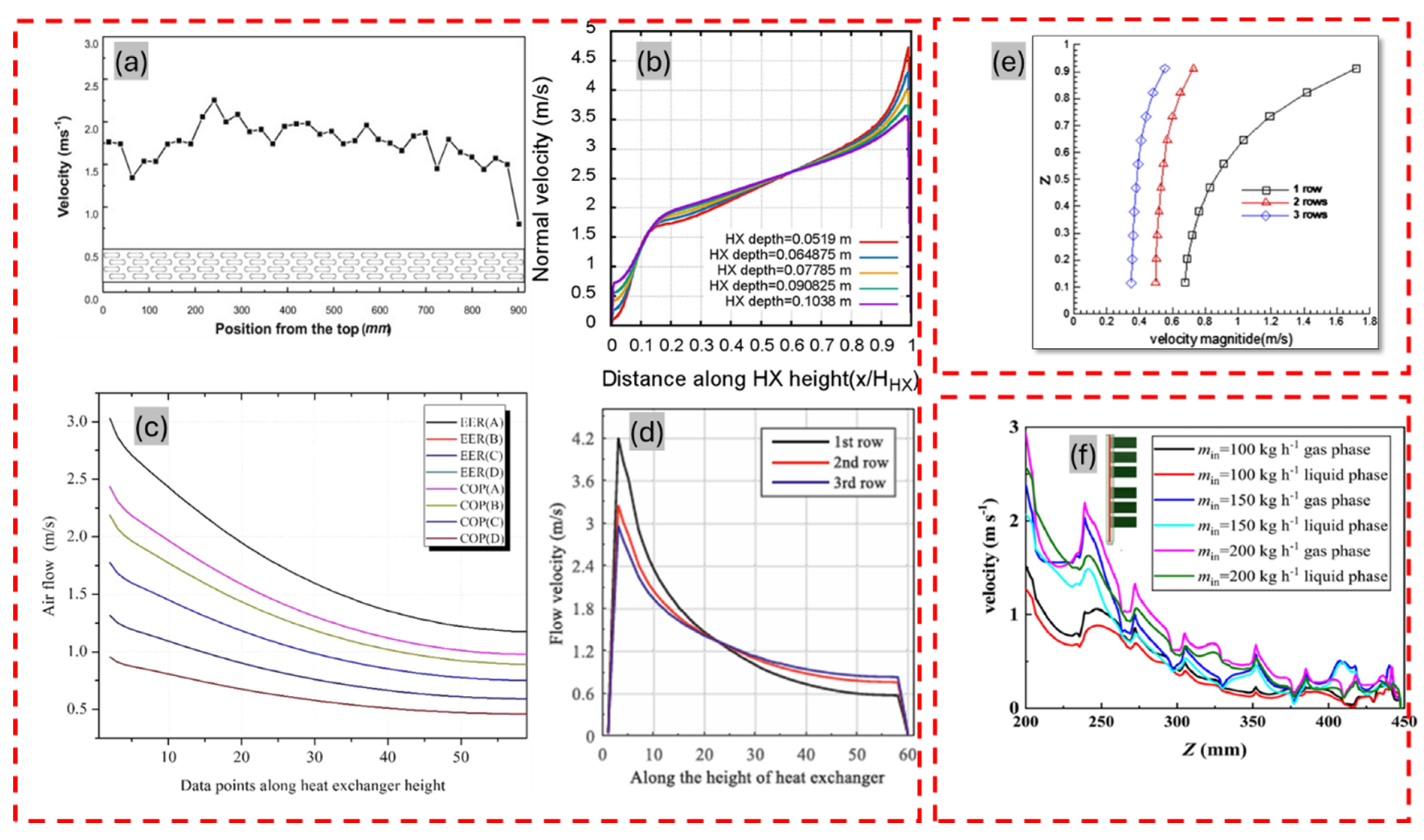
FTHXs are extensively utilized in HVAC systems, radiators, and applications across the aerospace, chemical, and petrochemical industries. A key challenge associated with these systems is the non-uniform distribution of airflow, which can considerably degrade heat transfer performance [45,46]. Consequently, numerous studies have investigated approaches to suppress these effects. Figure 5 presents airflow distribution patterns observed in various HX configurations. In all the Figure 5a–f the flow non-uniformity can be seen. The upper portion have higher airflow, and the lower part has lower airflow due to the fan position. Figure 5c shows eight face velocity profiles with two curves overlapping under different part load cooling and heating conditions.
Yashar and Domanski [47] as referenced by Choi et al. [48], studied the impact of non-uniform airflow distribution on HX performance. They proposed a mitigation strategy to reduce performance degradation caused by airflow non-uniformity. Subsequent studies focused on fin-and-tube HXs, with particular emphasis on refrigerant distribution.
In 2008, they extended their analysis to include three configurations: a single-slab coil oriented vertically, a single-slab coil angled at 65° to the duct wall, and a two-slab A-shaped coil with a 34° apex angle. Their subsequent investigation in 2009 revealed that condensation collection pans exacerbate airflow non-uniformity, increasing airflow by 20% in the upper slab and restricting it in certain regions owing to mounting brackets. They also observed that unevenly distributed water droplets on the condensing coils further impacted airflow uniformity. In 2010, they demonstrated that A-shaped evaporator coils, especially those equipped with condensation collection pans, exhibited substantial airflow non-uniformity, most notably in the lower sections under wet conditions. In 2014, they identified mounting brackets as one of the primary sources of airflow non-uniformity in louvered-fin HXs. Subsequently, in a series of studies conducted between 2008 and 2015, Yashar and Domanski examined the impact of non-uniform airflow distribution on evaporator performance and optimal refrigerant paths [47,49,50,51]. Notably, previous studies in this field primarily focused on airflow distribution, largely owing to the simplified nature of the underlying problem. However, these simplified assumptions could substantially impact the accuracy of the optimized outcomes [52]. Subsequent studies revealed that factors such as real-world operating conditions and suboptimal design choices can lead to inaccurate performance predictions when the airflow is non-uniform [53]. To address these complexities and optimize fin-and-tube HXs, Domanski and Yashar [54] developed an intelligent system for HX design (ISHED), an evolutionary algorithm-based tool embedded in the EVAP-COND simulation framework. Notably, the latest versions of EVAP-COND can evaluate HX performance and yield efficient design solutions. These tools can be applied reliably even under non-uniform airflow conditions to optimize refrigerant circuitry. Further research in this context examined the impact of flow distribution on refrigerant circuitry using a refined version of the ISHED. This enhanced module, based on a genetic algorithm, focused on minimizing maldistribution effects by optimizing refrigerant circuitry [54,55]. Yashar et al. [50,51] later applied this optimization approach to the evaporator of a rooftop air conditioning unit operating under non-uniform airflow conditions, demonstrating the tool’s effectiveness in producing optimized designs during the HX development stage.
In 2010, Lee et al. [56] achieved a 7.85% improvement in airflow uniformity by adjusting the coil angle in multi-coil HXs. Kennedy et al. [57] reported a marginal 0.5% performance improvement in air-cooled systems when the HX was inclined relative to the fan. To explore the combined effects of temperature and airflow maldistribution, Meng Chin [58] conducted a detailed study. Their results revealed that the shape index (SS) and statistical moments of the velocity distribution influenced thermal performance degradation. To mitigate the impact of maldistribution, higher SS values were recommended. In 2014, Bach et al. [59] evaluated active control and interleaved circuitry as strategies for improving refrigerant flow distribution. They found that active control mitigates performance losses more effectively than interleaved circuitry. However, when addressing non-uniform airflow in practice, cost and system reliability must also be considered, as interleaved circuitry may offer advantages in these areas despite its poorer performance.
Various methods have been used to evaluate the adverse effects of non-uniform airflow in FTHXs. For instance, Zhang et al. [60] investigated the impact of face velocity distribution on the performance of air-cooled condensers. They reported a 6% improvement in thermal performance by adjusting the airflow distribution to align with the face velocity profile. In 2016, Chen et al. [61] proposed a vertical configuration for air-cooled HXs. Compared to traditional designs, this configuration improved cooling efficiency and airflow rates under both calm and windy conditions. She et al. [62] studied airflow patterns in hybrid refrigeration systems and observed that both open-patterned and closed-patterned configurations could improve the coefficient of performance (COP) relative to conventional systems. Maximum improvements in COP—12.3% for the closed-pattern configuration and 9.8% for the open-pattern configuration—were achieved under varying climatic conditions. Tang et al. [42] examined the effects of airflow distribution on overflow channel design in the SSHSs of electronic cooling systems, focusing on variations in geometric parameters. Similarly, Deepakkumar et al. [63] investigated the air-side performance of FTHXs with multiple tube rows. They observed that at low inlet air velocities, an HX configuration using elliptical tubes followed by circular tubes outperformed one with only circular tubes. In contrast, at higher velocities, a mixed arrangement of circular and elliptical tubes yielded better performance than configurations using only elliptical tubes. Additional insights into non-uniform flows were provided by Ramadan et al. [64] through investigations on water–air HXs. Non-uniform air temperature was found to alter thermal performance by up to 5%. In contrast, non-uniform airflow velocities were observed to reduce overall system efficiency. To address temperature distribution issues, Ramadan et al. [64] proposed a control strategy incorporating thermocouples and air deflectors. In this design, cooler air was directed toward the lower section, whereas warmer air was directed toward the upper section. Consequently, 1.34 L of fuel was saved over a 3 h drive in an automotive cooling system. Collectively, these diverse investigations highlight the critical role of temperature and airflow non-uniformities, particularly in industrial cooling applications.
Recent studies have advanced the understanding of non-uniformities in HXs, highlighting their impact on performance and exploring potential solutions. In 2018, Lee et al. [4] developed a CFD-assisted model featuring a segmented control volume for air-to-refrigerant HXs. They used the effectiveness-NTU method and the Darcy–Forchheimer law to analyze airflow maldistribution. The developed model revealed that factors such as coil depth, apex angle, and fin type substantially affect flow uniformity, offering a useful tool for design optimization to minimize airflow non-uniformities. Validation using PIV revealed that airflow maldistribution could lead to a cooling capacity reduction of up to 23.54%. Similarly, Li et al. [65] optimized airflow non-uniformity in fin–tube HXs using an integer-permutation-based genetic algorithm, achieving a 4.8% improvement in COP and a 5.1% increase in cooling capacity. Additionally, in 2018, new evaluation methods based on non-dimensional parameters were introduced to assess the effects of maldistribution on HX performance. Building on this, Zhang et al. [66] categorized performance impacts into stable, deterioration, and rapid deterioration zones, presenting a systematic evaluation framework. Ishaque et al. [67] assessed the impact of HX design on heat pump performance under partial-load operating conditions. They analyzed face velocity profiles for cylindrical, trapezoidal, and rectangular residential outdoor HXs using CFD simulations. Their findings demonstrated that the cylindrical design was most effective in mitigating non-uniform airflow distribution and, thus, in improving overall system performance. Luo et al. [68] evaluated a novel C-type heat exchanger designed for duct air conditioners operating under non-uniform airflow. Compared to conventional A-type designs, the C-type offers up to 19.1% higher heat transfer capacity and improved outlet temperature uniformity by aligning with parabolic air velocity profiles, making it an effective solution against airflow maldistribution. These studies collectively underscore the critical need for innovative modeling, optimization, and experimental validation strategies to effectively address airflow maldistribution in HXs [46]. Figure 6 summarizes the impacts of non-uniformities on HX performance.

4. Impact of Non-Uniformities on MCHX and PCHX Performance: Causes and Mitigation Strategies

Several studies have investigated refrigerant flow maldistribution and airflow non-uniformity in printed circuit, mini-channel, and microchannel HXs. According to these studies, the aforementioned non-uniformities primarily arise from refrigerant maldistribution caused by header geometry and inlet configuration. Optimizing these components is essential for enhancing performance and identifying effective mitigation strategies. Dirker et al. [69] demonstrated that inlet type substantially influences heat transfer rates across different flow regimes in rectangular microchannels. They established empirical relationships for three inlet configurations to estimate the friction factor based on the Nusselt number. Two years later, Anbumeenakshi and Thansekhar [70] conducted a detailed analysis of flow maldistribution in an aluminum microchannel heat sink using deionized water as the coolant. They reported that a vertical inlet configuration resulted in lower flow maldistribution compared to an inline configuration. Ahmad et al. [71] investigated velocity non-uniformity in vertically downward channels, highlighting the complexity of heterogeneous flow distribution and its impact on performance. They found that using a moderate flow rate helped mitigate these effects. Wang et al. [60] investigated multiport flat-tube condensers with vertical headers and horizontal tubes. Their findings revealed that flow distribution and pressure drop are highly sensitive to aspect ratio, pass arrangement, and refrigerant mass flow rate, while heat capacity remains comparatively stable. Yang et al. [23] developed a mathematical model to evaluate flow maldistribution in multi-channel HXs. They observed that enhancing flow coordination between adjacent channels and optimizing header design can substantially reduce effectiveness deterioration and improve overall heat transfer performance. Mahvi and Garimella [25] investigated air–water mixture flows in microchannels with triangular and rectangular headers. They concluded that triangular headers offered superior flow uniformity due to favorable flow regime development, particularly at higher inlet mass fluxes and qualities. Guo et al. [72] investigated ALMT HXs with vertical headers and reported that refrigerant maldistribution driven by gravity and phase separation reduced thermal efficiency. To address this issue, they used optimized design configurations—specifically the decentered orifice plate and parallel multi-chamber—and achieved a notable reduction in flow distribution standard deviation, from 0.21 to 0.03, thereby substantially improving flow uniformity. Building on this, Ham et al. [73] examined variable refrigerant flow systems and highlighted the need for improved predictive models after observing pronounced gas-phase maldistribution at higher void fractions. Collectively, these and related studies underscore the importance of addressing non-uniform flow distribution in compact HXs.
Subsequent research has emphasized the critical influence of phase velocities, flow direction, and refrigerant distribution on the performance of compact HXs. For instance, Zhang et al. [74] experimentally compared the performance of an air conditioner equipped with a microchannel evaporator under upward and downward flow orientations. They found that the upward flow orientation resulted in a more favorable refrigerant distribution in the microchannel, underscoring the importance of flow direction in optimizing HX performance. In 2011, Saad et al. [75] highlighted the importance of accounting for phase velocity differences when designing offset strip fin HXs. Their results revealed that the superficial gas-phase velocity had a greater impact on performance than that of the liquid phase. Vist and Pettersen [76] first demonstrated the efficiency gains achievable through improved refrigerant distributions in compact HXs using R134a in 10 parallel tubes, recovering up to 4% of the lost cooling capacity. Building on this work, Lee et al. (2010) [56] found that adjusting the subtended angles between condenser coils effectively mitigated airflow maldistribution, leading to improved heat transfer and a 7.85% increase in airflow rate. Similarly, Ullah et al. [77] proposed optimal dimensions for a microchannel gas cooler designed for transcritical CO2 cooling in mobile applications, assuming a uniform airflow distribution. However, Song et al. [40] demonstrated that non-uniform air velocity in multi-circuit evaporators could reduce evaporator capacity by up to 7.78%. These findings underscore the importance of addressing air velocity discrepancies to ensure optimal performance in practical applications. Law et al. [78] emphasized the importance of geometric optimization in HXs, demonstrating that oblique angles between 10° and 50° enhanced heat transfer by promoting secondary flow mixing. However, this enhancement was accompanied by a notable increase in pressure drop, especially within the 10–30° range. They identified 50°-oblique-finned microchannels as a promising configuration for future parametric studies, offering a favorable balance between heat transfer enhancement and practical feasibility. More recently, Song et al. [79] investigated the combined effects of downward-flowing melted frost and uneven refrigerant distribution on defrosting performance using a specialized test facility. Their results demonstrated that these coupled effects adversely impacted system energy performance; however, defrosting efficiency improved markedly—from 40.5% to 47.9%—when the refrigerant distribution was optimized to a uniform state. Collectively, these studies underscore the importance of optimizing geometric design, airflow, and refrigerant distribution to mitigate non-uniformities and improve both the energy efficiency and operational performance of compact HXs.
Kim and Kim [80] investigated the complexities of refrigerant distribution in compact HXs. Their experimental study focused on a parallel-flow automotive condenser with 58 mini-channel tubes and four passes, using R-134a as the refrigerant. This study examined two-phase flow behavior, pressure drop, and thermal degradation caused by maldistribution. Although the inlet flow was largely uniform, two-phase jets formed liquid films and pooled at the bottom of the header in the downstream passes. Their findings revealed minimal thermal degradation (0.1–2.82%) attributed to maldistribution, with more pronounced effects at lower mass fluxes. In the same year, Lee et al. [81] numerically analyzed performance deterioration in multi-port mini-channel HXs due to refrigerant maldistribution in the header, using the M-Cube simulation tool. Three-phase distribution models—linear variation, homogeneous, and separated phase—were developed. The results revealed that condenser heat transfer decreased by up to 5% under worst-case maldistribution, while evaporator performance dropped by 63%, indicating greater sensitivity. In the evaporator, non-uniform phase distribution reduced heat transfer and decreased temperature differentials, as saturated gas occupied more tubes while contributing less to heat exchange. Cheng et al. [82] examined how non-uniform airflow affects the performance of a two-phase parallel-flow heat exchanger in data cabinet cooling. Both experimental and numerical results show that uneven air velocity and temperature cause localized overheating and reduced thermal uniformity. A validated two-phase model demonstrates how airflow asymmetry leads to premature overheating and irregular pressure drops. Their research suggested design improvements, such as multi-pass flow and fan speed control, to enhance cooling efficiency in practical applications. These findings underscore the importance of accounting for refrigerant maldistribution, particularly in high-efficiency systems such as air-conditioning units and automotive applications.
Recent studies on PCM-based heat sinks [83] and PCHEs [84] have focused on enhancing flow uniformity to improve thermal performance. For instance, a novel micro hyperbolic inlet header reduced flow non-uniformity by 46% and improved thermal performance by 39.5% compared to conventional parabolic headers, with longer core lengths further stabilizing the flow. This design also minimized localized thermal stresses and operational risks, improving overall system efficiency. Non-uniform flow and thermal distributions caused by geometry (channel diameter and bend angle) significantly affect pyrolysis efficiency and heat transfer. A 2.4 mm diameter and 30° bend angle provide optimal performance by balancing compactness, thermal cracking, and energy conversion, underscoring the importance of geometric design in mitigating non-uniformities in PCHEs [85]. In parallel, Ma et al. [86] developed a mathematical model considering real-world factors such as hydraulic losses and flow rates for flow maldistribution prediction in PCHEs. This model offered accurate maldistribution predictions and design guidelines for optimizing PCHEs.

5. Mathematical Modeling of Non-Uniformities

In one of the earliest studies in this field, Chiou [87] proposed a flow non-uniformity factor (Φ) to predict the deterioration in HX thermal performance caused by 2D flow non-uniformity. The degree of non-uniformity was defined as in Equation (1):
ϕ = m a c t u a l / m a v g   U D F ,
where mactual denotes the actual mass flow rate, and mavg UDF represents the average mass flow rate assuming uniformly distributed flow.
Chiou [87] also defined a thermal performance deterioration factor (τ) as
T = ε u n i f o r m   f l o w ε n o n u n i f o r m   f l o w ε u n i f o r m   f l o w .
Ranganayakulu et al. [88] studied flow maldistribution using a 2D finite element model (FEM). The HX face was modeled as a rectangular domain, and thermal resistance through the HX wall in the direction perpendicular to the fluid flow was neglected. Under a constant pressure gradient, cold or hot fluid flow was governed by the following equation:
2 W x 2 + 2 W y 2 = P μ z = a   c o n s t a n t .
Ratts [89] conducted a detailed numerical study on flow maldistribution in concentric tube HXs and introduced a fin efficiency model accounting for uneven temperature distribution. To enhance thermal uniformity, circumferential wires were installed within the concentric tubes; this approach proved effective at low Reynolds numbers but did not improve performance at higher flow rates. Ranganayakulu and Seetharamu [90] developed an FEM model to analyze the combined effects of non-uniform airflow, temperature distribution, and two-dimensional longitudinal heat conduction in a cross-flow P-fin HX. In a subsequent study, Ranganayakulu and Seetharamu [91] applied an FEM analysis to a cross-flow finned tube compact HX, investigating the influence of one-dimensional longitudinal wall conduction and non-uniform inlet flow and temperature profiles on both the hot and cold fluid sides. Roetzel and Ranong [92] evaluated the performance of parabolic and hyperbolic dispersion models for the steady-state operation of a shell-and-tube HX. They reported that the parabolic model performed well for HXs exhibiting flow maldistribution. The dimensionless dispersive flux was defined as
φ = q / λ T 1 T 2 L ,
where q* denotes the dispersive flux, λ* represents the dispersive conductivity, L signifies the nominal length of the HX, and T1 and T2 denote the fluid temperatures at the respective points.
In 1999, Lalot et al. [93] investigated overall flow maldistribution in an experimental electrically heated apparatus. They observed that reverse flow could occur due to poor inlet header design. They proposed a method to homogenize the flow distribution and derived an expression to calculate the ratio of the highest to the lowest velocity in the tubes. They demonstrated that total flow maldistribution reduced performance by approximately 7% in condensers and counter-flow HXs. A further reduction in effectiveness of up to 25% was observed for cross-flow exchangers. The ratio of extreme velocities, η, was expressed in terms of the pressure loss coefficient, ζ, as follows:
η = ζ 1 + ζ 2 m a x + ζ g ζ 1 + ζ 2 m i n + ζ g .
Instead of using a heuristic model for flow maldistribution, Sahoo and Roetzel [94] proposed the use of axial temperature profiles for shell-and-tube HXs. The resulting model was validated by comparing its Mach number and boundary conditions with those reported in previous studies. A hyperbolic model was proposed instead of the parabolic model, as it yielded better agreement with experimental results.
In 2003, Yuan [95] studied the impact of flow maldistribution in multi-fluid cross-flow HXs. Three flow maldistribution models were employed, all of which were found to influence HX performance. Non-uniformity was introduced using four different modes; one of these modes enhanced performance, while the remaining three led to performance deterioration. Performance improvement was observed in the mode characterized by high values of both the NTU and heat capacity ratios.
Rao and Das [96] investigated fluid flow maldistribution in PHXs, observing more severe maldistribution in Z-type PHXs than in U-type configurations. The maldistribution parameter (m2) was expressed as
m 2 = n A c A 2 1 ζ c ,
where n denotes the number of channels per fluid, and Ac and A represent the cross-sectional areas of the channel and port, respectively. Further, the pressure loss coefficient ζc was defined as
ζ c = 2 Δ P c h ρ U c .
For a detailed analysis of the port-to-channel flow distribution, the models developed by Bassiouny and Martin [97,98] may be referred to.
Liu et al. [99] proposed a graph-theory-based mathematical model to improve the efficiency of fin-and-tube HXs. This model utilized breadth-first and depth-first search algorithms to optimize the arrangement of refrigerant circuits and the distribution of refrigerant through them. They also accounted for heat conduction through the fins. Additionally, simulation time was reduced using iterative solution methods. In a related 3D numerical study, Mon and Gross [100] investigated an annular FTHX with two different arrangements. They systematically examined the effects of fin spacing on heat transfer, pressure drop, boundary layer development, and the formation of horseshoe vortices.
Srihari et al. [101] numerically analyzed flow maldistribution in a PHX with a single-pass configuration from port to channel. The governing equations were solved using the Laplace transformation, followed by numerical inversion. In this model, back mixing in the channels was represented by axial dispersion.
Bobbili et al. [14] reported that flow maldistribution also deteriorates thermal and hydraulic performance. This deterioration becomes more severe when phase change is involved, primarily owing to liquid flooding in two-phase flow. The effect of flow maldistribution from port to channel in PHXs was further examined by Dwivedi and Das [19], who proposed a numerical model to study the transient response of PHXs under various step flow conditions. The model was validated through comparison with experimental results.
Mishra et al. [102] investigated the effects of temperature and flow non-uniformity under different input conditions. They developed a beta flow maldistribution model to characterize flow non-uniformity. The governing energy conservation equation was expressed in terms of the maldistribution factor (α). The system responses were found to depend on the relative positions of the individual temperature streams and the location of the fluid-moving device, concerning temperature and flow non-uniformity, respectively. Later, Aasi and Mishra [9] proposed a flow distribution model for analyzing and quantifying non-uniformities at the inlet of HXs—factors critical to performance evaluation. The model begins with a 1D formulation wherein the flow distribution is represented by a function σ(x), defined over the spatial coordinate x. The parameters b and p control the flow profile: when b = p, the distribution is symmetrical; when b < p or b > p, the peak shifts toward one end, as described by Equations (8) and (9):
σ x = 1 β b , p x b 1 1 x p 1
β b , p = 0 1 x b 1 1 x p 1
To capture more realistic and complex scenarios, the model was extended to two dimensions, as described in Equations (10) and (11), by introducing the parameters b1, p1, b2, and p2 to represent non-uniformities along the width (x-direction) and height (y-direction) of the inlet cross-section. The total mass flow rate, G, is conserved, and the actual inlet flow distribution is expressed as ( f x , y = σ x , y G ) . To ensure computational feasibility, the flow distribution is discretized into grid cells, and a beta function is used to evaluate the non-uniformity at each point. This discretized approach enables the model to accommodate a wide range of flow profiles, making it suitable for simulating real-world HX inlet conditions and their effects on system performance.
σ x , y = 1 β b 1 , p 1 , b 2 , p 2 y b 1 1 1 y p 1 1 x b 2 1 1 x p 2 1
β b 1 , p 1 , b 2 , p 2 = 0 1 d y 0 1 y b 1 1 1 y p 1 1 x b 2 1 1 x p 2 1
Zhang [15] developed a CFD model to analyze flow distribution, wherein the plate–fin core was treated as a porous medium. A heat transfer model between the two streams was then established. The finite difference method was used to calculate heat exchange effectiveness and deterioration in thermal performance. This study primarily focused on the effect of channel pitch diameter on overall performance. Kandlikar et al. [103] proposed new numerical techniques for quantifying flow maldistribution based on pressure drop measurements at the inlet of each channel. These techniques were experimentally verified and implemented in both ex situ and in situ setups. They were deemed applicable to channels of various diameters.
Habib et al. [16] investigated flow maldistribution in air-cooled HXs using a 3D numerical model. They reported that nozzle diameter had only a minor effect on flow distribution. Pacio and Dorao [104] presented two models to study flow maldistribution in shell-and-tube evaporators by analyzing the geometry in terms of radial layers. In the first model, no interaction occurred between channels. In the second model, an equal pressure drop was imposed across all channels; thus, performance relied on the number of channels. The first model was reported to predict unrealistic pressure drops at the outlet, whereas the second model yielded more accurate results. Shaji and Das [35] proposed a computational technique based on the axial dispersion model. One of the objectives of their study was to distinguish between non-uniformities caused by fluid entry from the port to the channel and those arising from back mixing.
Kærn et al. [105] developed a numerical model to account for the capacity and COP degradation caused by two-phase flow maldistribution in fin-and-tube HXs. To simplify the analysis, straight tubes were used in place of the complex refrigerant circuitry typically found in such HXs. In a subsequent study, Kærn et al. [106] numerically investigated the thermal performance deterioration of fin-and-tube HXs resulting from the maldistribution of both refrigerant and air flow. Their results indicated that non-uniform phase distribution and uneven air flow were the primary contributors to performance degradation, while feeder tube bending had a relatively minor effect. Chin and Raghavan [107] developed a mathematical model based on a Taylor series expansion. They concluded that the mean and standard deviation of the flow distribution had a considerable impact on thermal performance, while skewness had a lesser effect, and kurtosis showed no meaningful influence. In a related study, Chin and Raghavan [108] quantitatively analyzed the impact of the statistical moments of the probability density function for an air flow maldistribution profile on the thermal performance of a fin-and-tube HX. Correlation equations were proposed to predict the effect of flow maldistribution on wavy fin performance.
Hsieh and Jang [109] conducted a comprehensive numerical study to investigate the effects of design parameters on the heat transfer and flow friction characteristics of an HX with louvered fins. Additionally, the design parameters of louvered FTHXs were optimized using the Taguchi method. Saad et al. [110] performed CFD simulations to analyze pressure drop behavior. Similarly, Mao et al. [111] examined the flow structure in two dimensions to characterize air velocity profiles and assess the impact of air flow maldistribution on heat transfer and pressure drop. Their study demonstrated that air flow non-uniformities influence condensation capacity, refrigerant pressure drop, and theoretical fan power consumption. Yashar et al. [50] investigated the effect of approach air distribution at the inlet of an HX using both experimental and numerical methods. A CFD model based on a momentum resistance approach was developed and experimentally validated. Vocale et al. [112] examined the influence of outdoor air temperature and relative humidity on the performance of an air-source heat pump under reverse-cycle defrosting conditions. Their findings indicated that this influence becomes less notable when evaluating seasonal heat pump performance. The maximum reduction in seasonal COP was reported to be less than 13% across all cases. Kumar et al. [113] conducted 3D numerical investigations on an air-cooled condenser. They compared the results of 2D and 3D simulations in terms of the Nusselt number and concluded that 3D simulations are essential to accurately capture natural convection flow phenomena, particularly in the presence of cylinder–cavity interactions. In a separate numerical study, Butler and Grimes [114] developed a mathematical model to predict condenser design and performance. They found that the most effective approach for assessing wind effects on condenser performance was to evaluate specific installation sites and optimize both performance and geometry based on historical local ambient wind conditions.
Bach et al. [59] analyzed the penalty associated with refrigerant flow maldistribution by calculating the effectiveness-NTU of an ACHP. The evaporator capacity was expressed in normalized form to quantify the impact of maldistribution, as follows:
Q n o r m = Q x % M D , t y p e / Q 0 % M D , s t a n d a r d
where Qnorm is the normalized capacity, Qx%MD,type is the capacity of a specific evaporator type under x% maldistribution, and Q0%MD,standard is the capacity under uniform distribution (i.e., with no applied maldistribution).
Niu et al. [115] conducted a comprehensive performance analysis and developed a regression model to predict the cooling capacity of EAHEs. They first established a numerical model to simulate EAHE performance, from which they derived regression equations for predicting cooling capacity.
In a numerical analysis, Łopata and Ocłoń [116] studied the flow around a bundle of externally finned elliptical tubes. They developed an algorithm to analyze variations in flue-gas temperature and the local heat transfer coefficient from the gas to the tube wall. Wang et al. [117] proposed a numerical model to predict the effects of condenser aspect ratio, pass arrangement (including pass number and the number of tubes per pass), and refrigerant mass flow rate on flow distribution, heat transfer, and refrigerant-side pressure drop. Yan et al. [118] developed a physics-based dynamic model of a three-evaporator air conditioning system. The model explicitly accounted for both sensible and latent heat balances on the airside of all indoor units.
In another study, Datta et al. [119] conducted both physical and numerical investigations to assess the thermal–hydraulic behavior of a condenser in a typical automotive air conditioning system under intake air maldistribution. A specialized simulation tool, CoilDesigner, was used to model heat transfer and fluid dynamics in the micro-tube, air-to-refrigerant, crossflow condenser with multiple channels. The simulation results showed that transport parameters were affected by a representative blockage. Lee and Jeong [120] numerically investigated the variations in heat transfer performance in condensers caused by non-uniform air flow distribution. The study was conducted under various refrigerant circuit configurations and air flow conditions. Their results showed that heat transfer capacity decreased depending on both the air flow rate and the specific refrigerant circuit arrangement. In a more recent study, Wang et al. [121] examined four factors influencing flow distribution in multi-circuit evaporators with distributors. Through a CFD analysis, they demonstrated that a proper feeder tube length configuration can compensate for the effects of air maldistribution. Yang et al. [23] developed a numerical model to evaluate the impact of non-uniform flow in multichannel HXs. Their findings indicated that achieving good synergy between the flow rates of hot and cold fluids in adjacent sub-exchangers can effectively reduce the deterioration in thermal effectiveness. Additionally, the overall HX efficiency was improved using optimized header configurations.
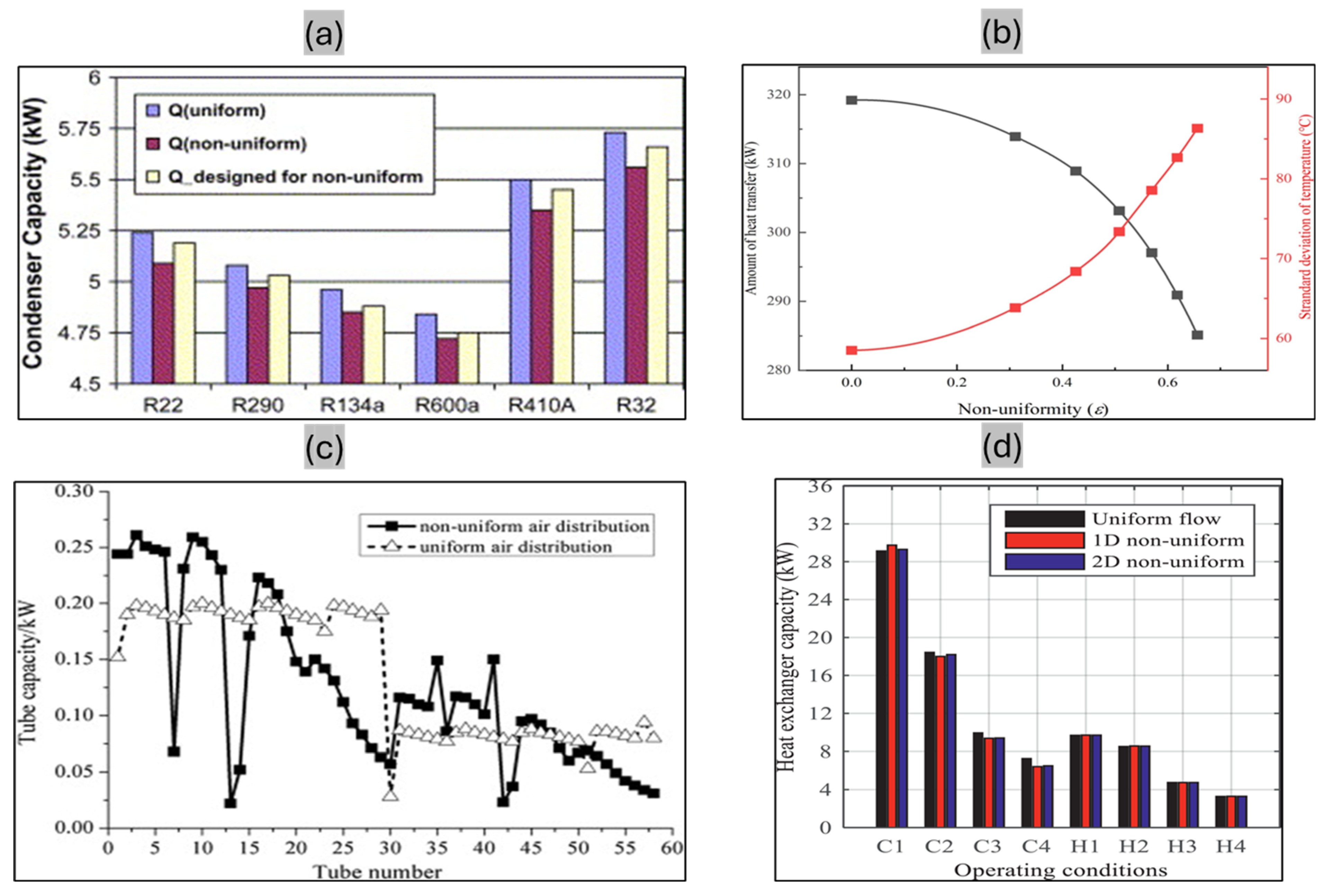
Recently, Li et al. [122] investigated the impact of inlet flow maldistribution on heat transfer and temperature fields in P-fin HXs. They introduced two key parameters—flow distribution offset (ξ) and non-uniformity (ε)—both of which had a substantial influence on heat transfer efficiency and temperature uniformity. Using a two-dimensional flow distribution model, their study showed that increasing ε led to reduced heat transfer and poorer temperature uniformity. Optimal performance was achieved at ξ = −0.67, while a ξ value of −1 resulted in a 6.4% decrease in heat transfer. These findings underscore the adverse effects of flow maldistribution, particularly under large temperature differences, with visual data illustrating the relationship between non-uniform flow and key performance metrics. Li et al. [123] presented a novel mathematical model to evaluate the impact of flow maldistribution on crossflow corrugated PHXs, integrating heat transfer and hydraulic models for a comprehensive analysis. Focusing on crossflow systems, their study revealed a 10–30% reduction in effectiveness due to gas flow maldistribution when the inlet gas Reynolds number ranged from 1100 to 2700. Table 1 summarizes the numerical studies and their modeling approaches in literature.

6. Summary and Future Directions

The energy-efficient design of HXs and their associated systems remains a key area of focus for researchers worldwide. One of the primary challenges in this domain is managing flow non-uniformities, which substantially affect overall system performance. Both manufacturers and end users increasingly demand high-efficiency HXs to promote energy savings and economic sustainability. However, the maldistribution of air, refrigerant mass flow, and the resulting non-uniform temperature profiles across HXs can severely diminish their effectiveness. Recent studies highlight that air velocity maldistribution alone can decrease heat transfer effectiveness by up to 27%, while optimized distributor geometries in plate evaporators can improve thermal performance by over 33%. In microscale and compact heat exchangers, non-uniform flow fields critically affect temperature distribution and species transport, especially under chemically reactive conditions. These findings underscore the necessity of integrated design approaches—combining geometry optimization, CFD analysis, and boundary-specific strategies—to minimize non-uniformities and enhance overall heat exchanger effectiveness.
This study presents a comprehensive overview of recent advancements aimed at minimizing non-uniformities in HXs, with particular attention to the dimensionless design parameters commonly employed in these studies. It examines the underlying causes of flow and temperature non-uniformities and discusses both experimental and numerical approaches developed to mitigate these effects. Numerical modeling, in particular, has proven to be a powerful tool for understanding fundamental design behavior and improving HX performance by enabling targeted modifications to system components.
The conventional design process for HXs is labor-intensive, often requiring thousands of iterative steps to achieve optimal performance. To address this challenge, many researchers have employed numerical techniques to model air and refrigerant flow. CFD has been widely used to predict flow profiles under various operating conditions and design configurations. Numerous commercial and academic software tools have been developed to support these efforts. However, the common assumption of uniform refrigerant or air distribution limits their accuracy in real-world scenarios. Consequently, the design and optimization of HXs under non-uniform conditions have emerged as a promising approach to enhance performance.
By integrating these modeling strategies, researchers and engineers can develop innovative solutions to mitigate non-uniformities, thereby improving the efficiency and sustainability of HXs. These findings highlight the critical importance of minimizing non-uniformities to optimize system performance in applications such as HVAC systems, power generation, and refrigeration. Future developments in emerging technologies and optimization strategies must account for realistic non-uniformity scenarios to advance the design and operation of next-generation HXs and energy systems.

Funding

This research received no external funding.

Informed Consent Statement

During the preparation of this work, the authors used ChatGPT (based on GPT-4-turbo) via OpenAI’s ChatGPT platform to improve the readability and language in a few parts of the manuscript. After using this tool/service, the authors reviewed and edited the content as needed and take full responsibility for the content of the publication.

Data Availability Statement

The data will be made available on request.

Acknowledgments

This work was partly supported by the Korea Institute of Energy Technology Evaluation and Planning (KETEP) grant funded by the Korea government (MOTIE) (project number: RS-2024-00421963).

Conflicts of Interest

The authors declare that they have no known competing financial interests or personal relationships that could have appeared to influence the work reported in this paper.

Abbreviations

HXheat exchanger
PHXplate heat exchanger
FTHXfinned and tube heat exchanger
MCHXmicrochannel heat exchanger
CHXcompact heat exchanger
PCHXprinted circuit heat exchanger

References

  1. Lu, X.; Yu, X.; Qu, Z.; Wang, Q.; Ma, T. Experimental investigation on thermoelectric generator with non-uniform hot-side heat exchanger for waste heat recovery. Energy Convers. Manag. 2017, 150, 403–414. [Google Scholar] [CrossRef]
  2. Chu, W.-X.; Bennett, K.; Cheng, J.; Chen, Y.-t.; Wang, Q.-w. Numerical study on a novel hyperbolic inlet header in straight-channel printed circuit heat exchanger. Appl. Therm. Eng. 2019, 146, 805–814. [Google Scholar] [CrossRef]
  3. Guo, X.; Li, Z.; Zhai, Y.; Wang, H. Flow maldistribution and its effect on the thermal performance of miniaturized devices: A perspective from thermal boundary condition. Energy Rev. 2024, 3, 100098. [Google Scholar] [CrossRef]
  4. Shao, H.; Zhang, M.; Zhao, Q.; Wang, Y.; Liang, Z. Study of improvements on flow maldistribution of double tube-passes shell-and-tube heat exchanger with rectangular header. Appl. Therm. Eng. 2018, 144, 106–116. [Google Scholar] [CrossRef]
  5. Menni, Y.; Chamkha, A.J.; Azzi, A.; Zidani, C.; Benyoucef, B. Study of air flow around flat and arc-shaped baffles in shell-and-tube heat exchangers. Math. Model. Eng. Probl. 2019, 6, 77–84. [Google Scholar] [CrossRef]
  6. Talebizadehsardari, P.; Mohammed, H.I.; Mahdi, J.M.; Gillott, M.; Walker, G.S.; Grant, D.; Giddings, D. Effect of airflow channel arrangement on the discharge of a composite metal foam-phase change material heat exchanger. Int. J. Energy Res. 2021, 45, 2593–2609. [Google Scholar] [CrossRef]
  7. Bishnoi, R.; Aharwal, K.R. Experimental evaluation of cooling characteristic, airflow distribution and mass transfer in a cold store. J. Food Process Eng. 2021, 44, e13609. [Google Scholar] [CrossRef]
  8. Zhao, L.; Wang, B.; Wang, J.; Zhu, Z.; Li, T.; Guo, B.; Zhang, J.; Zhang, H.; Yang, Z. Effect of non-uniform airflow on the performance of a parallel-flow heat exchanger considering internal fluid distribution—Simulation studies and its experimental validation. Appl. Therm. Eng. 2020, 180, 115685. [Google Scholar] [CrossRef]
  9. Aasi, H.K.; Mishra, M. Influence of flow non-uniformity on the dynamic behaviour of three-fluid cross-flow compact heat exchanger. Int. J. Therm. Sci. 2020, 149, 106177. [Google Scholar] [CrossRef]
  10. Gao, T.; Geer, J.; Sammakia, B. Nonuniform temperature boundary condition effects on data center cross flow heat exchanger dynamic performance. Int. J. Heat. Mass. Transf. 2014, 79, 1048–1058. [Google Scholar] [CrossRef]
  11. Strobel, M.; Mortean, M.V.V. Pressure drop and fluid maldistribution analysis of a compact heat exchanger manufactured by 3D printing. Int. J. Therm. Sci. 2022, 172, 107331. [Google Scholar] [CrossRef]
  12. Li, B.; Hou, J.; Xu, K.; Gao, Q.; Zeng, M.; Wang, Q. Optimal designs for flow uniformity at inlet of microchannel flat tube heat exchanger. Appl. Therm. Eng. 2023, 226, 120300. [Google Scholar] [CrossRef]
  13. Zhang, Y.; Han, W.; Shuai, W.; Song, X.; Shi, J.; Chen, J. Experimental and simulation study on the distributor design in plate evaporators. Int. J. Refrig. 2022, 143, 126–137. [Google Scholar] [CrossRef]
  14. Bobbili, P.R.; Sunden, B.; Das, S.K. Thermal analysis of plate condensers in presence of flow maldistribution. Int. J. Heat. Mass. Transf. 2006, 49, 4966–4977. [Google Scholar] [CrossRef]
  15. Zhang, L.Z. Flow maldistribution and thermal performance deterioration in a cross-flow air to air heat exchanger with plate-fin cores. Int. J. Heat. Mass. Transf. 2009, 52, 4500–4509. [Google Scholar] [CrossRef]
  16. Habib, M.A.; Ben-Mansour, R.; Said, S.A.M.; Al-Qahtani, M.S.; Al-Bagawi, J.J.; Al-Mansour, K.M. Evaluation of flow maldistribution in air-cooled heat exchangers. Comput. Fluids 2009, 38, 677–690. [Google Scholar] [CrossRef]
  17. Tereda, F.A.; Srihari, N.; Sunden, B.; Das, S.K. Experimental Investigation on Port-to-Channel Flow Maldistribution in Plate Heat Exchangers. Heat. Transf. Eng. 2007, 28, 435–443. [Google Scholar] [CrossRef]
  18. Rao, B.P.; Sunden, B.; Das, S.K. An Experimental and Theoretical Investigation of the Effect of Flow Maldistribution on the Thermal Performance of Plate Heat Exchangers. J. Heat. Transf. 2005, 127, 332. [Google Scholar] [CrossRef]
  19. Dwivedi, A.K.; Das, S.K. Dynamics of plate heat exchangers subject to flow variations. Int. J. Heat. Mass. Transf. 2007, 50, 2733–2743. [Google Scholar] [CrossRef]
  20. Hoffmann-Vocke, J.; Neale, J.; Walmsley, M. The effect of inlet conditions on the air side hydraulic resistance and flow maldistribution in industrial air heaters. Int. J. Heat. Fluid Flow. 2011, 32, 834–845. [Google Scholar] [CrossRef]
  21. Marchitto, A.; Fossa, M.; Guglielmini, G. The effect of the flow direction inside the header on two-phase flow distribution in parallel vertical channels. Appl. Therm. Eng. 2012, 36, 245–251. [Google Scholar] [CrossRef]
  22. Zhang, M.; Yang, C.M.; Li, K.; Nawaz, K. Reducing the Flow Maldistribution in Heat Exchangers through a Novel Polymer Manifold: Numerical Evaluation. Energies 2023, 16, 7120. [Google Scholar] [CrossRef]
  23. Yang, H.; Wen, J.; Gu, X.; Liu, Y.; Wang, S.; Cai, W.; Li, Y. A mathematical model for flow maldistribution study in a parallel plate-fin heat exchanger. Appl. Therm. Eng. 2017, 121, 462–472. [Google Scholar] [CrossRef]
  24. Raul, A.; Bhasme, B.N.; Maurya, R.S. A Numerical Investigation of Fluid Flow Maldistribution in Inlet Header Configuration of Plate Fin Heat Exchanger. Energy Procedia 2015, 90, 267–275. [Google Scholar] [CrossRef]
  25. Mahvi, A.J.; Garimella, S. Visualization of flow distribution in rectangular and triangular header geometries. Int. J. Refrig. 2017, 76, 170–183. [Google Scholar] [CrossRef]
  26. Peng, X.; Qiu, C.; Li, J.; Jiang, S. Thermal Compensation Effect of Passage Arrangement Design for Inlet Flow Maldistribution in Multiple-Stream Plate-Fin Heat Exchanger. Heat. Transf. Eng. 2019, 40, 1239–1248. [Google Scholar] [CrossRef]
  27. Shokouhmand, H.; Hasanpour, M. Effect of flow maldistribution on the optimal design of plate heat exchanger using constrained multi objective genetic algorithm. Case Stud. Therm. Eng. 2020, 18, 100570. [Google Scholar] [CrossRef]
  28. Peng, X.; Li, D.; Li, J.; Jiang, S.; Gao, Q. Improvement of flow distribution by new inlet header configuration with splitter plates for plate-fin heat exchanger. Energies 2020, 16, 1323. [Google Scholar] [CrossRef]
  29. Ham, J.; Lee, G.; Kwon, O.; Bae, K.; Cho, H. Numerical study on the flow maldistribution characteristics of a plate heat exchanger. Appl. Therm. Eng. 2023, 224, 120136. [Google Scholar] [CrossRef]
  30. Brenk, A.; Pluszka, P.; Malecha, Z. Numerical study of flow maldistribution in multi-plate heat exchangers based on robust 2D model. Energies 2018, 11, 3121. [Google Scholar] [CrossRef]
  31. Ham, J.; Lee, G.; Oh, D.W.; Cho, H. Numerical study on non-uniform temperature distribution and thermal performance of plate heat exchanger. Energies 2021, 14, 8280. [Google Scholar] [CrossRef]
  32. Wang, C.C.; Yang, K.S.; Tsai, J.S.; Chen, I.Y. Characteristics of flow distribution in compact parallel flow heat exchangers, part II: Modified inlet header. Appl. Therm. Eng. 2011, 31, 3235–3242. [Google Scholar] [CrossRef]
  33. Wang, C.C.; Yang, K.S.; Tsai, J.S.; Chen, I.Y. Characteristics of flow distribution in compact parallel flow heat exchangers, part I: Typical inlet header. Appl. Therm. Eng. 2011, 31, 3226–3234. [Google Scholar] [CrossRef]
  34. Srihari, N.; Das, S.K. Experimental and Theoretical Analysis of Transient Response of Plate Heat Exchangers in Presence of Nonuniform Flow Distribution. J. Heat. Transf. 2008, 130, 051801. [Google Scholar] [CrossRef]
  35. Shaji, K.; Das, S.K. The effect of flow maldistribution on the evaluation of axial dispersion and thermal performance during the single-blow testing of plate heat exchangers. Int. J. Heat. Mass. Transf. 2010, 53, 1591–1602. [Google Scholar] [CrossRef]
  36. Siddiqui, O.K.; Al-Zahrani, M.; Al-Sarkhi, A.; Zubair, S.M. Flow Distribution in U- and Z-Type Manifolds: Experimental and Numerical Investigation. Arab. J. Sci. Eng. 2020, 45, 6005–6020. [Google Scholar] [CrossRef]
  37. Qi, D.; Li, A.; Li, S.; Zhao, C. Comparative analysis of earth to air heat exchanger configurations based on uniformity and thermal performance. Appl. Therm. Eng. 2021, 183, 116152. [Google Scholar] [CrossRef]
  38. Li, W.; Hrnjak, P. Effect of single-phase flow maldistribution on the thermal performance of brazed plate heat exchangers. Appl. Therm. Eng. 2023, 219, 119465. [Google Scholar] [CrossRef]
  39. Wang, S.; Li, Y.; Wen, J.; Ma, Y. Experimental investigation of header configuration on two-phase flow distribution in plate-fin heat exchanger. Int. Commun. Heat. Mass. Transf. 2010, 37, 116–120. [Google Scholar] [CrossRef]
  40. Song, X.; Huang, D.; Liu, X.; Chen, Q. Effect of non-uniform air velocity distribution on evaporator performance and its improvement on a residential air conditioner. Appl. Therm. Eng. 2012, 40, 284–293. [Google Scholar] [CrossRef]
  41. Peng, X.; Liu, Z.; Qiu, C. Effect-of-inlet-flow-maldistribution-on-the-passage-arrangement-design-of-multi-stream-plate-fin-heat-exchanger. Appl. Therm. Eng. J. 2016, 103, 67–76. [Google Scholar] [CrossRef]
  42. Tang, W.; Sun, L.; Liu, H.; Xie, G.; Mo, Z.; Tang, J. Improvement of flow distribution and heat transfer performance of a self-similarity heat sink with a modification to its structure. Appl. Therm. Eng. 2017, 121, 163–171. [Google Scholar] [CrossRef]
  43. Li, W.; Hrnjak, P. Modeling of two-phase refrigerant distribution in brazed plate heat exchangers. Int. J. Refrig. 2022, 136, 172–183. [Google Scholar] [CrossRef]
  44. Muneeshwaran, M.; Kim, H.J.; Tayyab, M.; Li, W.; Nawaz, K.; Yang, C.M. Flow maldistribution in plate heat exchangers—Impact, analysis, and solutions. Renew. Sustain. Energy Rev. 2025, 207, 114905. [Google Scholar] [CrossRef]
  45. Faraj, A.; Mortada, M.; Chahine, K.; Faraj, J.; Abdulhay, B.; Khaled, M. Experimental Study of the Effect of Non-Uniform Airflow Velocity Distribution on the Thermal Performance of a Water-Air Heat Exchanger. n.d. Available online: https://icerega.utbm.fr/wp-content/uploads/2021/05/ICEREGA2019-ID144.pdf (accessed on 8 December 2024).
  46. Khaled, M.; Mortada, M.; Faraj, J.; Chahine, K.; Lemenand, T.; Ramadan, H.; Ramadan, H.S. Effect of Airflow Non-Uniformities on the Thermal Performance of Water-Air Heat Exchangers-Experimental Study and Analysis. Energies 2022, 15, 8120. [Google Scholar] [CrossRef]
  47. Yashar, D.A.; Domanski, P.A. Air Flow Distribution through an A-Shaped Evaporator Under Dry and Wet Coil Conditions. In Proceedings of the International Refrigeration and Air Conditioning Conference, West Lafayette, IN, USA, 12–15 July 2010; pp. 1–8. [Google Scholar]
  48. Choi, J.M.; Payne, W.V.; Domanski, P.A. Effects of Non-Uniform Refrigerant and Air Flow Distributions on Finned-Tube Evaporator Performance. In Proceedings of the International Conference of Refrigeration, Washington, DC, USA, 17–22 August 2003. [Google Scholar]
  49. Yashar, D.A.; Cho, H.H.; Domanski, P.A. Measurement of Air-Velocity Profiles for Finned Tube Heat Exchangers Using Particle Image Velocimetry. In Proceedings of the 12th International Refrigeration and Air-Conditioning Conference at Purdue, West Lafayette, IN, USA, 14–17 July 2008; pp. 1–8. [Google Scholar]
  50. Yashar, D.A.; Domanski, P.A.; Cho, H. An experimental and computational study of approach air distribution for slanted and A-shaped finned-tube heat exchangers. HVAC&R Res. 2014, 20, 498–507. [Google Scholar] [CrossRef]
  51. Yashar, D.A.; Lee, S.; Domanski, P.A. Rooftop air-conditioning unit performance improvement using refrigerant circuitry optimization. Appl. Therm. Eng. 2015, 83, 81–87. [Google Scholar] [CrossRef]
  52. Ishaque, S.; Kim, M.-H. Numerical modeling of an outdoor unit heat exchanger for residential heat pump systems with nonuniform airflow and refrigerant distribution. Int. J. Heat. Mass. Transf. 2021, 175, 121323. [Google Scholar] [CrossRef]
  53. Ishaque, S.; Kim, M.H. Refrigerant circuitry optimization of finned tube heat exchangers using a dual-mode intelligent search algorithm. Appl. Therm. Eng. 2022, 212, 118576. [Google Scholar] [CrossRef]
  54. Domanski, P.A.; Yashar, D. Optimization of finned-tube condensers using an intelligent system. Int. J. Refrig. 2007, 30, 482–488. [Google Scholar] [CrossRef]
  55. Domanski, P.A.; Yashar, D.; Kaufman, K. Finned-Tube Heat Exchanger Simulation Program with Refrigerant Circuitry Optimization Capability Program. 2008; pp. 1–8. Available online: https://tsapps.nist.gov/publication/get_pdf.cfm?pub_id=861600 (accessed on 8 December 2024).
  56. Lee, T.S.; Wu, W.C.; Chuah, Y.K.; Wang, S.K. An improvement of airflow and heat transfer performance of multi-coil condensers by different coil configurations. Int. J. Refrig. 2010, 33, 1370–1376. [Google Scholar] [CrossRef]
  57. Kennedy, I.J.; Spence, S.W.T.; Spratt, G.R.; Early, J.M. Investigation of heat exchanger inclination in forced-draught air-cooled heat exchangers. Appl. Therm. Eng. 2013, 54, 413–421. [Google Scholar] [CrossRef]
  58. Chin, W.M. The Effect of Combined Flow and Temperature Maldistribution on Heat Exchangers: Characteristics of Deterioration Factor Ratio, Y. J. Heat. Transf. 2013, 135, 121802. [Google Scholar] [CrossRef]
  59. Bach, C.K.; Groll, E.A.; Braun, J.E.; Horton, W.T. Mitigation of air flow maldistribution in evaporators. Appl. Therm. Eng. 2014, 73, 877–885. [Google Scholar] [CrossRef]
  60. Zhang, Z.; Yang, J.; Wang, Y. A favorable face velocity distribution and a V-frame cell for power plant air-cooled condensers. Appl. Therm. Eng. 2015, 87, 1–9. [Google Scholar] [CrossRef]
  61. Chen, L.; Yang, L.; Du, X.; Yang, Y. A novel layout of air-cooled condensers to improve thermo-flow performances. Appl. Energy 2016, 165, 244–259. [Google Scholar] [CrossRef]
  62. She, X.; Yin, Y.; Dong, Y.; Zhang, X. Investigation on air flow patterns of evaporative cooling and dehumidification process for a hybrid refrigeration system. Appl. Therm. Eng. 2016, 95, 79–94. [Google Scholar] [CrossRef]
  63. Deepakkumar, R.; Jayavel, S. Air side performance of finned-tube heat exchanger with combination of circular and elliptical tubes. Appl. Therm. Eng. 2017, 119, 360–372. [Google Scholar] [CrossRef]
  64. Ramadan, M.; Khaled, M.; El Hage, H.; Harambat, F.; Peerhossaini, H. Effect of air temperature non-uniformity on water-air heat exchanger thermal performance—Toward innovative control approach for energy consumption reduction. Appl. Energy 2016, 173, 481–493. [Google Scholar] [CrossRef]
  65. Li, Z.; Ling, J.; Aute, V.C.; Aute, V. Purdue e-Pubs Tube-Fin Heat Exchanger Circuitry Optimization for Multiple Airflow Maldistribution Profiles. n.d. Available online: https://docs.lib.purdue.edu/iracc (accessed on 8 December 2024).
  66. Zhang, K.; Li, M.J.; Liu, H.; Xiong, J.G.; He, Y.L. A general and rapid method to evaluate the effect of flow maldistribution on the performance of heat exchangers. Int. J. Therm. Sci. 2021, 170, 107152. [Google Scholar] [CrossRef]
  67. Ishaque, S.; Siddiqui, M.I.H.; Kim, M.H. Effect of heat exchanger design on seasonal performance of heat pump systems. Int. J. Heat. Mass. Transf. 2020, 151, 119404. [Google Scholar] [CrossRef]
  68. Luo, B.; Li, F.; Wu, S.; Shi, K.; Ding, Y.; Zhao, R.; Huang, D.; Shi, W. Experimental and numerical research on a C-type heat exchanger in duct air conditioner under non-uniform airflow. Appl. Therm. Eng. 2025, 261, 125097. [Google Scholar] [CrossRef]
  69. Dirker, J.; Meyer, J.P.; Garach, D.V. Inlet flow effects in micro-channels in the laminar and transitional regimes on single-phase heat transfer coefficients and friction factors. Int. J. Heat. Mass. Transf. 2014, 77, 612–626. [Google Scholar] [CrossRef]
  70. Anbumeenakshi, C.; Thansekhar, M.R. Experimental investigation of header shape and inlet configuration on flow maldistribution in microchannel. Exp. Therm. Fluid Sci. 2016, 75, 156–161. [Google Scholar] [CrossRef]
  71. Ahmad, M.; Berthoud, G.; Mercier, P. General characteristics of two-phase flow distribution in a compact heat exchanger. Int. J. Heat. Mass. Transf. 2009, 52, 442–450. [Google Scholar] [CrossRef]
  72. Guo, W.; Zhao, R.; Hu, K.; Huang, D.; Zhao, Y. Two-phase refrigerant maldistribution and optimization design in novel alternatively-laminated-microchannel-tube (ALMT) heat exchangers with vertical headers. Int. J. Refrig. 2023, 151, 290–303. [Google Scholar] [CrossRef]
  73. Ham, S.; Choi, S.; Jeong, J.H. Two-phase flow distribution in a refrigerant distributor having four indoor-unit connections of a variable refrigerant flow system. Int. J. Refrig. 2021, 126, 246–258. [Google Scholar] [CrossRef]
  74. Zhang, W.; Zhang, Z.; Huang, H.; Feng, Z. Effect of refrigerant flow direction and throttle opening in RAC unit using micro-channel evaporator. Int. J. Refrig. 2016, 70, 280–288. [Google Scholar] [CrossRef]
  75. Saad, S.B.; Clément, P.; Gentric, C.; Fourmigué, J.F.; Leclerc, J.P. Experimental distribution of phases and pressure drop in a two-phase offset strip fin type compact heat exchanger. Int. J. Multiph. Flow. 2011, 37, 576–584. [Google Scholar] [CrossRef]
  76. Vist, S.; Pettersen, J. Two-phase flow distribution in compact heat exchanger manifolds. Exp. Therm. Fluid Sci. 2004, 28, 209–215. [Google Scholar] [CrossRef]
  77. Ullah, N.; Ishaque, S.; Kim, M.H.; Choi, S. Modeling and Optimization of a Micro-Channel Gas Cooler for a Transcritical CO2 Mobile Air-Conditioning System. Machines 2022, 10, 1177. [Google Scholar] [CrossRef]
  78. Law, M.; Kanargi, O.B.; Lee, P.-S. Effects of varying oblique angles on flow boiling heat transfer and pressure characteristics in oblique-finned microchannels. Int. J. Heat. Mass. Transf. 2016, 100, 646–660. [Google Scholar] [CrossRef]
  79. Song, M.; Liu, S.; Deng, S.; Sun, Z.; Yan, H. Experimental investigation on reverse cycle defrosting performance improvement for an ASHP unit by evenly adjusting the refrigerant distribution in its outdoor coil. Appl. Therm. Eng. 2017, 114, 611–620. [Google Scholar] [CrossRef]
  80. Kim, C.H.; Kim, N.H. An experimental study of refrigerant distribution in an automotive condenser. Appl. Therm. Eng. 2021, 184, 116259. [Google Scholar] [CrossRef]
  81. Lee, W.J.; Lee, H.; Jeong, J.H. Numerical evaluation of the range of performance deterioration in a multi-port mini-channel heat exchanger due to refrigerant mal-distribution in the header. Appl. Therm. Eng. 2021, 185, 116429. [Google Scholar] [CrossRef]
  82. Cheng, H.; Yang, T.; Cheng, Q.; Zhao, Y.; Wang, L.; Yuan, W. Influence of Non-Uniform Airflow on Two-Phase Parallel-Flow Heat Exchanger in Data Cabinet Cooling System. Energies 2025, 18, 923. [Google Scholar] [CrossRef]
  83. Afaynou, I.; Faraji, H.; Choukairy, K.; Khallaki, K.; Akrour, D. Effectiveness of a PCM-based heat sink with partially filled metal foam for thermal management of electronics. Int. J. Heat. Mass. Transf. 2024, 235, 126196. [Google Scholar] [CrossRef]
  84. Zhu, H.; Xie, G.; Berrouk, A.S.; Saeed, M. Advanced modelling and iterative approach for high-accuracy PCHE design in SCO2 Brayton cycle. Appl. Therm. Eng. 2024, 236, 121657. [Google Scholar] [CrossRef]
  85. Zhou, X.; Zhang, S.; Guo, Y.; Li, X.; Wang, H.; Bao, W. Study on coupled heat transfer of pyrolytic kerosene and supercritical CO2 in zigzag-type PCHE used for hypersonic vehicle power generation system. Appl. Therm. Eng. 2024, 247, 123101. [Google Scholar] [CrossRef]
  86. Ma, T.; Zhang, P.; Shi, H.; Chen, Y.; Wang, Q. Prediction of flow maldistribution in printed circuit heat exchanger. Int. J. Heat. Mass. Transf. 2020, 152, 119560. [Google Scholar] [CrossRef]
  87. Chiou, J.P. Thermal Performance Deterioration in Crossflow Heat Exchanger due to the Flow Nonuniformity. J. Heat. Transf. 1978, 100, 580–587. [Google Scholar] [CrossRef]
  88. Ranganayakulu, C.; Seetharamu, K.N.; Sreevatsan, K.V. The effects of inlet fluid flow nonuniformity on thermal performance and pressure drops in crossflow plate-fin compact heat exchangers. Int. J. Heat. Mass. Transf. 1997, 40, 27–38. [Google Scholar] [CrossRef]
  89. Ratts, E.B. Investigation of Flow Maldistribution in a Concentric-Tube, Counterflow, Laminar Heat Exchanger. Heat. Transf. Eng. 1998, 19, 65–75. [Google Scholar] [CrossRef]
  90. Ranganayakulu, C.; Seetharamu, K.N. The combined effects of longitudinal heat conduction, flow nonuniformity and temperature nonuniformity in crossflow plate-fin heat exchangers. Int. Commun. Heat. Mass. Transf. 1999, 26, 669–678. [Google Scholar] [CrossRef]
  91. Ranganayakulu, C.; Seetharamu, K.N. The combined effects of wall longitudinal heat conduction, inlet fluid flow nonuniformity and temperature nonuniformity in compact tube–fin heat exchangers: A finite element method. Int. J. Heat. Mass. Transf. 1999, 42, 263–273. [Google Scholar] [CrossRef]
  92. Roetzel, W.; Ranong, C.N. Consideration of maldistribution in heat exchangers using the hyperbolic dispersion model. Chem. Eng. Process. Process Intensif. 1999, 38, 675–681. [Google Scholar] [CrossRef]
  93. Lalot, S.; Florent, P.; Lang, S.K.; Bergles, A.E. Flow maldistribution in heat exchangers. Appl. Therm. Eng. 1999, 19, 847–863. [Google Scholar] [CrossRef]
  94. Sahoo, R.K.; Roetzel, W. Hyperbolic axial dispersion model for heat exchangers. Int. J. Heat. Mass. Transf. 2002, 45, 1261–1270. [Google Scholar] [CrossRef]
  95. Yuan, P. Effect of inlet flow maldistribution on the thermal performance of a three-fluid crossflow heat exchanger. Int. J. Heat. Mass. Transf. 2003, 46, 3777–3787. [Google Scholar] [CrossRef]
  96. Rao, B.P.; Das, S.K. An Experimental Study on the Influence of Flow Maldistribution on the Pressure Drop Across a Plate Heat Exchanger. J. Fluids Eng. 2004, 126, 680. [Google Scholar] [CrossRef]
  97. Bassiouny, M.K.; Martin, H. Flow distribution and pressure drop in plate heat exchangers-I U-type arrangement. Chem. Eng. Sci. 1984, 39, 693–700. [Google Scholar] [CrossRef]
  98. Bassiouny, M.K.; Martin, H. Flow distribution and pressure drop in plate heat exchangers-II Z-type arrangement. Chem. Eng. Sci. 1984, 39, 701–704. [Google Scholar] [CrossRef]
  99. Liu, J.; Wei, W.; Ding, G.; Zhang, C.; Fukaya, M.; Wang, K.; Inagaki, T. A general steady state mathematical model for fin-and-tube heat exchanger based on graph theory. Int. J. Refrig. 2004, 27, 965–973. [Google Scholar] [CrossRef]
  100. Mon, M.S.; Gross, U. Numerical study of fin-spacing effects in annular-finned tube heat exchangers. Int. J. Heat. Mass. Transf. 2004, 47, 1953–1964. [Google Scholar] [CrossRef]
  101. Srihari, N.; Rao, B.P.; Sunden, B.; Das, S.K. Transient response of plate heat exchangers considering effect of flow maldistribution. Int. J. Heat. Mass. Transf. 2005, 48, 3231–3243. [Google Scholar] [CrossRef]
  102. Mishra, M.; Das, P.K.; Sarangi, S. Effect of temperature and flow nonuniformity on transient behaviour of crossflow heat exchanger. Int. J. Heat. Mass. Transf. 2008, 51, 2583–2592. [Google Scholar] [CrossRef]
  103. Kandlikar, S.G.; Lu, Z.; Domigan, W.E.; White, A.D.; Benedict, M.W. Measurement of flow maldistribution in parallel channels and its application to ex-situ and in-situ experiments in PEMFC water management studies. Int. J. Heat. Mass. Transf. 2009, 52, 1741–1752. [Google Scholar] [CrossRef]
  104. Pacio, J.C.; Dorao, C.A. A study of the effect of flow maldistribution on heat transfer performance in evaporators. Nucl. Eng. Des. 2010, 240, 3868–3877. [Google Scholar] [CrossRef]
  105. Kærn, M.R.; Brix, W.; Elmegaard, B.; Larsen, L.F.S. Compensation of flow maldistribution in fin-and-tube evaporators for residential air-conditioning. Int. J. Refrig. 2011, 34, 1230–1237. [Google Scholar] [CrossRef]
  106. Kærn, M.R.; Brix, W.; Elmegaard, B.; Larsen, L.F.S. Performance of residential air-conditioning systems with flow maldistribution in fin-and-tube evaporators. Int. J. Refrig. 2011, 34, 696–706. [Google Scholar] [CrossRef]
  107. Chin, W.M.; Raghavan, V.R. On the adverse influence of higher statistical moments of flow maldistribution on the performance of a heat exchanger. Int. J. Therm. Sci. 2011, 50, 581–591. [Google Scholar] [CrossRef]
  108. Chin, W.M.; Raghavan, V.R. The influence of the moments of probability density function for flow maldistribution on the thermal performance of a fin-tube heat exchanger. Int. J. Therm. Sci. 2011, 50, 1942–1953. [Google Scholar] [CrossRef]
  109. Hsieh, C.T.; Jang, J.Y. Parametric study and optimization of louver finned-tube heat exchangers by Taguchi method. Appl. Therm. Eng. 2012, 42, 101–110. [Google Scholar] [CrossRef]
  110. Saad, S.B.; Clément, P.; Fourmigué, J.F.; Gentric, C.; Leclerc, J.P. Single phase pressure drop and two-phase distribution in an offset strip fin compact heat exchanger. Appl. Therm. Eng. 2012, 49, 99–105. [Google Scholar] [CrossRef]
  111. Mao, J.N.; Chen, H.X.; Jia, H.; Wang, Y.Z.; Hu, H.M. Effect of air-side flow maldistribution on thermalehydraulic performance of the multi-louvered fin and tube heat exchanger. Int. J. Therm. Sci. 2013, 73, 46–57. [Google Scholar] [CrossRef]
  112. Vocale, P.; Morini, G.L.; Spiga, M. Influence of outdoor air conditions on the air source heat pumps performance. Energy Procedia 2014, 45, 653–662. [Google Scholar] [CrossRef]
  113. Kumar, A.; Joshi, J.B.; Nayak, A.K.; Vijayan, P.K. 3D CFD simulation of air cooled condenser-I: Natural convection over a circular cylinder. Int. J. Heat. Mass. Transf. 2014, 78, 1265–1283. [Google Scholar] [CrossRef]
  114. Butler, C.; Grimes, R. The effect of wind on the optimal design and performance of a modular air-cooled condenser for a concentrated solar power plant. Energy 2014, 68, 886–895. [Google Scholar] [CrossRef]
  115. Niu, F.; Yu, Y.; Yu, D.; Li, H. Heat and mass transfer performance analysis and cooling capacity prediction of earth to air heat exchanger. Appl. Energy 2015, 137, 211–221. [Google Scholar] [CrossRef]
  116. Łopata, S.; Ocłoń, P. Numerical study of the effect of fouling on local heat transfer conditions in a high-temperature fin-and-tube heat exchanger. Energy 2015, 92, 100–116. [Google Scholar] [CrossRef]
  117. Wang, T.; Gu, B.; Wu, B.; Ma, H.; Qian, C. Modeling for multi-pass parallel flow condenser with the effect of refrigerant mal-distribution. Int. J. Refrig. 2015, 60, 234–246. [Google Scholar] [CrossRef]
  118. Yan, H.; Deng, S.; Chan, M. Developing and validating a dynamic mathematical model of a three-evaporator air conditioning (TEAC) system. Appl. Therm. Eng. 2016, 100, 880–892. [Google Scholar] [CrossRef]
  119. Datta, S.P.; Das, P.K.; Mukhopadhyay, S. Performance of a condenser of an automotive air conditioner with maldistribution of inlet air—Simulation studies and its experimental validation. Int. J. Heat. Mass. Transf. 2016, 98, 367–379. [Google Scholar] [CrossRef]
  120. Lee, W.J.; Jeong, J.H. Heat transfer performance variations of condensers due to non-uniform air velocity distributions. Int. J. Refrig. 2016, 69, 85–95. [Google Scholar] [CrossRef]
  121. Wang, D.; Liu, C.; Yu, D.; Chen, J. Influence factors of flow distribution and a feeder tube compensation method in multi-circuit evaporators. Int. J. Refrig. 2017, 73, 11–23. [Google Scholar] [CrossRef]
  122. Li, J.; Gao, Y.; Liu, C.; Yan, X.; Zhao, H.Q.; Xu, Y.; Meng, E. Effect of flow maldistribution on heat transfer performance and temperature field of plate-fin heat exchangers. Int. Commun. Heat. Mass. Transf. 2023, 149, 107135. [Google Scholar] [CrossRef]
  123. Li, H.; Guo, X.; Belotserkovsky, M.A.; Grigorchik, A.N.; Kukareko, V.A.; Bo, Z. A coupled modeling framework for investigating flow maldistribution in cross-flow-corrugated plate heat exchangers. Int. J. Fluid Eng. 2024, 1, 034301. [Google Scholar] [CrossRef]
  124. Yashar, D.; Domanski, P.; Cho, H.H. An experimental and computational study of approach air distribution for a finned-tube heat exchanger. HVAC&R Res. 2011, 17, 76–85. [Google Scholar] [CrossRef]
  125. Danckwerts, P. Continuous flow systems Distribution of residence times. Chem. Eng. Sci. 1953, 2, 1–13. [Google Scholar] [CrossRef]
  126. Wasewar, K.L.; Hargunani, S.; Atluri, P.; Naveen, K. CFD Simulation of Flow Distribution in the Header of Plate-Fin Heat Exchangers. Chem. Eng. Technol. 2007, 30, 1340–1346. [Google Scholar] [CrossRef]
  127. Chung, S.S.; Kim, N.; Jo, H.J. Effect of flow distribution on heat transfer in Printed Circuit Heat Exchangers using conjugate heat transfer model with a modified porous media approach. Appl. Therm. Eng. 2025, 266, 125540. [Google Scholar] [CrossRef]
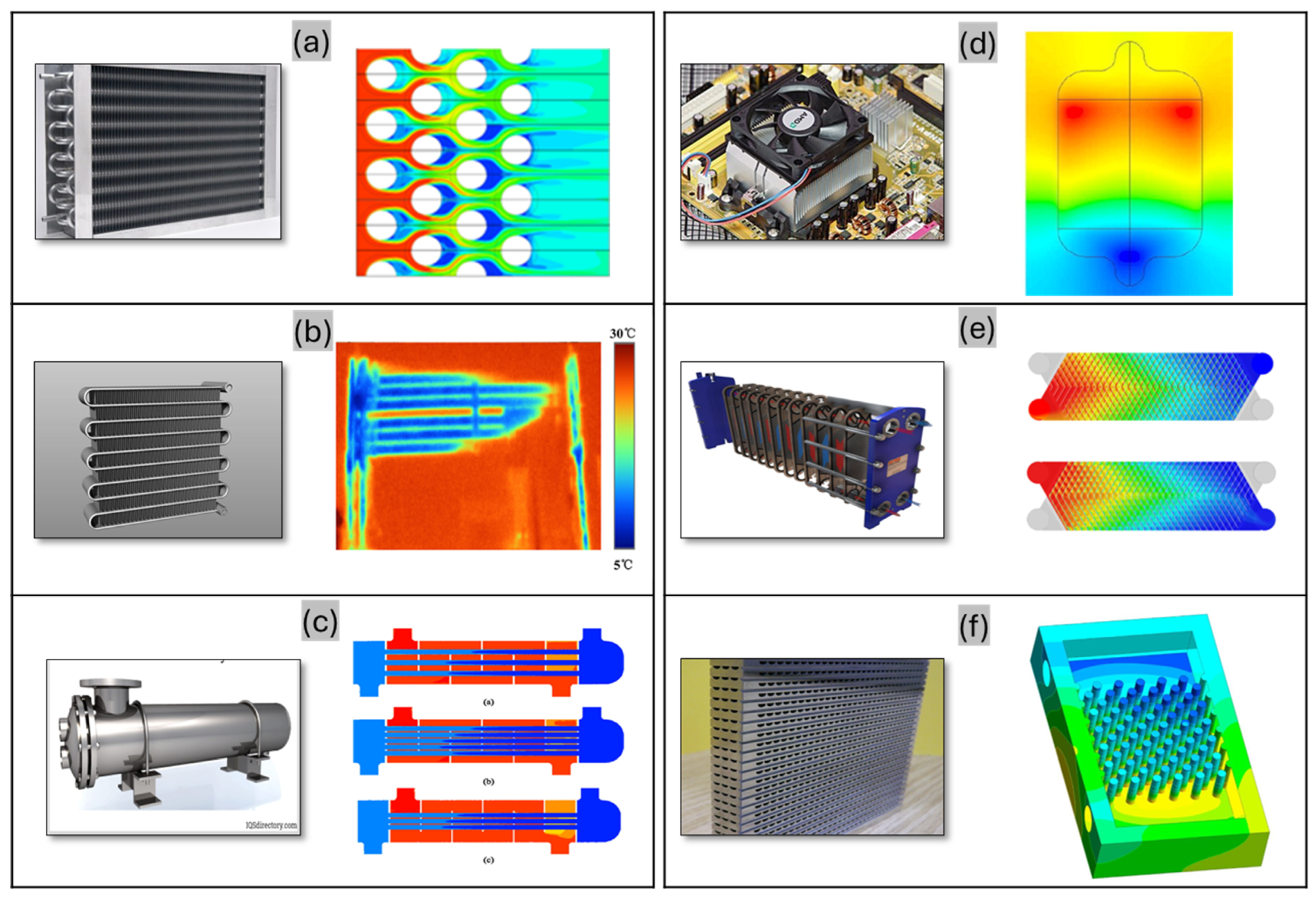
Figure 1. Contours of temperature non-uniformity in various HX types: (a) FTHX, (b) flat-tube HX, (c) shell-and-tube HX, (d) microchannel heat sink, (e) P-type HX, and (f) PCHX.
Energies 18 02751 g001
Figure 2. Contours of airflow non-uniformity in various HX types: (a,b) PHX, (c,d) FTHX, and (e) MCHXs.
Energies 18 02751 g002
Figure 3. Contours of airflow non-uniformity in PCHXs: (a) micro pin–fin heat sinks with square, circular, and triangular fin cross-sections; (b) hyperbolic inlet header in a straight-channel PCHX; (c) microchannel heat sink utilizing secondary flows in trapezoidal and parallel orientations; and (d) predicted flow maldistribution in a PCHX.
Energies 18 02751 g003
Figure 4. Refrigerant distribution in CHXs: (a) mass flow rate distribution on the refrigerant side of a multi-port mini-channel HX; (b) two-phase refrigerant distribution in a microchannel flat-tube HX; and (c) refrigerant distribution in an alternatively laminated microchannel tube (ALMT) HX with vertical headers.
Energies 18 02751 g004
Figure 5. Airflow non-uniformity in various HX configurations: (ad) Face velocity profiles in a FTHX. (e) Face velocity profiles for different rows of FTHX. (f) Velocity variation along the flow at the centerline in a microchannel HX.
Energies 18 02751 g005
Figure 6. Impact of non-uniformities on HX performance: (a) condenser capacity loss, (b) heat transfer reduction, (c) tube capacity variation under uniform vs. non-uniform airflow, and (d) capacity calculations using uniform vs. non-uniform airflow.
Energies 18 02751 g006
Table 1. Summary of numerical investigations.
AuthorsNature of DomainNumerical Details Modeling Approach
Wang et al. [23]Flow of gas–liquid refrigerant in a distributor• Three-dimensional
• Finite volume method
• 400,000 cells
• ANSYS Fluent
• Eulerian multiphase model
• Standard kε turbulence model
• Enhanced wall treatment
• Pressure-based solver with the SIMPLE algorithm
Zhang et al. [60]An air-cooled condenser in a steam-electric power plant• Three-dimensional
• Finite volume method
• 3,820,000 cells
• ANSYS Fluent
• Porous media model
• Fan modeled as a moving reference frame
• Standard kε turbulence model
Yashar et al. [124]A FTHX• Two-dimensional
Ranganayakulu et al. [88]A crossflow plate–fin compact HX• Finite element method• Mathematical model based on a Fourier series
Mishra et al. [102]Crossflow HX• Implicit finite difference method• Governing equations and boundary conditions solved using the Gauss–Seidel iterative technique
Srihari and Das [34]PHX• Finite difference method
• Comparison with analytical solution results
• Boundary conditions based on Danckwerts analysis [125]
Chin and Raghavan [108]Thermal performance of a FTHX• Two-dimensional
• 10 × 10 grid
• Continuous probability density functions
Datta et al. [119]A condenser in an automotive air conditioning system• CoilDesigner software• One-dimensional control volume energy balance for each port
Prabhakara Rao et al. [18]PHX• Control volume method
• Multipass configuration modeled as multiple exchangers
• Governing energy equations formulated
• Differential equations cast into a matrix form
Wasewar et al. [126]Flow distribution in the header of a PHX• Finite volume method
• No-slip boundary conditions
• 2,000,000 cells
• Single-phase model
• Standard kε turbulence model
• SIMPLE algorithm
• Solved using the tridiagonal matrix algorithm
Mao et al. [111]A multi-louvered FTHX• One-dimensional steady-state
• Finite volume method
• MATLAB-based custom code
• Refrigerant properties from REFPROP
Chung et al. [127]PCHXs• Conjugate heat transfer model• Modified porous media approach
Disclaimer/Publisher’s Note: The statements, opinions and data contained in all publications are solely those of the individual author(s) and contributor(s) and not of MDPI and/or the editor(s). MDPI and/or the editor(s) disclaim responsibility for any injury to people or property resulting from any ideas, methods, instructions or products referred to in the content.