Article

Multi-Objective Optimal Control of Variable Speed Alternating Current-Excited Pumped Storage Units Considering Electromechanical Coupling Under Grid Voltage Fault

1
Construction and Management Branch of China Southern Power Grid Energy Storage Co., Ltd., Guangzhou 510000, China
2
NR Electric Co., Ltd., Nanjing 210000, China
3
School of Electrical and Power Engineering, Hohai University, Nanjing 210000, China
*
Author to whom correspondence should be addressed.
Energies 2025, 18(11), 2750; https://doi.org/10.3390/en18112750
Submission received: 24 April 2025 / Revised: 19 May 2025 / Accepted: 19 May 2025 / Published: 26 May 2025

Abstract

:
Variable Speed AC-excited Pumped Storage Units (VSACPSUs) demonstrate advantages in flexibility, high efficiency, and fast response, and they play a crucial regulatory role in power systems with increasing renewable energy penetration. Typically connected to weak grids, conventional low-voltage ride-through (LVRT) control methods for these units suffer from single control objectives, poor adaptability, and neglect of electromechanical coupling characteristics. To address these limitations, this paper proposes a multi-objective optimization strategy considering electromechanical coupling under a grid voltage fault. Firstly, a positive/negative-sequence mathematical model of doubly-fed machines is established. Based on stator winding power expressions, the operational characteristics under a grid fault are analyzed, including stator current imbalance as well as oscillation mechanisms of active power, reactive power, and electromagnetic torque. Considering the differences in rotor current references under different control objectives, a unified rotor current reference expression is constructed by introducing a time-varying weighting factor according to expression characteristics and electromechanical coupling properties. The weighting factor can be dynamically adjusted based on operating conditions and grid requirements using turbine input power, grid current unbalance, and voltage dip depth as key indicators to achieve adaptive control optimization. Finally, a multi-objective optimization model incorporating coupling characteristics and operational requirements is developed. Compared with conventional methods, the proposed strategy demonstrates enhanced adaptability and significantly improved low-voltage ride-through performance. Simulation results verify its effectiveness.

1. Introduction

As a flexible, efficient, and clean regulating power source in modern power systems, pumped storage units (PSUs) play a vital role in ensuring the secure and stable operation of power grids [1,2]. The Medium- and Long-Term Development Plan for Pumped Storage [3] states, “By 2025, the total operational capacity of pumped storage shall exceed 62 GW, and by 2030, it shall reach approximately 120 GW”. Against this backdrop, pumped storage will undoubtedly serve as a foundational pillar in constructing new power systems with a high penetration of renewable energy [4].
Currently, most operational PSUs employ synchronous machines operating at fixed speeds, which suffer from low efficiency, intensified cavitation, and vibration when deviating from rated load or head conditions [5]. In contrast, Variable Speed Pumped Storage Units (VSPSUs) enable high-efficiency energy conversion across a wide speed range in both generating and pumping modes. Among these, Variable Speed AC-excited Pumped Storage Units (VSACPSUs) based on doubly-fed induction machines (DFIMs) have gained widespread adoption due to advantages such as reduced converter capacity [6].
Pumped storage units are often situated in mountainous areas with weak grid connections, imposing stringent requirements on voltage fault ride-through (FRT) capability. However, the DFIM’s stator is directly grid-connected, and its limited converter capacity renders it vulnerable to grid voltage disturbances, leading to overcurrent and constrained FRT performance. To enhance DFIMs’ FRT capability, extensive research has been conducted globally, primarily focusing on hardware protection and software optimization.
For hardware protection, reference [7] employed a DC chopper to mitigate DC-link voltage spikes during mild voltage faults, while severe faults trigger relay protection to disconnect the unit. Reference [8] deployed asymmetric damping resistors during asymmetrical faults, effectively suppressing rotor current and electromagnetic torque peaks, though the study was limited to typical generating conditions. Reference [9] derived the rotor current peak during three-phase short circuits by analyzing stator current expressions to determine crowbar resistance selection. Reference [10] further refined crowbar switching timing through a transient analysis of DFIMs. While these methods have improved low-voltage ride-through (LVRT) capability, fixed-parameter switching strategies struggle to adapt to complex operating conditions, and additional hardware compromises the cost advantage of DFIMs’ reduced converter capacity.
Given the limitations of hardware solutions, software optimization algorithms have been widely explored. Reference [11] introduced nonlinear feedforward signals into control loops to compensate for transient disturbances during severe faults, albeit at the cost of higher rotor-side converter (RSC) capacity. Reference [12] optimized current-loop damping characteristics via virtual resistance, addressing deficiencies in low-frequency damping. Reference [13] proposed a virtual inductance control method to enhance high-frequency damping. Reference [14] combined the merits of virtual resistance and inductance, proposing a virtual impedance control strategy to coordinately optimize damping across all frequency bands. While these methods have improved anti-disturbance capability during voltage faults, they neglect the unbalanced stator/rotor currents and double-frequency power/torque oscillations under asymmetrical faults, which threaten operational safety. To address this, reference [15] adopted a dual-dq control strategy to precisely regulate positive- and negative-sequence components, achieving objectives like stator power/current or rotor current fluctuation suppression. However, real-world operation demands simultaneous satisfaction of multiple objectives (e.g., power stabilization, torque oscillation attenuation), rendering single-objective control insufficient for complex requirements.
To bridge this gap, this paper proposes a multi-objective optimal control strategy for a grid voltage fault, incorporating electromechanical coupling effects. First, the operational characteristics of VSACPSUs under grid faults are analyzed based on the DFIM’s positive/negative-sequence mathematical model. Next, considering the divergence in rotor current references under different control objectives, a time-varying weight factor is introduced to construct a multi-objective optimization model that accounts for coupling dynamics and operational demands, thereby deriving optimal rotor current references. This approach adapts to diverse grid requirements and unit operating conditions, enabling multi-objective optimized control during voltage faults and significantly enhancing LVRT performance.
The main contributions of this paper are as follows:
(1)
A unified rotor current reference expression is developed by incorporating electromechanical coupling characteristics, which ensures consistent control across different fault scenarios and objectives;
(2)
A time-varying weighting factor mechanism is introduced to realize dynamic multi-objective optimization, enabling the control priorities to adaptively shift based on system operating conditions and fault severity;
(3)
A comprehensive LVRT control strategy is proposed for the VSACPSU under asymmetrical voltage faults, which simultaneously addresses active/reactive power oscillation suppression, torque fluctuation mitigation, and current unbalance reduction, leading to significantly improved grid fault adaptability and system stability.
The remainder of this paper is organized as follows: Section 2 presents the system configuration of the VSACPSU. Section 3 investigates its fault response characteristics. Section 4 introduces the proposed control strategy. Section 5 presents the simulation analysis. Section 6 concludes the paper and discusses future research directions.

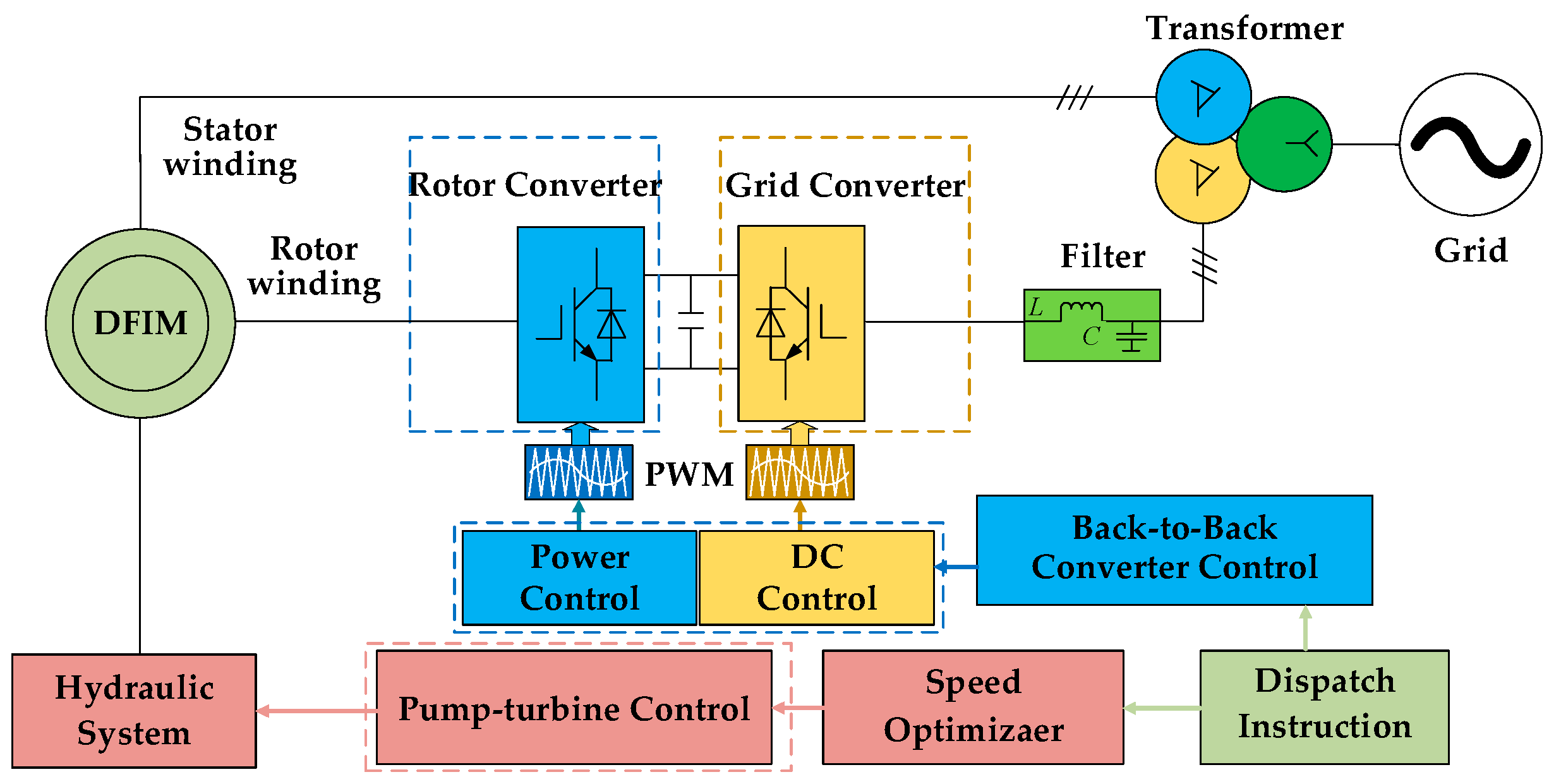
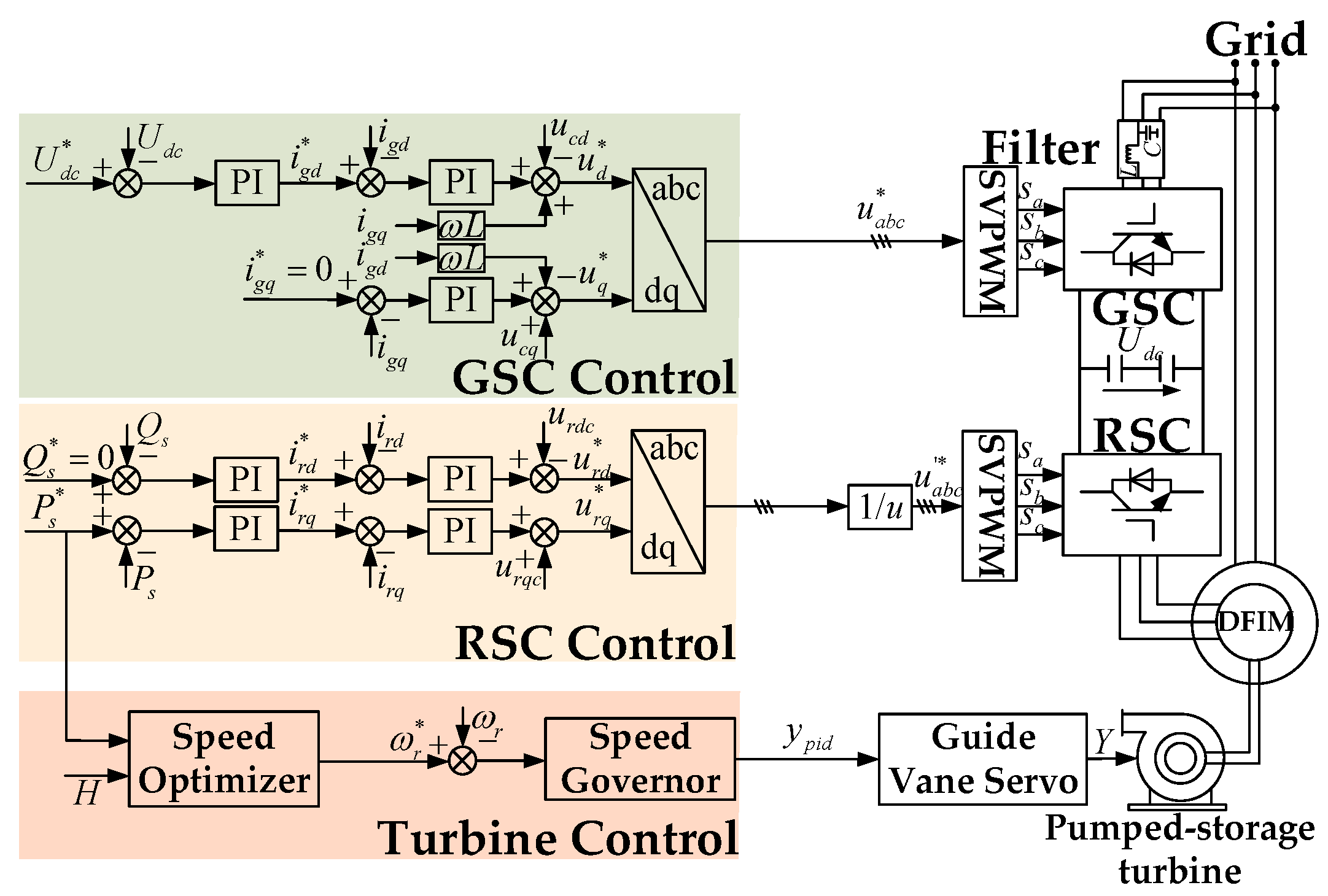
2. The System Configuration of Variable Speed AC-Excited Pumped Storage Units

Figure 1 shows the schematic diagram of a Variable Speed AC-excited Pumped Storage Unit, which consists of a pump turbine, a doubly-fed induction machine, a machine-side converter, a grid-side converter (GSC), and a grid interface. The stator of the DFIM is directly connected to the grid, while its rotor is connected to the grid through a back-to-back converter.
The pump-turbine converts hydraulic potential energy into mechanical energy, which is transmitted through the main shaft to the doubly-fed induction machine for electromechanical energy conversion. The back-to-back converter serves as the power transmission interface between the rotor and grid, ensuring bidirectional power flow.
The rotor-side converter employs a power–current dual-loop control scheme [16], enabling rapid and precise power regulation in response to grid demands. The grid-side converter utilizes a voltage–current dual-loop control strategy [17] to maintain constant DC-link voltage and facilitate efficient energy exchange between the generating unit and power grid [18].
A significant time scale disparity exists between electrical and mechanical systems, resulting in the substantially faster dynamic response of converter controls compared to the governor system. Consequently, the unit’s conventional control strategies are categorized as either power-priority control (Figure 2), typically adopted during the generation mode to ensure fast and stable tracking of power commands [19], or speed-priority control (Figure 3), generally implemented in pumping operation to achieve rapid and robust response to speed references [20].
Under grid voltage fault conditions, negative-sequence components appear in the system. The voltage and flux linkage equations of the doubly-fed induction machine in the positive- and negative-sequence reference frames are expressed separately as follows:
Positive-sequence reference frame:
v s 1 = R s i s 1 + d ψ s 1 d t + j ω s ψ s 1 v r 1 = R r i r 1 + d ψ r 1 d t + j s ω s ψ r 1
ψ s 1 = L s i s 1 + L m i r 1 ψ r 1 = L m i s 1 + L r i r 1
Negative-sequence reference frame:
v s 2 = R s i s 2 + d ψ s 2 d t j ω s ψ s 2 v r 2 = R r i r 2 + d ψ r 2 d t j ( 2 s ) ω s ψ r 2
ψ s 2 = L s i s 2 + L m i r 2 ψ r 2 = L m i s 2 + L r i r 2
To facilitate readers’ understanding of the mathematical models and expressions used in this paper, a symbol definition table has been added in Appendix A. This table provides detailed descriptions of the variables and parameters appearing in the key equations throughout the text. For more information, please refer to Appendix A.

3. Operating Characteristics of Variable Speed AC-Excited Pumped Storage Units Under Grid Voltage Faults

This section analyzes the operating characteristics of Variable Speed AC-excited Pumped Storage Units under grid voltage faults, including both symmetrical voltage fault conditions and asymmetrical fault conditions. The aim is to reveal the electromechanical response and key challenges faced by the system during different types of grid disturbances, providing the foundation for subsequent control strategy design.

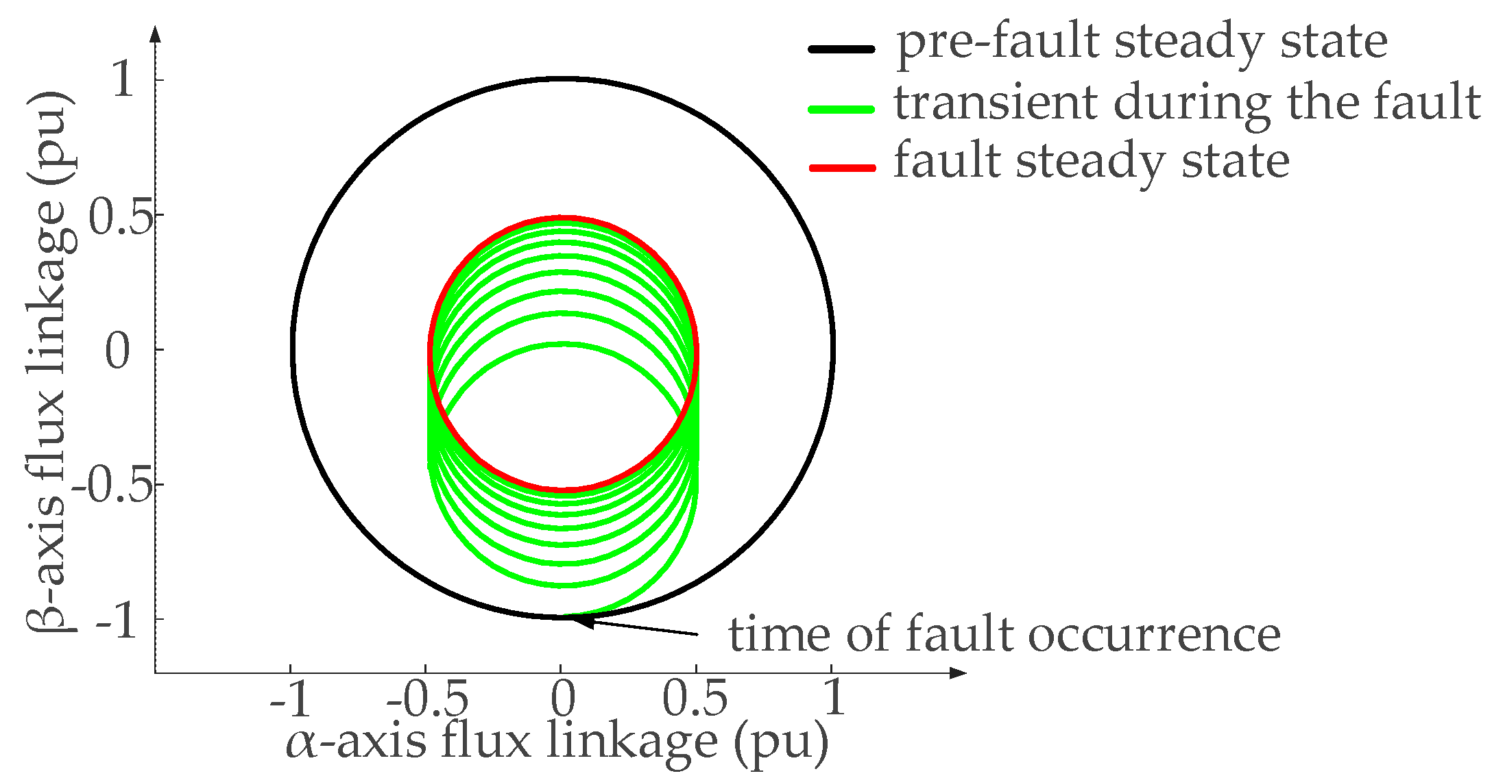
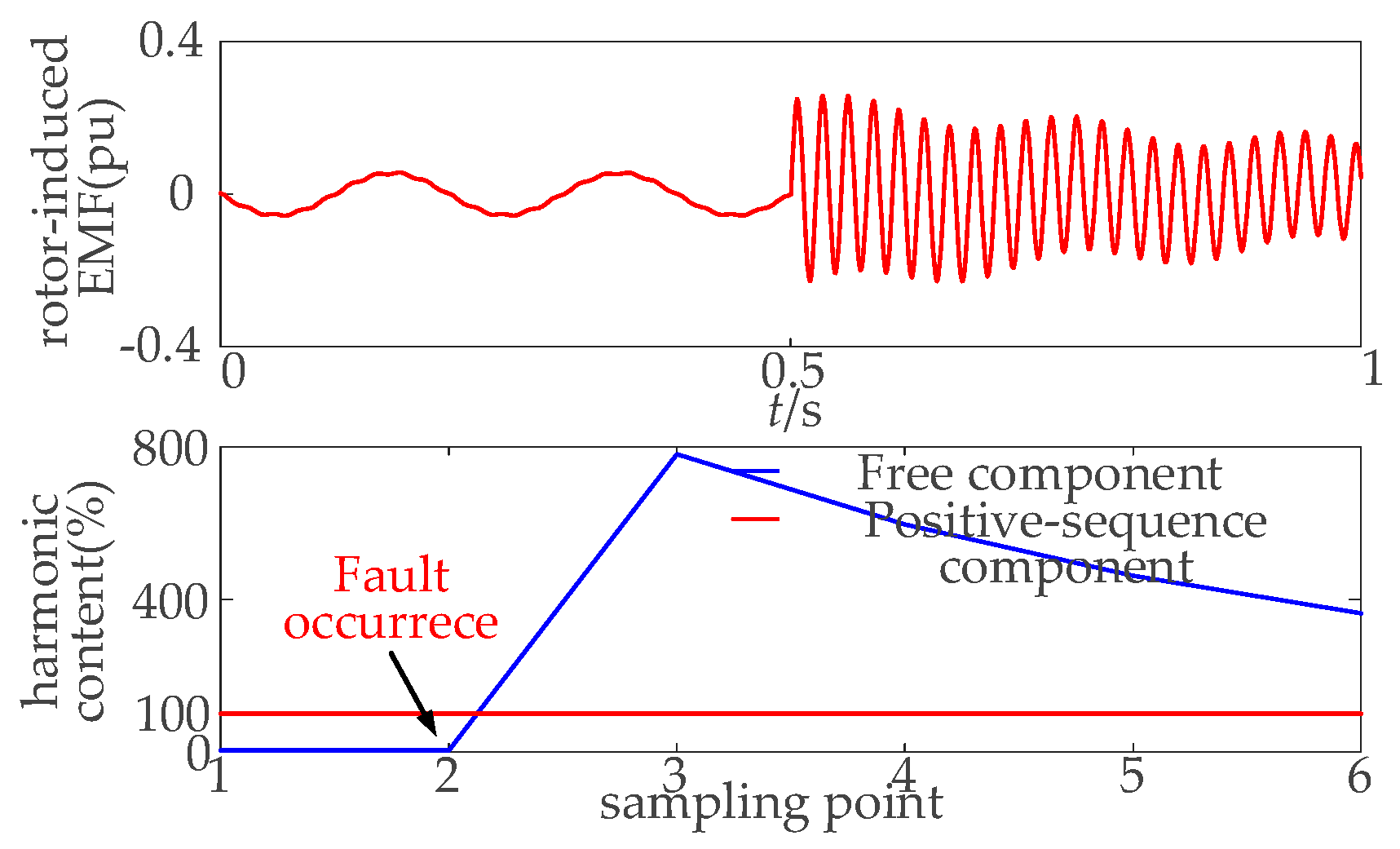
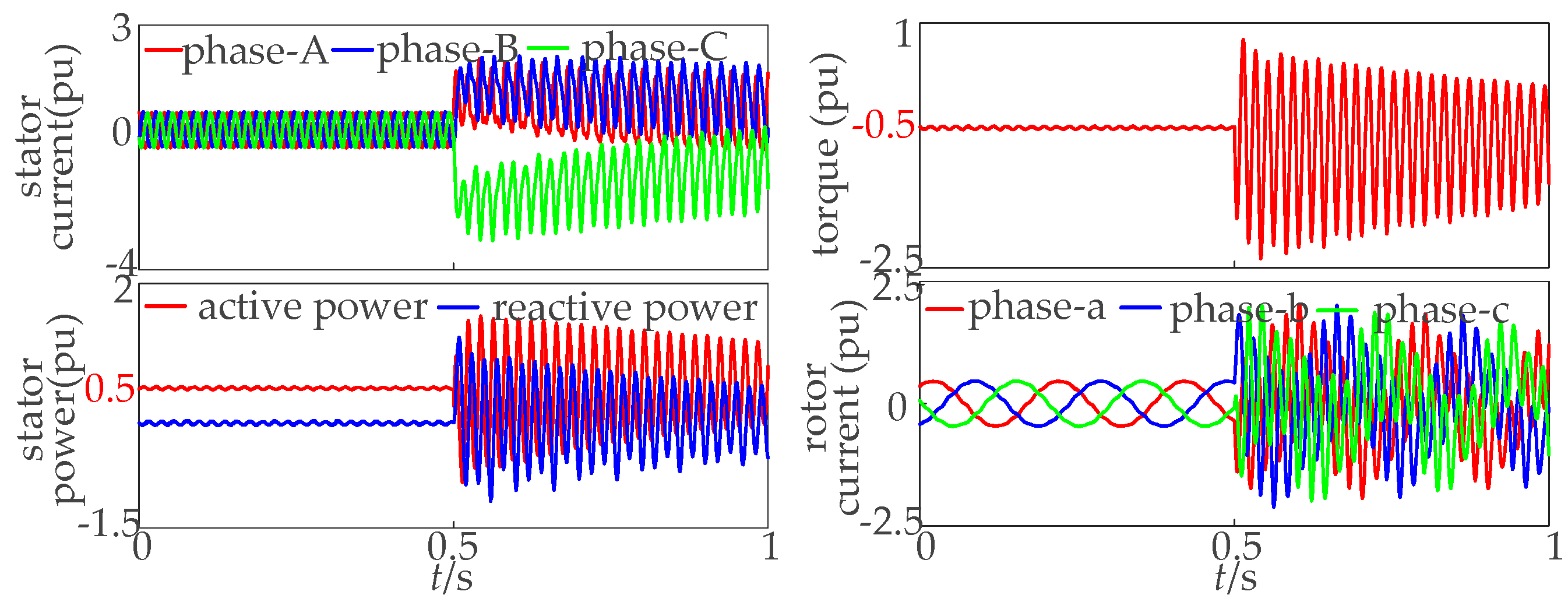
3.1. Operating Characteristics of DFIM Under a Symmetrical Grid Voltage Fault

Under symmetrical grid fault conditions, the operating characteristics of VSACPSUs are primarily reflected in the symmetrical drop of stator voltage and the resulting electromagnetic transients. Symmetrical faults are typically caused by three-phase short circuits, which significantly reduce the grid voltage magnitude while maintaining balanced three-phase voltages.
When a voltage fault occurs in the power grid, the magnetic flux linkage cannot change instantaneously and must remain continuous at the fault inception, as expressed in the following equation.
ψ s ( t < 0 ) = V s j ω s e j ω s t ψ s ( t 0 ) = ( 1 p ) V s j ω s e j ω s t + p V s j ω s e t / τ s
Before the voltage fault occurs, the stator flux linkage rotates at the grid synchronous speed. During the fault, the flux linkage can be decomposed into two components.
The forced component continues to rotate at the grid frequency with a constant magnitude. The free component remains stationary relative to the stator and decays exponentially according to the stator time constant.
This behavior reflects a dynamic transition from one steady state to another. The evolution of the stator flux linkage under voltage fault conditions is illustrated in Figure 4, which provides an intuitive representation of the electromagnetic transient process during the voltage fault.
Both components of the stator flux linkage induce electromotive forces (EMFs) in the rotor. Among them, the free component gives rise to high-frequency EMFs on the rotor side, which in turn lead to rotor overcurrent. This overcurrent not only imposes stress on the rotor-side converter but may also damage power electronic devices. Moreover, significant oscillations in the electromagnetic torque are observed during the fault period, which result from the interaction between the free component of the stator flux linkage and the rotor current. These torque oscillations are further transmitted to the mechanical side, potentially affecting the mechanical stability of the unit.
As shown in Figure 5 and Figure 6, during the voltage fault, a higher voltage is induced in the rotor due to the free component of the stator flux linkage, with the maximum value occurring at the moment of the fault. Before the fault, the rotor-induced electromotive force follows a sinusoidal variation with a frequency of 5 Hz, corresponding to the machine’s slip frequency. During the fault, a 45 Hz sinusoidal wave, induced by the free component, is superimposed on the rotor EMF. The introduction of this high-frequency harmonic component not only exacerbates the fluctuations in the rotor current but also leads to pulsations in the electromagnetic torque. This, in turn, subjects the shaft system to periodic torque shocks, affecting the safe and stable operation of the unit.

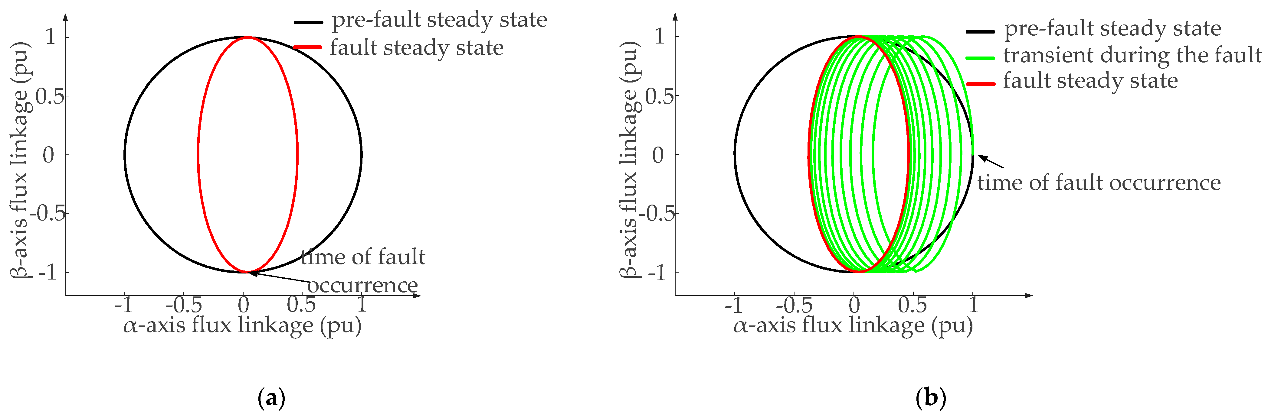
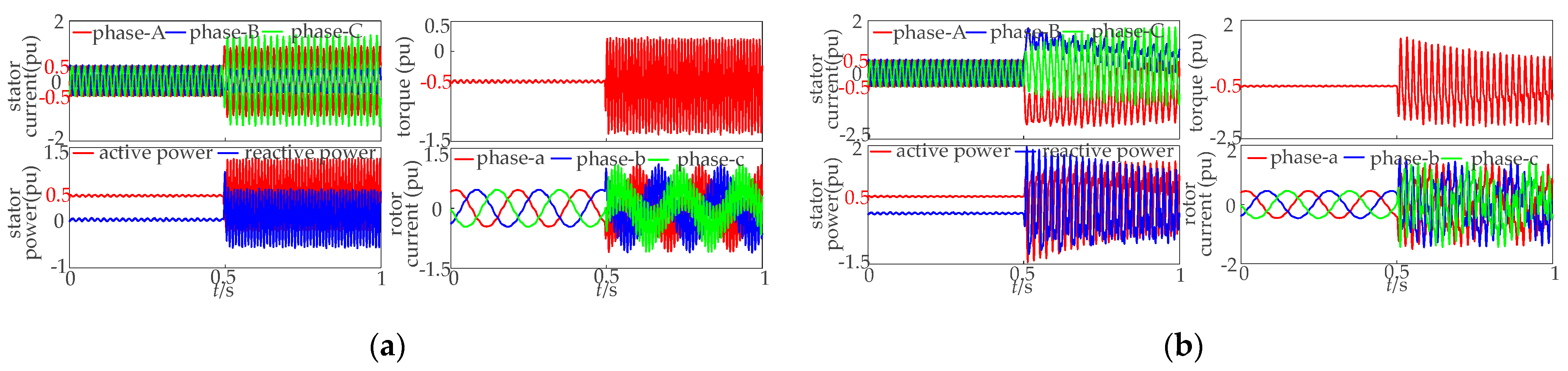
3.2. Operating Characteristics of DFIM Under a Symmetrical Grid Voltage Unbalanced Fault

When a grid voltage unbalanced fault occurs, the resulting unbalanced stator and rotor current in the doubly-fed induction machine leads to double-frequency oscillations in both reactive and active power, which negatively impact the stable operation of the system. The most common fault in the grid is a single-phase-to-ground short circuit. Therefore, this paper focuses on analyzing the machine’s operating characteristics under a single-phase-to-ground fault.
Unlike symmetrical faults, during an unbalanced fault, the magnitude and phase of the stator flux linkage components are time-varying due to the opposite rotation directions of the positive- and negative-sequence components. This results in an elliptical trajectory of the stator flux linkage, a typical indicator of unbalanced voltage conditions.
As shown in Figure 7 and Figure 8, the severity of the flux linkage disturbance depends on the fault inception time. When the fault occurs at t = 0, the positive- and negative-sequence components are aligned, and the free flux linkage component is minimized, resulting in minor transient effects. In contrast, when the fault occurs at t = T/4 (where T is the grid period), the two components are in opposition, and the free flux linkage reaches its maximum, producing the most severe transient behavior.
The interaction between these time-varying flux components gives rise to multi-frequency coupling, which exacerbates rotor current fluctuations and leads to secondary harmonic oscillations in electromagnetic torque. This not only reduces mechanical stability but may also excite resonances, posing a risk to safe operation.
Additionally, as illustrated in Figure 9, unbalanced faults cause significant imbalances in the stator current and power output, which can accelerate insulation aging due to localized heating and degrade the overall energy conversion efficiency. Therefore, a detailed understanding of the machine’s dynamic behavior under unbalanced fault conditions is crucial for improving its fault ride-through capability.

4. Multi-Objective Optimal Control of Variable Speed AC-Excited Pumped Storage Units Under a Grid Voltage Fault

This section proposes a multi-objective optimal control strategy for a VSACPSU under grid voltage fault conditions based on time-varying weighting factors. By introducing a time-varying weighting mechanism, a multi-objective optimization model is constructed that accounts for electromechanical coupling characteristics and complex operational requirements. The proposed strategy not only ensures fault ride-through capability but also effectively mitigates power and torque oscillations as well as stator current imbalances.

4.1. Calculation of the Unified Rotor Reference Current

Assuming that a single-phase-to-ground fault occurs in phase A of the power grid, with a voltage fault depth of p, the following expression can be obtained:
v s 1 = ( 1 p / 3 ) v s v s 2 = ( p / 3 ) v s v s 0 = ( p / 3 ) v s
Since the motor neutral point is ungrounded, the zero-sequence component of the voltage does not affect the machine’s behavior.
According to the instantaneous power theory, the expression for the instantaneous power of the stator winding is given by:
P s = Re v s i s * Q s = Im v s i s *
In Equation (7), the symbol “*” denotes the complex conjugate of the corresponding vector.
Expanding Equation (7) yields:
P s 0 Q s 0 P s cos Q s cos P s sin Q s sin = v s d 1 v s q 1 v s d 2 v s q 2 v s q 1 v s d 1 v s q 2 v s d 2 v s d 2 v s q 2 v s d 1 v s q 1 v s q 2 v s d 2 v s q 1 v s d 1 v s q 2 v s d 2 v s q 1 v s d 1 v s d 2 v s q 2 v s d 1 v s q 1 i s d 1 i s q 1 i s d 2 i s q 2
As indicated by Equation (8), the presence of negative-sequence voltage and current components results in double-frequency oscillations in the instantaneous stator power, including active power components Ps sin and Ps cos, and reactive power components Qs sin and Qs cos. The more severe the voltage imbalance in the grid, the higher the proportion of negative-sequence components, which intensifies the oscillatory behavior of the system and adversely affects the safe and stable operation of the unit.
According to the flux linkage equations of the DFIM and Equation (8), four rotor current components—ird1, irq1, ird2, and irq2—can be used as control variables under asymmetrical voltage fault conditions. Therefore, in addition to independently decoupled control of the average active and reactive stator power outputs Ps0 and Qs0, the following control objectives can be defined based on actual system requirements:
Objective I: To maintain grid frequency stability, mitigate frequency fluctuations, improve grid reliability, and suppress power fluctuations caused by renewable energy sources, the stator active power is regulated to be constant, i.e., eliminating the double-frequency oscillatory components in the stator active power.
Objective II: To ensure thermal balance among the three-phase stator windings and meet the grid’s current unbalance tolerance, the stator current is regulated to maintain phase balance.
Objective III: To maintain voltage stability, reduce voltage fluctuations, and enhance grid reliability, the stator reactive power is regulated to be constant, i.e., eliminating the double-frequency oscillatory components in the stator reactive power.
Under grid voltage fault conditions, Objectives I–III are selected as the primary goals for multi-objective optimization control based on considerations of grid stability and power quality. However, these objectives are inherently coupled. For instance, both Objectives I and III involve suppression of double-frequency power oscillations, while Objective II (current balancing) interacts with the power control objectives, making it difficult to achieve all targets simultaneously.
To address this issue, a weighting factor K is introduced to construct a unified expression for the rotor reference current, enabling coordinated multi-objective optimization control. Based on the aforementioned theoretical analysis, the selection of control objectives determines the computation of the rotor current reference. To simplify the calculation, the stator voltage is oriented along the q-axis.
By incorporating the weighting factor K, the unified expression of the rotor reference current is formulated as:
i r d 1 = 2 3 L s L m Q s 0 v s q 1 R 1 K v s q 2 2 + v s q 1 ω s L m i r q 1 = 2 3 L s L m P s 0 v s q 1 D K 1 v s q 2 2 i r d 2 = 2 3 L s L m 2 K Q s 0 v s q 2 K + 1 R K 1 D v s q 2 ω s L m i r q 2 = 2 3 L s L m 2 K P s 0 v s q 2 K 1 R K + 1 D
The range of weighting factor K is [−1, 1]. When K = 1, the objective is to minimize the fluctuation of the stator active power, representing a single-target control. When K = 0, the objective is to minimize the imbalance of the stator grid current, representing another single-target control. When K = −1, the objective is to minimize the fluctuation of the stator reactive power, corresponding to a third single-target control.

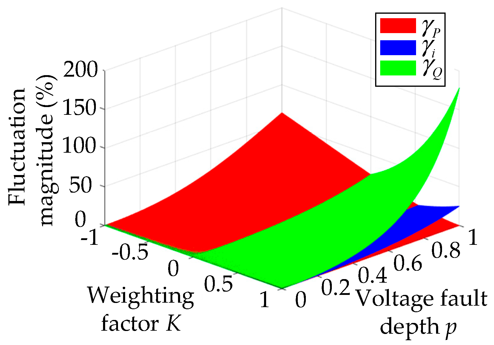
4.2. Construction of the Multi-Objective Optimization Model

As can be seen from Equation (8), when the negative-sequence current is controlled to be zero, three-phase balance of the stator current is achieved. However, the effect of the stator negative-sequence voltage still causes the stator active and reactive power to exhibit double-frequency oscillations. If the oscillations in stator active or reactive power are suppressed, the stator negative-sequence current will not be zero. In other words, it is not possible to simultaneously suppress the negative-sequence current and eliminate the oscillations in both active and reactive power. Improving one control objective may lead to a deterioration in the performance of another.
Therefore, it is necessary to construct a multi-objective optimization model that can adjust the weighting factor K according to the actual conditions, thereby coordinating the multiple control objectives and enhancing the overall system control performance.
To provide a more intuitive display of the control performance, evaluation indices for stator power fluctuation and stator grid current imbalance are introduced. The relationship between these evaluation indices and the variations in K and p is shown in Figure 10.
γ P = P s cos 2 + P s sin 2 P s 0 2 + Q s 0 2 = 1 K 2 λ P s 0 1 K λ 2 2 + λ Q s 0 1 + K λ 2 2 P s 0 2 + Q s 0 2 γ i = i s d 2 2 + i s q 2 2 i s d 1 2 + i s q 1 ` 2 = K λ 2 γ Q = Q s cos 2 + Q s sin 2 P s 0 2 + Q s 0 2 = 1 + K 2 λ P s 0 1 K λ 2 2 + λ Q s 0 1 + K λ 2 2 P s 0 2 + Q s 0 2
It is worth noting that γP, γi, and γQ are scalar indicators used to quantify control performance. γP is defined as the square of the ratio between the active power double-frequency fluctuation and the power reference. γQ is similarly defined for reactive power. γi is the ratio of the negative-sequence to the positive-sequence component of the stator current. All indicators are expressed as percentages.
In addition, to ensure the safe and stable operation of the VSACPSU during the grid voltage fault, and in compliance with grid operating regulations and the requirements for torque ripple suppression, the following constraints are set in this study: the double-frequency fluctuations of the stator active and reactive power must be within 5%, and the stator current imbalance must not exceed 1%.
The coordination between reducing the stator active and reactive power fluctuations and minimizing the current imbalance constitutes a multi-objective optimization problem. The weighted method offers high flexibility, making it suitable for different application scenarios and simplifying the calculation and analysis process. Therefore, the multi-objective function is converted into a single-objective function for optimization and solving using the weighted method. The objective function is constructed as shown in Equation (11):
min F K = α 1 γ P + α 2 γ i + α 3 γ Q
The coefficient α1 is positively correlated with the input power of the water turbine. When the water turbine input power is high, priority is given to reducing stator active power fluctuations. The range of α1 is [0, 1]. The coefficient α2 is positively correlated with the stator grid current imbalance. When the grid has higher requirements for stator grid current imbalance, priority is given to reducing stator grid current imbalance. The range of α2 is [0, 1]. The coefficient α3 is positively correlated with the depth of the voltage dip. When the voltage dip is deeper, priority is given to reducing stator reactive power fluctuations. The range of α3 is [0, 1]. Additionally, α1 +α2 +α3 = 1.
Through the optimal solution algorithm, the variation trend of the K value with respect to the coefficients α1, α2, and α3 can be obtained as shown in Figure 11.

4.3. Multi-Objective Coordinated Control Strategy Under Grid Voltage Faults

The control system structure of the machine-side converter under grid voltage faults is shown in Figure 12. The instantaneous symmetrical component method is used to extract the positive and negative sequence components of the stator voltage, and phase-locking is performed on both the positive and negative sequence components to obtain synchronization signals. This approach aims to effectively control the positive and negative sequence components, improve system performance, and reduce torque and power fluctuations. The negative sequence component of the rotor current is obtained using a filter. The control system adopts a master–slave control structure for the positive and negative sequence current loops. This method enhances the stability and fault response capability of the system under asymmetric faults by decoupling the control of the positive and negative sequence currents.
When a voltage fault is detected at the grid connection point, the instantaneous symmetrical component method is first applied to decompose the grid voltage into positive and negative sequence components and to extract their corresponding phase angles. Then, based on the operating conditions of the unit and the requirements of the power grid, the coefficients α1, α2, and α3 are determined. By solving the objective function, the reference rotor current command is obtained, thereby realizing multi-objective coordinated control of the VSACPSU.

5. Simulation Analysis

A simulation model of the VSACPSU was built in MATLAB/Simulink, with the main parameters listed in Table 1. Under unbalanced fault conditions, the performance of the conventional single-objective control strategy is compared with that of the proposed coordinated multi-objective control strategy, highlighting their respective advantages and disadvantages.

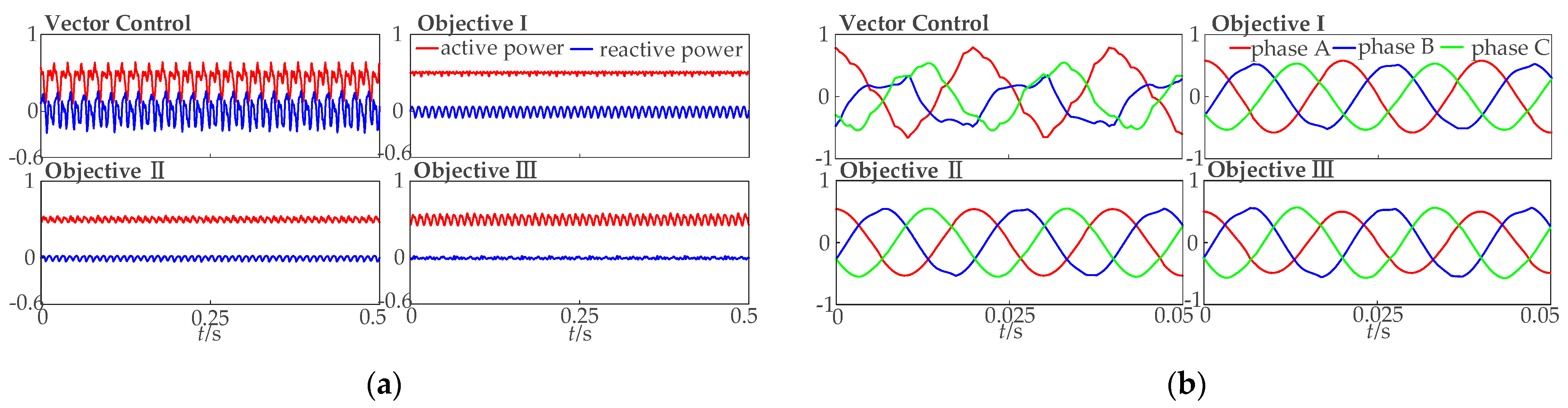
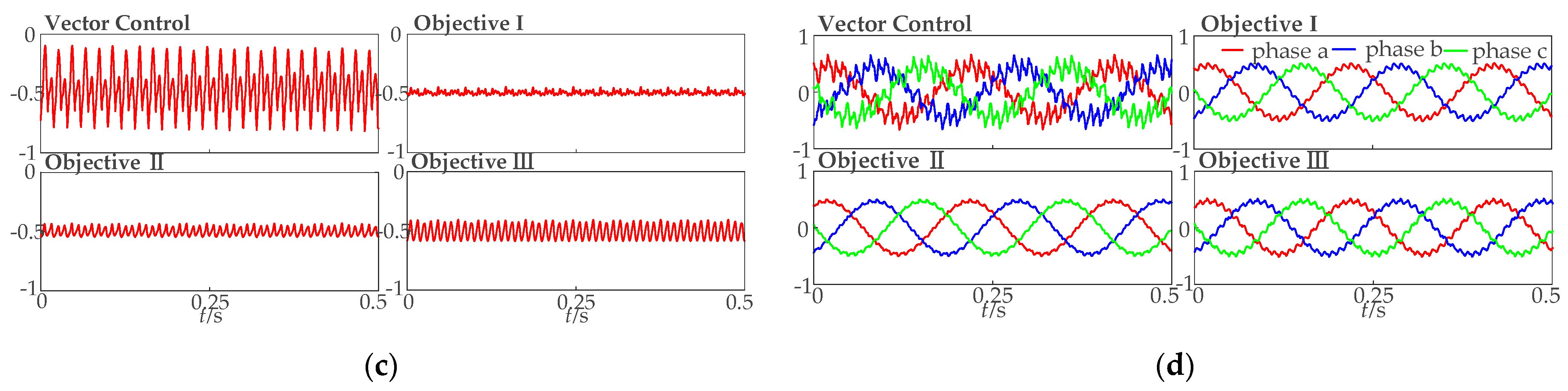
5.1. Simulation of the Conventional Control Strategy

Based on the theoretical analysis presented earlier, simulation analyses of the conventional vector control strategy and the dual-dq control strategy are carried out in Simulink. The simulation scenario considers an unbalanced fault occurring in the power grid, in which the amplitude of phase A voltage drops by 20%, resulting in a voltage unbalance factor of 7%. Under this condition, the slip is set to s = 0.1, with the stator active and reactive power set to Ps0 = 0.5 pu and Qs0 = 0 pu, respectively.
Figure 13 presents the control performance of traditional vector control and dual-dq control under three individual objectives, serving as a reference for comparison with the proposed multi-objective optimization strategy discussed later. Specifically, Objective I eliminate the oscillation of stator active power and reduces torque pulsations but fails to address current imbalance and reactive power oscillation. Objective II successfully reduces the stator current imbalance to nearly zero and suppresses rotor current fluctuations to a certain extent; however, it shows limited effectiveness in controlling active and reactive power oscillations. Objective III focuses on eliminating stator reactive power oscillations yet provides only marginal improvement in active power and rotor current stability. The evaluation metrics derived from the simulation results indicate that each single-objective control strategy enhances one specific performance indicator while compromising others. These findings highlight the need for a coordinated multi-objective control approach, as proposed in this paper, to achieve balanced and comprehensive system performance within defined constraints.

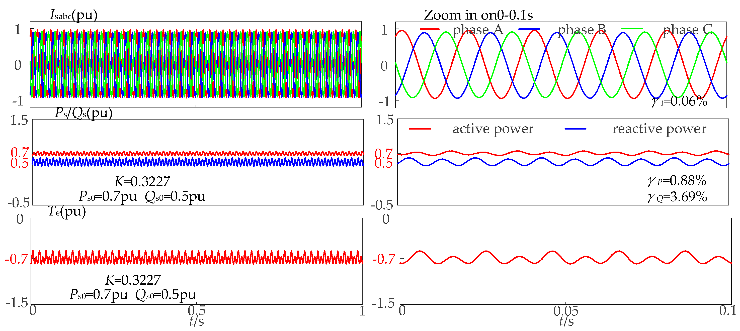
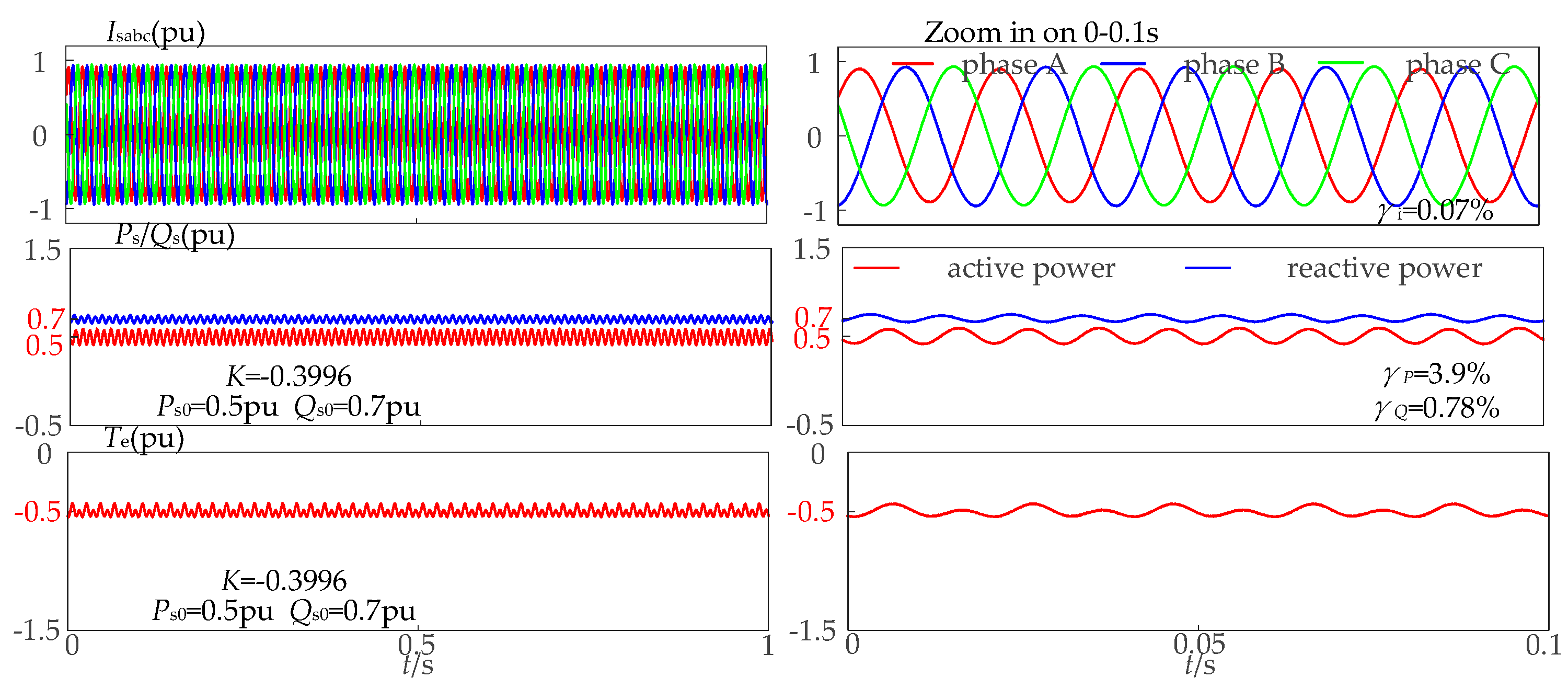
5.2. Simulation of the Proposed Multi-Objective Control Strategy

The proposed multi-objective optimization control strategy is simulated in Simulink under asymmetric fault conditions. In Simulation Case 1, the grid experiences an unbalanced fault where the A phase voltage drops by 20%, resulting in a voltage unbalance factor of 7%. The steady-state output powers are set to Ps0 = 0.7 pu and Qs0 = 0.5 pu. The control objective is to satisfy the reactive power fluctuation constraint (i.e., γQ < 5%) while minimizing active power oscillation and stator current imbalance.
Simulation results show that by adjusting the weighting factor K according to system conditions, the proposed control strategy effectively coordinates multiple objectives. It ensures compliance with reactive power fluctuation limits and simultaneously reduces active power ripple and current unbalance, thereby improving system performance under asymmetric voltage faults.
From Figure 14, it can be observed that while meeting the predefined constraint for reactive power fluctuation (γQ < 5%), the proposed multi-objective control strategy also achieves a minimal active power fluctuation and stator current imbalance. Compared with the single-objective strategies shown in Figure 13, this result confirms that the proposed approach can effectively coordinate multiple control objectives.
Simulation Case 2 Settings: Ps0 = 0.5 pu and Qs0 = 0.7 pu. The control objective is to satisfy the active power fluctuation requirement (γP < 5%) while simultaneously reducing reactive power fluctuations and stator current imbalance.
Figure 15 illustrates the system performance under the constraint of active power fluctuation. Specifically, while ensuring that the active power fluctuation remains within the predefined limits, the proposed strategy effectively minimizes the reactive power fluctuation and the stator current imbalance.
Figure 16 presents a comparison of key evaluation metrics under asymmetric voltage fault conditions. The figure illustrates that under the conventional vector control strategy, power fluctuations reach up to 160%, posing a significant threat to the safe operation of the unit. While the single-objective control method successfully achieves its respective target, it lacks the ability to coordinate multiple objectives, thereby limiting the exploitation of the full LVRT potential of the unit. In contrast, the proposed strategy effectively balances multiple control objectives within the predefined constraints, significantly enhancing the LVRT capability.
To verify the effectiveness of the proposed strategy under complex operating condition variations, Simulation Case 3 is configured as follows: The grid experiences an asymmetric fault, with a 20% voltage fault in Phase A and 7% grid unbalance. The initial operating point is set to Ps0 = 0.5 pu and Qs0 = 0 pu, with the control objective of satisfying reactive power fluctuation requirements (γQ < 5%) while reducing active power fluctuations and stator current imbalance. At t = 0.5 s, the operating point changes to Ps0 = 0.76 pu and Qs0 = 0.4 pu, with the control objective shifting to meeting active power fluctuation requirements (γP < 5%) while minimizing reactive power fluctuations and stator current imbalance.
The multi-objective cooperative control simulation results are shown in Figure 17. During the 0–0.5 s period, the reactive power fluctuation was maintained at 5%, satisfying the predefined safety threshold. Under this condition, the active power fluctuation was reduced to 0.37% with a stator current imbalance of only 0.17%. In the subsequent 0.5–1 s interval, the active power fluctuation was controlled within 4.1% (meeting the safety requirement), while achieving complete elimination of stator current imbalance (0%) and maintaining reactive power fluctuation at a minimal 0.68%.
These simulation results demonstrate that the proposed multi-objective optimization strategy significantly enhances the generator set’s low-voltage ride-through capability and improves its operational adaptability under complex grid conditions.

6. Conclusions

To address the limitations of a single objective and low adaptability in traditional LVRT strategies for VSACPSUs, this paper analyzes the electromechanical coupling characteristics of the system under both symmetrical and asymmetrical grid voltage faults. A multi-objective optimization control strategy incorporating time-varying weighting factors is proposed to coordinate active power support, torque ripple suppression, and current balance according to dynamic operating conditions.
Simulation results under various grid fault scenarios demonstrate that the proposed method effectively improves LVRT capability, reduces rotor torque fluctuations, and minimizes negative-sequence currents. Compared with conventional control strategies, the proposed method exhibits superior adaptability and robustness.
While the proposed control strategy demonstrates promising performance in simulation under grid fault conditions, it is currently limited to a single-unit system. In practical applications, multiple pumped storage units are often operated in coordination, which introduces challenges related to inter-unit communication, synchronization, and dynamic response discrepancies. Moreover, the integration of pumped storage with other renewables such as wind or solar adds further complexity. Future work will explore extending the proposed approach to multi-unit scenarios and embedding the control into grid-level simulations.

Author Contributions

Conceptualization, T.L. (Tao Liu) and T.F.; Methodology, X.Y.; Software, Y.L., X.Y., and C.Z.; Validation, Z.M.; Formal analysis, Y.L. and W.Y.; Investigation, T.L. (Teng Liu); Resources, T.L. (Tao Liu) and C.Z.; Data curation, T.L. (Tao Liu); Writing—original draft preparation, X.Z. and T.F.; Writing—review and editing, X.Z.; Visualization, Y.L. and X.Y.; Supervision, W.Y. and C.Z.; Project administration, W.Y. and T.L. (Teng Liu) All authors have read and agreed to the published version of the manuscript.

Funding

This research received no external funding.

Data Availability Statement

The original contributions presented in this study are included in the article. Further inquiries can be directed to the corresponding author.

Conflicts of Interest

Tao Liu and Xiaolong Yang were employed by the Construction and Management Branch of China Southern Power Grid Energy Storage Co., Ltd. Yu Lu, Ziqiang Man, Wei Yan, Teng Liu and Changjiang Zhan were employed by the NR Electric Co., Ltd. The remaining authors declare that the research was conducted in the absence of any commercial or financial relationships that could be construed as a potential conflict of interest.

Abbreviations

The following abbreviations are used in this manuscript:
PSUPumped Storage Unit
VSPSUVariable Speed Pumped Storage Unit
VSACPSUVariable Speed AC-excited Pumped Storage Unit
DFIMDoubly-fed induction machine
FRTFault ride-through
LVRTLow-voltage ride-through
RSCRotor-side converter
GSCGrid-side converter
EMFElectromotive force

Appendix A

The table below provides descriptions of the variables and parameters used in the main equations throughout the paper.
Table A1. Variable definition table.
VariablePhysical Meaning
vs1Positive-sequence component of stator three-phase voltage
vs2Negative-sequence component of stator three-phase voltage
vs0Zero-sequence component of stator three-phase voltage
is1Positive-sequence component of stator three-phase current
is2Negative-sequence component of stator three-phase current
ψs1Positive-sequence component of stator flux linkage
ψs2Negative-sequence component of stator flux linkage
ωsGrid angular velocity
sSlip ratio
Ps0Average value of stator active power
Ps cosDouble-frequency cosine component of stator active power
Ps sinDouble-frequency sine component of stator active power
Qs0Average value of stator reactive power
Qs cosDouble-frequency cosine component of stator reactive power
Qs sinDouble-frequency sine component of stator reactive power
λλ = vs2/vs1
R R = ( v s d 1 2 + v s q 1 2 ) + ( v s d 2 2 + v s q 2 2 )
D D = ( v s d 1 2 + v s q 1 2 ) ( v s d 2 2 + v s q 2 2 )

References

  1. Zhu, Z.; Tan, X.; Lu, X.; Liu, D.; Li, C. Hopf Bifurcation and Parameter Sensitivity Analysis of a Doubly-Fed Variable-Speed Pumped Storage Unit. Energies 2022, 15, 204. [Google Scholar] [CrossRef]
  2. Grigorescu, A.; Ion, A.-E.; Lincaru, C.; Pirciog, S. Synergy Analysis of Knowledge Transfer for the Energy Sector within the Framework of Sustainable Development of the European Countries. Energies 2022, 15, 276. [Google Scholar] [CrossRef]
  3. Wenke, H. China’s Energy Transition: Progress and Outlook from the “14th Five-Year Plan” to the “15th Five-Year Plan”. China Oil Gas 2025, 32, 1–10. [Google Scholar]
  4. Esmaeilian, H.-R.; Fadaeinedjad, R.; Bakhshai, A. Performance Evaluation and MPPT Control of a Variable-Speed Pump-as-Turbine System. IEEE Syst. J. 2023, 17, 3117–3126. [Google Scholar] [CrossRef]
  5. Chen, Y.; Xu, W.; Liu, Y.; Mao, Z. Dynamical Response Comparison Between Variable Speed and Synchronous Speed Pumped-Storage Units in Turbine Mode. IEEE Trans. Energy Convers. 2024, 39, 2490–2503. [Google Scholar] [CrossRef]
  6. Iliev, I.; Vedi, C.; Hlhaug, O.-G. Variable-speed operation of Francis turbines: A review of the perspectives and challenges. Renew. Sustain. Energy Rev. 2019, 103, 109–121. [Google Scholar] [CrossRef]
  7. Semwal, R.-R.; Joseph, A.; Chelliah, T.-R. Two-Stage Protection Circuit for a Multi-channeled Power Electronic Converter Fed Large Asynchronous Hydro generating Unit. IEEE Trans. Ind. Appl. 2019, 55, 5947–5959. [Google Scholar] [CrossRef]
  8. Damdoum, A.; Slama-Belkhodja, I.; Pietrzak-David, M.; Debbou, M. Low Voltage Ride-Through Strategies for Doubly Fed Induction Machine Pumped Storage System under Grid Faults. Renew. Energy 2016, 95, 248–262. [Google Scholar] [CrossRef]
  9. Morren, J.; de Haan, S.W.H. Short-circuit current of wind turbines with doubly fed induction generator. IEEE Trans. Energy Convers. 2007, 22, 174–180. [Google Scholar] [CrossRef]
  10. Pannell, G.; Atkinson, D.-J.; Zahawi, B. Minimum-Threshold Crowbar for a Fault-Ride-Through Grid-Code-Compliant DFIG Wind Turbine. IEEE Trans. Energy Convers. 2010, 25, 750–759. [Google Scholar] [CrossRef]
  11. Bidgoli, M.-A.; Mohammadpour, H.-A.; Bathaee, S.M.T. Advanced Vector Control Design for DFIM-Based Hydropower Storage for Fault Ride-Through Enhancement. IEEE Trans. Energy Convers. 2015, 30, 1449–1459. [Google Scholar] [CrossRef]
  12. Petersson, A.; Harnefors, L.; Thiringer, T. Evaluationof current control methods for wind turbines using doubly-fed in-duction machines. IEEE Trans. Power Electron. 2005, 20, 227–235. [Google Scholar] [CrossRef]
  13. Zhu, D.; Wang, Z.; Hu, J.; Zou, X.; Kang, Y.; Guerrero, J.-M. Rethinking Fault Ride-Through Control of DFIG-Based Wind Turbines From New Perspective of Rotor-Port Impedance Characteristics. IEEE Trans. Sustain. Energy 2024, 15, 2050–2062. [Google Scholar] [CrossRef]
  14. Xie, Z.; Zhang, X.; Zhang, X.; Yang, X.; Wang, L. Improved ride-through control of DFIG during grid voltage swell. IEEE Trans. Ind. Electron. 2015, 62, 3584–3594. [Google Scholar] [CrossRef]
  15. Xu, L.; Wang, Y. Dynamic modeling and control of DFIG-based wind turbines under unbalanced network conditions. IEEE Trans. Power Syst. 2007, 22, 314–323. [Google Scholar] [CrossRef]
  16. Chen, Y.; Xu, W.; Liu, Y.; Bao, Z.; Mao, Z.; Rashad, E.-M. Modeling and Transient Response Analysis of Doubly-Fed Variable Speed Pumped Storage Unit in Pumping Mode. IEEE Trans. Ind. Electron. 2023, 70, 9935–9947. [Google Scholar] [CrossRef]
  17. Jinming, H.; Dajun, T.; Yutian, S.; Chunli, Z.; Guifen, L.; Gang, H. Analysis of Operating Characteristics of Variable Speed Pumped Storage Motor-Generator. IEEE Access. 2023, 11, 52117–52128. [Google Scholar] [CrossRef]
  18. Desingu, K.; Selvaraj, R.; Chelliah, T.-R.; Khare, D. Effective Utilization of Parallel-Connected Megawatt Three-Level Back-to-Back Power Converters in Variable Speed Pumped Storage Units. IEEE Trans. Ind. Appl. 2019, 55, 6414–6426. [Google Scholar] [CrossRef]
  19. Chen, Y.; Deng, C.; Zhao, Y. Coordination Control Between Excitation and Hydraulic System During Mode Conversion of Variable Speed Pumped Storage Unit. IEEE Trans. Power Electron. 2021, 36, 10171–10185. [Google Scholar] [CrossRef]
  20. Zhu, Z.; Pan, W.; Liu, T.; Li, Y.; Liu, M. Dynamic Modeling and Eigen Analysis of Adjustable-Speed Pumped Storage Unit in Pumping Mode Under Power Regulation. IEEE Access 2021, 9, 155035–155047. [Google Scholar] [CrossRef]
Figure 1. Variable Speed AC-excited Pumped Storage Unit Configuration.
Energies 18 02750 g001
Figure 2. Power-priority control.
Energies 18 02750 g002
Figure 3. Speed-priority control.
Energies 18 02750 g003
Figure 4. Stator flux linkage trajectory during 50% symmetrical voltage fault.
Energies 18 02750 g004
Figure 5. Rotor phase-A-induced EMF and harmonic content during 50% symmetrical voltage fault.
Energies 18 02750 g005
Figure 6. System operation simulation during 50% symmetrical voltage fault.
Energies 18 02750 g006
Figure 7. Stator flux linkage trajectory during 50% voltage fault in phase A: (a) voltage fault occurs at t = 0; (b) voltage fault occurs at t = T/4.
Energies 18 02750 g007
Figure 8. Rotor phase-A-induced EMF and harmonic content during 50% symmetrical voltage fault in phase A: (a) voltage fault occurs at t = 0; (b) voltage fault occurs at t = T/4.
Energies 18 02750 g008
Figure 9. System operation simulation during 50% symmetrical voltage fault in phase A: (a) voltage fault occurs at t = 0; (b) voltage fault occurs at t = T/4.
Energies 18 02750 g009
Figure 10. Surface plot of γP, γi, and γQ variations with K and p.
Energies 18 02750 g010
Figure 11. Trend of the optimal K value.
Energies 18 02750 g011
Figure 12. Control system architecture diagram.
Energies 18 02750 g012
Figure 13. The simulation of traditional vector control and dual-dq control operation: (a) stator power; (b) stator current; (c) torque; (d) rotor current.
Energies 18 02750 g013aEnergies 18 02750 g013b
Figure 14. Simulation with K = 0.3227.
Energies 18 02750 g014
Figure 15. Simulation with K = −0.3996.
Energies 18 02750 g015
Figure 16. Comparison of evaluation indicators.
Energies 18 02750 g016
Figure 17. Operational condition variation simulation.
Energies 18 02750 g017
Table 1. Main parameters of the Variable Speed AC-excited Pumped Storage Unit.
NameValue
Rated voltage (kV)18
Stator resistance (pu)0.001113
Stator leakage reactance (pu)0.119
Rotor resistance (pu)0.0012225
Rotor leakage reactance (pu)0.141
Magnetizing reactance (pu)2.468
Turns ratio (stator to rotor)0.4287
Synchronous speed (r/min)428.6
Disclaimer/Publisher’s Note: The statements, opinions and data contained in all publications are solely those of the individual author(s) and contributor(s) and not of MDPI and/or the editor(s). MDPI and/or the editor(s) disclaim responsibility for any injury to people or property resulting from any ideas, methods, instructions or products referred to in the content.

