Abstract
Renewable power generation has experienced significant global deployment, leading to the replacement of synchronous generators, which traditionally defined the slow dynamics of power systems. As a result, stability issues related to converter dynamics are becoming increasingly prominent. It is crucial for the grid system to be sure that the renewable generation is robust with regard to the converter dynamics to avoid instability issues. This paper focuses on enhancing wind farm robustness to minimize the risk of converter-driven stability phenomena, considering both grid-feeding and grid-forming control schemes. Three software solutions to improve the stability criteria at the wind turbine level are evaluated, assessing their impact on system performance across various frequency ranges. Additionally, a second solution at the plant level, separate from the software solutions, is also included in the scope of the paper. Moreover, a trade-off analysis was carried out to evaluate these different solutions. Finally, the results showed that the stability criteria can be improved by adopting software solutions without additional costs, but the filter as a plant solution could mitigate the harmonic emission and provide extra reactive power capabilities.
1. Introduction
Renewable energy penetration is drastically increasing worldwide. Consequently, synchronous generators, which traditionally oversaw securing power system stability, are being replaced by inverter-based resources (IBR), significantly affecting power system dynamics. Indeed, slow dynamics defined by high-inertia synchronous generators are being replaced by fast dynamics defined by converter-based technologies. Due to this drastic change, traditional power system stability classification [1] has been updated [2], incorporating converter-driven stability issues. The connection of power converter systems to the grid can also enhance stability due to fast response time [3]. In fact, inertia emulation has been proposed as a control strategy to ensure the proper operation of a power grid based on power converter generation [4,5]. Moreover, depending on the oscillation frequency, an additional split is made dividing the events into slow and fast interaction. Additionally, the reliability and resilience against interferences such as intentional electromagnetic interference (IEMI) and electromagnetic compatibility (EMC) for renewable energy applications have received a lot of attention in recent years [6].
Another proposal has been made by [7] to properly reflect stability problems in a converter-based dominated system. Specifically, electromechanical dynamics (around fundamental frequency components) and electromagnetic dynamics (non-fundamental frequency components) are distinguished. Converter-driven and resonance categories are included within the electromagnetic dynamics defined in [7]. Within this category, different frequency ranges (sub/super-synchronous, intermediate-frequency, high-frequency) are considered. On the other hand, synchronous stability, mainly associated with PLL, is included as part of angle stability. Despite the disadvantages of the classification in [2], as highlighted in [7], this paper focuses on converter-driven stability based on [2]. Nonetheless some reference to the classification in [7] will be made throughout the paper.
On the one hand, slow interactions refer to stability issues driven by the slow dynamic interactions between the slow outer control loops of converters and other slow-response components in power systems [8]. For example, phenomena such as inter-area oscillations (<1 Hz) or sub-synchronous interactions (>10 Hz, related to converters) can be allocated to this subcategory.
On the other hand, fast interactions involve the problems caused by the fast inner control loop of converters, control delays, and other fast-response components in power systems. These oscillations are typically in the range of hundreds of hertz to several kilohertz [8]. Commonly, this phenomenon is also referred to as harmonic resonance.
These phenomena can be observed independently in the control scheme considered: grid feeding/following, grid supporting, or grid forming. Nonetheless, the nature of oscillations will change [9], and the conditions under which the risk of interactions is higher will differ. Hence, how to increase robustness of the converter controller should be analyzed in detail for the different control schemes. This is precisely the focus of the paper, which specifically aims to increase the robustness of DFIG wind turbine generators (WTGs) under grid-following and grid-forming control schemes. Software (SW) solutions are commonly preferred for addressing stability issues due to their flexibility and ease of implementation, especially for low-frequency ranges. However, there could be some cases where SW alone may not be sufficient. This paper assesses the limitations of SW solutions and identifies the specific conditions under which hardware (HW) solutions become necessary. These conditions are largely determined by the frequency ranges and types of stability phenomena that SW solutions can effectively manage. In particular, HW solutions are needed when higher-frequency instabilities or harmonic resonance issues arise—phenomena that SW solutions are unable to fully mitigate. The paper also investigates how the choice of control scheme—grid-feeding or grid-forming—impacts the need for SW and HW solutions. This analysis provides a comprehensive evaluation of the conditions under which each solution type is most effective, based on the control scheme and the specific stability challenges present.
This paper is structured as follows. Section 2 presents experiences where converter-driven stability issues have been observed. Section 3 discusses potential solutions at the WTG level, with a primary focus on software (SW) solutions. Section 4 examines these interactions from a grid perspective, proposing potential solutions at the plant level. Section 5 offers a detailed evaluation of SW solutions at the WTG level and HW solutions at the substation level, analyzing the effectiveness of each for different control schemes and stability phenomena. Finally, Section 6 presents the conclusions.
2. Practical Experience
There is substantial evidence of converter-driven stability issues in the field. This evidence primarily corresponds to grid-following (GFL) inverter-based resources (IBRs), as grid forming (GFM) has been considered only in very specific pilot projects and has not been widely deployed. This section classifies the reported issues according to the frequency range (slow or fast interactions).
2.1. Slow Interactions
Within the slow interactions category, various phenomena are included. Table 1 indicates different modes that can be distinguished in conventional power systems, which are mainly driven by synchronous generators. Although this classification is still valid, the nature of interactions between converter resources will be slightly different. Indeed, frequency oscillations in grids with a large share of IBR are larger than those typically from traditional grids with synchronous generators [10]. Hence, power system stabilizers (PSSs) are no longer effective in resolving inter-resource interactions, and special focus must be placed on tuning converter controllers.

Table 1.
Slow interactions classification.
This paper pays special attention to sub-synchronous interactions caused by the connection to series-compensated lines and by the interaction between different IBRs. The connection to series-compensated lines has been identified as a major risk, especially for DFIG wind turbines, although full-converter (FC) wind turbines are not immune to them [11,12]. Regarding the interaction between IBRs, AEMO highlighted that weak grid-associated stability challenges are the most significant obstacles to increasing IBR penetration [13]. To enhance stability in weak grids, grid-forming control schemes have been extensively employed. Indeed, power oscillations will increase in robust grids when a grid-forming controller is used [10]. In this scenario, a wide variety of events are reported in on-field studies, where the root cause of each of them is analyzed [14]. Hence, more than ever, a robust control design suitable for connection to various grid conditions is needed.
Sub-synchronous interaction was first identified in a synchronous machine in the Mohave project in 1970 [15] when, owing to a breaker trip, Mohave was radially connected through a series-compensated line to Lugo node (Southern California). The interactions between the electrical system and the mechanical generator turbine are a main concern in conventional power grids [16]. Concerning variable-speed wind turbines, the first evidence was the Zorrillo Gulf event in 2009 [17]. Specifically, the interaction between the series-compensated line and the controller, i.e., the sub-synchronous control interaction (SSCI), was identified. Hence, in contrast to synchronous generators, given that the drive train natural resonances are far from the grid resonance, torsional resonances are not a big concern for wind generators. However, interactions with the controllers have a capital role. In addition, the induction generator effect is also one of the main reasons that sub-synchronous interactions are suffered in DFIG wind turbines [14]. Note that generator slip is negative at resonance frequencies, resulting in negative resistances.
Oscillations seen due to weak grid connection are commonly in the range of 3–10 Hz. However, some exceptional events with frequencies up to up to 20–30 Hz have been also reported [14]. These oscillations are commonly related to poor tuning of the PLL and/or the voltage controllers. Commonly, erosion increases proportionally to the transferred power. Moreover, interactions in different frequency ranges can occur simultaneously. In some studies, oscillations of significantly different ranges (e.g., 4 Hz and 30 Hz) have been reported at the same time [18]. Some papers also obtain contradictory conclusions from field studies, which lean towards concluding that there is a need to consider slower voltage controllers, and research studies, which suggest that a fast controller increases stability margins. A reason for these different results could be the delays, which play a critical role in stability and are not always represented in some analyses.
Focusing on GFM, although this technology is not yet installed in the field, many studies have been published, concluding that the critical phenomena depend on the specific implementation of the GFM controller, which can differ significantly: power droop, virtual synchronous machine, matching controller, or virtual oscillators [19]. In any case, the risk of suffering sub-synchronous interactions does not disappear with the introduction of this new controller scheme. In fact, some studies report that the risk of suffering SSCI in robust grids increases when the controllers are GFM [20]. The parametrization of GFM has been found to play an important role in SSCI risk, which requires detailed stability assessments for each case [21]. This parametrization has been reported to have a significant impact on weak offshore grids [10].
2.2. Fast Interactions
Fast interaction is commonly associated with harmonic resonance. Regarding harmonics, two different topics should be distinguished: emission and stability (resonance) issues. On the one hand, standards limit the emission content at high-order harmonics. Different standards provide guidance on how harmonics should be measured. IEC 61400-21-1 provides a uniform methodology to ensure consistency and accuracy in reporting and the testing and assessment of the electrical characteristics of grid-connected WTGs [22]. Specifications regarding emission of both flicker and harmonics are included. Additionally, IEEE STD 519 recommends limits for application at a point of common coupling (PCC) at the HV side of the transformer [23]. These limits are to be seen as a recommendation for WTG designers. Moreover, it is highlighted that responsibility for harmonic control should be shared between system owners, operators, and users. Harmonic limits are provided to reduce potential negative effects on grid-connected equipment. Specifically, the following maximum current distortion is allowed for the different harmonics (h): 4% (h < 11), 2% (11 ≤ h < 17), 1.5% (17 ≤ h < 23), 0.6% (23 ≤ h < 35), 0.3% (35 ≤ h).
On the other hand, harmonic resonances are increasing due to weaker power grids. Moreover, capacitors have been removed from many plant substations, given the increased reactive power capabilities of modern WTGs. Therefore, grid resonance issues have been displaced to areas where the control is non-immune. The resonance is affected by a wide number of power plant variables [24], and the root causes of the harmonic resonances are currently under study [25]. To avoid harmonic amplification, the implementation of active filters is suggested in the bibliography [26]. These filters are tuned considering stability margins.
3. WTG Solutions
3.1. General Overview
Impedance-based analysis has gained relevance for the analysis of control robustness. One of its main advantages is that converter controllers can be treated as black boxes with no loss of stability information. Considering the equivalent impedance of IBRs, the risk of suffering converter-driven stability can be evaluated thanks to passivity theory [27,28]. In summary, if the angle of the equivalent impedance is between −90° and 90° (i.e., the conductance is positive), the system is said to be passive. A passive system reacts to no resonance that may appear in the power grid. Control modification in different parts of the closed-loop transfer function can be conducted for an improved passivity. The following expression shows the equivalent admittance () and the reference transfer function () for a two-degrees-of-freedom controller (i.e., feedback and feedforward paths).
where and are the feedback and feedforward components, respectively. is the reference transfer function, and is the equivalent admittance of the controller in the closed loop. The open-loop dynamics mentioned in the expressions are and , which are the plant open-loop dynamics from the controller output to the measured current and from the PCC voltage (disturbance to the control) to the measured current, respectively.
As can be seen from the admittance equation, it can be shaped by acting in different components:
- Modification of and .
- ○
- Hardware modifications changing the plant.
- Modification of
- ○
- Incorporation of resonant controllers.
- ○
- Modification of gains of current control loops, changing bandwidth of existing controllers.
- ○
- Incorporation of filters.
- Modification of
- ○
- Incorporation of a feedforward term. Specifically, a new term is added to the current/voltage controller for modifying passivity in a specific narrow bandwidth.
- Modification of PLL gains—Synchronization method gains can be modified, which inherently affect all the elements of the closed-loop transfer function. This option is adequate for improving passivity in the low frequencies of <200 Hz.
Figure 1 presents the different stability phenomena discussed through the document and where the SW solution is most suitable to react and to improve the stability criteria. Also, as shown in this figure, the plant could be modified (e.g., adding new lines enhancing grid robustness or adding HW filters) to avoid stability issues for the frequency range where the SW solution is not effective. As can be seen in this figure, the WTG SW solution, such as changing the gain of the controllers in the converter, such as Kff, Kfb, or PLL gains, is effective from low frequencies up to near the Nyquist frequency. From Nyquist frequency to higher frequency rates, the HW solutions, such as adding a filter to the power plant, could improve the stability criteria, as shown in Figure 1.
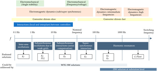
Figure 1.
Stability classification according to frequency ranges. The arrows indicate the parameters that can be modified to deal with each phenomenon.
3.2. SW Solutions
In this part, three different SW solutions are presented. Firstly, a supplementary controller was added to the controller to avoid sub-synchronous interactions. This method is called Strategy 1 in this paper. This method is based on state representation that operates continuously, with no specific detection of sub-synchronous interaction. Note that this fact represents an important advantage, given that this is a very fast operation in which the delay added by a detection system is very significant, thereby compromising the damping effectiveness. The state representation consists of the characterization of the sub-synchronous interaction oscillation and the introduction of a counterphase signal opposing to the interaction. However, it is worth noting that if a non-proper tuning is carried out this strategy could represent the passivity erosion at high frequency, thereby increasing the risk of suffering harmonic resonance.
Due to this issue, a holistic design considering the full frequency range is usually the best alternative. For this purpose, a heuristic algorithm (e.g., genetic algorithm) can be employed to determine the proper tuning of the state-feedback controller. Moreover, as part of the optimization, other controller gains could be also considered. This is the case of the current controller gains acting on the feedback term. The objective function or fitness is a combination of different stability indexes. Concretely, this is minimum damping, maximum sensibility, and a passivity index. The minimum damping should be maximized in order to enhance stability margins. Considering that a controller can be stable but with a poor robustness, the maximum sensibility needs to be minimized. Finally, to avoid converter-driven stability issues, an index regarding passivity must be included. This index could be related to the angle or the conductance of the equivalent impedance. A second strategy was added to control negative sequences and to avoid sub-synchronous interactions, and it is based on robust criteria. In the third strategy, a virtual admittance is added to the control system to shape the impedance and achieve passivity for a specified range of frequencies.
Figure 2 compares the angle of the impedance of a standard controller and three strategies. Strategy 1 and Strategy 3 show that the angle does not significantly differ from the standard controller, while Strategy 2 shows an improvement in stability over 600 Hz.
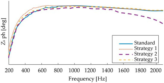
Figure 2.
Impedance angle comparison. Angle values hidden from the y axis for confidentiality.
Figure 3 shows the effectiveness of each strategy compared to a standard controller, with no positive sub-synchronous damping when a SSCI event exists on the grid. All strategies are shown to be equivalent in terms of their effectiveness.
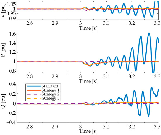
Figure 3.
Effectiveness of each strategy against SSCI events.
In addition to this control modification, there are other actions that contribute to further passivity improvements. Firstly, control delays must be reduced or compensated as much as possible. In this regard, antialiasing filter parametrization has been reviewed. Moreover, an additional controller, acting on the feedforward term, has been incorporated, providing an additional degree of freedom. The adopted solution is similar to the one discussed in [26]. In summary, impedance shaping is conducted thanks to the addition of an equivalent virtual impedance. The aim of this controller is to guarantee that WTG impedance is purely resistive at the resonance frequency encountered in the grid.
4. Plant Solutions
4.1. General Overview
When the WTGs are installed in a power plant, the harmonic standards and the passivity criteria need to be met at the PCC. Therefore, the characteristics of the power plant components need to be considered. In this sense, wind plants in which the internal lines and transformers have a predominantly resistive behavior improve the passivity of the plant. In other words, in the case that the WT does not have passivity, the general behavior of the wind plant could be passive. However, predominantly reactive plants do not sufficiently attenuate this effect. In fact, plants with long lines can result in resonant effects between the turbines and line capacities that lead to non-passive behavior, such as the one shown in Figure 4, where the phases at harmonics of 20 and 21 (1000 Hz and 1050 Hz) are outside the passivity limits of ±90°. It is common in the substations of wind plants to have C-Type harmonic filters, such as the one shown in Figure 5. In addition to the improvement in the wind plant passivity, the capacitor C1,PCC can be used in a C-Type filter to deliver reactive power to the PCC, thereby compensating for the inductance of the power plant lines. This compensation allows the wind turbines to operate at a power factor closer to 1 while the power plant meets the compliance requirements of the power factor. Given that the wind turbines operate at a power factor closer to 1, their voltage support capability is increased.
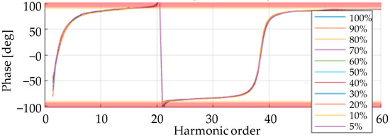
Figure 4.
Impedance angle of an extensive wind power plant with the turbines operating at different power levels (see legend). Red areas represent non-passive characteristics.
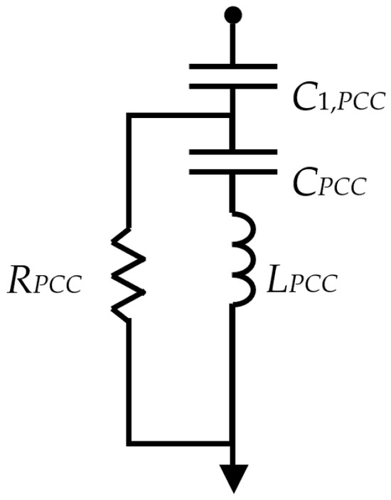
Figure 5.
Filter considered at plant level: C-Type filter at the PCC.
4.2. Methodology for Filter Design
In this section, a method of sizing C-Type filters is proposed so that, in addition to their original functions, they contribute to the passivity of the plant.
The impedance of the C-Type filter shown in Figure 5 is:
First, C1 is calculated. Given that C and L are computed to resonate at the fundamental frequency (), the reactive power is given by C1. Therefore, C1 can be computed in p.u. as follows:
where yC1 is the admittance of the capacitor in p.u., and qd is the desired reactive power for the compensation, also in p.u.
Next, the rest of the filter components are designed so that the total reactance of the filter at the tuned frequency () is 0. Applying the method described in [29], the following relationships that define the remaining filter components are found; q is the filter quality factor:
4.3. Application to a Case Study
The above design methodology is applied to the design of a C-Type filter, for star connection in the PCC of a wind plant with 15 turbines of 6 MW each, giving rise to a nominal power in the PPC of the wind power plant MW. The voltage of the plant is kV. The filter should have a quality factor q = 2, provide a reactive power , and be tuned for the thrird harmonic (). Therefore, the elements required for the C-Type filter are:
Figure 6 shows the impedance phase of the plant and the harmonic emission in the PCC after the connection of the filter. As can be seen, the system is passive for all frequencies, and the harmonic emission is below that required by the regulation.
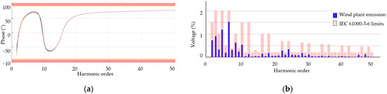
Figure 6.
Behavior of a wind power plant with a C-Type filter connected at the PPC: (a) impedance angle, with red areas representing non-passive characteristics.; (b) harmonic emission.
5. Trade-Off Analysis
This section provides a realistic analysis of the three options described in this paper for a 15-turbine, 90 MW wind plant. The options analyzed are the SW-based solution described in III. B, and the design of a plant-level C-Type filter described in IV. B. For each of these options, an analysis of the potential benefit and limitations, as well as the associated costs, is presented, so that the user can choose the most appropriate option according to their needs. The main results are summarized in Table 2.
Table 2.
Main results of the trade-off analysis.
On the one hand, the SW-based solution has a capital advantage, which is its lack of implementation cost. Each SW-based solution is currently available in the controller and is considered to be amortized. No extra cost per turbine is required.
The sub-synchronous resonance problems are eliminated with SW-based solutions, although they can cause the loss of passivity at frequencies close to the 20th harmonic, since the cut-off frequency of the control loops is not high enough.
On the other hand, the C-Type filter solution at the plant level, as described in Section 4.2, has two advantages over the filters located in each turbine. On the one hand, no additional element is required in the nacelle, thereby reducing the heat generation inside the nacelle and its cost. Moreover, this filter can be used to compensate for the reactive power of the wind plant power lines, improving the power factor provided in the PCC, and the maintenance is simplified, given that the plant substation is easier to access than the nacelle of each wind turbine. This solution requires a single filter for the entire 90 MW plant. However, its components must be sized for a voltage of 33 kV. The estimated proportion of the cost of each component of this filter is:
- : 10–15%
- (48 mH, 33 kV): 20–30%
- (210 , 33 kV): 15–25%
- : 10–15%
- Switches and protection: 20–25%
The estimated total cost of the solution is EUR 250,000, which means a cost of 2778 EUR/MW. This estimation is based on the operational experience and could be affected by the layout of the plant; it is representative of a general scenario.
6. Conclusions
The evaluation of the harmonic response in the point of connection is a critical topic to be tackled to increase wind generation when the conventional generation is being reduced. To achieve that, suitable and cost-effective solutions must be developed.
This paper shows that different solutions can be applied to enhance WTG passivity criteria and, hence, reduce the risk of suffering converter-driven stability issues. It has been shown that the passivity and stability criteria are improved by applying SW solutions for low-frequency ranges up to Nyquist frequency. However, passivity and harmonic emission issues cannot be completely removed by means of wind turbine control strategies. In that sense, the incorporation of hardware solutions at the plant level is also analyzed in this paper. The inclusion of a filter at the plant level solves the problems of both harmonic emission and loss of passivity for higher frequency ranges. In this paper, a design methodology for these filters is proposed to show the effectiveness of filters in passivity. The plant-level solution has the additional potential of compensating the reactive power of the power lines, which makes the turbine-level filter the most suitable option.
Author Contributions
Methodology, E.S.-M. and A.B.; Software, M.E.Z. and Ó.C.; Validation, E.S.-M. and D.M.; Formal analysis, M.E.Z.; Investigation, E.S.-M. and A.B.; Resources, A.M.B.; Data curation, Ó.C.; Writing – original draft, E.S.-M. and A.B.; Writing – review & editing, M.E.Z., D.M. and P.S.; Visualization, D.M., Ó.C. and A.B.; Supervision, A.M.B., A.U. and P.S.; Project administration, A.M.B. and P.S.; Funding acquisition, A.M.B., A.U. and P.S.. All authors have read and agreed to the published version of the manuscript.
Funding
This work was funded by the Government of Navarre under Grant 0011-1411-2022-000049 through EnVeNA Project and by grant PID2022-139914OB-I00 funded by MICIU/AEI/10.13039/501100011033/ (Spain) and by ERDF/EU (European Union).
Institutional Review Board Statement
The figures and values presented in this paper should not be used to judge the performance of Siemens Gamesa (SGRE) technology as they are solely presented for demonstration purposes. Any opinions or analyses contained in this paper are the opinions of the authors and are not necessarily the same as those of SGRE.
Data Availability Statement
The original contributions presented in this study are included in the article. Further inquiries can be directed to the corresponding authors.
Conflicts of Interest
The authors declare no conflict of interest.
References
- Kundur, P. Power System Stability; McGraw-Hill Inc.: New York, NY, USA, 1994. [Google Scholar]
- Hatziargyriou, N.; Milanovic, J.; Rahmann, C.; Ajjarapu, V.; Canizares, C.; Erlich, I.; Hill, D.; Hiskens, I.; Kamwa, I.; Pal, B.; et al. Definition and Classification of Power System Stability—Revisited & Extended. IEEE Trans. Power Syst. 2021, 36, 3271–3281. [Google Scholar]
- Bose, B.K. Power Electronics, Smart Grid, and Renewable Energy Systems. Proc. IEEE 2017, 105, 2011–2018. [Google Scholar] [CrossRef]
- Sacristán, J.; Goñi, N.; Berrueta, A.; López, J.; Rodríguez, J.L.; Ursúa, A.; Sanchis, P. Inertial Response and Inertia Emulation in DFIG and PMSG Wind Turbines: Emulating Inertia from a Supercapacitor-based Energy Storage System. In Proceedings of the EEEIC/I and CPS Europe, Bari, Italy, 7–10 September 2021. [Google Scholar] [CrossRef]
- Berrueta, A.; Sacristán, J.; López, J.; Rodríguez, J.L.; Ursúa, A.; Sanchis, P. Inclusion of a Supercapacitor Energy Storage System in DFIG and Full-Converter PMSG Wind Turbines for Inertia Emulation. IEEE Trans. Ind. App. 2023, 59, 3754–3763. [Google Scholar] [CrossRef]
- Jie, H.; Zhao, Z.; Zeng, Y.; Chang, Y.; Fan, F.; Wang, C.; See, K.Y. A review of intentional electromagnetic interference in power electronics: Conducted and radiated susceptibility. IET Power Electron. 2024, 17, 1487–1506. [Google Scholar] [CrossRef]
- Shair, J.; Li, H.; Hu, J.; Xie, X. Power system stability issues, classifications and research prospects in the context of high-penetration of renewables and power electronics. Renew. Sustain. Energy Rev. 2021, 145, 111111. [Google Scholar] [CrossRef]
- Kong, L.; Xue, Y.; Qiao, L.; Wang, F. Review of Small-Signal Converter-Driven Stability Issues in Power Systems. IEEE Open Access J. Power Energy 2022, 9, 29–41. [Google Scholar] [CrossRef]
- Singh, A.; Debusschere, V.; Hadjsaid, N.; Legrand, X.; Bouzigon, B. Slow-Interaction Converter-Driven Stability in the Distribution Grid: Small-Signal Stability Analysis With Grid-Following and Grid-Forming Inverters. IEEE Trans. Power Syst. 2024, 39, 4521–4536. [Google Scholar] [CrossRef]
- Ghimire, S.; Kkuni, K.V.; Guerreiro, G.M.G.; Guest, E.D.; Jensen, K.H.; Yang, G. Oscillations between Grid-Forming Converters in Weakly Connected Offshore WPPs. In Proceedings of the 2024 IEEE Power & Energy Society General Meeting (PESGM), Seattle, WA, USA, 21–25 July 2024; pp. 1–5. [Google Scholar] [CrossRef]
- Ma, H.T.; Brogan, P.B.; Jensen, K.H.; Nelson, R.J. Sub-Synchronous Control Interaction studies between full-converter wind turbines and series-compensated AC transmission lines. In Proceedings of the 2012 IEEE Power and Energy Society General Meeting, San Diego, CA, USA, 22–26 July 2012; pp. 1–5. [Google Scholar] [CrossRef]
- Liu, H.; Xie, X.; He, J.; Xu, T.; Yu, Z.; Wang, C.; Zhang, C. Subsynchronous Interaction Between Direct-Drive PMSG Based Wind Farms and Weak AC Networks. IEEE Trans. Power Syst. 2017, 32, 4708–4720. [Google Scholar] [CrossRef]
- Australian Energy Market Operator Limited. System Strength in the NEM explainded. Available online: https://aemo.com.au/-/media/files/electricity/nem/system-strength-explained.pdf (accessed on 2 May 2025).
- Cheng, Y.; Fan, L.; Rose, J.; Huang, S.-H.; Schmall, J.; Wang, X.; Xie, X.; Shair, J.; Ramamurthy, J.R.; Modi, N.; et al. Real-World Subsynchronous Oscillation Events in Power Grids With High Penetrations of Inverter-Based Resources. IEEE Trans. Power Syst. 2023, 38, 316–330. [Google Scholar] [CrossRef]
- IEEE Std 1204-1997; IEEE Guide for Planning DC Link Terminating at AC Locations Having Low Short-Circuit Capacities. Institute of Electrical and Electronics Engineers (IEEE): Piscataway, NJ, USA, 1997.
- Bengtsson, T.; Roxenborg, S.; Saha, M.M.; Lindström, P.-O.; Eriksson, H.; Lindström, M. Case studies and experiences with Sub-synchronous resonance (SSR) detection technique. In Proceedings of the 2016 Power Systems Computation Conference (PSCC), Genoa, Italy, 20–24 June 2016; pp. 1–6. [Google Scholar] [CrossRef]
- Zhou, J.Z.; Ding, H.; Fan, S.; Zhang, Y.; Gole, A.M. Impact of Short-Circuit Ration and Pahse-Locked-Loop Parameters on the Small-Signal Behaviour of a VSC-HVDC Converter. IEEE Trans. Power Deliv. 2014, 29, 2287–2296. [Google Scholar] [CrossRef]
- Fan, L.; Miao, Z. Wind in weak grids: 4 Hz or 30 Hz oscillations? IEEE Trans. Power Syst. 2018, 33, 5803–5804. [Google Scholar] [CrossRef]
- Mohammed, N.; Udawatte, H.; Zhou, W.; Hill, D.J.; Bahrani, B. Grid-Forming Inverters: A Comparative Study of Different Control Strategies in Frequency and Time Domains. IEEE Open J. Ind. Electron. Soc. 2024, 5, 185–214. [Google Scholar] [CrossRef]
- Mitsugi, Y.; Baba, J. Analysis of Subsynchronous Control Interaction of a Grid Forming Inverter. In Proceedings of the 2024 IEEE Power & Energy Society General Meeting (PESGM), Seattle, WA, USA, 21–25 July 2024; pp. 1–5. [Google Scholar] [CrossRef]
- Gu, K.; Wu, F.; Zhang, X.-P.; Ju, P.; Zhou, H.; Luo, J.; Li, J. SSR Analysis of DFIG-Based Wind Farm With VSM Control Strategy. IEEE Access 2019, 7, 118702–118711. [Google Scholar] [CrossRef]
- IEC 61400-21-1; Wind Energy Generation Systems—Part 21-1: Measurement and Assessment of Electrical Characteristics—Wind Turbines. International Electrotechnical Commission: Geneva, Switzerland, 2019.
- IEEE STD 519; IEEE Standard for Harmonic Control in Electric Power Systems. Institute of Electrical and Electronics Engineers: New York, NY, USA, 2022.
- Bradt, M.; Badrzadeh, B.; Camm, E.; Mueller, D.; Schoene, J.; Siebert, T.; Smith, T.; Starke, M.; Walling, R. Harmonics and resonance issues in wind power plants. In Proceedings of the 2011 IEEE Power and Energy Society General Meeting, Detroit, MI, USA, 24–29 July 2011; pp. 1–8. [Google Scholar] [CrossRef]
- Yin, H.; Sahni, M.; Karnik, N.; Nia, H.K. Root cause analysis for harmonic resonance tripping in wind power plants: An ERCOT case study. In Proceedings of the 2017 IEEE Power & Energy Society General Meeting, Chicago, IL, USA, 16–20 July 2017; pp. 1–5. [Google Scholar] [CrossRef]
- Guest, E.; Jensen, K.H.; Rasmussen, T.W. Mitigation of Harmonic Voltage Amplification in Offshore Wind Power Plants by Wind Turbines With Embedded Active Filters. IEEE Trans. Sustain. Energy 2020, 11, 785–794. [Google Scholar] [CrossRef]
- Harnefors, L.; Wang, X.; Yepes, A.G.; Blaabjerg, F. Passivity-Based Stability Assessment of Grid-Connected VSCs—An Overview. IEEE J. Emerg. Sel. Top. Power Electron. 2016, 4, 116–125. [Google Scholar] [CrossRef]
- Harnefors, L.; Yepes, A.G.; Vidal, A.; Doval-Gandoy, J. Passivity-Based Stabilization of Resonant Current Controllers with Consideration of Time Delay. IEEE Trans. Power Electron. 2014, 29, 6260–6263. [Google Scholar] [CrossRef]
- Xiao, Y.; Zhao, J.; Mao, S. Theory for the design of C-type filter. In Proceedings of the 11th International Conference on Harmonics and Quality of Power (IEEE Cat. No.04EX951), Lake Placid, NY, USA, 12–15 September 2004; pp. 11–15. [Google Scholar] [CrossRef]
Disclaimer/Publisher’s Note: The statements, opinions and data contained in all publications are solely those of the individual author(s) and contributor(s) and not of MDPI and/or the editor(s). MDPI and/or the editor(s) disclaim responsibility for any injury to people or property resulting from any ideas, methods, instructions or products referred to in the content. |
© 2025 by the authors. Licensee MDPI, Basel, Switzerland. This article is an open access article distributed under the terms and conditions of the Creative Commons Attribution (CC BY) license (https://creativecommons.org/licenses/by/4.0/).