Article

Performance Analysis of a Novel Hybrid Ejector Refrigeration System Driven by Medium- to High-Temperature Industrial Waste Heat

Beijing Research Center of Sustainable Energy and Buildings, Beijing University of Civil Engineering and Architecture, Beijing 100044, China
*
Author to whom correspondence should be addressed.
Energies 2025, 18(11), 2706; https://doi.org/10.3390/en18112706
Submission received: 27 March 2025 / Revised: 10 May 2025 / Accepted: 19 May 2025 / Published: 23 May 2025
(This article belongs to the Section B: Energy and Environment)

Abstract

:
The thermally driven ejector refrigeration system is generally used to recover industrial waste heat to improve the energy efficiency of industrial processes. However, for conventional single-stage ejector refrigeration systems (ERSs), the higher-pressure steam derived from high-temperature waste heat elevates the primary fluid pressure, resulting in significant pressure mismatch with the secondary fluid, which consequently leads to large irreversible losses and substantial degradation in system performance. To address this issue, a novel hybrid ejector refrigeration system (NHERS) is proposed and analyzed under design and off-design conditions using thermodynamics. The results indicate that under design conditions, compared to the conventional single-stage ejector refrigeration system, the proposed hybrid ejector refrigeration system can achieve increases of about 20.6% in the entrainment ratio, around 15.2% in the coefficient of performance (COP), and about 21.4% in exergetic efficiency. Analyzing its performance under off-design conditions to provide technical solutions for the flexible operation of the hybrid ejector refrigeration system proposed in this paper can broaden its application scenarios. Consequently, the proposed NHERS demonstrates remarkable superiority in energy conversion and transfer processes, showing certain application prospects in the field of medium- to high-temperature industrial waste heat recovery.

1. Introduction

As a major industrial producer, China’s industrial energy consumption accounts for approximately 70% of total energy consumption, making industrial energy conservation a critical pathway to achieving the goals of carbon peaking and carbon neutrality [1]. At present, industrial waste heat recovery has become an effective approach for industrial energy conservation.
Major energy-intensive enterprises, such as chemical, petroleum, and metallurgical industries, generate substantial amounts of waste heat during production processes, yet these valuable thermal resources remain underutilized to a certain extent, especially in the case of medium- to high-temperature waste heat [2,3]. These energy-intensive enterprises consume substantial quantities of chilled water during the recovery processes of chemical byproducts. Thermally driven refrigeration equipment can efficiently harness industrial waste heat and simultaneously produce the chilled water required for the recovery process of chemical byproducts. The application of this technology offers a dual advantage: it significantly improves the energy efficiency of energy-intensive processes and correspondingly reduces carbon emissions.
In general, high-temperature industrial waste heat is recovered to generate medium-pressure steam, a portion of which is used to drive thermally driven absorption and ejector refrigeration systems for producing chilled water [4,5]. The absorption refrigeration system (ARS) is characterized by a higher coefficient of performance (COP), large physical dimensions, a high initial cost, and a high maintenance workload [6,7]. Compared with the ARS, the ejector refrigeration system (ERS) has a lower COP, smaller physical dimensions, a lower initial cost, and a lower maintenance workload [8,9,10]. It must be pointed out that most industrial enterprises feature compact spatial layouts with limited surplus space. Thus, ejector refrigeration systems are commonly used in the field of industrial waste heat [11]. A disadvantage of ERS is that when directly utilizing medium-pressure steam, they may experience reduced cooling performance and fail to achieve optimal refrigeration efficiency [12]. If a pressure-reducing valve is utilized to adjust the steam pressure for ERS operation, it would result in significant exergy destruction during the throttling process, thereby degrading both energy quantity and quality utilization efficiency.
To enhance the performance of the ERS, many researchers have conducted studies on aspects such as ejector operational mechanisms, refrigeration system optimization, operating parameters, and primary refrigerant fluids [13]. For specific refrigeration conditions, the performance of the ERS depends on ejector performance.
Munday et al. [14,15,16] theoretically demonstrated that ejector operations can be categorized into critical, subcritical, and counterflow regimes. The critical regime corresponds to a specific state point where the entrainment ratio, temperature, and pressure reach the threshold values. At this critical point, the refrigeration performance of the ERS attains its maximum.
Selvaraju et al. [17] established an experimental platform for the ERS and tested the ejector’s performance under different generation, evaporation, and condensation temperatures. The results indicated that the entrainment ratio first increased and then decreased with a rising generation temperature, continuously increased with a higher evaporation temperature, and remained constant as the condensation temperature increased until the critical point, after which it dropped sharply. The study also noted that the refrigeration capacity and COP trends of the ERS are aligned with those of the ejector’s performance. Selvaraju and Mani [18] investigated the effects of varying generation temperatures on the performance of an ERS with R134a under fixed operating conditions, specifically constant condensation and evaporation temperatures. The results showed that an optimal generation temperature exists when the system achieves maximum performance. Ma et al. [19] investigated the variation patterns of system refrigeration capacity and COP with generation temperature. The experimental results showed that within the range of the tested generation temperature, COP values ranged from 0.17 to 0.32.
Anan et al. [20] analyzed the performance of four refrigerants—R1234yf, R134a, R290, and R600a—in single-stage and two-stage ERS configurations. They found that two-stage ERSs consistently outperformed single-stage systems, regardless of the refrigerant utilized. Yu et al. [21] cascaded an additional ejector downstream of the primary ejector in the ERS, utilizing the mixed fluid from the primary ejector as the secondary fluid for the secondary ejector and sourcing the secondary ejector’s primary fluid from the pressurized fluid at the condenser outlet. The results indicated that this system effectively improved refrigeration performance when using higher-temperature heat sources and reduced input exergy by 16–23%.
Liang et al. [10] proposed a two-stage dual-temperature ejector refrigeration cycle to address the problem of a low entrainment ratio in single-stage ejector refrigeration systems operating under high condensing temperatures or low evaporating temperatures, which makes it difficult to meet dual-temperature refrigeration requirements (such as 0 °C for cold storage and −25 °C for freezing). Driven by waste heat from exhaust gas, this cycle achieves stepwise pressure boosting through the series connection of two-stage ejectors, overcoming the high-pressure ratio limitation of single-stage ejectors and improving overall system performance.
Dai et al. [22] proposed a new two-stage ejector refrigeration cycle that effectively improves the COP and entrainment ratio, reduces the compression ratio, and enhances energy utilization efficiency by means of stage-by-stage pressure boosting and separating high- and low-boiling-point refrigerants using a gas–liquid separator. It demonstrates significant advantages, especially under harsh working conditions such as low-temperature evaporation, high-temperature condensation, and low-grade heat sources.
Megdouli et al. [23] proposed an innovative two-stage, two-temperature ejector cycle, which utilizes waste heat from engine exhaust gases to simultaneously achieve power generation and refrigeration. An artificial neural network surrogate model was developed to predict the performance of the ejector, simplifying complex calculations. The study shows that this system significantly reduces exergy losses, improves the COP, and balances economic efficiency.
Bellos et al. [24] simultaneously optimized both the ejector design and generation temperature, comparing the performance of five refrigerants—R123, R134a, R141b, R245fa, and R600a—in the ejector refrigeration system. The results indicated that R141b demonstrated the highest performance, achieving a peak COP of 0.397, followed by R123, R245fa, R600a, and R134a in descending order. Chen et al. [25] investigated the performance differences between single-stage and two-stage ejectors using R141b as the working fluid, introducing the compression ratio of equivalent entrainment ratio as a key criterion. Their study revealed that single-stage ejectors are suitable for scenarios with low compression ratios and stable operating conditions, while two-stage ejectors exhibit superior performance under high compression ratios and variable operating conditions, particularly demonstrating significant advantages in refrigeration systems using R141b as the working fluid.
Although extensive research has been conducted on ERSs, medium-pressure steam derived from medium- to high-temperature industrial waste heat remains inefficiently utilized in conventional ejector refrigeration systems. To address this issue, a novel hybrid ejector refrigeration system (NHERS) with R141b driven by medium- to high-temperature industrial waste heat is proposed, and it is analyzed from the perspective of the first and second laws of thermodynamics in the following sections.

2. Materials and Methods

2.1. System Description

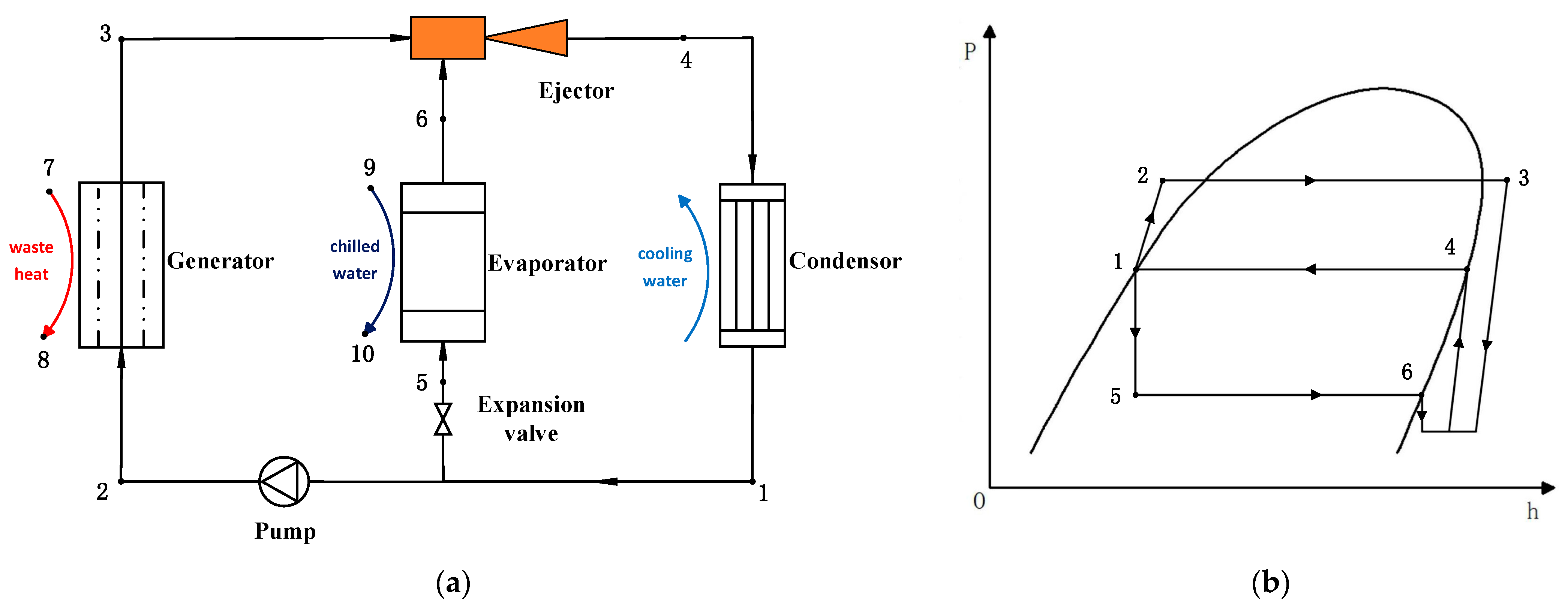
2.1.1. Conventional Single-Stage ERS

The schematic diagram and pressure enthalpy diagram of the conventional single-stage ERS are shown in Figure 1. It consists of an ejector, generator, evaporator, condenser, pump, and expansion valve.
The entire working process is expressed as follows: When the generator is heated, the high-temperature and high-pressure refrigerant is generated to act as the primary fluid, which then enters the ejector. The refrigerant from the evaporator is entrained into the ejector as the secondary fluid. The primary fluid and the secondary fluid are mixed within the mixing chamber. As a result, the refrigerant in the evaporator is evaporated, thereby generating cooling capacity. After that, the mixed fluid is pressurized in the diffuser and then enters the condenser, where it is condensed into a liquid. The condensed liquid is split into two streams. One stream passes through the expansion valve and enters the evaporator. The other stream is pumped back to the generator by the circulating refrigerant pump. In this manner, a complete ejector refrigeration cycle is established.

2.1.2. Proposed NHERS

The proposed NHERS mainly comprises a hybrid ejector module, generator, evaporator, condenser, pump, and two expansion valves. The hybrid ejector module is composed of a primary ejector, a secondary ejector, and an expansion valve (2). The schematic diagram and pressure enthalpy diagram of the proposed NHERS are shown in Figure 2.
The working principle of the system is illustrated as follows:
  • Generator Exergy Transfer: The liquid refrigerant from the condenser (state point 1) is pressurized by the refrigerant pump (state point 2) and heated by medium-pressure steam in the generator, where it vaporizes into superheated vapor (state point 3);
  • Primary Ejector Mixing: The superheated refrigerant vapor from the generator serves as the primary fluid for the primary ejector, which entrains the refrigerant from the secondary ejector outlet (state point 8). The two streams are mixed within the primary ejector;
  • Secondary Ejector Mixing: The refrigerant from the primary ejector (state point 4) acts as the primary fluid for the secondary ejector, entraining the low-pressure refrigerant vapor from the evaporator (state point 7) and the two streams mixing again within the secondary ejector;
  • Split of the Mixed Fluid: The refrigerant vapor from the secondary ejector (state point 5) splits into two streams: one stream returns to the primary ejector as secondary fluid, while the other steam enters the condenser, where it is condensed into liquid refrigerant (state point 1) by cooling water;
  • Split of Liquid Refrigerant from Condenser: The liquid refrigerant from the condenser is also divided into two streams: one stream flows through the expansion valve to the evaporator, taking heat away from chilled water (state point 6), and the other stream is pressurized by the pump and fed to the generator (state point 2). This completes the refrigeration cycle.

2.2. Thermodynamic Model

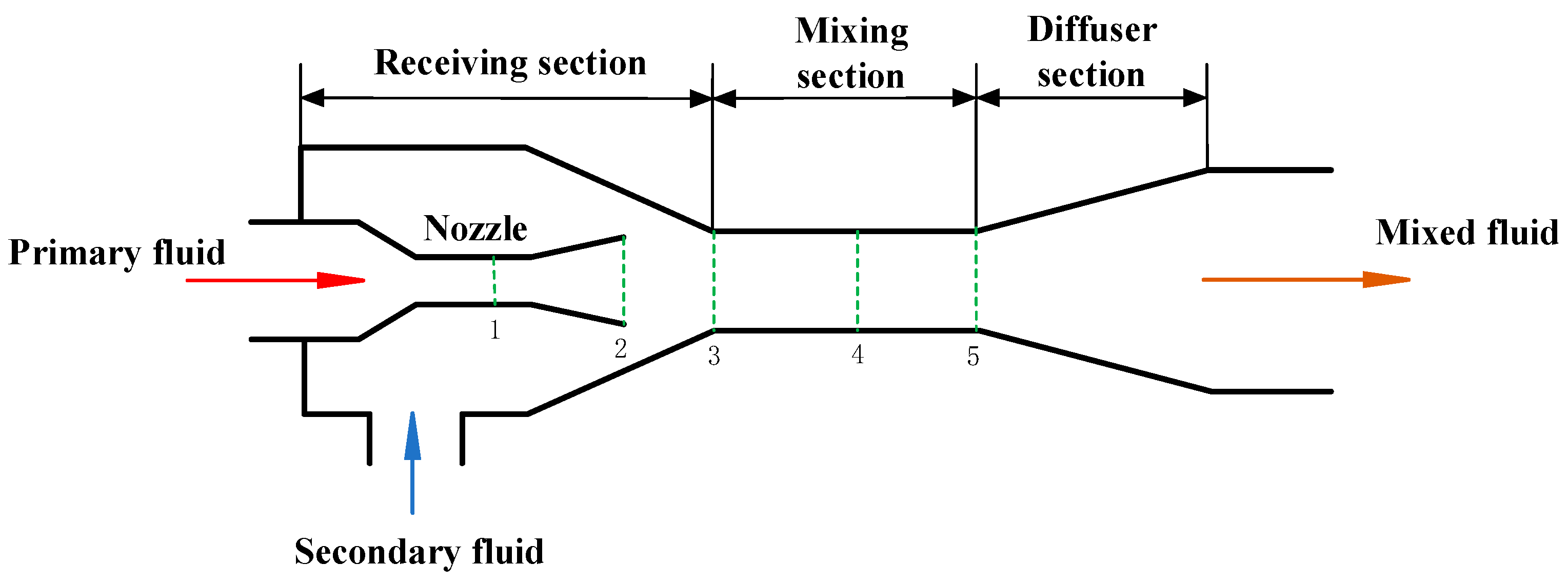
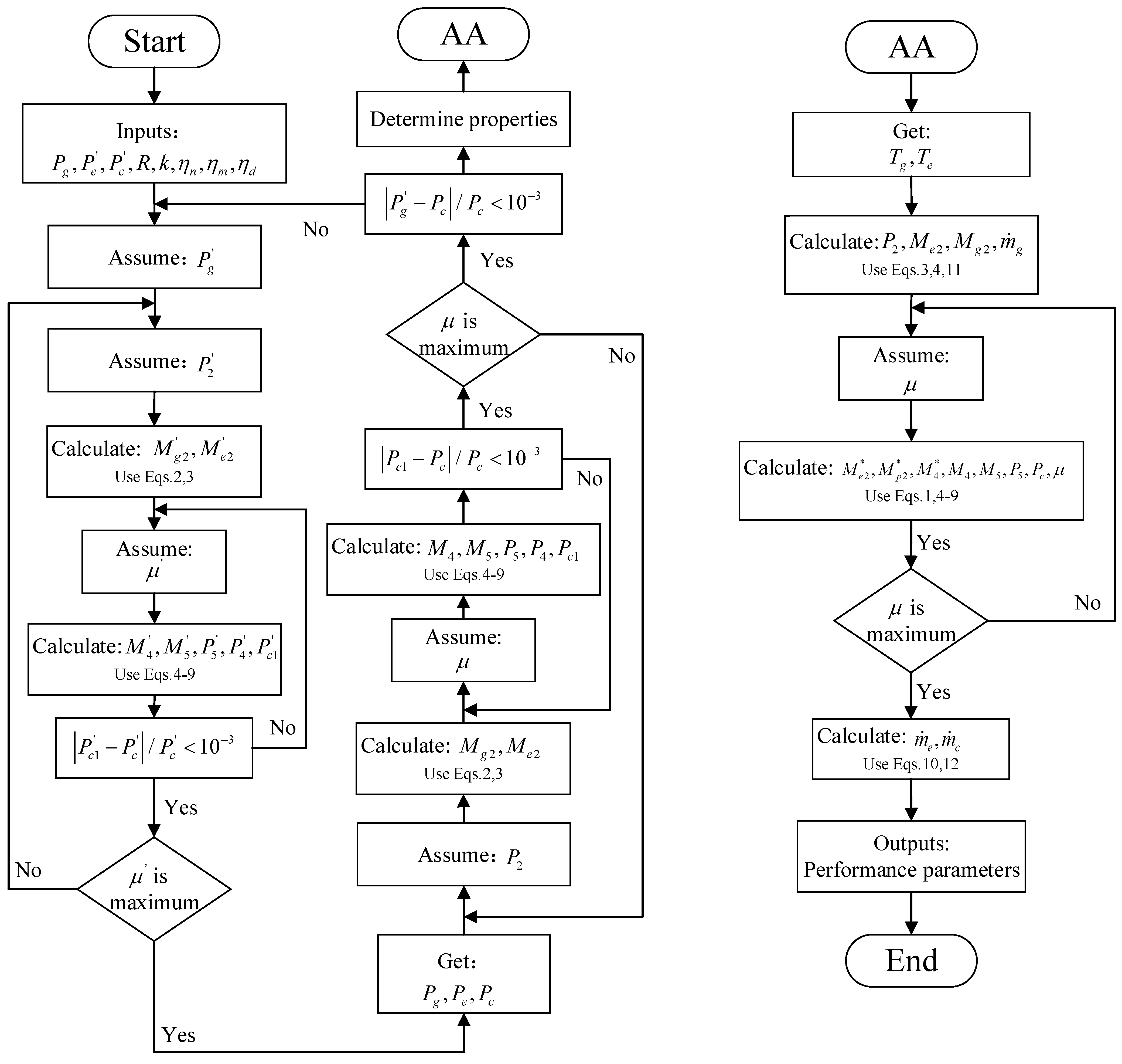
2.2.1. Ejector Model

The classical thermodynamic model of ejectors is characterized by their simplicity and clarity, and it is relatively convenient for calculation and application. Given these advantages, in the research and analysis of ejectors in this paper, the classical thermodynamic model with isentropic correction [26] will be adopted, and Engineering Equation Solver (EES) will be used for simulation calculations to explore and analyze relevant issues.
The ejector is the key component of the ejector refrigeration system, and its structure diagram is illustrated in Figure 3. The ejector is mainly made up of four main components: nozzle, receiving section, mixing section, and diffuser section. To simplify the model, the following assumptions are made:
  • The fluids in the ejector are all saturated gases. The gas flow process is adiabatic and isentropic, and the initial velocities of the primary fluid and the secondary fluid are neglected;
  • The refrigerant vapor in the ejector is regarded as an ideal gas, and the adiabatic expansion index can vary;
  • Frictional losses within the ejector are defined by the nozzle efficiency η n , mixing efficiency η m , and diffuser efficiency η d . In this paper, the nozzle efficiency, mixing efficiency, and diffuser efficiency are set to 0.85, 0.85, and 0.95, respectively;
  • The ejector is one-dimensional, with steady-state flow conditions.
Based on the above assumptions, the computational model of the ejector is presented below.
  • Entrainment ratio:
μ = m ˙ e m ˙ g
In this equation, m ˙ e represents the mass flow rate of the secondary fluid, and m ˙ g denotes the mass flow rate of the primary fluid. For the NHERS, the entrainment ratio of the hybrid ejector module is defined as the ratio of the mass flow rate of the secondary fluid entering the module from the evaporator to that of the primary fluid entering the module from the generator.
  • The Mach number of the primary fluid at section 2:
M g 2 = 2 η n k 1 p g p 2 k 1 k 1
In this equation, P g represents the pressure of the primary fluid, P 2 denotes the pressure at section 2, and k is the adiabatic index of the cross-section where the fluid is located ( k = C p / C v ), where C p is the specific heat capacity at constant pressure and C v is the specific heat capacity at constant volume.
  • The Mach number of the secondary fluid at section 2:
M e 2 = 2 k 1 p g p 2 k 1 k 1
  • The critical Mach number of the mixture at section 4:
M 4 * = η m M g 2 * + μ M e 2 * T e / T g 1 + μ 1 + μ T e T g
where T g is temperature of the primary fluid and T e is the temperature of the secondary fluid.
  • Relationship between actual Mach number and critical Mach number:
M * = M 2 k + 1 M 2 k 1 + 2
  • The Mach number of the hybrid fluid at section 5:
M 5 = M 4 2 + 2 k 1 M 4 2 2 k k 1 1
  • Pressure rise of the hybrid fluid after the shock wave:
p 5 p 4 = 1 + k M 4 2 1 + k M 5 2
  • Pressures in sections 2, 3, and 4 are equal:
p 2 = p 3 = p 4
  • Back pressure of ejector:
p c p 5 = η d ( k 1 ) 2 M 5 + 1 k k 1

2.2.2. Models of Other System Components

The calculation of thermodynamic parameters for other components can be performed based on the law of energy conservation by making the following assumptions to establish a thermodynamic model of the hybrid ejector refrigeration system:
  • During operation, the system continuously maintains stable and continuous operating conditions;
  • The heat losses and superheat in the heat transfer processes of the evaporator, generator, and condenser are neglected, and it is assumed that the fluids at their outlets are all in saturated states;
  • The heat and pressure losses of the refrigerant during pipeline flow are neglected.
  • Evaporator cooling capacity:
Q e = m ˙ g h 7 h 6
  • The heat input to the generator:
Q g = m ˙ g h 3 h 2
  • Condenser heat rejection:
Q c = m ˙ c h 5 h 1
  • Pump power consumption:
W p u m p = m ˙ p u m p h 2 h 1
  • Expansion Valve Model:
The throttling of the refrigerant in the expansion valve can be approximated as an isenthalpic process.
h 1 = h 6

2.2.3. Performance Evaluation Model

  • COP of refrigeration cycle systems:
C O P = Q e / Q g + W p u m p
  • According to the definition of exergy, the exergy value of a fluid at a certain state point is as follows [12]:
    E x = m ˙ h h 0 T 0 s s 0
    where m ˙ represents the mass flow rate at the desired state point, and “ h ” and “ s ” denote specific enthalpy and specific entropy, respectively. The subscript “0” indicates the reference state point, where the temperature is 303.15 K and the pressure is 101.325 kPa.
  • The product exergetic efficiency is defined as the ratio of product exergy to input exergy [27]:
η s y s = p r o d u c t   e x e r g y i n p u t   e x e r g y
Exergetic efficiency reflects the degree of effective utilization of energy during the process of transfer and conversion and can be used to judge the comprehensive utilization efficiency of ejector refrigeration systems for waste heat resources.
Table 1 lists the input exergy and the product exergy of the ERS and NHERS.
The detailed solution algorithm for the proposed model is shown in Figure 4. The mathematical model for designing the hybrid ejector refrigeration system is nearly identical to that of the single-stage ejector refrigeration system, with the exception that the system described here requires an iterative solution of two ejectors in series. The second-stage ejector is solved first, followed by the first-stage ejector. Finally, another set of iterations determines the overall performance of the hybrid ejector refrigeration system.

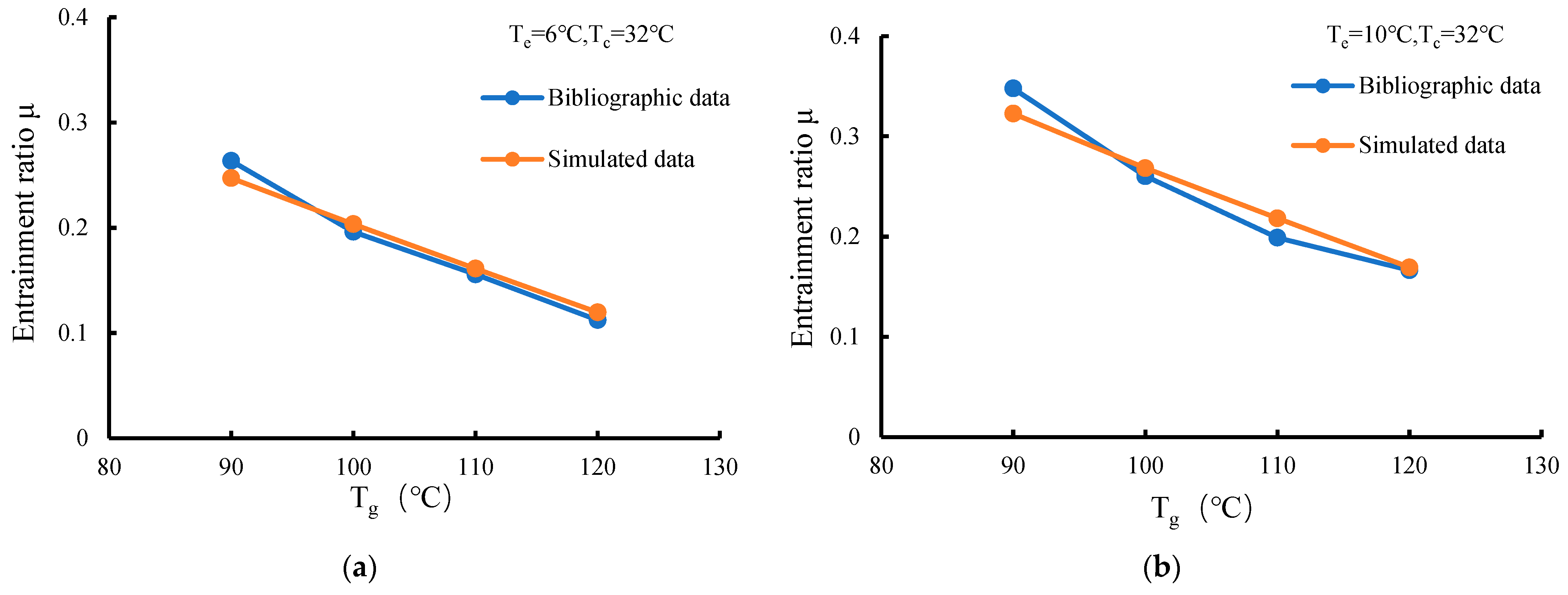
2.3. Model Validation

The simulation results of the single-stage ejector were validated against the experimental results under several operating conditions, listed in Table 2 [28].
The simulated and experimental results of the single-stage ejector are presented in Figure 5. It shows that the maximum discrepancy between experiment and simulation is 9.7%, which fully demonstrates the reliability of the ejector model [29].
From Figure 5, it can also be observed that for a single-stage ejector refrigeration system under certain operating conditions, an excessively high generation temperature leads to a reduction in the entrainment ratio, which consequently decreases the COP of the ejector refrigeration system. If the generation temperature continues to increase, the entrainment ratio of the ejector will further decline, highlighting the limitations of single-stage ejector refrigeration systems at high generation temperatures.

3. Results and Discussion

When the ejector refrigeration system functions as a cooling source, the fluid within the ejector is treated as saturated vapor—as previously noted, even though different refrigerants display distinct pressures at varying temperatures. For a specific refrigerant, the pressure and temperature of its saturated vapor exhibit a unique correlation. Thus, this paper employs the saturation temperature corresponding to the pressure for analysis, a practice that also streamlines integration with practical applications.
In order to scientifically evaluate the performance of the new high-efficiency waste heat recovery system (NHERS) driven by medium- to high-temperature industrial waste heat, it is necessary to conduct a systematic comparative analysis between the NHERS and comparison systems under design conditions to clarify its applicable scenarios. Since the working efficiency of the ejector is extremely sensitive to changes in operating conditions and shows significant fluctuations under different operating condition parameters, it is essential to conduct an in-depth analysis of the operational characteristics of the NHERS under off-design operating conditions. By exploring the operation laws of the system under off-design operating conditions, we can more comprehensively grasp the performance evolution trend of the NHERS when the operating conditions change dynamically, providing an important basis for system optimization and practical applications. Based on the above considerations, the following text presents a detailed analysis of the performance of the NHERS under both design and off-design operating conditions, revealing its operational characteristics from multiple dimensions.

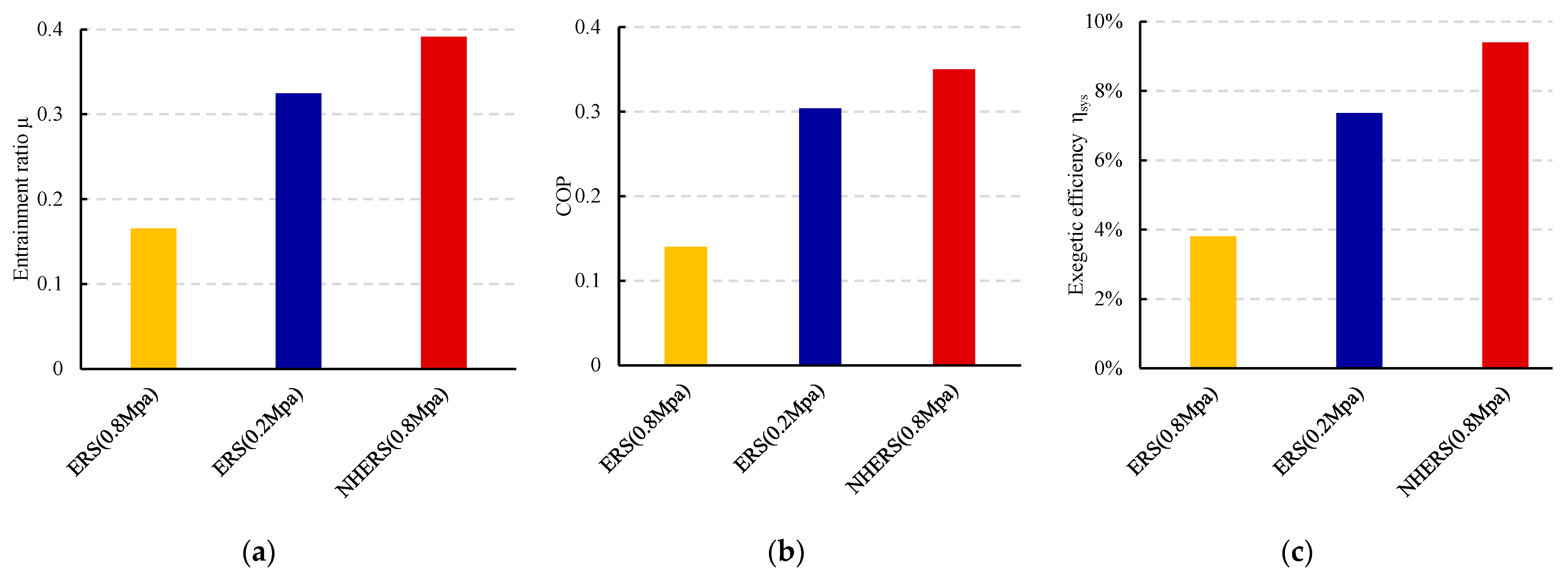
3.1. Performance Under Design Conditions

The steam sourced from medium- to high-temperature industrial waste heat has a pressure of 0.8 MPa, enabling it to reach a generation temperature of 150 °C. For a conventional ERS, under the evaporation temperature and condensation temperature determined in this paper, the generation temperature that can enable it to achieve the optimal refrigeration performance is approximately 100 °C. Therefore, according to the engineering convention, a pressure-reducing valve can be used to reduce the driving steam pressure from 0.8 MPa to 0.2 MPa (100 °C). The design conditions used in this paper are shown in Table 3.
The entrainment ratio, COP, and exergetic efficiency of the proposed NHERS and ERS are shown in Figure 6. The parameters of product exergetic efficiency are listed in Table 4.
As shown in Figure 6, under the design conditions, the ERS (0.8 MPa) exhibits extremely low performance. As previously mentioned, the ERS is unable to efficiently utilize the waste heat steam of high energy level. Compared with the ERS (0.2 MPa), the entrainment ratio, COP, and exergetic efficiency of the proposed NHERS are improved by 20.57%, 15.17%, and 21.69%, respectively.
This is due to the fact that in the proposed NHERS, the primary fluid for the second-stage ejector is made up of both refrigerant from the generator and a portion of refrigerant from the outlet of the second-stage ejector. Thus, the second-stage ejector can draw in more of the secondary fluid—the refrigerant from the evaporator. It must be emphasized that the first-stage ejector is mainly used to recover part of the available energy from the high-pressure refrigerant in the generator and generate more primary fluid for the second-stage ejector. In this way, energy available from the medium-pressure steam is sufficiently utilized by the hybrid ejector module, and the irreversible loss of the proposed NHERS becomes small, while the COP of the proposed NHERS becomes large.

3.2. Performance Under Off-Design Conditions

The effects of different condensation temperatures, generation temperatures, and evaporation temperatures on the refrigeration performance of the proposed NHERS are discussed in the following sections. These operating condition parameters are summarized in Table 5.

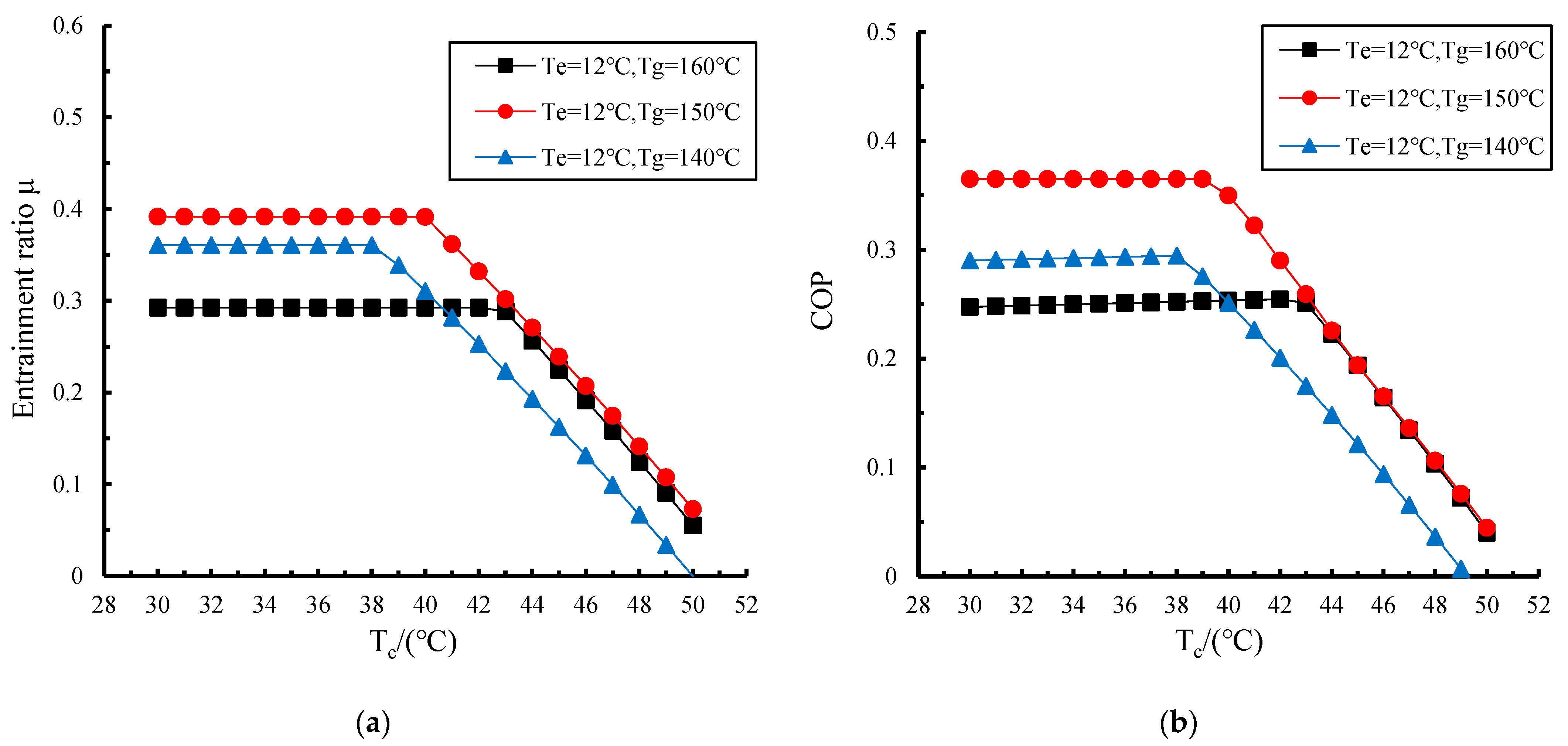
3.2.1. Effects of Condensation Temperature on Performance of Proposed NHERS

The effects of different condensation temperatures on the entrainment ratio of the hybrid ejector module and the system COP are shown in Figure 7.
The condensation temperature critically determines the back pressure of the hybrid ejector module, thereby fundamentally constraining the performance of the ejector under design and off-design conditions. As observed from the figure, initially, both the entrainment ratio and COP remain nearly constant as the condensation temperature increases. However, beyond a certain critical point, these parameters sharply decline.
This phenomenon is attributed to the energy transfer mechanism of the ejector: under given geometric conditions, the energy transferable by the primary fluid has an upper limit. When the back pressure of the hybrid ejector module falls within the critical range, excess energy is dissipated through shock waves in the mixing chamber to maintain system stability. However, once the back pressure exceeds the upper limit, the system must reduce the secondary fluid mass flow rate to match the energy supply. This not only causes the second-stage ejector to entrain less fluid from the evaporator but also results in the first-stage ejector entraining less fluid from the outlet of the second-stage ejector, leading to a reduced entrainment ratio and a subsequent decrease in the COP of the proposed NHERS.
From the comparison of the three operating conditions, it can be concluded that the hybrid ejector module under higher generator temperature can accept a wider back pressure range. This is because as the generator temperature increases, the energy of the working fluid rises, which leads to an increase in the energy of the mixed fluid. Consequently, the ability of the mixed fluid to resist back pressure is enhanced, resulting in a higher corresponding critical pressure value. Therefore, in practical applications, appropriately increasing the primary fluid pressure allows the back pressure to operate within a wider range at maximum performance, which is beneficial for the operational stability of the ejector.

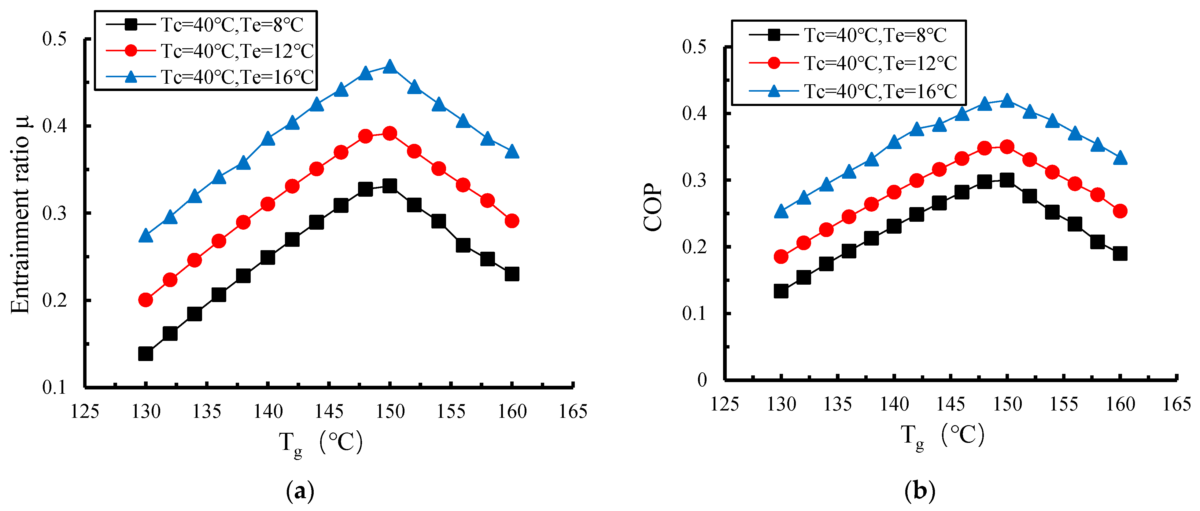
3.2.2. Effects of Generation Temperature on Performance of Proposed NHERS

Maintaining the system’s generation temperature is crucial for its stable operation. However, during actual operation, variations in steam pressure often cause the generation temperature to deviate from that under the design conditions. The effects of different generation temperatures on the entrainment ratio of the hybrid ejector module and the COP are shown in Figure 8.
Figure 8 indicates that variations in the generation temperature have a significant impact on both the entrainment ratio and COP. Within the investigated range of generation temperatures, both the entrainment ratio and COP exhibit a similar trend of first increasing and then decreasing as the generation temperature rises.
This is because as the generation temperature increases, the available energy carried by the primary fluid also gradually increases. A primary fluid with the same mass flow rate can entrain more secondary fluid, thereby enhancing the performance of the ejector. However, when the temperature of the primary fluid continues to increase, the expansion core formed during its passage through the nozzle also enlarges. This enlargement reduces the flow cross-sectional area available for the secondary fluid, leading to a downward trend in the secondary fluid mass flow rate and a subsequent decrease in the COP.
Therefore, increasing the temperature of the primary fluid does not necessarily enhance ejector performance. When heat source parameters deviate from their design values, the ejector’s entrainment ratio decreases. Thus, the generation temperature should be maintained as close as possible to the design conditions to ensure that the ejector operates at its optimal state.

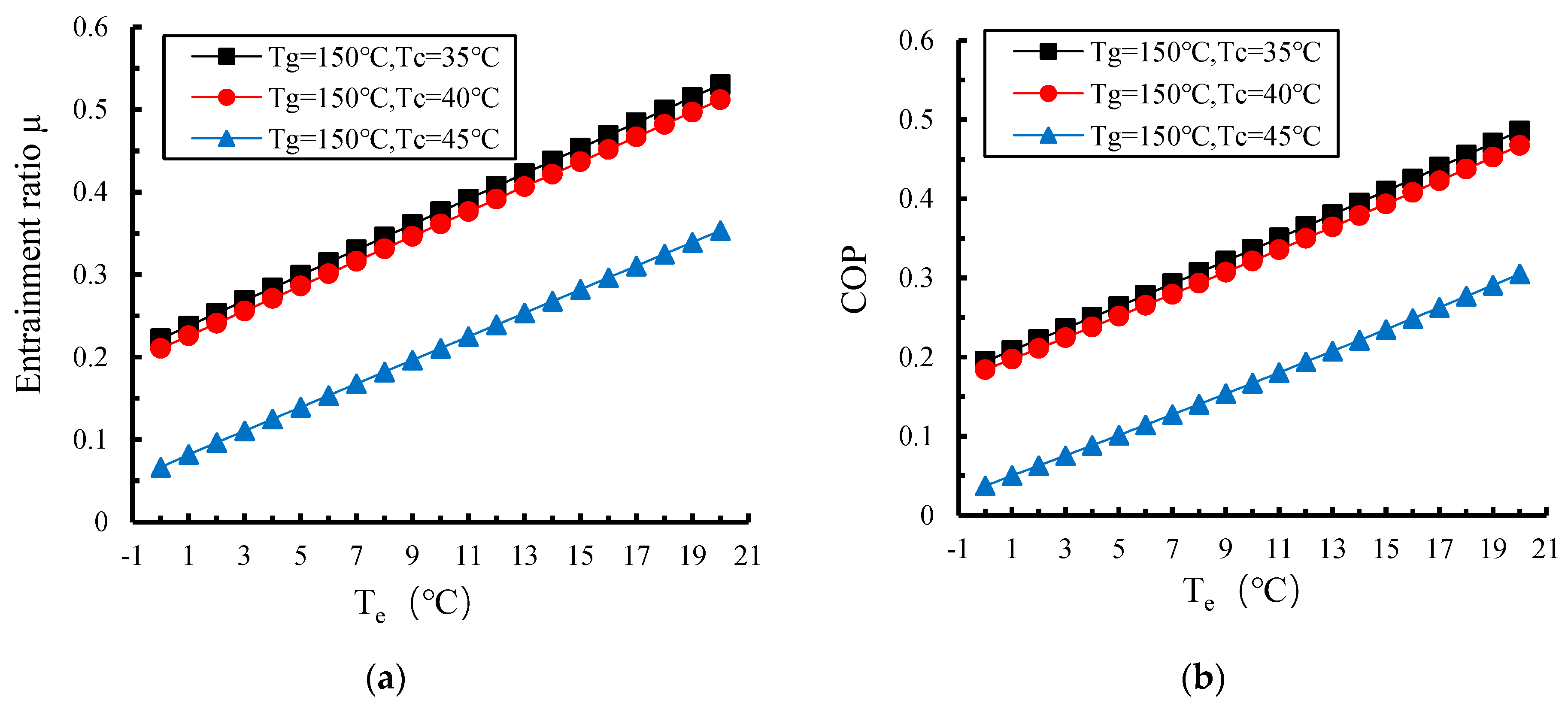
3.2.3. Effects of Evaporation Temperature on Performance of Proposed NHERS

Evaporation temperature is one of the key parameters affecting the performance of ejectors and refrigeration systems. When the refrigeration system load changes, appropriately adjusting the evaporation temperature can effectively regulate the system’s refrigeration capacity. By reasonably controlling the evaporation temperature, the system can maintain efficient operation under different load conditions, thereby enhancing overall refrigeration performance. The effects of different evaporation temperatures on the entrainment ratio of the hybrid ejector module and COP are shown in Figure 9.
Figure 9 illustrates that as the evaporation temperature rises, both the entrainment ratio and COP continuously increase. This is because a higher evaporation temperature contributes to increasing the temperature and pressure of the secondary fluid. On the one hand, this increases the pressure difference between the primary and secondary fluids at the nozzle exit interface, augmenting the driving force for the secondary fluid to enter the ejector suction chamber. On the other hand, the increased energy of the secondary fluid raises the energy of the mixed fluid, enhancing the critical back pressure of the ejector. Consequently, the mass flow rate of the secondary fluid increases.

4. Conclusions

This paper proposes a novel ejector refrigeration cycle system that can efficiently utilize high-temperature industrial waste heat, thereby expanding its applicability to a broader range of scenarios. The conclusions drawn are as follows:
(1)
Compared to the traditional single-stage ejector system, the proposed NHERS integrates two-stage ejector modules in series. While inheriting the advantages of the traditional ejector refrigeration system, such as simple structure, small size, and low cost, increasing the entrainment ratio of the ejector enables a more rational distribution of available energy, significantly reducing irreversible losses in medium- to high-temperature waste heat utilization and enhancing exergetic efficiency.
(2)
Under design conditions, the proposed NHERS demonstrates improved entrainment ratio, COP, and exergetic efficiency to varying degrees. Specifically, the COP can approach 0.35, approximately 1.27 times that of the conventional ERS. Thus, the NHERS would be a better alternative for refrigeration using medium- to high-temperature waste heat steam.
(3)
Performance analysis of the proposed NHERS under off-design conditions indicates that system performance remains stable below the critical condensation temperature range, while the entrainment ratio and COP decline sharply beyond this threshold; increasing the generation temperature raises this critical temperature and enhances system robustness; the entrainment ratio and COP first increase and then decrease with rising generation temperature; dynamic regulation can maintain high efficiency when heat source parameters deviate from design conditions; and raising the evaporation temperature significantly improves refrigeration performance, enabling flexible cooling load matching through evaporation temperature adjustment to meet diverse industrial refrigeration demands.
(4)
This paper is primarily based on theoretical models and simulation analysis. In the future, we will verify the system performance under actual operating conditions through experiments, deploy industrial-grade experimental equipment in industrial waste heat scenarios, and further promote the transformation from theoretical models to engineering applications. Additionally, further investigations can explore the effects of different refrigerants (including environmentally friendly refrigerants like R1234yf, R245fa, or natural refrigerants) on hybrid systems and optimize ejector geometric parameters to achieve broader industrial adaptability.

Author Contributions

Conceptualization, F.S. and C.M.; methodology, F.S.; software, F.S. and C.M.; validation, F.S. and C.M.; formal analysis, F.S.; investigation, Z.W and C.M.; resources, F.S.; data curation, C.M.; writing—original draft preparation, C.M.; writing—review and editing, F.S., C.M. and Z.W.; visualization, C.M. and Z.W.; supervision, F.S.; project administration, F.S.; funding acquisition, F.S. All authors have read and agreed to the published version of the manuscript.

Funding

This research was funded by the Beijing Natural Science Foundation, grant number 322207, and China Scholarship Council, grant number 201909960004.

Data Availability Statement

The original contributions presented in the study are included in the article, further inquiries can be directed to the corresponding author.

Acknowledgments

The authors wish to acknowledge the financial support provided by the Beijing Natural Science Foundation. The China Scholarship Council is also acknowledged for support the visit to the Technical University of Denmark.

Conflicts of Interest

The research was conducted in the absence of any commercial or financial relationships that could be construed as a potential conflict of interest.

Nomenclature

C p [kJ/kg]Specific heat capacity at constant pressure
Cv[kJ/kg]Specific heat capacity at constant volume
Ex[kJ]Exergy
k[-]Adiabatic index
h[kJ/kg]Specific enthalpy
M[-]Mach number
m[kg/s]Mass flow rate
p[kPa]Pressure
Q[kW]Heat flow rate
T[K]Temperature
W[kW]Power
Greek letters
μ[-]Entrainment ratio
η[-]Efficiency
Abbreviations
ERS Ejector refrigeration system
NHERS Novel hybrid ejector refrigeration system
COP Coefficient of performance
ARS Absorption refrigeration system

References

  1. Liu, B.; Jia, M.; Liu, Y. Estimation of industrial waste heat recovery potential in China: Based on energy consumption. Appl. Therm. Eng. 2024, 236, 121513. [Google Scholar] [CrossRef]
  2. Brückner, S.; Liu, S.; Miró, L.; Radspieler, M.; Cabeza, L.F.; Lävemann, E. Industrial waste heat recovery technologies: An economic analysis of heat transformation technologies. Appl. Energy 2015, 151, 157–167. [Google Scholar] [CrossRef]
  3. Rahbari, H.R.; Elmegaard, B.; Bellos, E.; Tzivanidis, C.; Arabkoohsar, A. Thermochemical technologies for industrial waste heat recovery: A comprehensive review. Renew. Sustain. Energy Rev. 2025, 215, 115598. [Google Scholar] [CrossRef]
  4. Xia, L.; Liu, R.; Zeng, Y.; Zhou, P.; Liu, J.; Cao, X.; Xiang, S. A review of low-temperature heat recovery technologies for industry processes. Chin. J. Chem. Eng. 2019, 27, 2227–2237. [Google Scholar] [CrossRef]
  5. Chunnanond, K.; Aphornratana, S. Ejectors: Applications in refrigeration technology. Renew. Sustain. Energy Rev. 2004, 27, 2227–2237. [Google Scholar] [CrossRef]
  6. Xu, A.; Xu, M.; Xie, N.; Liang, J.; Zeng, K.; Kou, G.; Liu, Z.; Yang, S. Performance analysis of a cascade lithium bromide absorption refrigeration/dehumidification process driven by low-grade waste heat for hot summer and cold winter climate area in China. Energy Convers. Manag. 2021, 228, 113664. [Google Scholar] [CrossRef]
  7. Jaradat, M.; Al-Addous, M.; Albatayneh, A.; Dalala, Z.; Barbana, N. Potential study of solar thermal cooling in sub-mediterranean climate. Appl. Sci. 2020, 10, 2418. [Google Scholar] [CrossRef]
  8. Zhang, Z.; Feng, X.; Tian, D.; Yang, J.; Chang, L. Progress in ejector-expansion vapor compression refrigeration and heat pump systems. Energy Convers. Manag. 2020, 207, 112529. [Google Scholar] [CrossRef]
  9. Cai, J.; Zhang, F.; Ji, J. Comparative analysis of solar-air dual source heat pump system with different heat source configurations. Renew. Energy 2020, 150, 191–203. [Google Scholar] [CrossRef]
  10. Liang, Y.; Ye, K.; Zhu, Y.; Lu, J. Thermodynamic analysis of two-stage and dual-temperature ejector refrigeration cycles driven by the waste heat of exhaust gas. Energy 2023, 278, 127862. [Google Scholar] [CrossRef]
  11. Besagni, G.; Mereu, R.; Inzoli, F. Ejector refrigeration: A comprehensive review. Renew. Sustain. Energy Rev. 2016, 53, 373–407. [Google Scholar] [CrossRef]
  12. Megdouli, K.; Tashtoush, B.M.; Nahdi, E.; Elakhdar, M.; Mhimid, A.; Kairouani, L. Performance analysis of a combined vapor compression cycle and ejector cycle for refrigeration cogeneration. Int. J. Refrig. 2017, 74, 517–527. [Google Scholar] [CrossRef]
  13. Tashtoush, B.M.; Moh’d A, A.N.; Khasawneh, M.A. A comprehensive review of ejector design, performance, and applications. Appl. Energy 2019, 240, 138–172. [Google Scholar] [CrossRef]
  14. Munday, J.T.; Bagster, D.F. A new ejector theory applied to steam jet refrigeration. Ind. Eng. Chem. Process Des. Dev. 1977, 16, 442–449. [Google Scholar] [CrossRef]
  15. Huang, B.J.; Chang, J.M.; Wang, C.P.; Petrenko, V.A. A 1-D analysis of ejector performance. Int. J. Refrig. 1999, 22, 354–364. [Google Scholar] [CrossRef]
  16. Zhu, Y.; Jiang, P. Hybrid vapor compression refrigeration system with an integrated ejector cooling cycle. Int. J. Refrig. 2012, 35, 68–78. [Google Scholar] [CrossRef]
  17. Selvaraju, A.; Mani, A. Experimental investigation on R134a vapour ejector refrigeration system. Int. J. Refrig. 2006, 29, 1160–1166. [Google Scholar] [CrossRef]
  18. Selvaraju, A.; Mani, A. Analysis of a vapour ejector refrigeration system with environment friendly refrigerants. Int. J. Therm. Sci. 2004, 43, 915–921. [Google Scholar] [CrossRef]
  19. Ma, X.; Zhang, W.; Omer, S.A.; Riffat, S.B. Experimental investigation of a novel steam ejector refrigerator suitable for solar energy applications. Appl. Therm. Eng. 2010, 30, 1320–1325. [Google Scholar] [CrossRef]
  20. Anan, B.M.; Kassem, M.A.; Hamed, A. Comparison and performance analysis of single and double-stage in-series ejector refrigeration systems using various refrigerants. Energy Convers. Manag. 2024, 313, 118606. [Google Scholar] [CrossRef]
  21. Yu, J.; Chen, H.; Ren, Y.; Li, Y. A new ejector refrigeration system with an additional jet pump. Appl. Therm. Eng. 2006, 26, 312–319. [Google Scholar] [CrossRef]
  22. Dai, Z.; Chen, X.; Chen, Q.; Zhang, X.; Zhang, H. Energy and exergy analysis of a novel two-stage ejector refrigeration cycle using binary zeotropic mixturesres. Int. J. Refrig. 2024, 168, 178–189. [Google Scholar] [CrossRef]
  23. Megdouli, K.; Tashtoush, B.; Cinnella, P. Application of machine learning to enhance the performance of a two-stage, two-temperature ejector cycle driven by the waste heat of exhaust gas. Energy Convers. Manag. 2024, 302, 118091. [Google Scholar] [CrossRef]
  24. Bellos, E.; Tzivanidis, C. Optimum design of a solar ejector refrigeration system for various operating scenarios. Energy Convers. Manag. 2017, 154, 11–24. [Google Scholar] [CrossRef]
  25. Chen, H.; Zhu, J.; Lu, W. Optimized selection of one-and two-stage ejectors under design and off-design conditions. Energy Convers. Manag. 2018, 173, 743–752. [Google Scholar] [CrossRef]
  26. He, S.; Li, Y.; Wang, R.Z. Progress of mathematical modeling on ejectors. Renew. Sustain. Energy Rev. 2009, 13, 1760–1780. [Google Scholar] [CrossRef]
  27. Modesto, M.; Nebra, S.A. Exergoeconomic analysis of the power generation system using blast furnace and coke oven gas in a Brazilian steel mill. Appl. Therm. Eng. 2009, 29, 2127–2136. [Google Scholar] [CrossRef]
  28. Thongtip, T.; Aphornratana, S. An alternative analysis applied to investigate the ejector performance used in R141b jet-pump refrigeration system. Int. J. Refrig. 2015, 53, 20–33. [Google Scholar] [CrossRef]
  29. Jing, H.; Yuan, Z.; Gao, J.; Chen, W.; Chong, D. Prediction of adjustable steam ejectors performance through Integration of numerical simulation and theoretical model. Appl. Therm. Eng. 2025, 267, 125841. [Google Scholar] [CrossRef]
Figure 1. (a) ERS schematic diagram; (b) P-H diagram. The numbers represent the entry and exit points of each component.
Energies 18 02706 g001
Figure 2. (a) NHERS schematic diagram; (b) P-H diagram. The numbers represent the entry and exit points of each component.
Energies 18 02706 g002
Figure 3. Schematic diagram of the ejector structure.
Energies 18 02706 g003
Figure 4. Schematic diagram of the model calculation flow.
Energies 18 02706 g004
Figure 5. Data verification. (a) Variation in the entrainment ratio with generation temperature at an evaporation temperature of 6 °C; (b) variation in the entrainment ratio with generation temperature at an evaporation temperature of 10 °C.
Energies 18 02706 g005
Figure 6. Schematic comparison of ERS and NHERS performance: (a) entrainment ratio comparison schematic; (b) COP comparison schematic; (c) exergetic efficiency comparison schematic.
Energies 18 02706 g006
Figure 7. Schematic diagram of the effects of condensation temperature on NHERS performance. (a) Variation in the entrainment ratio with condensation temperature; (b) variation in the COP with condensation temperature.
Energies 18 02706 g007
Figure 8. Schematic diagram of the effects of condensation temperature on NHERS performance. (a) Variation in the entrainment ratio with generation temperature; (b) variation in the COP with generation temperature.
Energies 18 02706 g008
Figure 9. Schematic diagram of the effects of the evaporation temperature on NHERS performance. (a) Variation in the entrainment ratio with evaporation temperature; (b) variation in the COP with evaporation temperature.
Energies 18 02706 g009
Table 1. Input exergy and product exergy of the ERS and NHERS.
CategoryInput ExergyProduct Exergy
ERS E x 7 E x 8 E x 9 E x 10
NHERS E x 9 E x 10 E x 11 E x 12
Table 2. Model parameters used for simulation validation.
RefrigerantGeneration Temperature/°CEvaporation Temperature/°CCondensation Temperature/°C
R141b90, 100, 110, 1206, 1032
Table 3. Design conditions for the ERS and NHERS.
CategoryCondensation Temperature/°CGeneration Temperature/°CEvaporation Temperature/°C
ERS (0.8 MPa)4015012
ERS (0.2 MPa)4010012
NHERS (0.8 MPa)4015012
Table 4. Product exergetic efficiency of the ERS and NHERS.
CategoryInput Exergy (kW)Product Exergy (kW)Product Exergetic (%)
ERS (0.8 MPa)213.48.13.8
ERS (0.2 MPa)165.712.27.4
NHERS (0.8 MPa)156.314.79.4
Table 5. Off-design conditions of the NHERS.
Condensation Temperature/°CGeneration Temperature/°CEvaporation Temperature/°C
40130~1608, 12, 16
35, 40, 451500~20
30~50140, 150, 16012
Disclaimer/Publisher’s Note: The statements, opinions and data contained in all publications are solely those of the individual author(s) and contributor(s) and not of MDPI and/or the editor(s). MDPI and/or the editor(s) disclaim responsibility for any injury to people or property resulting from any ideas, methods, instructions or products referred to in the content.

