Review

Research Progress and Future Prospects of Brake-by-Wire Technology for New Energy Vehicles

1
School of Automotive and Traffic Engineering, Jiangsu University, Zhenjiang 212000, China
2
Automotive Engineering Research Institute, Jiangsu University, Zhenjiang 212000, China
3
Changzhou Research and Development Center Co., Ltd., Changzhou 213000, China
4
Jiangsu Chaoli Electric Appliance Co., Ltd., Danyang 212321, China
*
Authors to whom correspondence should be addressed.
Energies 2025, 18(11), 2702; https://doi.org/10.3390/en18112702
Submission received: 26 April 2025 / Revised: 17 May 2025 / Accepted: 21 May 2025 / Published: 23 May 2025
(This article belongs to the Section E: Electric Vehicles)

Abstract

:
The energy crisis and environmental pollution have driven the rapid development of new energy vehicles (NEVs). As a core technology for integrating electrification and intelligence in NEVs, the brake-by-wire (BBW) system has become a research hotspot due to its excellent braking energy recovery efficiency and precise active safety control performance. This paper provides a comprehensive review of the research progress in BBW technology for NEVs and provides a forward-looking perspective on its future development. First, the types and structures of the BBW system are introduced, and the development history and representative products are systematically reviewed. Next, this paper focuses on key technologies, such as the design and modeling methods of the BBW system, braking force optimization and distribution strategies, precise actuator control, multi-system coordination, driver operation perception, intelligent decision-making, personalized control, and fault diagnosis and fault-tolerant control. Finally, the main challenges faced in the research of BBW technology for NEVs are analyzed, and future development directions are proposed, providing insights for the optimization designs and industrial application of the BBW system in the future.

1. Introduction

The growing severity of the energy crisis and environmental pollution is driving industries worldwide to rapidly transition toward energy efficiency and low-carbon solutions [1,2,3,4]. As a crucial pillar of the global industrial system, the automotive industry is at a critical stage of optimizing its energy structure and undergoing technological transformation. Against this background, new energy vehicles (NEVs) have emerged as a key solution to alleviate the energy crisis and reduce environmental pollution, because of their energy-saving and eco-friendly advantages [5,6,7,8]. However, due to the changes in vehicle powertrains, the traditional hydraulic braking systems no longer meet the demands of NEVs. The brake-by-wire (BBW) system is gradually replacing traditional hydraulic braking systems and becoming the mainstream trend in automotive braking technology. By eliminating conventional mechanical and hydraulic connections and fully adopting electrical signal control, it offers advantages such as a rapid response, precise control, and high energy recovery efficiency [9]. Moreover, NEVs are typically heavier than conventional vehicles, which can lead to increased particulate matter (PM) emissions from brake wear, a significant contributor to urban air pollution and associated health risks. The BBW system helps address this issue by enabling regenerative braking, thereby reducing the reliance on friction braking and lowering PM emissions [10,11].
In recent years, scholars have conducted extensive research on BBW technology, making significant progress in key technological areas such as structural optimization design [12], braking energy recovery [13], braking pressure control [14], and fault diagnosis and fault-tolerant control [15,16,17,18], which has laid an important foundation for the innovative development of the BBW system. However, despite the promising application prospects of this technology in the field of new energy vehicles, its industrialization process still faces numerous challenges. The first challenge is the issue of system safety and reliability, primarily due to the lack of a redundant backup mechanism. The second challenge is the high implementation cost, which limits the widespread adoption of the technology. The third challenge is the optimization of control strategies under complex working conditions. Lastly, the coordination and control issues with other subsystems of the chassis remain unresolved. These challenges constrain the further development and application of BBW technology. In addition, the existing references mainly review the research on BBW technology within specific functions and application areas, often with a narrow research focus. For example, Ref. [19] only discusses the One-Box solution for electro-hydraulic braking systems, while Refs. [20,21] focus on regenerative braking systems and lack a systematic review and in-depth analysis of the BBW system for new energy vehicles. These limitations highlight the need for more comprehensive and integrated research.
Therefore, this paper provides a systematic review of the research progress in BBW technology for new energy vehicles, based on existing studies. It offers an in-depth analysis of the technical principles, control strategies, and current applications of BBW, focusing on the existing technological bottlenecks and challenges. This paper also looks forward to the future development directions of BBW technology in new energy vehicles, to provide insights for the optimization design and industrial application of braking systems in these vehicles.
The remainder of this paper is organized as follows: Section 2 introduces the basic architecture, working principles, and representative products of the BBW system; Section 3 discusses the key technologies of the BBW system; Section 4 highlights the challenges faced by BBW technology and future development trends; and Section 5 presents the key conclusions.

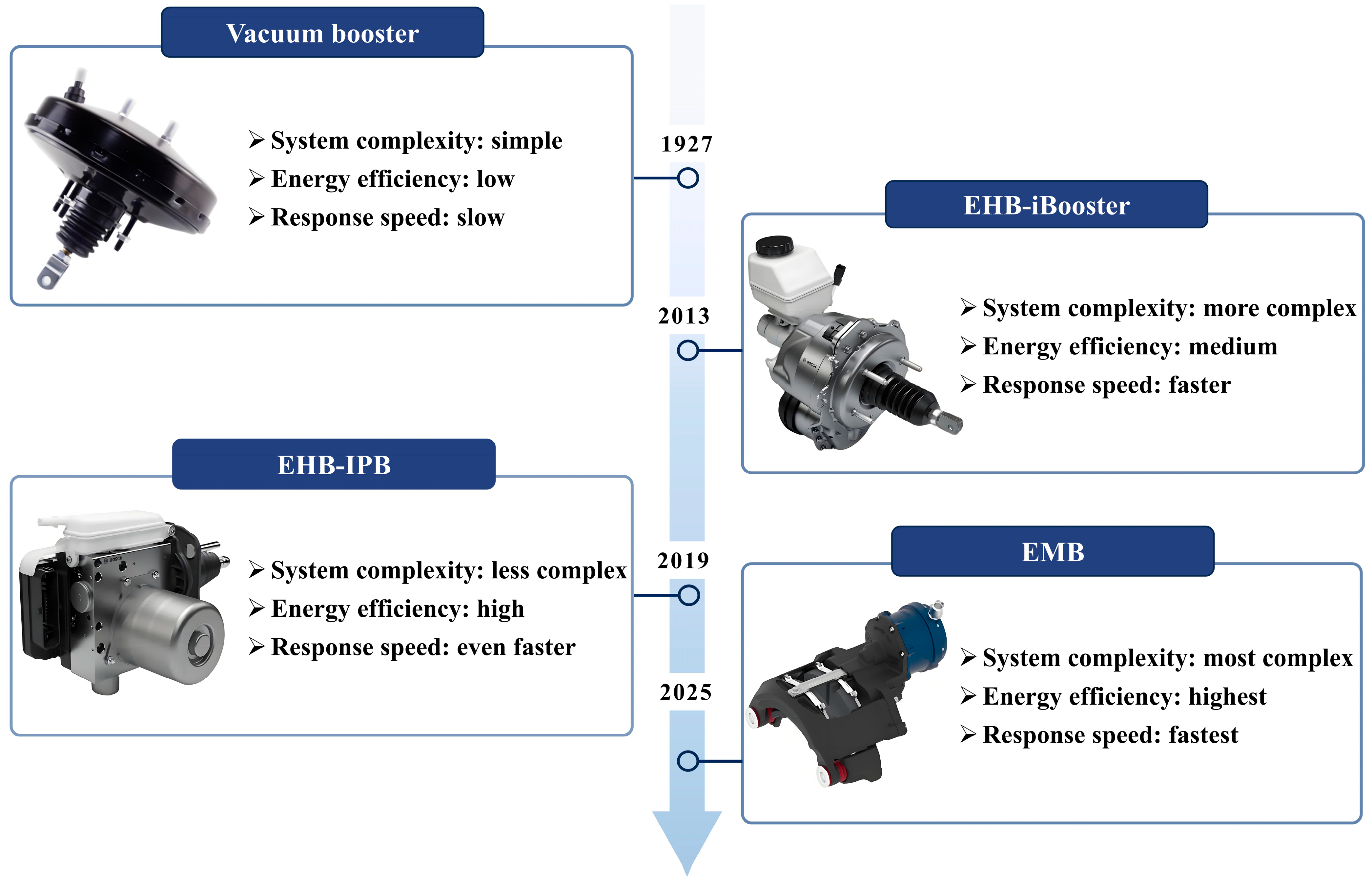
2. A Classification and Structural Analysis of the BBW System

As a key core technology for new energy vehicles, the BBW system can be classified into the electro-hydraulic braking (EHB) system, the electro-mechanical braking (EMB) system, and the hybrid braking system (such as pneumatic braking, electromagnetic braking, etc.), based on differences in system structures and working principles. Figure 1 illustrates the development history of the BBW system, showing the technological evolution from traditional braking to the BBW system. Given that current research mainly focuses on the EHB and EMB systems, which are the most representative, this section will focus on explaining the basic architecture, working principles, and representative products of these two types of systems. It is worth noting that Ref. [22] classifies the regenerative braking system (RBS) as a type of BBW system. However, from a technical standpoint, regenerative braking should be categorized under electric motor braking, and this technology has been widely applied in the EHB and EMB systems. Since regenerative braking is crucial in improving the driving range of pure electric vehicles, this section will discuss it separately, focusing on its working principles and operating conditions.

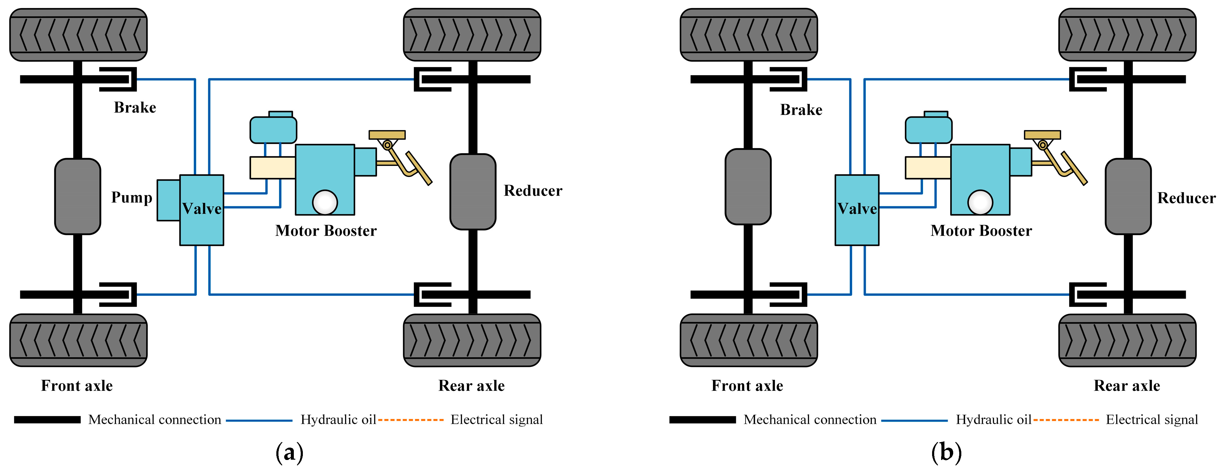
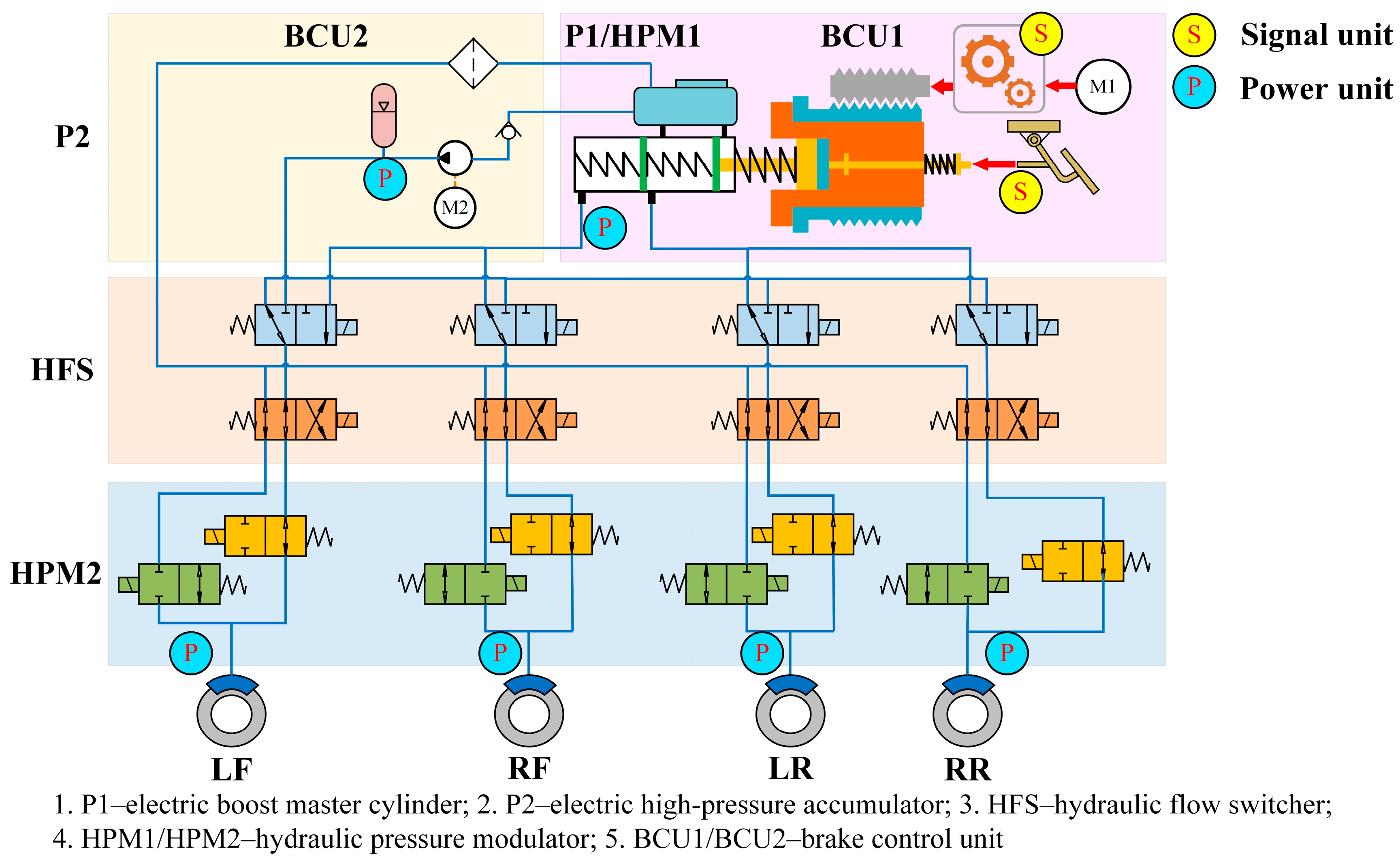
2.1. Electro-Hydraulic Braking System

The EHB system consists of a pedal input unit, an electronic control unit (ECU), a hydraulic control unit (HCU), and brake actuators. When the driver presses the brake pedal, the pedal input unit detects the pedal stroke and force in real-time through sensors, converts the physical signals into electrical signals, and transmits them to the ECU. The ECU interprets the driver’s braking demand based on these signals and dynamically adjusts the braking pressure of the wheels through the HCU by combining the current driving status (such as vehicle speed and load) and road surface information to achieve precise braking control. Based on the traditional hydraulic braking system, the EHB system retains key components such as hydraulic pipelines and valves. It offers an excellent braking performance at a relatively low cost and adopts a redundancy design to further enhance system safety. The most significant difference between the EHB and the traditional hydraulic braking system lies in the design of the brake booster: the traditional vacuum booster is replaced by a pump-driven accumulator or a motor-driven booster. Accordingly, EHB systems are classified into pump-driven accumulator EHB and motor-driven booster EHB [23]. This design improves the control accuracy while significantly enhancing energy efficiency. The following sections will study the structural features and representative products of these two types of EHB systems.
The structure of the pump-driven accumulator EHB system is shown in Figure 2. The system pressurizes the accumulator using a hydraulic pump and regulates the operation of a switching solenoid valve to achieve the precise control of the braking pressure. Representative applications include the electronically controlled brake (ECB) system equipped on the Toyota Prius [24], the sensotronic brake control (SBC) system used in Mercedes-Benz GLS, SL, and E-Class models [25], the slip control boost (SCB) system developed by TRW (Livonia, MI, USA) [26], and the Mando electro-hydraulic brake (MEB) system launched by Mando (Seongnam, Republic of Korea). However, the inherent intermittent operation of the hydraulic pump can lead to pressure fluctuations, which in turn affect the accuracy of the pressure tracking. Moreover, the relatively slow pressure buildup of the pump and potential pressure leakage in the accumulator reduces the braking efficiency and increases energy consumption.
To address the above-mentioned issues, motor-driven booster EHB can be adopted, which utilizes the strong servo characteristics of the motor to quickly build up braking pressure and achieve precise control while significantly reducing energy consumption. Depending on the integration level of the ECU and HCU, the motor-driven booster EHB system can be divided into Two-Box and One-Box configurations, as shown in Figure 3. In the Two-Box configuration, typical representative products include Bosch’s iBooster [27], Hitachi’s e-ACT [28], and the eBooster from Shanghai Huizhong Automotive Manufacturing Co., Ltd. (Shanghai, China). The Two-Box system adopts a semi-decoupled brake design, where the servo motor drives the master cylinder to provide braking assistance, and the braking pressure is distributed to the four brake wheel cylinders, achieving vehicle deceleration. However, in this configuration, the ECU and HCU are designed separately, requiring integration with the electronic stability control (ESC) system to meet the braking redundancy requirements for autonomous driving in new energy vehicles. As a result, the Two-Box configuration faces drawbacks such as lower integration, difficulties in ECU-HCU coordination, and inefficient space utilization. In contrast, the One-Box configuration features a highly integrated design for the electro-hydraulic braking system, combining the ECU, HCU, motor, master cylinder, and pedal feel simulator into a single unit. It also integrates core functional modules such as the ESC, while optimizing the hydraulic circuit design and removing redundant components like the plunger pump. In addition, the One-Box solution further enhances braking safety by combining it with mechanical redundancy (e.g., sub-master cylinder) or electronic redundancy (e.g., dual-loop electronic control) to form a dual redundancy mechanism. Typical products include Bosch’s IPB system [29], Continental’s MKC1 system [30], and ZF’s integrated brake control (IBC) system. Therefore, as shown in Table 1, compared to the Two-Box configuration, the One-Box configuration shows significant advantages in terms of space and cost savings, an improved response speed, simplified control logic, and optimized functional coordination. It is better aligned with the development needs of new energy vehicles and has become the direction for future development in the field of electro-hydraulic braking systems.
Despite some limitations of the electro-hydraulic braking system, such as the high maintenance costs, system response delays, strong dependence on hydraulic lines and seals, and the need for improved energy recovery efficiency, the technology is highly mature and has been long validated in the market. It is now widely used in new energy vehicles.

2.2. Electro-Mechanical Braking System

Unlike the electro-hydraulic braking system, the electro-mechanical braking system is a purely electronic braking technology, which completely abandons the hydraulic components in the traditional braking system (such as hydraulic lines, brake fluid, hydraulic pumps, etc.), and relies on the real-time detection of the pedal sensor signals by the ECU and uses the electric motor to directly drive the brake actuator directly, realizing highly efficient and precise braking control. With notable advantages, such as its simplified structure, fast response, and high control accuracy, EMB is a key development direction for future braking technologies in new energy vehicles. However, this technology still faces several challenges:
(1)
The system lacks a redundancy design, resulting in reduced safety.
(2)
Due to spatial constraints, the motors used are relatively small, making it difficult to generate sufficient braking force.
(3)
The motors operate under complex conditions, requiring additional costs to improve reliability, such as an enhanced heat resistance and electromagnetic interference protection.
As the technology is not yet fully mature and the cost is high, the commercial application of related products still faces major challenges, and most of them are still in the research and development stage, as shown in Figure 4.

2.3. Regenerative Braking System

Regenerative braking is essentially an energy recovery technology based on the motor. Its working principle is illustrated in Figure 5. During vehicle deceleration or braking, the motor switches to the generator mode, converting a portion of the vehicle’s kinetic energy into electrical energy via the inverter and storing it in the power battery, while the remaining energy is dissipated as heat through traditional friction braking. As a representative of new energy vehicles, electric vehicles have long been constrained by the critical limitation of their driving range. Regenerative braking technology can significantly increase the vehicle range by 25–40% by efficiently recovering the kinetic energy in the braking process and realizing energy reuse [20], which effectively breaks through a major technological barrier in the development of NEVs.
The maximum braking torque output of the regenerative braking system is jointly constrained by the motor’s operating characteristics and the battery’s state. Specifically, the upper limit of the regenerative braking torque is determined by the motor’s peak torque and the battery’s allowable charging power. Furthermore, when the battery’s state of charge (SOC) exceeds its safe operating range (SOC < 10% or SOC > 90%) [21], the regenerative braking function is automatically disabled, and the system reverts to traditional friction braking to ensure braking safety and performance.

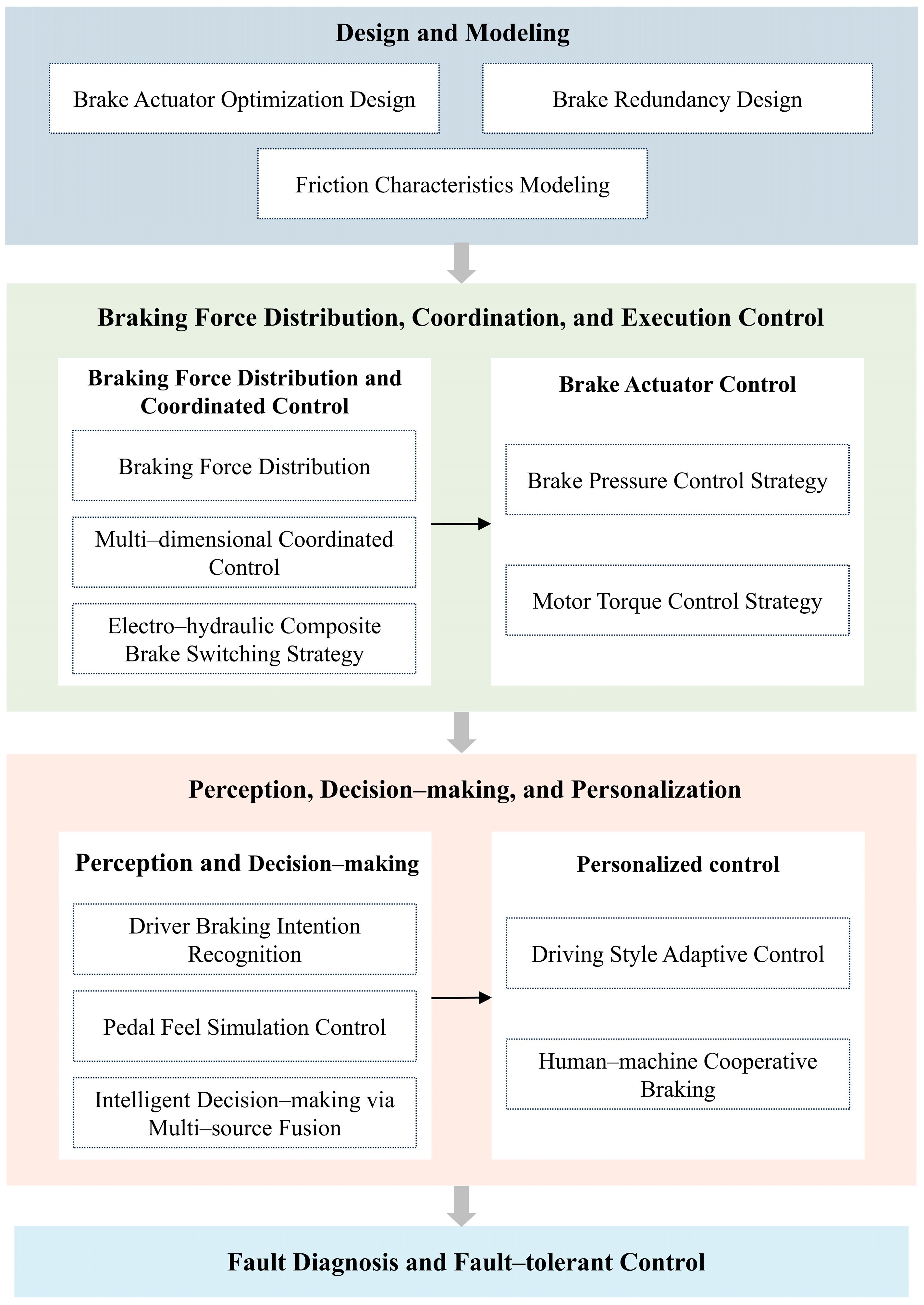
3. Key Technologies of the BBW System

As an innovative intelligent braking system, the BBW system relies heavily on its key technologies to improve system performance. As illustrated in Figure 6, these technologies can be categorized into several core areas. First, system design and modeling, braking force distribution and coordination control, and brake actuator control are the basic technologies to ensure the efficient operation of the BBW system, which involves the precise control and coordination of the system. Second, system perception decision-making and personalized control aim to enhance the system’s intelligence, adaptability, and flexibility. In addition, fault diagnosis and fault-tolerant control technologies are crucial for improving the safety and reliability of the BBW system. Through in-depth research and optimization in these areas, the BBW system has achieved significant advancements in response speed, control accuracy, and system safety, laying a solid technical foundation for the performance and safety assurance of new energy vehicles.

3.1. The Design and Modeling of the BBW System

The structural optimization design and modeling of the BBW system are core elements in achieving high-performance and reliable braking control. For example, the optimized design of brake actuators can reduce structural complexity and enhance the braking force output. A brake redundancy design improves the safety of new energy vehicles by ensuring reliable braking through backup mechanisms in case of a system failure. Additionally, friction characteristics, such as those of the actuator and the transmission system, can affect the precision of braking control [31,32,33,34]. Therefore, this section will discuss the optimization of brake actuators, brake redundancy design, and friction characteristic analysis in detail.

3.1.1. Optimal Design of the Brake Actuator

Brake actuators are a crucial component of the BBW system, as their performance directly affects the response speed, accuracy, and stability of the braking force. In recent years, researchers have proposed various optimized design schemes around different types of the BBW system. In the field of EMB, Zhang Z et al. [35] designed a novel force augmentation mechanism containing bidirectional eccentric wheels based on the synchronous force augmentation disk EMB (SFD-EMB) scheme, as shown in Figure 7a. They thoroughly investigated the relationships among the augmentation ratio, the thrust displacement, and the dimensional parameters and employed a particle swarm algorithm to optimize the key parameters, thereby reducing the braking response time by 68.8%. In addition, Xiao F et al. [36] proposed an EMB actuator that combines a linear motor with a lever mechanism, eliminating the need for traditional motion conversion components. The permanent magnet array in the linear motor is arranged in a Halbach configuration to enhance the thrust, and the lever mechanism further amplifies the braking force, ensuring sufficient braking output. Compared with conventional EMB, EWB, and direct-drive brake (DDB) systems, this scheme offers significant advantages in structural simplification and feasibility. For the EHB system, refs. [37,38] proposed to adopt a cam mechanism as a clamping actuator, where cam profiles are optimized via algorithmic methods to enhance the motor braking torque, thereby improving the braking efficiency and system stability. As shown in Figure 7b, in the EWB system, the traditional wedge mechanism utilizes self-reinforcing mechanical characteristics to amplify the braking force. However, the system is more sensitive to parameter errors. To address this issue, Park H et al. [39] developed an electronic non-circular gear brake that reduces the sensitivity to parameter errors and validated the feasibility of the design through experimental testing. Moreover, Ahmad F et al. [40] proposed a novel EWB design based on an electronic fixed caliper, employing a ball screw drive shaft to convert the motor’s rotational motion into linear displacement, which drives a sliding beam to activate the wedge mechanism and achieve accurate braking force transmission. Compared with traditional EWB actuators, this design exhibits a superior structural compactness and control precision.

3.1.2. Brake Redundancy Design

The development of new energy vehicles is closely tied to advancements in vehicle intelligence, with autonomous driving technology emerging as an inevitable trend in the industry. The traditional single-path braking scheme can no longer meet the safety requirements of high-level autonomous driving. In contrast, redundancy designs significantly improve the reliability and safety of the BBW system by constructing multiple sets of independent braking circuits, which can still maintain the basic braking function when the main braking circuit fails.
In the field of redundancy design, beyond the basic schemes such as dual motors and dual ECUs, researchers have carried out various innovative research projects. Based on a novel dual-redundant electro-hydraulic brake (DREHB), Li C. et al. [41] introduced a three-stage cascaded modular decoupling architecture, as shown in Figure 8. This architecture consists of a hydraulic power unit, hydraulic flow switching valves, and hydraulic pressure regulators. Through the matching and optimization design of key parameters, combined with the system simulation and hardware-in-the-loop (HIL) experiments, it is verified that the scheme meets the higher performance requirements in braking safety and system efficiency. Yuan C. et al. [42] developed a dual-source redundant braking (DSRB) system that replaces conventional inlet and outlet valves with a combination of hydraulic pumps, throttle valves, and balancing valves. The results show that this system can still maintain an effective braking performance and pressure control accuracy even under extreme conditions where the inlet and outlet valves and hydraulic motors partially or even completely fail, which meets redundancy requirements for intelligent vehicle braking systems. Researchers have also made significant progress in the redundant design of electronic control systems. To address power supply failures, Liu Q. [43] proposed a heterogeneous power supply backup scheme that utilizes a DCDC inverter to boost the voltage from the low-voltage battery and cooperatively supply power with a supercapacitor when the primary circuit fails, ensuring the stable and continuous operation of the BBW system. In addition, Lee KJ et al. [44] proposed an asymmetric dual-core ECU redundancy architecture for the EMB system, which adds an external watchdog processor hardware structure to the primary and auxiliary processing units to ensure a reliable braking performance even in the event of dual hardware and software failures. In addition to the redundancy design of actuators and control units, the redundant configuration of sensors, as key information acquisition components, is also an important direction to enhance the overall system reliability. To address the issue of emergency shutdowns in motor systems caused by phase current sensor failures, Ref. [45] proposed a survivable operation technique for three-phase induction motor (IM) drive systems. When the current sensor fails, the original vector control strategy is seamlessly switched to a simplified mathematical control method to ensure a continuous and stable system operation. On the other hand, Ref. [46] pointed out that redundant sensors do not need to achieve the high accuracy requirements of primary sensors. Based on this insight, the authors innovatively proposed a cyber-approximate sensor design from the network perspective, utilizing existing computational resources and regression models to approximate sensor functionality, effectively reducing physical redundancy costs by about 50% and improving performance by approximately 7%.

3.1.3. Friction Characteristics Modeling

Most research on the BBW system is based on ideal conditions, with less consideration of the impact of the internal friction within the system. As a result, the designed control strategies are limited to ideal operating conditions, leading to inevitable errors in practical applications. Therefore, accurately establishing a friction characteristics model for the BBW system is key to improving the precision of control strategies. However, traditional friction models, such as the Coulomb friction model [47,48], the Stribeck friction model [49,50], and the LuGre friction model [51,52], have notable shortcomings in characterizing the strong transient and nonlinear dynamic characteristics of the BBW system. Therefore, researchers have proposed various improvements. Ref. [23] proposed a load-dependent continuous asymmetric friction characteristics model, while other models include the three-stage friction model [53], exponential decay friction model [54], and pressure-based continuous friction model [55]. These improved friction models aim to more accurately describe the dynamic characteristics of the BBW system, thereby achieving the precise tracking of the target braking pressure.

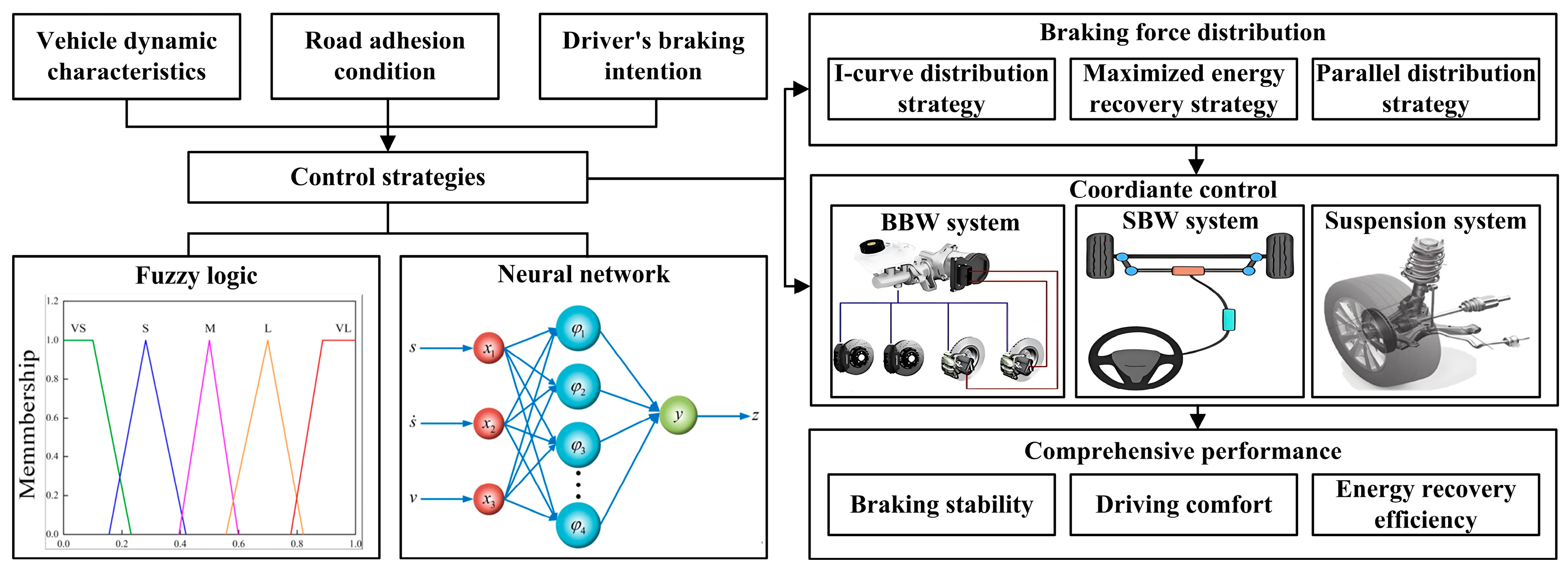
3.2. The Braking Force Distribution and the Coordinated Control of the BBW System

The braking force distribution and coordination control is one of the core technologies of the BBW system, directly influencing the energy recovery efficiency, braking stability, and driving comfort of new energy vehicles. Since the BBW system adopts an electronic control execution, the effectiveness of its braking force distribution and coordination control highly depends on the design and implementation of the control strategy, and the quality of the control strategy directly determines the braking system’s performance. In addition, as shown in Figure 9, the control strategy needs to comprehensively consider factors such as vehicle dynamic characteristics, road adhesion conditions, and driver braking intentions but also needs to coordinate with other chassis control systems, such as the suspension and steering systems, which imposes higher requirements on the precision, robustness, and real-time performance of the control strategy. Therefore, in-depth research into the braking force distribution and coordination control mechanisms of the BBW system plays a key role in enhancing vehicle safety, comfort, and energy efficiency.

3.2.1. Braking Force Distribution

Pure electric vehicles, as key carriers for the BBW system, must not only guarantee fundamental braking safety, such as direct yaw moment control [56,57,58] and anti-rollover control [59], but also need to enhance the driving range. Regenerative braking technology plays a crucial role in achieving this goal. Its core lies in the rational distribution of the braking torque, whereby the electric motor operates in generator mode to recover braking energy and store it in the battery for future use. Typical braking force distribution strategies are summarized in Table 2. On this basis, researchers have conducted more in-depth research. Table 3 illustrates the energy recovery efficiency comparison of various advanced braking force distribution strategies. Meanwhile, Tang M et al. [60] proposed an optimal regenerative braking control strategy based on the road conditions, vehicle load, and driver braking intention. This approach identifies and estimates the braking intention and load using modal characteristics and a genetic factor recursive least squares algorithm and applies the artificial bee colony algorithm to optimize the front and rear braking force allocation, significantly improving the energy recovery efficiency while shortening the braking distance.
Sun H et al. [61] developed an online braking torque allocation (LBTA) strategy that comprehensively accounts for motor, hydraulic, and tire losses. By prioritizing the motor braking force, the braking force distribution problem is formulated as a linear programming model and solved using a cubic polynomial approach. Compared with the fixed proportional distribution strategy, this strategy improves the energy recovery efficiency by 1.5% and 4.3% under normal and high-speed driving cycles, respectively. Hosseini Salari et al. [62], focusing on in-wheel motor electric vehicles, proposed a novel method to enhance the regenerative braking efficiency by leveraging the compensatory capability of the electronic brakeforce distribution (EBD). The experimental results showed that the proposed control strategy significantly increased the battery energy recovery, extending the driving range by 24%. To further improve the driving range and battery lifespan in electric vehicles, Wu J et al. [63] proposed a regenerative braking control strategy based on Munchausen Prior Expert–Soft Actor–Critic (MPE-SAC), with the optimization of the regenerative braking energy recovery efficiency and battery life as the comprehensive objectives. Simulation and hardware-in-the-loop (HIL) testing demonstrated that the MPE-SAC strategy outperforms DDPG, TD3, and SAC algorithms in both regenerative efficiency and battery longevity, achieving 99.28% of the performance of the dynamic programming (DP) algorithm. It is worth noting that although the dynamic programming algorithm has a strict mathematical convergence proof and can guarantee to find the optimal solution, due to its poor adaptive ability and high computational resource demand, in practical applications, researchers usually choose to sacrifice part of the accuracy to adopt other optimization algorithms. Therefore, the optimal solution of the DP algorithm is generally used as a benchmark to evaluate the performance of optimization algorithms.
Table 2. Typical braking force distribution strategies.
Braking Force Distribution StrategyCharacteristic CurveDistribution Principle
I-curve distribution strategyEnergies 18 02702 i001If z ≤ 0.15, in the AB segment, the braking force is provided by the front axle; otherwise, in the BE segment, the braking force is distributed according to the I-line.
Maximized energy recovery strategyEnergies 18 02702 i002
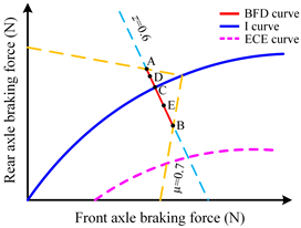
If the motor’s maximum braking force is less than the front axle’s, braking force is distributed at point C; if greater, at point E; otherwise, at point B.
Parallel distribution strategyEnergies 18 02702 i003If z < 0.1, braking force is provided by the front axle and distributed in the AB segment; if 0.1 ≤ z < 0.5, in BC; if 0.5 ≤ z < 0.7, in CD; if z ≥ 0.7, in DE.
Table 3. Energy recovery efficiency comparison of advanced braking force distribution strategies.
Control StrategiesEnergy Recovery EfficiencyReference
Multi-energy recovery modeEnergy recovery efficiency improved by 15.8% compared to the baseline mode[64]
Double layers multi-parametersThere is a 16.91% increase in energy recovery efficiency over the parallel RB strategy[65]
Swarm intelligence-based MPC strategyCompared to the rule-based strategy, energy recovery efficiency increased by 17%[66]
In addition, to address the conflict between energy recovery and braking safety in regenerative braking systems, two main control strategies are adopted: one is to use the regenerative braking system under regular braking conditions and stop using it under emergency braking conditions; the other is to utilize the rapid response capability of the motor to apply braking force preferentially under regular and emergency braking conditions to make up for the delayed response of the hydraulic braking system and to work together with the motor to ensure braking safety while realizing braking energy recovery after the intervention of the hydraulic braking system. The first strategy is simple and reliable, and most BBW systems still use this method. However, due to the inherent delay in hydraulic braking, when the regenerative braking is disengaged, the hydraulic system often fails to provide sufficient braking force in time, resulting in a sudden drop in the total braking force, causing a braking impact and leaving the energy from emergency braking unrecovered. Therefore, researchers have begun exploring the second strategy. For example, Ref. [5] used model predictive control (MPC) to combine a regenerative braking system (RBS) with an anti-lock braking system (ABS) and prioritized regenerative braking to achieve braking control and energy recovery by calculating the target braking torque at the optimal slip rate. In [67], a control strategy is proposed to coordinate the RBS and ABS based on logical threshold control and phase-plane theory, effectively improving the energy recovery efficiency and braking performance compared to traditional methods.
Meanwhile, with the increasing range of electric vehicles, consumers’ requirements for driving comfort have increased. In longitudinal motion control, driver discomfort primarily arises from fluctuations in jerk (the rate of change in acceleration), which becomes particularly obvious during braking. Therefore, Ref. [68] takes regenerative braking efficiency and jerk as control objectives and applies advanced optimization algorithms to achieve the comprehensive optimization of the braking energy recovery efficiency and ride comfort. Furthermore, Ref. [69] develops a personalized MPC strategy based on driving behavior data under typical car-following conditions using the characteristic E method. This strategy not only achieves a consistent braking feel across different driving styles but also improves the response amplitude by 5.6%, significantly enhancing braking smoothness. These findings provide important theoretical and technical support for improving the ride comfort of electric vehicles.

3.2.2. Multi-Dimensional Coordinated Control

The increase in the complexity of control objects and the growth of consumer demand make it difficult for single-dimensional control strategies to meet actual needs. Multi-dimensional coordinated control can significantly optimize vehicle dynamics and comprehensively enhance safety, comfort, and energy efficiency by integrating control strategies in multiple dimensions, such as longitudinal, lateral, and vertical. Taking longitudinal braking as an example, the suspension system, as a key subsystem for enhancing ride comfort [70,71,72], and its coordinated control with the braking system not only helps to realize braking energy recovery but also effectively suppresses the pitch (nodding) motion during braking. For example, Ref. [73] integrated the braking system with the suspension system to design a robust regenerative braking comfort control strategy. This strategy maintains an effective control performance under uncertain external disturbances, such as square and sawtooth waves, significantly enhancing ride comfort while improving braking safety. In [74], based on the coupling effects between longitudinal and vertical dynamics, a comprehensive control framework combining neuro-fuzzy control and model predictive control was proposed, achieving the synchronization between energy recovery efficiency and ride comfort optimization. Regarding longitudinal–lateral control, the focus lies on the vehicle dynamic motion control. Under complex driving scenarios, such as emergency avoidance or low-adhesion surfaces, coordinating braking and steering actions can effectively prevent vehicle skidding or oversteering [75]. For electric vehicles, longitudinal–lateral control strategies integrated with regenerative braking can further improve the energy recovery efficiency [76]. The longitudinal–lateral–vertical coordinated control is a deeper fusion of the above two, enabling a multi-dimensional optimization that comprehensively enhances the overall vehicle performance [77].

3.2.3. Switching Strategy for Electro-Hydraulic Composite Braking

At present, pure electric vehicles and hybrid electric vehicles (HEVs) widely adopt electro-hydraulic composite braking systems, which not only ensure braking performance but also enable efficient energy recovery. In practical operations, the system dynamically switches between three modes: electric braking, hydraulic braking, and composite braking. When the motor braking torque is insufficient to meet the driver’s braking demand, the system automatically shifts to a composite or pure hydraulic braking mode. However, braking mode switching processes may lead to abrupt changes in braking torque, resulting in a braking impact that significantly compromises ride comfort. Therefore, a well-designed switching strategy is required to achieve smooth transitions between different braking modes and enhance braking comfort.
In the research on electro-hydraulic composite braking systems for pure electric vehicles, Zhang L et al. [78] proposed an innovative smoothness-oriented control strategy based on a hierarchical architecture. By introducing a motor torque compensation module, the strategy effectively mitigates impacts during braking mode transitions and significantly improves braking comfort. On this basis, Zhang R et al. [79] further considered the influence of the vehicle load and road surface friction coefficient, proposing a novel μ-H∞ switching control strategy that precisely determined the state transition conditions for braking modes and employed a regenerative torque compensation mechanism to reduce the deviation between the actual and desired braking torque through the regenerative braking torque compensation mechanism, which reduces the braking torque fluctuation by 78.3% and significantly improves the ride comfort during mode switching. For electric vehicles equipped with a two-speed automatic transmission, Liu Y et al. [80] developed an adaptive braking mode switching strategy, as illustrated in Figure 10. The method takes into account the dynamic characteristics of regenerative torque during release and storage phases and utilizes a multi-objective cuckoo search algorithm to optimize the shifting strategy. Simulation and experimental results demonstrate the method’s effectiveness in improving the shift smoothness and braking comfort. In the field of HEVs, Jo C et al. [81] proposed a cooperative regenerative braking control strategy for the downshifting process of a six-speed automatic transmission with regenerative braking, aiming at balancing the braking demand and improving driving comfort. The strategy fully considered the response characteristics of the electric motor and the hydraulic braking system and successfully reduced the deceleration amplitude by 88% through the motor torque compensation control, significantly enhancing braking smoothness. In addition, Yang Y et al. [82] analyzed the clutch and hydraulic system characteristics in-depth and proposed a two-stage switching control strategy. In the first stage, the smooth transition of the braking mode is realized by adjusting the clutch engagement torque and the motor force change rate in real-time. In the second stage, the strategy combines the dynamic adjustment of the target braking torque with the active coordination of the motor to ensure stable and continuous braking torque. The results indicate that the proposed strategy can effectively reduce torque fluctuations during the braking–switching process and improve the overall driving comfort.

3.3. The Control of Brake Actuators in the BBW System

Whether it is active braking technologies, such as electronic stability control (ESC) and autonomous emergency braking (AEB), or the driver’s manual braking operations, all rely on a fast and precise braking system, the essence of which ultimately lies in the control of the actuators. For the electro-hydraulic braking system, the actuators consist of the motor braking system and the hydraulic braking system. While in the electro-mechanical braking system, the actuators are composed solely of the electric braking system. The following sections will discuss the control strategies for these two types of actuators, respectively.

3.3.1. Brake Pressure Control Strategies

The implementation platform for the brake pressure control strategy is the EHB system. Traditional EHB pressure control strategies mainly include PID control [83,84,85], improved PID control [86,87,88,89], sliding mode control [90,91,92,93], and MPC [94,95]. However, these methods are difficult to balance between “rapid active pressure building” and “precise pressure control”. Therefore, Shan T et al. [96] employed a decoupled pressure observation method to eliminate errors caused by mechanical–fluid coupling. They further optimized the control of electromagnetic switching valves using a Q-learning algorithm, ensuring a fast response and precise pressure control. Zhao Y et al. [97], based on the measurements and calibration from a dynamic parameter test rig, developed an accurate mathematical model of the braking system. Considering the system’s time-varying parameters, they proposed a logic-threshold brake pressure control strategy combining analog model predictive control (AMPC) and feedback control. Experimental results showed that the proposed method could accurately control the pressure with an error of less than 0.08 bar and improved the response speed by 32.5% compared to conventional control algorithms. In addition, Zhu B et al. [98] proposed a wheel cylinder pressure control strategy based on motor solenoid valve collaborative fluid replenishment logic to address the issue of sudden stiffness changes in hydraulic systems. This strategy consists of a feedforward pressure loop based on the variable stiffness fitting of the hydraulic system, a robust sliding mode position loop, and a motor current loop. It can dynamically adjust the built-in parameters of the pressure controller according to changes in stiffness characteristics, achieve precise pressure control, and quickly respond to the demand for brake fluid replenishment in a short period. On the other hand, Ma C et al. [99] developed a multi-channel time-sharing pressure control strategy that achieves a simultaneous or partially simultaneous pressure control. Compared to the IBC system, this strategy significantly improves the control time and response accuracy.

3.3.2. Motor Torque Control Strategies

The permanent magnet synchronous motor (PMSM) driven by a three-phase sinusoidal current is the most widely used traction motor in new energy vehicles. At present, the mainstream control methods mainly include direct torque control (DTC) [100] and field-oriented control (FOC) [101]. DTC directly regulates the motor flux and torque, enabling fast and efficient control. It continuously monitors flux and torque states and employs a hysteresis controller and a switching table to select the optimal voltage vector, thereby simplifying the control process. In contrast, FOC is based on decoupling principles. Its core lies in decomposing the stator current vector into direct-axis (Id) and quadrature-axis (Iq) components, enabling precise torque regulation by independently adjusting these orthogonal components. In addition, in recent years, advanced strategies such as hybrid DTC–FOC [102], finite-set model predictive control (FS-MPC) [103], and non-singular terminal sliding mode-based direct torque control (NSTSM-DTC) [104] have further improved the control performance of PMSMs.

3.4. Perception and Decision-Making in the BBW System

The perception and decision-making module of the BBW system is crucial in the efficient and safe braking of new energy vehicles. The perception layer collects driver input and vehicle status information through multiple sensors, such as pedal displacement sensors and wheel speed sensors. Based on this information, the decision-making layer formulates optimal control strategies and commands to drive the actuators accordingly. This section focuses on driver braking intention recognition, pedal sensation simulation control, and intelligent decision-making methods based on multi-source information fusion.

3.4.1. Driver Braking Intention Recognition

Driver braking intention recognition is a key link in the perception and decision-making process. By analyzing signals such as the brake pedal displacement, pedal speed, and vehicle speed, it accurately determines the driver’s braking demand and provides a basis for the subsequent braking force distribution. The traditional braking intention recognition method mainly relies on rule-based control strategies. For example, Ref. [105] proposed an approach that considers the pedal displacement, pedal speed, and vehicle velocity, while incorporating the pedal pressing force and steering wheel angle to enhance the recognition accuracy. Ref. [87] utilized fuzzy inference based on the master cylinder pressure and its variation rate to identify braking intentions. However, fuzzy inference remains inherently rule-driven, and its recognition accuracy is limited by the rationality of the rules. The formulation of rules usually requires a lot of debugging and optimization [106,107]. To overcome the above limitations, researchers have gradually introduced advanced algorithms, such as machine learning [108,109,110], to improve the intelligence and accuracy of brake intention recognition. Li X et al. [111] proposed a recognition method based on an artificial bee colony optimization support vector machine (ABC-SVM), which utilizes neighborhood components analysis (NCA) to extract effective features and combines the ABC-SVM algorithm for intention recognition. The results show that compared with algorithms such as fuzzy inference, the backpropagation (BP) neural network, and the particle swarm optimization support vector machine (PSO-SVM), this method can more quickly and accurately identify the driver’s braking intention. Zheng H et al. [112] developed a dual-model framework combining neural networks and fuzzy inference to handle normal and emergency braking scenarios, validating its effectiveness in complex traffic environments. Yang W et al. [113] introduced a driver intention recognition model for leading vehicles in rear-end AEB systems, integrating BP neural networks and hidden Markov models (HMMs). The model successfully recognized constant-speed driving, normal braking, and emergency braking conditions with an accuracy of up to 98%, outperforming single BP or hidden Markov models. Wang S et al. [114] further designed a hybrid model that combines a long short-term memory (LSTM) neural network with a Gaussian hidden Markov model (GHMM). They applied the SVM–recursive feature elimination (SVM-RFE) to select key features and used random search to optimize LSTM hyperparameters. Compared to the GHMM alone, the proposed method significantly improved the recognition accuracy. In addition, some researchers have extended the scope of braking intention recognition from traditional physical operation signals to the driver’s physiological state, proposing more intelligent and forward-looking approaches. Compared to methods based solely on pedal input, these techniques leverage data such as body posture [115], eye movement [116], electroencephalogram (EEG) signals [117], or a combination of eye and EEG data [118] to enable more a direct and precise recognition of driver intentions.

3.4.2. Pedal Feel Emulation Control

The future development trend of the brake-by-wire system is to achieve full electrification. In the Two-Box configuration, the brake pedal is not yet fully decoupled and remains mechanically or hydraulically connected to the braking system. In contrast, the One-Box configuration achieves complete decoupling by using sensors to capture the mechanical signal of the driver pressing the brake pedal and converting it into an electronic signal for transmission to the control system and actuators. Meanwhile, pedal feel emulation control utilizes simulators to replicate the feedback of traditional hydraulic brake systems, ensuring a natural and intuitive operating experience for the driver. Regarding structural design, Qu X et al. [119] developed a hybrid disk–drum magnetorheological (MR) pedal force modulation device. Its reliability was validated through finite element optimization and prototype testing, demonstrating a wide output torque range of 0.2–32 N·m, which facilitates precise pedal force control. U. Caliskan et al. [120] proposed a force–feedback-based series elastic pedal feel emulation control method. By integrating a flexible element between the brake pedal and the actuator and introducing a robust controller, the method effectively compensates for the pedal feel while overcoming external disturbances such as friction, stiction, and slip. The results show that this approach significantly improves the braking safety and driving comfort while reducing the frequency of hard braking. Wang D et al. [121] developed an adjustable brake pedal simulator employing a disk-type magnetorheological damper as the emulator. A real-time zero-regression current tracking algorithm (RTZRC) was used to address the simulation lag, improving the repeatability of the pedal force and the tracking accuracy of the pedal characteristic curve. In addition, considering potential faults in the pedal feel simulator, Ref. [97] proposed a redundant control method combining a pedal feel simulation motor and a simulation valve. When the motor fails, the simulation valve adjusts the pressure in the front chamber of the master cylinder to compensate for the pedal feel and maintain consistent pedal characteristics.

3.4.3. Intelligent Decision-Making Based on Multi-Source Information Fusion

In the context of brake-by-wire (BBW) systems, intelligent decision-making based on multi-source information fusion integrates the vehicle state data, driver braking intention, and environmental perception information to analyze road conditions in real-time and make optimal decisions [122,123,124], thereby achieving the active safety and energy efficiency optimization of new energy vehicles. For instance, Yang W et al. [125] proposed an active anti-collision warning model that considers the driving intention of the preceding vehicle. This model utilizes a BP neural network and a hidden Markov model to construct a braking intention recognition framework based on observation data, such as the brake pedal position, accelerator pedal status, and vehicle speed. It further fuses vehicle-to-vehicle (V2V) communication data and road adhesion information to inform the following vehicle, enabling real-time warning adjustment and braking execution control. The simulation and experimental results validated the effectiveness of this strategy in avoiding collisions during automatic emergency braking scenarios, achieving an average intention recognition accuracy of 94.17% and a positive alarm rate of 93.43%. Zhu B et al. [126] developed a braking force distribution strategy based on multi-source information fusion and comprehensively considered the constraints of the battery, motor, and braking system. Furthermore, they proposed a vehicle-to-infrastructure (V2I) optimal control strategy under MPC with soft constraints based on the rolling optimization theory. Research showed that both strategies, when integrated with traffic information, enabled optimal decision-making and significantly improved the vehicle economy and driving comfort. Shang Y et al. [127] presented an adaptive regenerative braking energy recovery strategy, based on the multi-source fusion of the traffic sign recognition, GPS, road slope, and vehicle operating parameters. This strategy enables the motor to operate near its optimal efficiency point under different braking conditions. Compared to traditional series control and fuzzy control strategies, the energy recovery efficiency was improved by 11.9% and 5.3%, respectively.

3.5. The Personalized Control of the BBW System

Currently, the research on BBW systems mainly focuses on the system itself, such as the rational allocation of braking force and the precise control of actuators. However, there has been relatively little research on individual driver factors, such as driving style. The survey data show that about 90% of traffic accidents are related to human factors [128]. In actual braking scenarios, driver behavior often exhibits inconsistencies due to individual differences. Therefore, integrating the driver’s driving style into the BBW system’s control strategy can enhance the safety and comfort of braking, further enriching the driving experience. This section will review the related research on driving style adaptive control and human–machine collaborative braking control.

3.5.1. Driving Style Adaptive Control

Research on driving style adaptive control aims to identify and model drivers’ personalized characteristics to achieve an intelligent coordination between control systems and human driving behaviors, thereby improving the driving comfort and energy efficiency while ensuring driving safety. In the context of the BBW system, Ref. [69] breaks away from the traditional vehicle-performance-centered control concept by introducing a personalized MPC strategy that integrates a driving behavior characteristic index E. This strategy collects and analyzes driver behavior data in real-time to construct an adaptive control algorithm, effectively accommodating diverse driving patterns while significantly improving the braking safety and ride comfort. Similarly, Ref. [129] identifies key parameters that characterize driving styles and integrates these with a regenerative braking energy management strategy to propose an iterative dynamic programming–bidirectional long short-term memory (IDP-BLSTM) control strategy for regenerative braking, which not only fulfills the personalized needs of different drivers but also enhances the driving experience and safety while maximizing energy recovery during braking.
Driving style adaptive control is also critical in advanced driver assistance systems (ADASs), such as adaptive cruise control (ACC). Ref. [130] notes that the automatic start–stop logic in intelligent vehicles often prioritizes functional safety, sometimes compromising the driving experience. Therefore, the study incorporates the driving style by analyzing real-world braking behavior data using a fast Fourier transform to extract common characteristics of different driving styles and designs an iterative learning-based automatic start–stop strategy and a driver-adaptive braking control model based on the dynamic time-to-collision. The experimental results show that the model can improve the humanization level of intelligent vehicles. For longitudinal speed planning in autonomous driving, Refs. [131,132] propose control frameworks that incorporate driving style. Ref. [131] develops a personalized longitudinal speed planning algorithm based on a pedal behavior prediction model and a headway distribution prediction model, while ref. [132] integrates rule-based, model-based, and learning-based approaches to realize adaptive speed planning. These studies provide new perspectives for improving autonomous driving systems’ adaptability to different driving styles.

3.5.2. Human–Machine Cooperative Control

Human–machine cooperative control aims to optimize the allocation and smooth transition of braking authority, ensuring the efficient coordination between the driver and the intelligent system in braking decision-making. For instance, Ref. [133] addresses the issue of driver braking authority distribution by proposing a human–machine cooperative longitudinal collision avoidance strategy based on extension theory for real-time allocation, considering factors such as the driver behavior, vehicle status, and road adhesion conditions and combining it with an improved Seungwuk Moon safety distance model. This strategy can effectively avoid the discomfort caused by excessive braking intensity while maintaining good car-following efficiency. Ref. [134] designs a multi-mode human–machine cooperative control method that combines steering assistance and differential braking based on the driver state, including a driver control mode, steering assistance mode, and differential braking collaborative control mode. The results show that this method reduces conflicts between the control system and the driver and adaptively switches control modes based on the human–vehicle–road status, thereby improving the driving experience. In addition, Ref. [135] studies the issue of the electric power steering system (EPS) struggling to maintain a normal operation when the vehicle approaches its operational limits and proposes a human–machine cooperative lane departure avoidance system (LDAS) that integrates the steering and braking systems to ensure smoothness and stability during driving. These technological innovations not only enhance the human–machine cooperation performance of the BBW system but also improve the humanization of the driving experience, laying an important foundation for the personalized braking control of new energy vehicles.

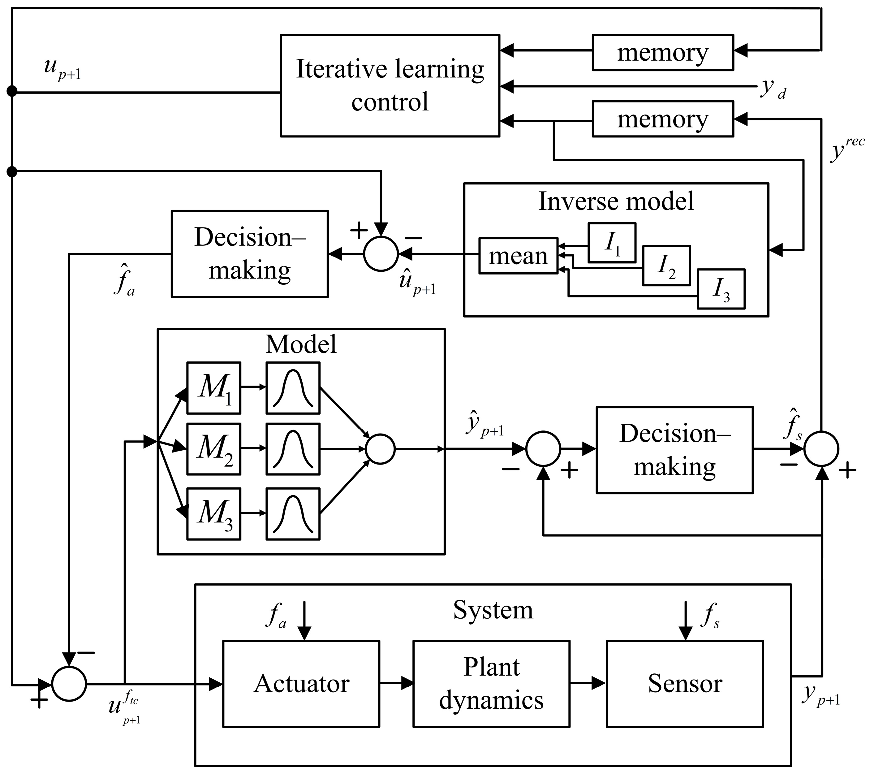
3.6. The Fault Diagnosis and Fault-Tolerant Control of the BBW System

In addition to braking redundancy, new energy vehicles must also integrate fault-tolerant control to ensure the reliability of the braking system. Fault diagnosis is the foundation of fault-tolerant control, enabling the timely identification of potential faults and providing precise information for corresponding control strategies. Faults in the brake-by-wire system often stem from system aging, which may lead to brake fluid leakage and even system failure.
To address this issue, Ref. [136] developed a fault diagnosis model based on discrete event systems (DESs). The model employs decentralized most-permissive observers to diagnose brake fluid leakage faults and uses virtual simulation technology to verify its effectiveness in fault localization and multi-fault scenarios. In [137], a data-driven fault diagnosis method combining a hydraulic control unit model with multivariate time-series modeling was proposed to estimate the wheel cylinder pressure. To improve generalization, a shifting data augmentation technique was applied to generate large datasets, and a cumulative sum (CUSUM) residual comparison approach was employed for fault detection and isolation. Compared with the traditional multilayer perceptron (MLP) and long short-term memory networks, this method reduces the dependency on large-scale real-world data, achieves a stronger generalization, improves the diagnostic accuracy, and lowers the root mean square error (RMSE) of fault diagnosis by 17%. In addition, Ref. [138] processed and analyzed friction signals from mechanical brakes and employed intelligent algorithms such as a SVM and a BP neural network to realize online fault diagnosis and prediction. The proposed method achieved a diagnostic accuracy of 95.2% and provided early warnings for severe faults caused by excessive frictional heat.
In terms of fault-tolerant control, Ref. [139] addressed the issue of system disturbances caused by in-wheel motor faults, including bias-type faults and the loss-of-effectiveness, by developing a robust fault-tolerant control strategy that combines terminal sliding mode control with cooperative game theory. This approach fully considers individual driver differences and demonstrates a strong adaptability to various fault types and driving styles, significantly improving the vehicle stability and robustness. Under inexperienced and experienced driver conditions, the vehicle stability is improved by 26.31% and 10.09%, respectively. Ref. [140] proposed an improved fault-tolerant hierarchical control method based on model predictive control. In the upper layer, sliding mode control generates a yaw moment to suppress system parameter disturbances. In the lower layer, an improved MPC reconstructs the torque distribution, enabling the coordinated control of four motors under motor fault conditions. This method enhances the robustness of the fault-tolerant control by mitigating the impact of motor fault uncertainties. The simulation results indicate that the proposed MPC achieves a superior control performance compared to the conventional MPC, reducing the yaw rate error and path deviation by at least 23.8% and 3.1%, respectively, under complex fault scenarios. Ref. [16] focused on circuit faults in switched reluctance motor (SRM) drives under regenerative braking in electric vehicles. The study established a coupled model of the braking system and the fault-tolerant SRM drive system and proposed a control strategy that addresses both open-circuit and short-circuit faults. This strategy uses traditional power converter circuits to replace the fault circuits of modular power converters, ensuring that the vehicle can maintain a normal braking performance even in the event of a fault. Furthermore, Ref. [141] proposed a hierarchical transient fault-tolerant control strategy with embedded intelligence and resilient coordination to handle node-level and system-level transient faults in the BBW system. The strategy adopts a feature-based detection method for rapid node-level fault recovery and applies a combination of sliding mode control and task reallocation strategies for system-level faults. The simulation and experimental results demonstrated the strategy’s effectiveness in addressing transient faults at different system levels in the automotive industry. Moreover, machine learning techniques can further enhance fault-tolerant control. Refs. [142,143] applied data-driven iterative learning control methods. Specifically, Ref. [142] developed a fault-tolerant iterative learning control method, as shown in Figure 11, which considers the system uncertainty and task repeatability under potential fault conditions. It integrates a state–space hybrid fault detection feedforward neural network, a fault isolation inverse neural network, and a static learning controller to compensate for sensor and actuator faults. Ref. [143] further improved the actuator fault tolerance by continuously updating control signals through an iterative learning strategy and using a hybrid neural network and inverse model integration method to adapt to changing operating conditions.

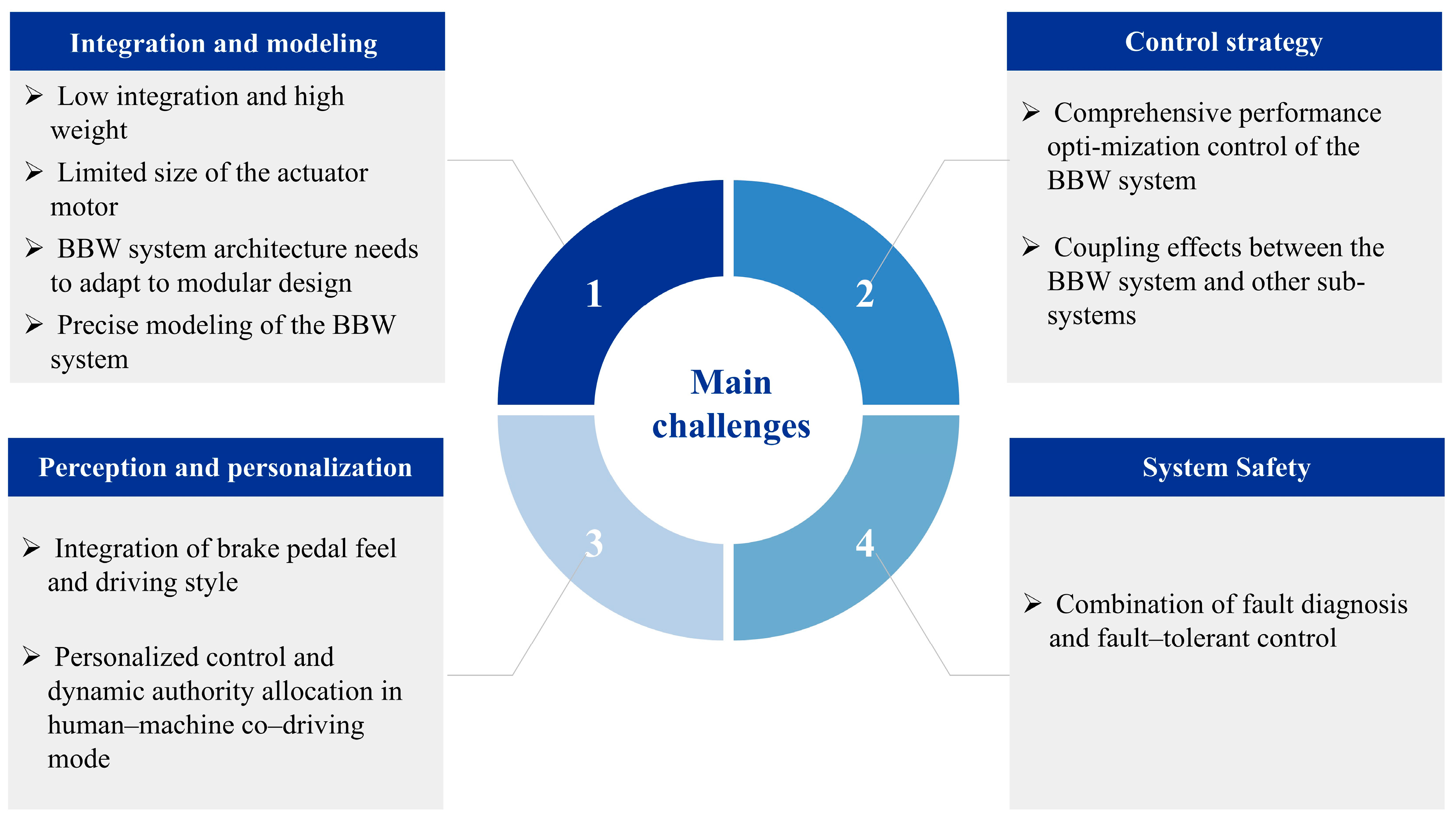
4. Challenges and Future Trends of the BBW System

With the continuous advancement of brake-by-wire (BBW) technology, the electro-hydraulic braking (EHB) system, as one of its core technologies, has already been widely applied in new energy vehicles. As a vital bridge connecting new energy vehicles with autonomous/unmanned driving technologies, the BBW system has achieved significant breakthroughs in key areas such as brake pressure control and regenerative braking energy recovery. However, as illustrated in Figure 12, it still faces numerous technical challenges. Based on a systematic review of the latest domestic and international research, this section will deeply analyze the core technical challenges confronting BBW systems in new energy vehicles from four aspects and explore future development trends, aiming to provide innovative insights and technical solutions to enhance system performance and accelerate industrial implementation. The specific content is as follows:
(1)
Hardware integration optimization and accurate modeling: Under the limited chassis space constraints of new energy vehicles, the BBW system has put forward higher requirements for hardware integration. At present, EHB is more mature than other BBW system technologies. However, because it relies on traditional hydraulic components, such as brake lines, master cylinders, and even the pump-driven accumulator, EHB requires the additional integration of hydraulic pumps and accumulators, and the overall system integration is lower and the weight is higher. In contrast, the EMB system offers better integration. However, the size of the executing motor is constrained due to the limited installation space of the wheels, making it difficult to provide sufficient braking torque. In addition, to meet the safety requirements of autonomous driving, redundant braking designs (such as EHB backup pipelines or EMB backup motors) inevitably increase the system weight and cost, which is not conducive to the lightweight design of new energy vehicles. Therefore, future research will focus on optimizing hardware integration to improve the spatial layout efficiency of BBW systems, reduce coordination difficulties between subsystems, and decrease the system size and weight, enabling the centralized management of upper-level control strategies. A key research direction will be the development of BBW system architectures that adapt to automotive modular (corner module) designs, ensuring a high integration while maintaining the braking performance. On the other hand, as the BBW system is a typical nonlinear electro-mechanical (or electro-mechanical–hydraulic) coupled system, it exhibits complex characteristics, such as nonlinear friction and time-varying parameters, during its operation. Accurate modeling must fully account for these factors to achieve an optimal control performance. Therefore, establishing mathematical models that can accurately reflect system characteristics will be the key to future research, and it is crucial for formulating and implementing better control strategies.
(2)
The optimization and upgrading of control strategies: The optimization and upgrading of braking control strategies are key to improving the overall performance of new energy vehicles. As a core component for ensuring driving safety, braking strategies should not only provide a fast response and high-precision control but also enable efficient regenerative braking to extend the vehicle range. In addition, the BBW system should ensure smooth braking transitions to deliver a more comfortable experience for drivers and passengers. However, as technical requirements in the industry continue to rise, traditional control strategies, such as PID and fuzzy control, have become insufficient to meet the current diversified development demands. It is urgent to introduce more advanced intelligent control algorithms to achieve technological breakthroughs. At the same time, there is a coupling effect between the BBW system and other X-by-wire chassis subsystems. Achieving a coordinated optimization of the safety, energy recovery efficiency, and ride comfort often requires the collaboration of multiple chassis subsystems, which can lead to conflicts among control functions and compromise the overall system performance. Therefore, future research on braking control strategies for new energy vehicles will focus on introducing more intelligent control algorithms, such as deep reinforcement learning algorithms, to coordinate the BBW system with other subsystems. This method aims to deliver a superior control performance compared to standalone BBW systems, ultimately achieving an optimal balance between braking safety, energy recovery efficiency, and driving comfort.
(3)
Pedal perception emulation and personalized control integrating driving styles: As a key component of the perception layer of the BBW system, pedal feel emulation control is gradually evolving toward a fully decoupled design. This means that the system uses independent simulation mechanisms to dynamically replicate the characteristics of traditional brake pedals, including pedal stroke damping and force feedback gradients, to ensure that the driver’s operating experience is consistent with traditional braking systems. However, due to individual differences among drivers, braking habits vary widely, and traditional pedal characteristics do not account for different driving styles. In addition, the current control architecture of ADASs still focuses on optimizing vehicle performance. In the human–machine co-driving mode, the dynamic allocation of control authority requires the further integration of driving style recognition and personalized control strategies. Therefore, future research on BBW systems should focus on establishing brake pedal perception standards that incorporate driving style characteristics, developing quantitative evaluation methods based on human–machine interactions and driving behavior patterns, and designing personalized control systems that enable intelligent matching between control strategies and individual driver behaviors, thereby comprehensively improving the personalization of the driving experience and the intelligence level of the human–machine interaction.
(4)
Fault diagnosis and fault-tolerant control integration architecture for the BBW system: Although traditional hardware redundancy schemes can improve system reliability, they also increase the cost, curb weight, and energy consumption of new energy vehicles. With the continuous development of BBW technology, such redundant designs will gradually be simplified or even completely replaced. However, the increasing electrification of new energy vehicles also brings higher fault risks, making fault-tolerant control systems more critical than ever. As a prerequisite for fault-tolerant control, fault diagnosis is essential to ensuring the stability of BBW systems. Whether sensor signal anomalies or actuator failures, such issues can lead to system performance degradation or functional failure, threatening driving safety. Traditional fault diagnosis methods, such as those based on fuzzy rules or state observers, can no longer cope with the highly nonlinear characteristics of BBW systems. In contrast, fault diagnosis technologies based on intelligent algorithms can more effectively identify complex fault patterns. Therefore, the future development focus will be on the deep integration of intelligent fault diagnosis algorithms based on multi-source information fusion and efficient fault-tolerant control strategies to significantly improve the reliability and safety of the BBW system.

5. Conclusions

The new energy vehicle industry is rapidly advancing toward electrification and intelligence. In this context, the BBW system, as a key technology replacing traditional hydraulic braking systems, has ushered in significant opportunities for technological innovation and industrialization. Based on a comprehensive review of the existing references, this paper systematically reviews the development of BBW technology in NEVs, including system classification, structural configurations, working principles, and representative products. It also provides an in-depth analysis of core technologies such as system design and modeling methods, braking force optimization and distribution strategies, precise actuator control, multi-system coordination, driver operation perception and intelligent decision-making, personalized control, and fault diagnosis and fault-tolerant control.
On this basis, this paper reviews the main technical challenges of the BBW system and provides insights into its future development. Specifically, the future development of BBW technology should focus on the following aspects:
(1)
Establishing mathematical models that accurately reflect system characteristics, laying the foundation for optimizing control strategies;
(2)
Adopting advanced intelligent control algorithms to enable more efficient coordination between the BBW system and other components of the X-by-wire chassis, achieving the collaborative optimization of safety, braking efficiency, and ride comfort;
(3)
Developing pedal feel emulation and personalized control strategies that incorporate driving style characteristics, achieving intelligent matching between control systems and driver behavior patterns;
(4)
Integrating multi-source information fusion with intelligent fault diagnosis algorithms and efficient fault-tolerant control strategies to improve system reliability and safety.
Breakthroughs in these technical directions will improve the overall performance of the BBW system in NEVs, provide safer and more reliable braking for intelligent driving systems, and promote the advancement of NEV intelligent technologies toward higher levels of autonomous driving.

Author Contributions

Writing—original draft, Z.C.; Supervision and funding acquisition, R.W.; Writing—review and editing, R.D.; Investigation, B.L.; Methodology, W.L.; Resources, D.S.; Validation, Z.G. All authors have read and agreed to the published version of the manuscript.

Funding

This work was supported by the National Key R&D Program of China (Grant No. 2023YFB2504500), the National Natural Science Foundation Project of China (Grant No. 52472410), and the Key R&D Program Project of Zhenjiang City (Grant No. ZD2022002).

Data Availability Statement

Data are contained within the article.

Conflicts of Interest

Author Bin Liu was employed by the company Changzhou Research and Development Center Co., Ltd. Author Zhongyang Guo was employed by the company Jiangsu Chaoli Electric Appliance Co., Ltd. The remaining authors declare that the research was conducted in the absence of any commercial or financial relationships that could be construed as a potential conflict of interest.

References

  1. Verma, S.; Sharma, A.; Tran, B.; Alahakoon, D. A systematic review of digital twins for electric vehicles. J. Traffic Transp. Eng. Engl. Ed. 2024, 11, 815–834. [Google Scholar] [CrossRef]
  2. Bei, X.R.; Yu, X.J.; Li, D.Q.; Sun, Q.L.; Yu, Y.H.; Wang, Y.Q.; Okonkwo, C.E.; Zhou, C. Heat source replacement strategy using catalytic infrared: A future for energy saving drying of fruits and vegetables. J. Food Sci. 2023, 88, 4827–4839. [Google Scholar] [CrossRef]
  3. Zhou, C.S.; Adeyanju, A.A.; Nwonuma, C.O.; Inyinbor, A.A.; Alejolowo, O.O.; Al-Hamayda, A.; Akinsemolu, A.; Onyeaka, H.; Olaniran, A.F. Physical field-assisted deep eutectic solvent processing: A green and water-saving extraction and separation technology. J. Food Sci. 2024, 89, 8248–8275. [Google Scholar] [CrossRef]
  4. Li, H.; Issaka, Z.; Jiang, Y.; Tang, P.; Chen, C. Overview of emerging technologies in sprinkler irrigation to optimize crop production. Int. J. Agric. Biol. Eng. 2019, 12, 1–9. [Google Scholar] [CrossRef]
  5. Tang, Q.; Yang, Y.; Luo, C.; Yang, Z.; Fu, C. A novel electro-hydraulic compound braking system coordinated control strategy for a four-wheel-drive pure electric vehicle driven by dual motors. Energy 2022, 241, 122750. [Google Scholar] [CrossRef]
  6. Zhu, X.Y.; Chikangaise, P.; Shi, W.D.; Chen, W.H.; Yuan, S.Q. Review of intelligent sprinkler irrigation technologies for remote autonomous system. Int. J. Agric. Biol. Eng. 2018, 11, 23–30. [Google Scholar] [CrossRef]
  7. Issaka, Z.; Li, H.; Jiang, Y.; Tang, P.; Chen, C.; Darko, R.O. Hydraulic performance characteristics of impact sprinkler with a fixed water dispersion device. Int. J. Agric. Biol. Eng. 2018, 11, 104–112. [Google Scholar] [CrossRef]
  8. Aguilar-Alvarez, P.; Valencia-Palomo, G.; Lopez-Estrada, F.-R.; Zepeda-Hernandez, J.A.; Lopez-Perez, M.-D.-J.; Santos-Ruiz, I.; Garcia-Ramos, O.-Y. Instrumentation and dynamic characterization of a commercial electric vehicle for rural public transport. IEEE Access 2023, 11, 12639–12647. [Google Scholar] [CrossRef]
  9. Zhang, Q.; Wang, J.; Zhang, Y.; Zhang, R.; Jin, L.; Yin, G. Key Technologies and Research Progress of Brake-by-wire System for Intelligent Electric Vehicles. J. Mech. Eng. 2024, 60, 339–365. [Google Scholar]
  10. Dua, R. Net-zero transport dialogue: Emerging developments and the puzzles they present. Energy Sustain. Dev. 2024, 82, 101516. [Google Scholar] [CrossRef]
  11. Timilsina, R.R.; Zhang, J.; Rahut, D.B.; Patradool, K.; Sonobe, T. Global drive toward net-zero emissions and sustainability via electric vehicles: An integrative critical review. Energy Ecol. Environ. 2025, 10, 125–144. [Google Scholar] [CrossRef]
  12. Cao, Z.; Yang, X.; Zhu, X.; Xia, Y. Optimal design and experimental study of comb-type disc magnetorheological brake. Measurement 2024, 229, 114458. [Google Scholar] [CrossRef]
  13. Zhou, X.; Wu, G.; Wang, C.; Zhang, R.; Shi, S.; Zhao, W. Cooperative optimization of energy recovery and braking feel based on vehicle speed prediction under downshifting conditions. Energy 2024, 301, 131699. [Google Scholar] [CrossRef]
  14. Cao, W.; He, Z.; Cheng, A.; Zhao, Q.; Tan, H. Multi-bandwidth observer-based adaptive robust pressure control for electro-hydraulic brake system with uncertainties and measurement noise. Control Eng. Pract. 2024, 153, 106122. [Google Scholar] [CrossRef]
  15. Amin, A.A.; Mubarak, A.; Waseem, S. Application of physics-informed neural networks in fault diagnosis and fault-tolerant control design for electric vehicles: A review. Measurement 2025, 246, 116728. [Google Scholar] [CrossRef]
  16. Xing, C.; Zhu, Y.; Wang, J.; Lin, Y. Fault-tolerant control of in-wheel switched reluctance motor drive systems for vehicles under regenerative braking condition. J. Power Electron. 2024, 24, 1766–1777. [Google Scholar] [CrossRef]
  17. Li, Y.M.; Liu, Y.B.; Ji, K.Z.; Zhu, R.H. A Fault Diagnosis Method for a Differential Inverse Gearbox of a Crawler Combine Harvester Based on Order Analysis. Agriculture 2022, 12, 1300. [Google Scholar] [CrossRef]
  18. Hao, S.H.; Tang, Z.; Guo, S.B.; Ding, Z.; Su, Z. Model and Method of Fault Signal Diagnosis for Blockage and Slippage of Rice Threshing Drum. Agriculture 2022, 12, 1968. [Google Scholar] [CrossRef]
  19. Zhao, X.; Xiong, L.; Zhuo, G.; Tian, W.; Li, J.; Shu, Q.; Zhao, X.; Xu, G. A Review of One-Box Electro-Hydraulic Braking System: Architecture, Control, and Application. Sustainability 2024, 16, 1049. [Google Scholar] [CrossRef]
  20. Yang, C.; Sun, T.; Wang, W.; Li, Y.; Zhang, Y.; Zha, M. Regenerative braking system development and perspectives for electric vehicles: An overview. Renew. Sustain. Energy Rev. 2024, 198, 114389. [Google Scholar] [CrossRef]
  21. Hamada, A.T.; Orhan, M.F. An overview of regenerative braking systems. J. Energy Storage 2022, 52, 105033. [Google Scholar] [CrossRef]
  22. Zhang, L.; Wang, Q.; Chen, J.; Wang, Z.-P.; Li, S.-H. Brake-by-wire system for passenger cars: A review of structure, control, key technologies, and application in X-by-wire chassis. Etransportation 2023, 18, 100292. [Google Scholar] [CrossRef]
  23. Ji, Y.; Zhang, J.; He, C.; Ma, R.; Hou, X.; Hu, H. Constraint performance pressure tracking control with asymmetric continuous friction compensation for booster based brake-by-wire system. Mech. Syst. Signal Process. 2022, 174, 109083. [Google Scholar] [CrossRef]
  24. Nakamura, E.; Soga, M.; Sakai, A.; Otomo, A.; Kobayashi, T. Development of Electronically Controlled BrakeSystem for Hybrid Vehicle. In Proceedings of the SAE 2002 World Congress & Exhibition, Detroit, MI, USA, 4–7 March 2002. [Google Scholar]
  25. Stoll, U. Sensotronic brake control (SBC)—The electro-hydraulic brake from Mercedes-Benz. In Proceedings of the 10th International Congress on Electronic Systems for Vehicles, Baden Baden, Germany, 1 January 2003; pp. 675–685. [Google Scholar]
  26. Savitski, D.; Ivanov, V.; Schleinin, D.; Augsburg, L.; Pütz, T.; Lee, C.F. Advanced control functions of decoupled electro-hydraulic brake system. In Proceedings of the 2016 IEEE 14th International Workshop on Advanced Motion Control (AMC), Auckland, New Zealand, 22–24 April 2016; pp. 310–317. [Google Scholar] [CrossRef]
  27. Riese, C.; Gauterin, F. Evaluation of a state of the art hydraulic brake system with regard to future requirements. SAE Int. J. Passeng. Cars Mech. Syst 2016, 9, 1172–1183. [Google Scholar] [CrossRef]
  28. Oshima, T.; Fujiki, N.; Nakao, S.; Kimura, T.; Ohtani, Y.; Ueno, K. Development of an electrically driven intelligent brakesystem. SAE Int. J. Passeng. Cars Mech. Syst. 2011, 4, 399–405. [Google Scholar] [CrossRef]
  29. Bauer, U.; Brand, M.; Maucher, T. Integrated Power Brake–modular set extension for highlyautomated driving. In Proceedings of the 8th International Munich Chassis Symposium 2017, Vieweg, Wiesbaden, 21 September 2017; pp. 693–710. [Google Scholar]
  30. Schmid, B.; Grunwald, F.; Lehmann, S.; Acker, H. Position Sensor for Brake System Designed for Energy Recuperation. In Advanced Microsystems for Automotive Applications 2013; Springer: Berlin/Heidelberg, Germany, 2013; pp. 285–299. [Google Scholar]
  31. Wang, J.; Chen, R. An improved finite element model for the hydraulic analysis of drip irrigation subunits considering local emitter head loss. Irrig. Sci. 2020, 38, 147–162. [Google Scholar] [CrossRef]
  32. Chen, S.R.; Ding, H.T.; Tang, Z.; Hao, S.H.; Zhao, Y.F. Influence of rice straw forming factors on ring die wear and improved wear prediction model during briquetting. Biosyst. Eng. 2022, 214, 122–137. [Google Scholar] [CrossRef]
  33. Ma, Z.; Zhu, Y.L.; Chen, S.R.; Traore, S.N.; Li, Y.M.; Xu, L.Z.; Shi, M.; Zhang, Q. Field Investigation of the Static Friction Characteristics of High-Yielding Rice during Harvest. Agriculture 2022, 12, 327. [Google Scholar] [CrossRef]
  34. Wang, J.; Yang, T.; Wei, T.; Chen, R.; Yuan, S.Q. Experimental determination of local head loss of non-coaxial emitters in thin-wall lay-flat polyethylene pipes. Biosyst. Eng. 2020, 190, 71–86. [Google Scholar] [CrossRef]
  35. Zhang, Z.; Yang, K.; Nie, M.; Ma, C.; Tan, D.; Huang, Z. Design and Verification of a novel Synchronous Force-Increasing Disk Electro-Mechanical Brake Actuator for Pure Electric Trucks. Int. J. Automot. Technol. 2025. [Google Scholar] [CrossRef]
  36. Xiao, F.; Gong, X.; Lu, Z.; Qian, L.; Zhang, Y.; Wang, L. Design and Control of New Brake-by-Wire Actuator for Vehicle Based on Linear Motor and Lever Mechanism. IEEE Access 2021, 9, 95832–95842. [Google Scholar] [CrossRef]
  37. Durali, L.; Khajepour, A.; Jeon, S. Design and optimization of a cam-actuated electrohydraulic brake system. Proc. Inst. Mech. Eng. Part D J. Automob. Eng. 2018, 232, 909–920. [Google Scholar] [CrossRef]
  38. Yan, Z.; Chen, X.; Yan, M.; Hang, P. Design and optimization of a novel Electronic Mechanical Brake Actuator Based on Cam. Actuators 2023, 12, 329. [Google Scholar] [CrossRef]
  39. Park, H.; Choi, S.B. Development of a Sensorless Control Method for a Self-Energizing Brake System Using Noncircular Gears. IEEE Trans. Control Syst. Technol. 2013, 21, 1328–1339. [Google Scholar] [CrossRef]
  40. Ahmad, F.; Hudha, K.; Mazlan, S.A.; Jamaluddin, H.; Zamzuri, H.; Abd Kadir, Z.; Aparow, V.R. Modelling and Control of a Fixed Calliper-Based Electronic Wedge Brake. Stroj. Vestn. J. Mech. Eng. 2017, 63, 181–190. [Google Scholar] [CrossRef]
  41. Li, C.; Zhang, J.; Hou, X.; Ji, Y.; Han, J.; He, C.; Hao, J. A Novel Double Redundant Brake-by-Wire System for High Automation Driving Safety: Design, Optimization and Experimental Validation. Actuators 2021, 10, 287. [Google Scholar] [CrossRef]
  42. Yuan, C.; He, Z.; Shen, J.; Chen, L.; Cai, Y.; He, Y.; Weng, S.; Yuan, Y.; Gong, Y. Design, modeling, and simulation of dual-source redundant braking system. Proc. Inst. Mech. Eng. Part D J. Automob. Eng. 2024, 238, 18–31. [Google Scholar] [CrossRef]
  43. Liu, Q.; Qin, C.; Fu, Y.Q.; Lin, D.P.; Liao, K.X. Vehicle Electromechanical Brake System and Vehicle with Same. CN Patent 201910912660.X, 26 March 2021. (In Chinese). [Google Scholar]
  44. Lee, K.J.; Ki, Y.H.; Cheon, J.S.; Hwang, G.; Ahn, H.S. Approach to functional safety-compliant ECU design for electro-mechanical brake systems. Int. J. Automot. Technol. 2014, 15, 325–332. [Google Scholar] [CrossRef]
  45. Shi, X.; Krishnamurthy, M. Survivable operation of induction machine drives with smooth transition strategy for EV applications. IEEE J. Emerg. Sel. Top. Power Electron. 2014, 2, 609–617. [Google Scholar]
  46. Foshati, A.; Ejlali, A. Enhancing sensor fault tolerance in automotive systems with cost-effective cyber redundancy. IEEE Trans. Intell. Veh. 2024, 9, 4794–4803. [Google Scholar] [CrossRef]
  47. Kang, W.S.; Choi, C.K.; Yoo, H.H. Stochastic modeling of friction force and vibration analysis of a mechanical system using the model. J. Mech. Sci. Technol. 2015, 29, 3645–3652. [Google Scholar] [CrossRef]
  48. Houhua, J.; Qinggan, L.; Mingqi, L. Friction Modeling and Control Compensation for Electromechanical Braking Systems. In Proceedings of the 2024 8th CAA International Conference on Vehicular Control and Intelligence (CVCI), Chongqing, China, 25–27 October 2024; pp. 1–6. [Google Scholar]
  49. Wang, Q.; Wang, Z.; Mo, J.; Zhu, S.; Gou, Q. Evaluation of the dynamic behaviors of a train braking system considering disc-block interface characteristics. Mech. Syst. Signal Process. 2023, 192, 110234. [Google Scholar] [CrossRef]
  50. Beerens, R.; Bisoffi, A.; Zaccarian, L.; Nijmeijer, H.; Heemels, M.; van de Wouw, N. Reset PID Design for Motion Systems With Stribeck Friction. IEEE Trans. Control Syst. Technol. 2022, 30, 294–310. [Google Scholar] [CrossRef]
  51. El-bakkouri, J.; Mansouri, A.; Ouadi, H.; El Aoumari, A.; El Khlifi, Y.; Giri, F. Robust Braking Pressure Control for an Electrohydraulic Brake System under Friction and Disturbance Conditions. In Proceedings of the Conference Robust Braking Pressure Control for an Electrohydraulic Brake System under Friction and Disturbance Conditions, Rabat, Morocco, 8 August 2024; Volume 58, pp. 539–544. [Google Scholar]
  52. Yao, J.; Deng, W.; Jiao, Z. Adaptive control of hydraulic actuators with LuGre model-based friction compensation. IEEE Trans. Ind. Electron. 2015, 62, 6469–6477. [Google Scholar] [CrossRef]
  53. Cao, L.; Downey, A.; Laflamme, S.; Taylor, D.; Ricles, J. Variable friction device for structural control based on duo-servo vehicle brake: Modeling and experimental validation. J. Sound Vib. 2015, 348, 41–56. [Google Scholar] [CrossRef]
  54. Zhou, H.; Wang, G.; Ding, Y.; Yang, J.; Liang, C.; Fu, J. Effect of Friction Model and Tire Maneuvering on Tire-Pavement Contact Stress. Adv. Mater. Sci. Eng. 2015, 2015, 632647. [Google Scholar] [CrossRef]
  55. Zhao, J.; Du, J.; Zhu, B.; Chen, Z. Adaptive Dual-Loop Pressure Control for an Integrated Electro-Hydraulic Brake System Considering Uncertain Nonlinear Characteristics. IEEE Trans. Transp. Electrif. 2024, 10, 9428–9440. [Google Scholar] [CrossRef]
  56. Sun, P.; Trigell, A.S.; Drugge, L.; Jerrelind, J. Energy efficiency and stability of electric vehicles utilising direct yaw moment control. Veh. Syst. Dyn. 2022, 60, 930–950. [Google Scholar] [CrossRef]
  57. Cheng, S.; Li, L.; Liu, C.-Z.; Wu, X.; Fang, S.-N.; Yong, J.-W. Robust LMI-Based H-Infinite Controller Integrating AFS and DYC of Autonomous Vehicles With Parametric Uncertainties. IEEE Trans. Syst. Man Cybern. Syst. 2021, 51, 6901–6910. [Google Scholar] [CrossRef]
  58. Liu, H.; Yan, S.C.; Shen, Y.; Li, C.H.; Zhang, Y.F.; Hussain, F. Model predictive control system based on direct yaw moment control for 4WID self-steering agriculture vehicle. Int. J. Agric. Biol. Eng. 2021, 14, 175–181. [Google Scholar] [CrossRef]
  59. Xiong, F.; Lan, F.; Chen, J.; Yang, Y. Investigation into Improvement for Anti-Rollover Propensity of SUV. Chin. J. Mech. Eng. 2017, 30, 698–710. [Google Scholar] [CrossRef]
  60. Tang, M.; Zhang, X. Optimal Regenerative Braking Control Strategy for Electric Vehicles Based on Braking Intention Recognition and Load Estimation. IEEE Trans. Veh. Technol. 2024, 73, 3378–3392. [Google Scholar] [CrossRef]
  61. Sun, H.; Wang, H.; Zhao, X. Line Braking Torque Allocation Scheme for Minimal Braking Loss of Four-Wheel-Drive Electric Vehicles. IEEE Trans. Veh. Technol. 2019, 68, 180–192. [Google Scholar] [CrossRef]
  62. Hosseini Salari, A.; Mirzaeinejad, H.; Fooladi Mahani, M. A new control algorithm of regenerative braking management for energy efficiency and safety enhancement of electric vehicles. Energy Convers. Manag. 2023, 276, 116564. [Google Scholar] [CrossRef]
  63. Wu, J.; Liu, H.; Ren, X.; Nie, S.; Qin, Y.; Han, L. A multi-objective optimization approach for regenerative braking control in electric vehicles using MPE-SAC algorithm. Energy 2025, 318, 134586. [Google Scholar] [CrossRef]
  64. Ji, F.; Pan, Y.; Zhou, Y.; Du, F.; Zhang, Q.; Li, G. Energy recovery based on pedal situation for regenerative braking system of electric vehicle. Veh. Syst. Dyn. 2020, 58, 144–173. [Google Scholar] [CrossRef]
  65. Geng, C.; Ning, D.; Guo, L.; Xue, Q.; Mei, S. Simulation Research on Regenerative Braking Control Strategy of Hybrid Electric Vehicle. Energies 2021, 14, 2202. [Google Scholar] [CrossRef]
  66. Zhang, Y.; Wang, W.; Xiang, C.; Yang, C.; Peng, H.; Wei, C. A swarm intelligence-based predictive regenerative braking control strategy for hybrid electric vehicle. Veh. Syst. Dyn. 2022, 60, 973–997. [Google Scholar] [CrossRef]
  67. Yang, Y.; Tang, Q.; Bolin, L.; Fu, C. Dynamic Coordinated Control for Regenerative Braking System and Anti-Lock Braking System for Electrified Vehicles Under Emergency Braking Conditions. IEEE Access 2020, 8, 172664–172677. [Google Scholar] [CrossRef]
  68. Zhao, L.; Ye, M.; Xu, X. Intelligent optimization of EV comfort based on a cooperative braking system. Proc. Inst. Mech. Eng. Part D J. Automob. Eng. 2021, 235, 2904–2916. [Google Scholar] [CrossRef]
  69. Zhang, R.; Zhao, W.; Wang, C.; Tai, K. Research on personalized control strategy of EHB system for consistent braking feeling considering driving behaviors. Energy 2024, 293, 130568. [Google Scholar] [CrossRef]
  70. Cui, L.F.; Mao, H.P.; Xue, X.Y.; Ding, S.M.; Qiao, B.Y. Optimized design and test for a pendulum suspension of the crop spray boom in dynamic conditions based on a six DOF motion simulator. Int. J. Agric. Biol. Eng. 2018, 11, 76–85. [Google Scholar]
  71. Cui, L.F.; Xue, X.Y.; Le, F.X.; Mao, H.P.; Ding, S.M. Design and experiment of electro hydraulic active suspension for controlling the rolling motion of spray boom. Int. J. Agric. Biol. Eng. 2019, 12, 72–81. [Google Scholar] [CrossRef]
  72. Li, J.Y.; Nie, Z.Y.; Chen, Y.F.; Ge, D.Q.; Li, M.Q. Development of Boom Posture Adjustment and Control System for Wide Spray Boom. Agriculture 2023, 13, 2162. [Google Scholar] [CrossRef]
  73. Zhang, J.; Sun, W.; Liu, Z.; Zeng, M. Comfort braking control for brake-by-wire vehicles. Mech. Syst. Signal Process. 2019, 133, 106255. [Google Scholar] [CrossRef]
  74. Zhang, J.; Yang, Y.; Hu, M.; Yang, Z.; Fu, C. Longitudinal–vertical comprehensive control for four-wheel drive pure electric vehicle considering energy recovery and ride comfort. Energy 2021, 236, 121417. [Google Scholar] [CrossRef]
  75. Zhou, Z.; Wang, Y.; Zhou, G.; Nam, K.; Ji, Z.; Yin, C. A Twisted Gaussian Risk Model Considering Target Vehicle Longitudinal-Lateral Motion States for Host Vehicle Trajectory Planning. IEEE Trans. Intell. Transp. Syst. 2023, 24, 13685–13697. [Google Scholar] [CrossRef]
  76. Lai, F.; Huang, C.; Ye, X. Analysis of Vehicle Driving Stability based on Longitudinal-lateral and Vertical Unified Dynamics Model. Int. J. Automot. Technol. 2022, 23, 73–87. [Google Scholar] [CrossRef]
  77. Zhou, H.; Jia, F.; Jing, H.; Liu, Z.; Guvenc, L. Coordinated Longitudinal and Lateral Motion Control for Four Wheel Independent Motor-Drive Electric Vehicle. IEEE Trans. Veh. Technol. 2018, 67, 3782–3790. [Google Scholar] [CrossRef]
  78. Zhang, L.; Liu, Q.; Wang, Z. Electro-hydraulic brake control for improved ride comfort in four-wheel-independently-actuated electric vehicles. J. Mech. Eng. 2020, 56, 125–134. [Google Scholar]
  79. Zhang, R.; Zhao, W.; Wang, C.; Xu, C.; Wu, G. A μ-H control strategy for decreasing torque fluctuation of electro-hydraulic integrated braking system in mode switching. Asian J. Control 2023, 25, 4268–4290. [Google Scholar] [CrossRef]
  80. Liu, Y.; Gao, D.; Zhai, K.; Huang, Q.; Chen, Z.; Zhang, Y. Coordinated control strategy for braking and shifting for electric vehicle with two-speed automatic transmission. eTransportation 2022, 13, 100188. [Google Scholar] [CrossRef]
  81. Jo, C.; Ko, J.; Yeo, H.; Yeo, T.; Hwang, S.; Kim, H. Cooperative regenerative braking control algorithm for an automatic-transmission-based hybrid electric vehicle during a downshift. Proc. Inst. Mech. Eng. Part D J. Automob. Eng. 2012, 226, 457–467. [Google Scholar] [CrossRef]
  82. Yang, Y.; Wang, C.; Zhang, Q.; He, X. Torque Coordination Control during Braking Mode Switch for a Plug-in Hybrid Electric Vehicle. Energies 2017, 10, 1684. [Google Scholar] [CrossRef]
  83. Wu, D.M.; Ding, H.T.; Guo, K.H.; Wang, Z.Q. Experiment Reasearch on the PressureFollowing Control of Electro-Hydraulic Braking System. SAE Tech. Pap. 2014. [Google Scholar] [CrossRef]
  84. Li, C.Q.; Wu, J.G.; Pan, X.Y.; Dou, H.J.; Zhao, X.G.; Gao, Y.Y.; Yang, S.; Zhai, C. Design and Experiment of a Breakpoint Continuous Spraying System for Automatic-Guidance Boom Sprayers. Agriculture 2023, 13, 2203. [Google Scholar] [CrossRef]
  85. Zhu, Y.Y.; Cui, B.B.; Yu, Z.L.; Gao, Y.Y.; Wei, X.H. Tillage Depth Detection and Control Based on Attitude Estimation and Online Calibration of Model Parameters. Agriculture 2024, 14, 2130. [Google Scholar] [CrossRef]
  86. Yang, Y.; Li, G.; Zhang, Q. A Pressure-Coordinated Control for Vehicle Electro-Hydraulic Braking Systems. Energies 2018, 11, 2336. [Google Scholar] [CrossRef]
  87. Wang, W.; Wu, Y.; Shi, J.; Li, L. Electronic hydraulic brake power system control strategy based on driver intention recognition. J. Jilin Univ. Eng. Technol. Ed. 2021, 51, 406–413. [Google Scholar]
  88. Song, X.H.; Li, H.; Chen, C.; Xia, H.M.; Zhang, Z.Y.; Tang, P. Design and Experimental Testing of a Control System for a Solid-Fertilizer-Dissolving Device Based on Fuzzy PID. Agriculture 2022, 12, 1382. [Google Scholar] [CrossRef]
  89. Chen, Y.X.; Chen, L.; Wang, R.C.; Xu, X.; Shen, Y.J.; Liu, Y.L. Modeling and test on height adjustment system of electrically-controlled air suspension for agricultural vehicles. Int. J. Agric. Biol. Eng. 2016, 9, 40–47. [Google Scholar]
  90. Wei, L.; Liu, Y.; Wang, X.; Liu, Z.; Li, L. Pressure Control Strategy for Brake by Wire Systems Based on Hierarchical Structure. J. Mech. Eng. 2024, 60, 487–496. [Google Scholar]
  91. Sun, J.L.; Wang, Z.; Ding, S.H.; Xia, J.; Xing, G.Y. Adaptive disturbance observer-based fixed time nonsingular terminal sliding mode control for path-tracking of unmanned agricultural tractors. Biosyst. Eng. 2024, 246, 96–109. [Google Scholar] [CrossRef]
  92. Li, J.Y.; Shang, Z.J.; Li, R.F.; Cui, B.B. Adaptive Sliding Mode Path Tracking Control of Unmanned Rice Transplanter. Agriculture 2022, 12, 1225. [Google Scholar] [CrossRef]
  93. Wang, R.C.; Zhang, K.Q.; Ding, R.K.; Jiang, Y.; Jiang, Y.Y. A Novel Hydraulic Interconnection Design and Sliding Mode Synchronization Control of Leveling System for Crawler Work Machine. Agriculture 2025, 15, 137. [Google Scholar] [CrossRef]
  94. Shi, Q.; He, L. A Model Predictive Control Approach for Electro-Hydraulic Braking by Wire. IEEE Trans. Ind. Inform. 2023, 19, 1380–1388. [Google Scholar] [CrossRef]
  95. Lu, E.; Xue, J.L.; Chen, T.T.; Jiang, S. Robust Trajectory Tracking Control of an Autonomous Tractor-Trailer Considering Model Parameter Uncertainties and Disturbances. Agriculture 2023, 13, 869. [Google Scholar] [CrossRef]
  96. Shan, T.; Li, L.; Wu, X.; Cheng, S. Pressure control based on reinforcement learning strategy of the pneumatic relays for an electric-pneumatic braking system. Proc. Inst. Mech. Eng. Part D J. Automob. Eng. 2023, 237, 2664–2675. [Google Scholar] [CrossRef]
  97. Zhao, Y.; Yang, Y.; Wu, X.; Tao, X. Research on accurate modeling and control for pneumatic electric braking system of commercial vehicle based on multi-dynamic parameters measurement. Proc. Inst. Mech. Eng. Part D J. Automob. Eng. 2023, 237, 803–815. [Google Scholar] [CrossRef]
  98. Zhu, B.; Zheng, Y.; Zhao, J.; Du, J.; Chen, Z.; Chen, Z.; Li, J.; Hao, W. Wheel Cylinder Pressure Control Strategy for Integrated Brake-by-wire System Based on Motor-solenoid Valve Coordinated Fluid Replenishment Logic. China J. Highw. Transp. 2024, 37, 289–300. [Google Scholar]
  99. Ma, C.; Wang, X.; Xu, T.; Wang, J.; Feng, P. Research on a novel electro-hydraulic brake system and pedal feel control strategy. Proc. Inst. Mech. Eng. Part D J. Automob. Eng. 2023, 237, 1681–1694. [Google Scholar] [CrossRef]
  100. Feng, L.; Sun, X.; Tian, X.; Diao, K. Direct Torque Control With Variable Flux for an SRM Based on Hybrid Optimization Algorithm. IEEE Trans. Power Electron. 2022, 37, 6688–6697. [Google Scholar] [CrossRef]
  101. Wu, Z.; Yang, Z.; Ding, K.; He, G. Transfer Mechanism Analysis of Injected Voltage Harmonic and its Effect on Current Harmonic Regulation in FOC PMSM. IEEE Trans. Power Electron. 2022, 37, 820–829. [Google Scholar] [CrossRef]
  102. Elgbaily, M.; Anayi, F.; Alshbib, M.M. A Combined Control Scheme of Direct Torque Control and Field-Oriented Control Algorithms for Three-Phase Induction Motor: Experimental Validation. Mathematics 2022, 10, 3842. [Google Scholar] [CrossRef]
  103. Hazem, H.; Fernando, S. Performance Comparison of Field-oriented Control, Direct Torque Control, and Model-predictive Control for SynRMs. Chin. J. Electr. Eng. 2022, 8, 24–37. [Google Scholar]
  104. Ali, M.M.; Xu, W.; Junejo, A.K.; Elmorshedy, M.F.; Tang, Y. One New Super-Twisting Sliding Mode Direct Thrust Control for Linear Induction Machine Based on Linear Metro. IEEE Trans. Power Electron. 2022, 37, 795–805. [Google Scholar] [CrossRef]
  105. Gillmeier, K.; Schuettke, T.; Diederichs, F.; Miteva, G.; Spath, D. Combined Driver Distraction and Intention Algorithm for Maneuver Prediction and Collision Avoidance. In Proceedings of the 2018 IEEE International Conference on Vehicular Electronics and Safety (ICVES), Madrid, Spain, 12–14 September 2018; pp. 1–6. [Google Scholar]
  106. Cui, B.B.; Cui, X.Y.; Wei, X.H.; Zhu, Y.Y.; Ma, Z.; Zhao, Y.; Liu, Y. Design and Testing of a Tractor Automatic Navigation System Based on Dynamic Path Search and a Fuzzy Stanley Model. Agriculture 2024, 14, 2136. [Google Scholar] [CrossRef]
  107. Chandio, F.A.; Li, Y.M.; Xu, L.Z.; Ma, Z.; Ahmad, F.; Cuong, D.M.; Lakhiar, I.A. Predicting 3D forces of disc tool and soil disturbance area using fuzzy logic model under sensor based soil-bin. Int. J. Agric. Biol. Eng. 2020, 13, 77–84. [Google Scholar] [CrossRef]
  108. Chang, X.H.; Huang, X.Y.; Xu, W.D.; Tian, X.Y.; Wang, C.Q.; Wang, L.; Yu, S. Monitoring of dough fermentation during Chinese steamed bread processing by near-infrared spectroscopy combined with spectra selection and supervised learning algorithm. J. Food Process Eng. 2021, 44, e13783. [Google Scholar] [CrossRef]
  109. Chen, Y.; Lin, M.W.; Yu, Z.; Sun, W.H.; Fu, W.G.; He, L. Enhancing cotton irrigation with distributional actor-critic reinforcement learning. Agric. Water Manag. 2025, 307, 109194. [Google Scholar] [CrossRef]
  110. Zhou, X.; Jun, S.; Yan, T.; Bing, L.; Hang, Y.Y.; Quansheng, C. Hyperspectral technique combined with deep learning algorithm for detection of compound heavy metals in lettuce. Food Chem. 2020, 321, 126503. [Google Scholar] [CrossRef]
  111. Li, X.; Zhang, X. Recognition Method of Braking Intention of Electric Vehicles Based on ABC-SVM Algorithm. China Mech. Eng. 2021, 32, 2125–2135. [Google Scholar]
  112. Zheng, H.; Ma, S.; Fang, L.; Zhao, W.; Zhu, T. Braking intention recognition algorithm based on electronic braking system in commercial vehicles. Int. J. Heavy Veh. Syst. 2019, 26, 268–290. [Google Scholar] [CrossRef]
  113. Yang, W.; Liu, J.; Zhou, K.; Zhang, Z.; Qu, X. An Automatic Emergency Braking Model considering Driver’s Intention Recognition of the Front Vehicle. J. Adv. Transp. 2020, 2020, 5172305. [Google Scholar] [CrossRef]
  114. Wang, S.; Zhao, X.; Yu, Q.; Yuan, T. Identification of Driver Braking Intention Based on Long Short-Term Memory (LSTM) Network. IEEE Access 2020, 8, 180422–180432. [Google Scholar] [CrossRef]
  115. Jiang, K.; Yang, W.; Huang, S. LaTAS-F: Locality-aware transformer architecture search with multi-source fusion for driver continuous braking intention inference. Expert Syst. Appl. 2024, 242, 122719. [Google Scholar] [CrossRef]
  116. Diederichs, F.; Schuettke, T.; Spath, D. IEEE Driver Intention Algorithm for Pedestrian Protection and Automated Emergency Braking Systems. In Proceedings of the Conference Driver Intention Algorithm for Pedestrian Protection and Automated Emergency Braking Systems, Gran Canaria, Spain, 15–18 September 2015; pp. 1049–1054. [Google Scholar]
  117. Ju, J.; Bi, L.; Feleke, A.G. Noninvasive neural signal-based detection of soft and emergency braking intentions of drivers. Biomed. Signal Process. Control 2022, 72, 103330. [Google Scholar] [CrossRef]
  118. Liu, Y.; Liang, X.; Yu, Y.; Sun, J.; Hu, J.; Liu, Y.; Zeng, L.-L.; Zhou, Z.; Hu, D. Recognizing drivers’ turning intentions with EEG and eye movement. Biomed. Signal Process. Control 2025, 101, 107218. [Google Scholar] [CrossRef]
  119. Qu, X.; Zhang, J.; Qu, L. Structure design and optimization of a disc-drum hybrid magnetorheological device for pedal force control. J. Automot. Saf. Energy 2023, 14, 698–706. [Google Scholar]
  120. Caliskan, U.; Apaydin, A.; Otaran, A.; Patoglu, V. A Series Elastic Brake Pedal to Preserve Conventional Pedal Feel under Regenerative Braking. In Proceedings of the 2018 IEEE/RSJ International Conference on Intelligent Robots and Systems (IROS), Madrid, Spain, 1–5 October 2018; pp. 1367–1373. [Google Scholar]
  121. Wang, D.; Wang, B.; Zi, B.; Bai, X.; Chen, W. Development and Control of a Magnetorheological Damper-Based Brake Pedal Simulator for Vehicle Brake-by-Wire Systems. Chin. J. Mech. Eng. 2022, 35, 136. [Google Scholar] [CrossRef]
  122. Huang, X.Y.; Pan, S.H.; Sun, Z.Y.; Ye, W.T.; Aheto, J.H. Evaluating quality of tomato during storage using fusion information of computer vision and electronic nose. J. Food Process Eng. 2018, 41, e12832. [Google Scholar] [CrossRef]
  123. Chen, Y.; Yu, Z.; Han, Z.X.; Sun, W.H.; He, L. A Decision-Making System for Cotton Irrigation Based on Reinforcement Learning Strategy. Agronomy 2024, 14, 11. [Google Scholar] [CrossRef]
  124. Cheng, J.H.; Sun, J.; Yao, K.S.; Xu, M.; Tian, Y.; Dai, C.X. A decision fusion method based on hyperspectral imaging and electronic nose techniques for moisture content prediction in frozen-thawed pork. Lwt Food Sci. Technol. 2022, 165, 113778. [Google Scholar] [CrossRef]
  125. Yang, W.; Liu, J.; Liu, J. Active Anti-collision Warning Model Considering the Driver’s Intention of the Vehicle Ahead under Internet of Vehicles. J. Mech. Eng. 2021, 57, 284–295. [Google Scholar]
  126. Zhu, B.; Wu, D.; Zhang, N.; Zheng, M. Decision-making research of V2I electric vehicle based on rolling optimization and energy recovery. Control Decis. 2020, 35, 956–964. [Google Scholar]
  127. Shang, Y.; Ma, C.; Yang, K.; Tan, D. Regenerative Braking Control Strategy Based on Multi-source Information Fusion under Environment Perception. Int. J. Automot. Technol. 2022, 23, 805–815. [Google Scholar] [CrossRef]
  128. Fountas, G.; Pantangi, S.S.; Hulme, K.F.; Anastasopoulos, P.C. The effects of driver fatigue, gender, and distracted driving on perceived and observed aggressive driving behavior: A correlated grouped random parameters bivariate probit approach. Anal. Methods Accid. Res. 2019, 22, 100091. [Google Scholar] [CrossRef]
  129. Chengqun, Q.; Wan, X.; Wang, N.; Cao, S.; Ji, X.; Wu, K.; Hu, Y.; Meng, M. A novel regenerative braking energy recuperation system for electric vehicles based on driving style. Energy 2023, 283, 129055. [Google Scholar] [CrossRef]
  130. Sun, T.; Gao, Z.; Gao, F.; Zhang, T.; Ji, D.; Chen, S. Intelligent Vehicle Automatic Stop-and-Go Task Based on Humanized Learning Control Model. Adv. Civ. Eng. 2021, 2021, 1–11. [Google Scholar] [CrossRef]
  131. Baek, S.E.; Kim, H.S.; Han, M. Personalized Speed Planning Algorithm Using a Statistical Driver Model in Car-following Situations. Int. J. Automot. Technol. 2022, 23, 829–840. [Google Scholar] [CrossRef]
  132. Mei, P.; Karimi, H.R.; Ou, L.; Xie, H.; Zhan, C.; Li, G.; Yang, S. Driving style classification and recognition methods for connected vehicle control in intelligent transportation systems: A review. ISA Trans. 2025, 158, 167–183. [Google Scholar] [CrossRef] [PubMed]
  133. Wang, X.; Cheng, W.; Ma, C. Man-machine cooperative control strategy of the longitudinal collision avoidances based on the factors of driver, vehicle and road. J. Automot. Saf. Energy 2023, 14, 46–54. [Google Scholar]
  134. Wang, H.; Wang, Q.; Chen, W.; Tan, D.; Zhao, L. Multi-mode human-machine cooperative control for lane departure prevention based on steering assistance and differential braking. IET Intell. Transp. Syst. 2020, 14, 578–588. [Google Scholar] [CrossRef]
  135. Wang, X.; Cheng, Y. Lane departure avoidance by man-machine cooperative control based on EPS and ESP systems. J. Mech. Sci. Technol. 2019, 33, 2929–2940. [Google Scholar] [CrossRef]
  136. Matute, J.; Khaleghi, M.; Karimoddini, A. Decentralized most permissive observer architecture for brake leakage diagnosis in automotive systems. IEEE Access 2024, 12, 110457–110468. [Google Scholar] [CrossRef]
  137. Liu, Y.; Chen, Z.; Wei, L.; Wang, X.; Li, L. Braking sensor and actuator fault diagnosis with combined model-based and data-driven pressure estimation methods. IEEE Trans. Ind. Electron. 2023, 70, 11639–11648. [Google Scholar] [CrossRef]
  138. Yin, Y.; Cao, J.; Bao, J.; Zhang, J.; Zhang, H.; Su, W. Frictional signal processing and fault diagnosis and forecasting methods for mechanical brake. Mech. Syst. Signal Process. 2025, 226, 112349. [Google Scholar] [CrossRef]
  139. Zhang, B.; Lu, S.; Wu, W.; Li, C.; Lu, J. Robust fault-tolerant control for four-wheel individually actuated electric vehicle considering driver steering characteristics. J. Frankl. Inst. 2021, 358, 5883–5908. [Google Scholar] [CrossRef]
  140. Huang, X.; Zha, Y.; Lv, X.; Quan, X. Torque Fault-Tolerant Hierarchical Control of 4WID Electric Vehicles Based on Improved MPC and SMC. IEEE Access 2023, 11, 132718–132734. [Google Scholar] [CrossRef]
  141. Huang, S.; Zhou, C.; Yang, L.; Qin, Y.; Huang, X.; Hu, B. Transient fault tolerant control for vehicle brake-by-wire systems. Reliab. Eng. Syst. Saf. 2016, 149, 148–163. [Google Scholar] [CrossRef]
  142. Patan, K.; Patan, M. Fault-tolerant design of non-linear iterative learning control using neural networks. Eng. Appl. Artif. Intell. 2023, 124, 106501. [Google Scholar] [CrossRef]
  143. Patan, K.; Patan, M. Actuator fault-tolerant iterative learning control of the magnetic brake system. IFAC Pap. 2022, 55, 266–271. [Google Scholar] [CrossRef]
Figure 1. The technological evolution of the BBW system.
Energies 18 02702 g001
Figure 2. Pump-driven accumulator EHB.
Energies 18 02702 g002
Figure 3. Motor-driven booster EHB: (a) Two-Box configuration and (b) One-Box configuration.
Energies 18 02702 g003
Figure 4. Research progress of EMB.
Energies 18 02702 g004
Figure 5. Working principle of RBS.
Energies 18 02702 g005
Figure 6. Key technologies of the BBW system.
Energies 18 02702 g006
Figure 7. Brake actuator: (a) SFD-EMB and (b) wedge mechanism.
Energies 18 02702 g007
Figure 8. Three-level cascaded modular decoupling architecture.
Energies 18 02702 g008
Figure 9. Control flowchart.
Energies 18 02702 g009
Figure 10. Adaptive braking mode switching control strategy.
Energies 18 02702 g010
Figure 11. Fault-tolerant iterative learning control strategy.
Energies 18 02702 g011
Figure 12. Main challenges faced by the BBW system.
Energies 18 02702 g012
Table 1. A performance comparison between the Two-Box and One-Box configurations.
Performance ParametersTwo-BoxOne-Box
Integration levelECU and HCU separated, larger space requiredHighly integrated, compact
CostMore components, higher costFewer components, lower cost
Response time150 ms80 ms
Control logicComplex control logicSimpler control logic
CoordinationLess efficient coordinationEfficient coordination
Disclaimer/Publisher’s Note: The statements, opinions and data contained in all publications are solely those of the individual author(s) and contributor(s) and not of MDPI and/or the editor(s). MDPI and/or the editor(s) disclaim responsibility for any injury to people or property resulting from any ideas, methods, instructions or products referred to in the content.

