
Thermochemical Energy Storage Based on Salt Hydrates: A Comprehensive Review


Abstract
1. Introduction
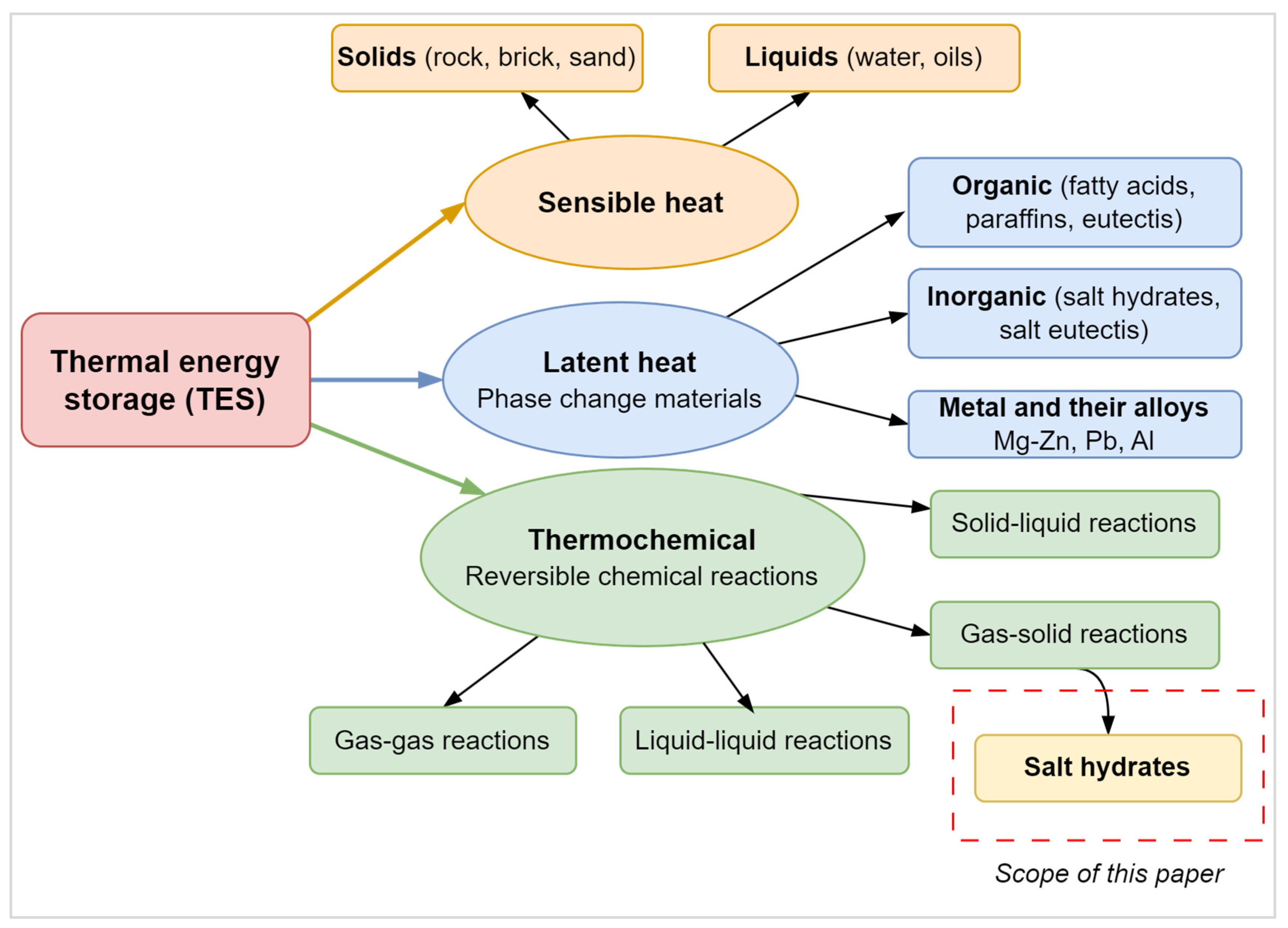
Thermal Energy Storage Technologies
2. An Overview of TCES
2.1. Salt Hydrates as PCMs
2.2. Sorption-Based TCES System
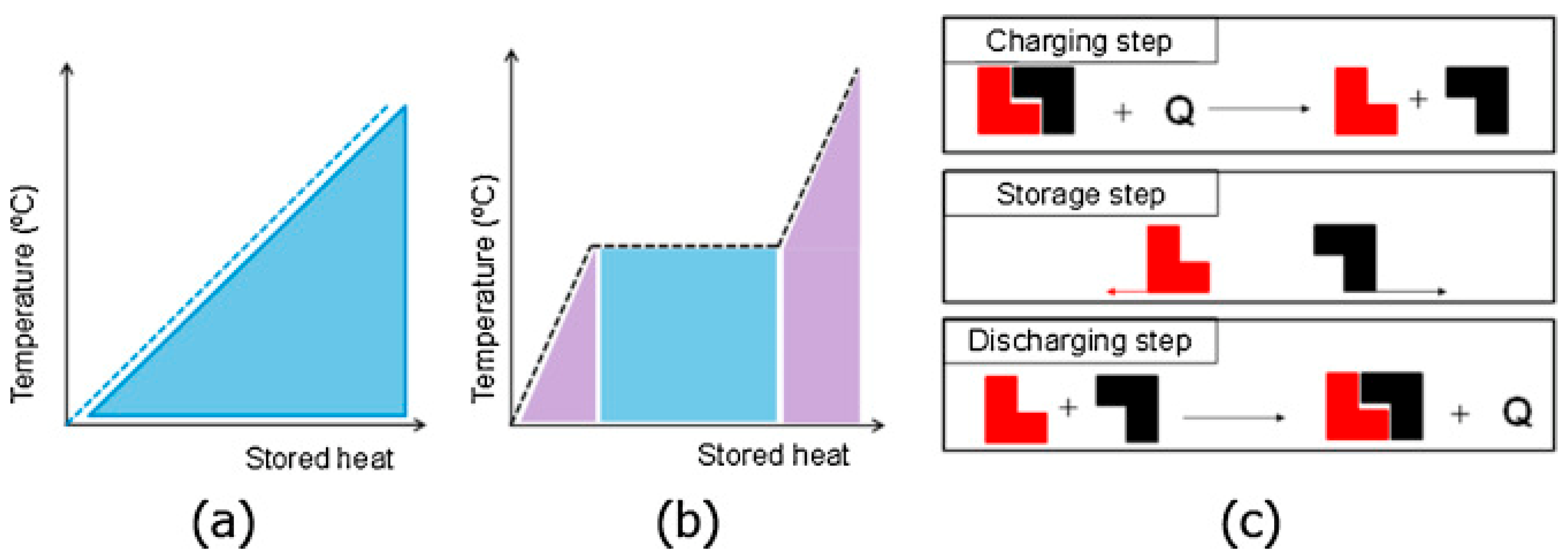
2.2.1. The Differences Between LHS and TCES Systems
2.2.2. Hydration and Dehydration
2.3. Advantages of Sorption-Based TCES Systems
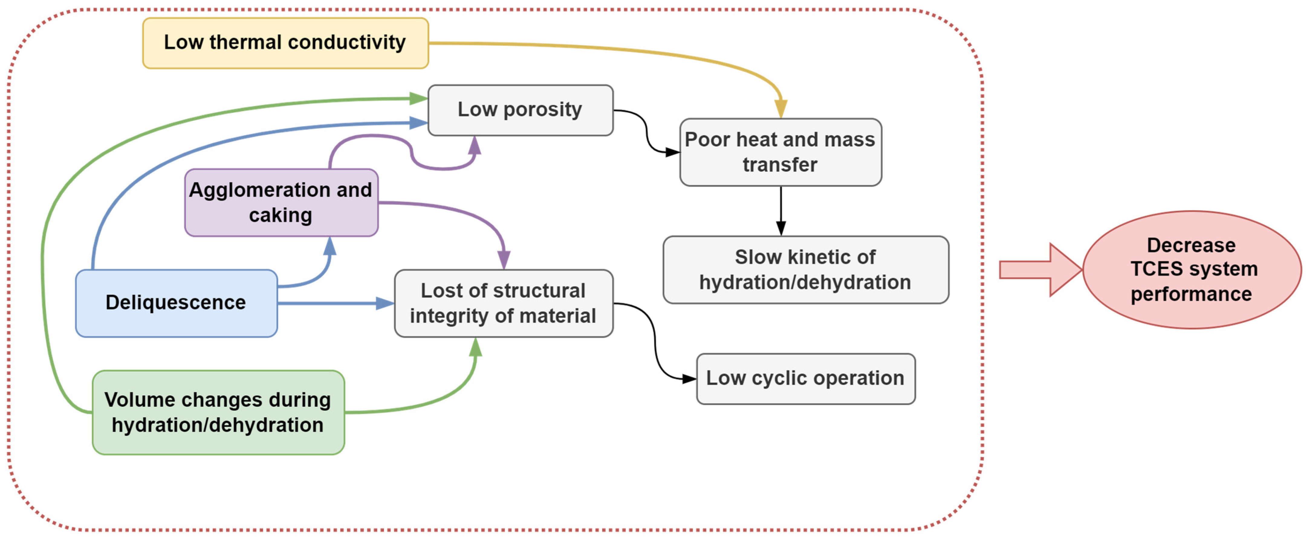
2.4. Barriers and Limitations of Sorption-Based TCES Systems
3. Salts Used in Water Vapor Sorption-Based TCES
3.1. Selection of TCES Material
3.2. Salt Hydrates Used in Sorption-Based TCES Systems
4. Materials Enhancement Strategies
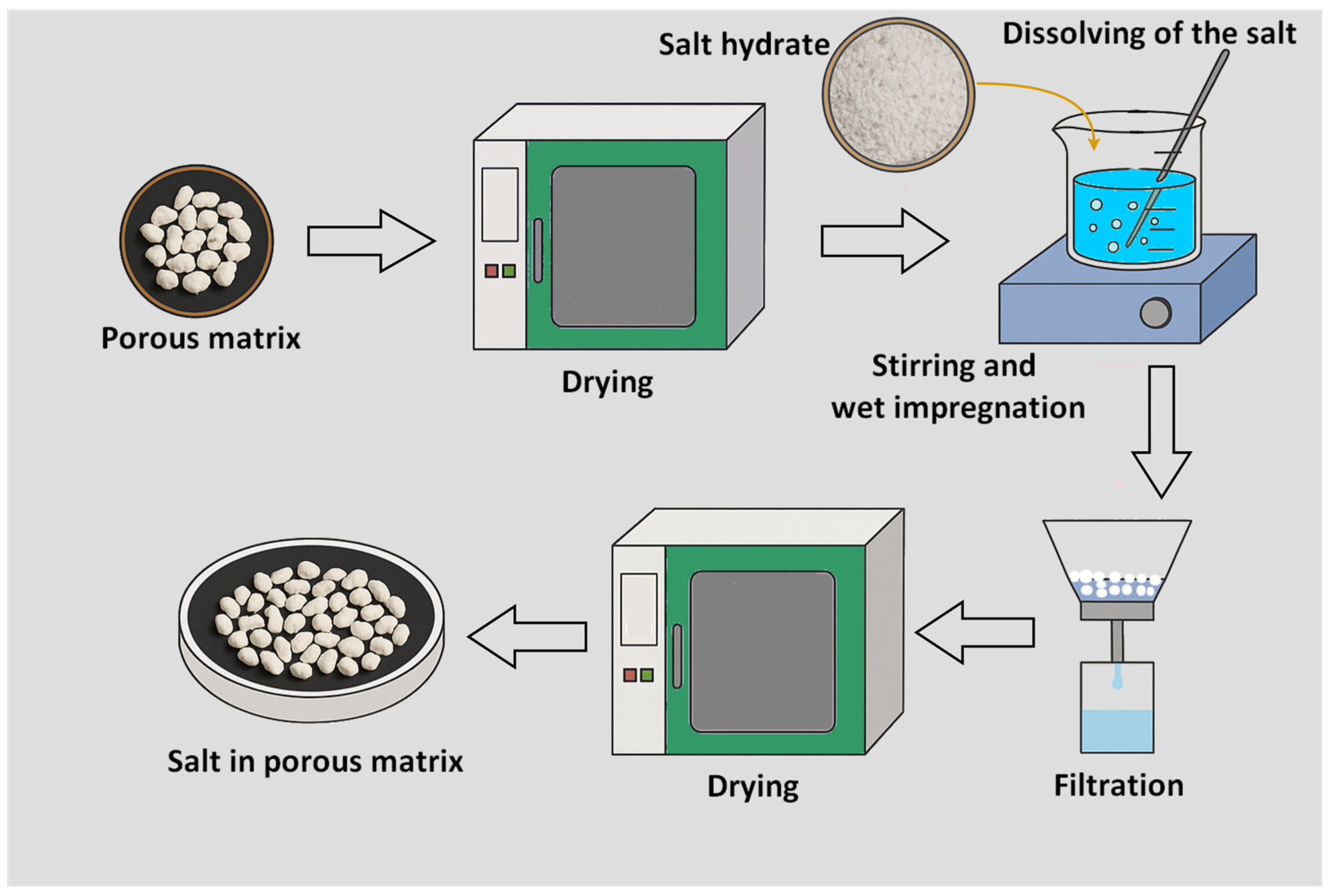
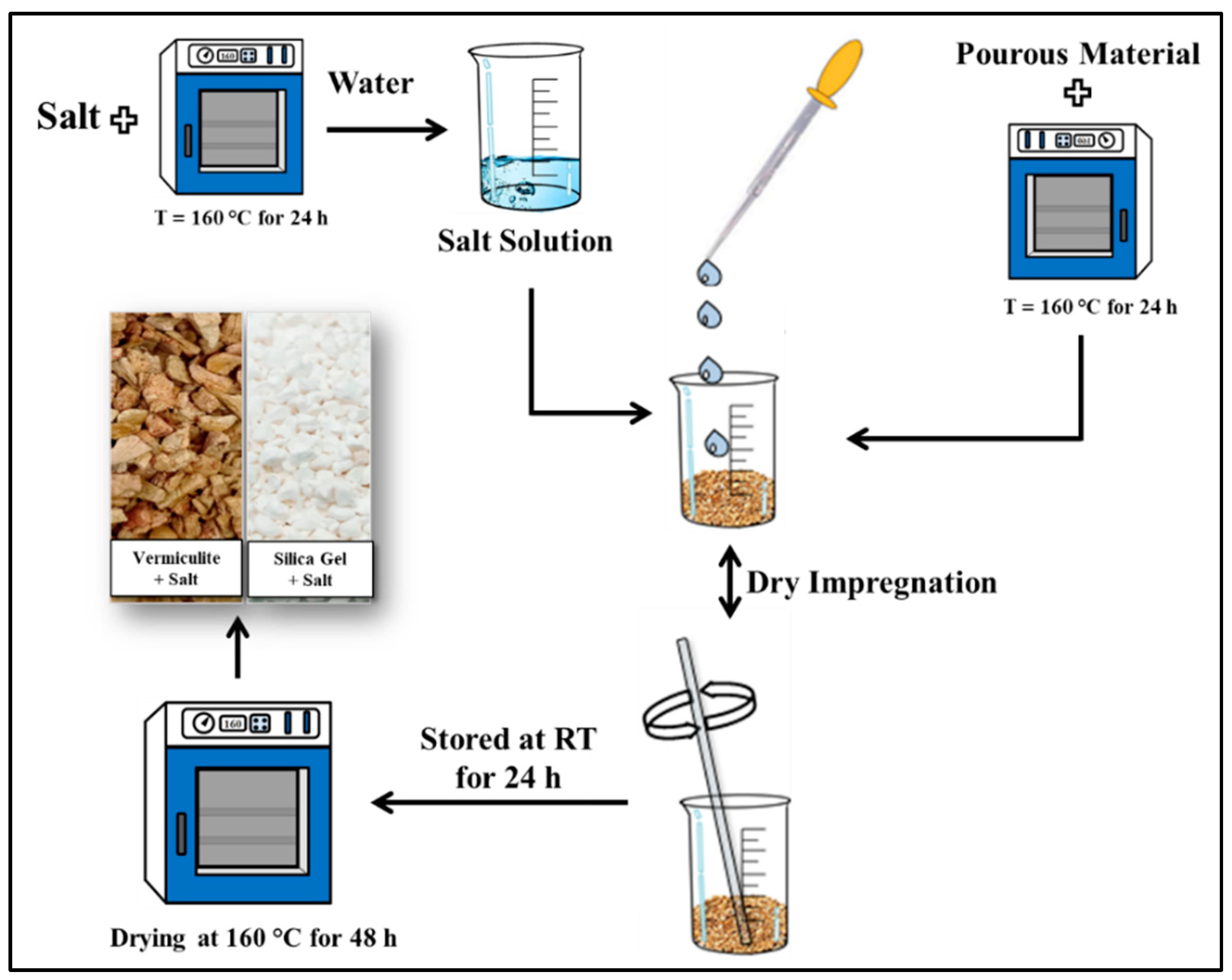
4.1. Salt in Porous Matrix Composite
4.2. Mixed Salts Composites
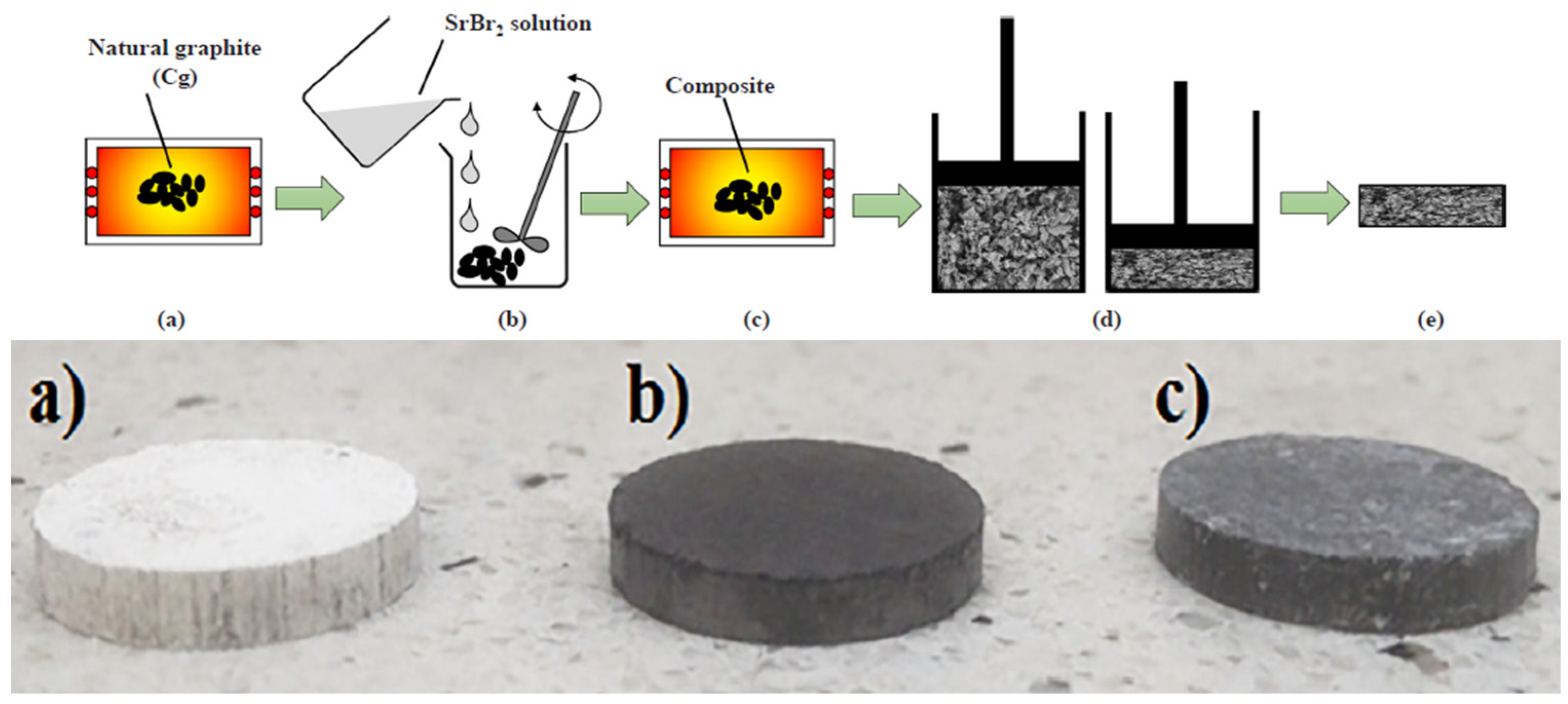
4.3. Consolidated Composites
5. Overview of TCES Concepts
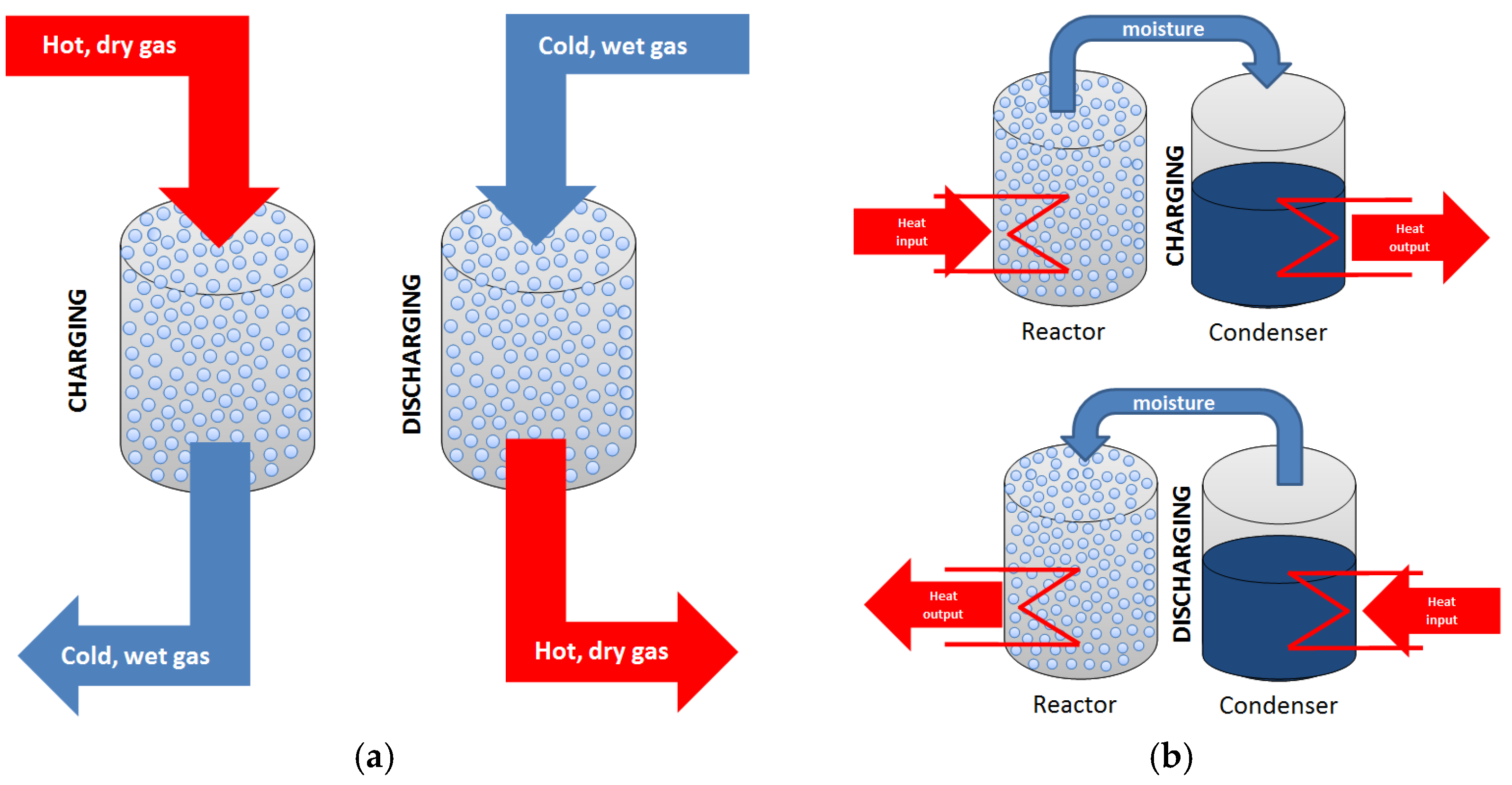
5.1. TCES System Configuration
5.2. Reactor Design in TCES System
- Fixed bed reactors (packed beds) involve a stationary arrangement of solid particles through which the reactive gas flows. These systems are relatively simple in design and operation, but suffer from limited heat and mass transfer, especially in larger-scale units. When efficient thermal exchange is critical, this limitation significantly constrains their applicability [264].
- Moving bed reactors allow for periodic or continuous removal of the solid phase. While the flow characteristics of the gas phase resemble those in fixed beds, the capacity to exchange or regenerate solids introduces operational flexibility. This is particularly beneficial in processes requiring cyclic material replacement or thermal regeneration.
- Fluidized bed reactors utilize fine solid particles suspended by an upward gas stream. When the gas velocity exceeds the minimum fluidization threshold but remains below the entrainment limit, the solid phase achieves a dynamic, fluid-like state. This configuration offers superior heat and mass transfer performance, uniform temperature distribution, and enhanced reaction kinetics, making it particularly advantageous for large-scale or highly exothermic/endothermic processes.
5.3. Research and Demonstration Projects
- “Compact chemical seasonal storage of solar heat”—ECN and Eindhoven University of Technology, The Netherlands;
- “Evaluation of thermo-chemical accumulator (TCA)”—SERC, Dalarna University, Sweden;
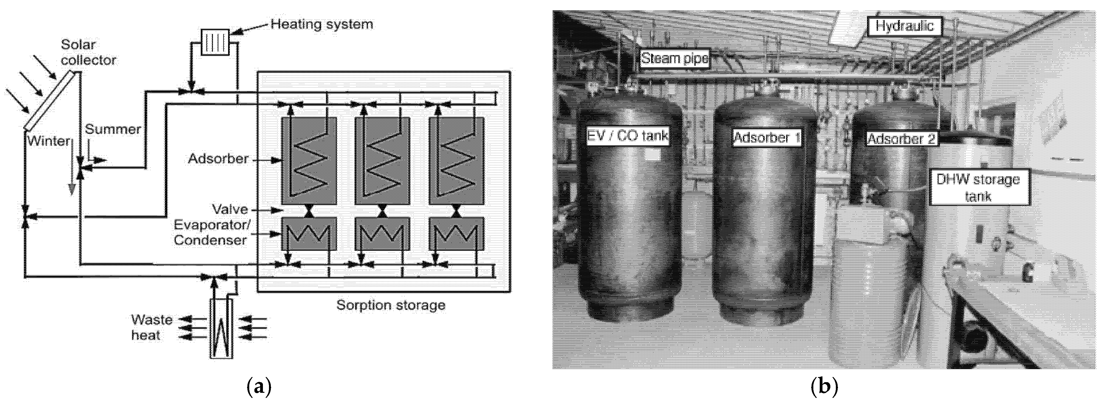
- “Sorption storage”—SPF Institute for Solar Technology, Switzerland;
- “Modestore (Modular high energy density heat storage)”—AEE INTEC, Austria;
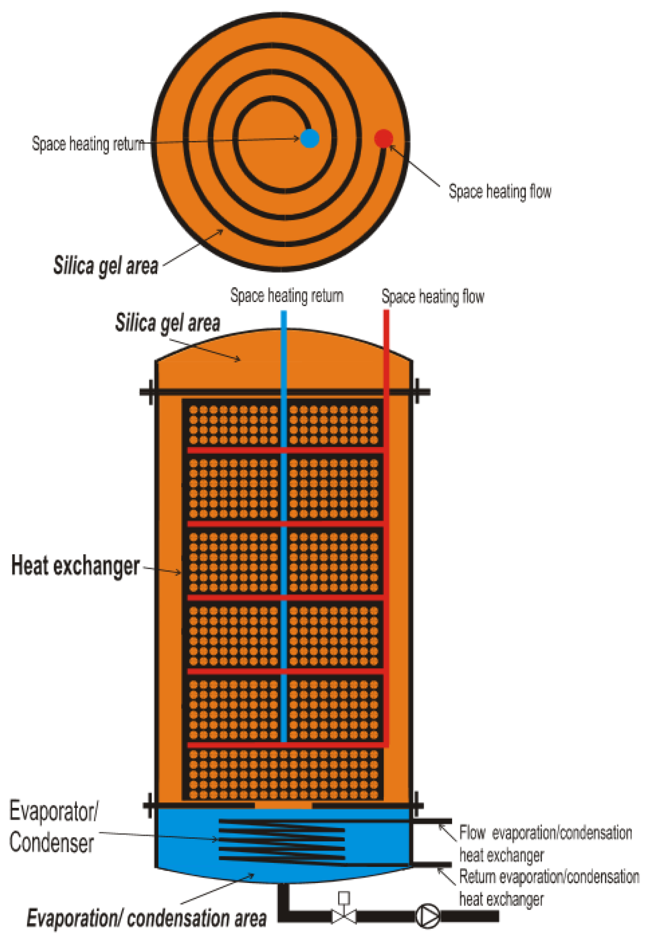
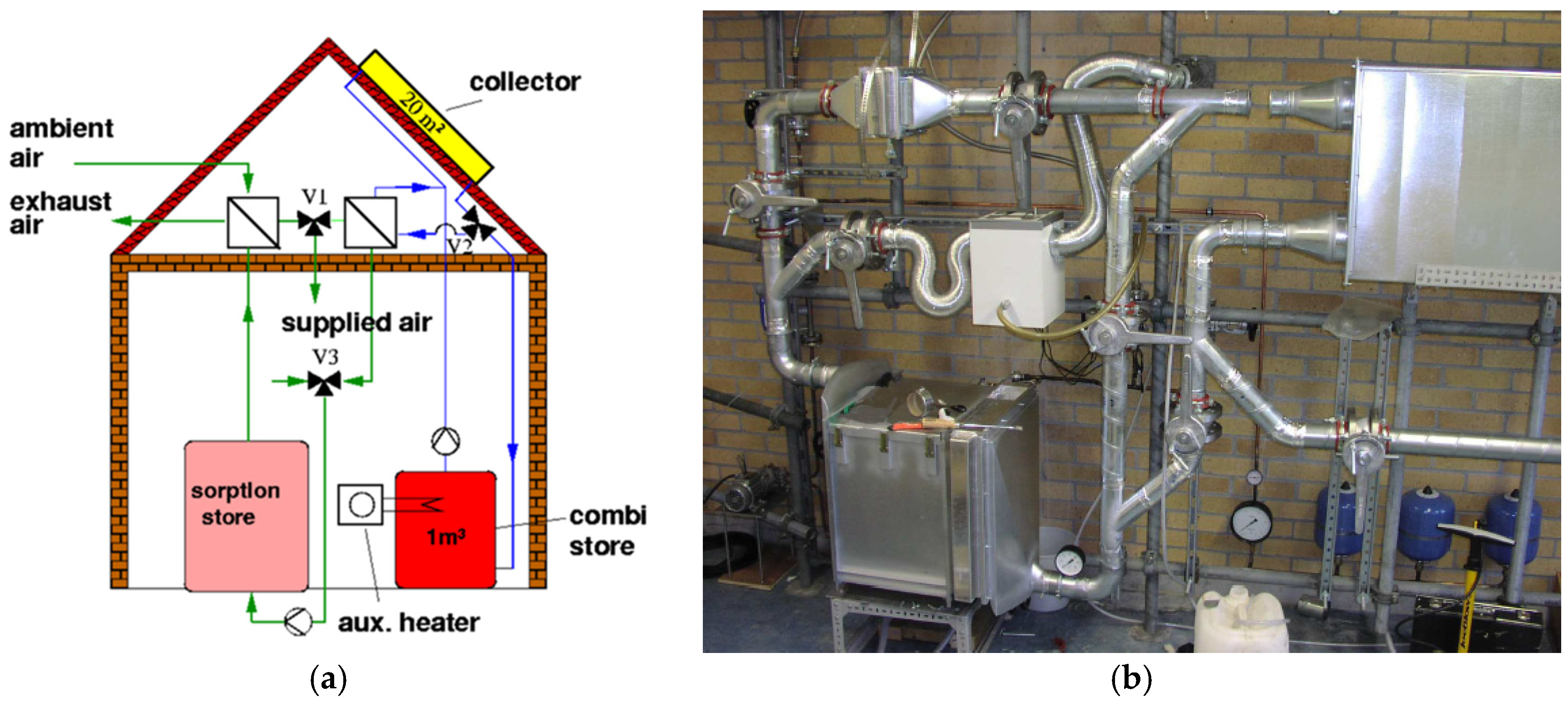
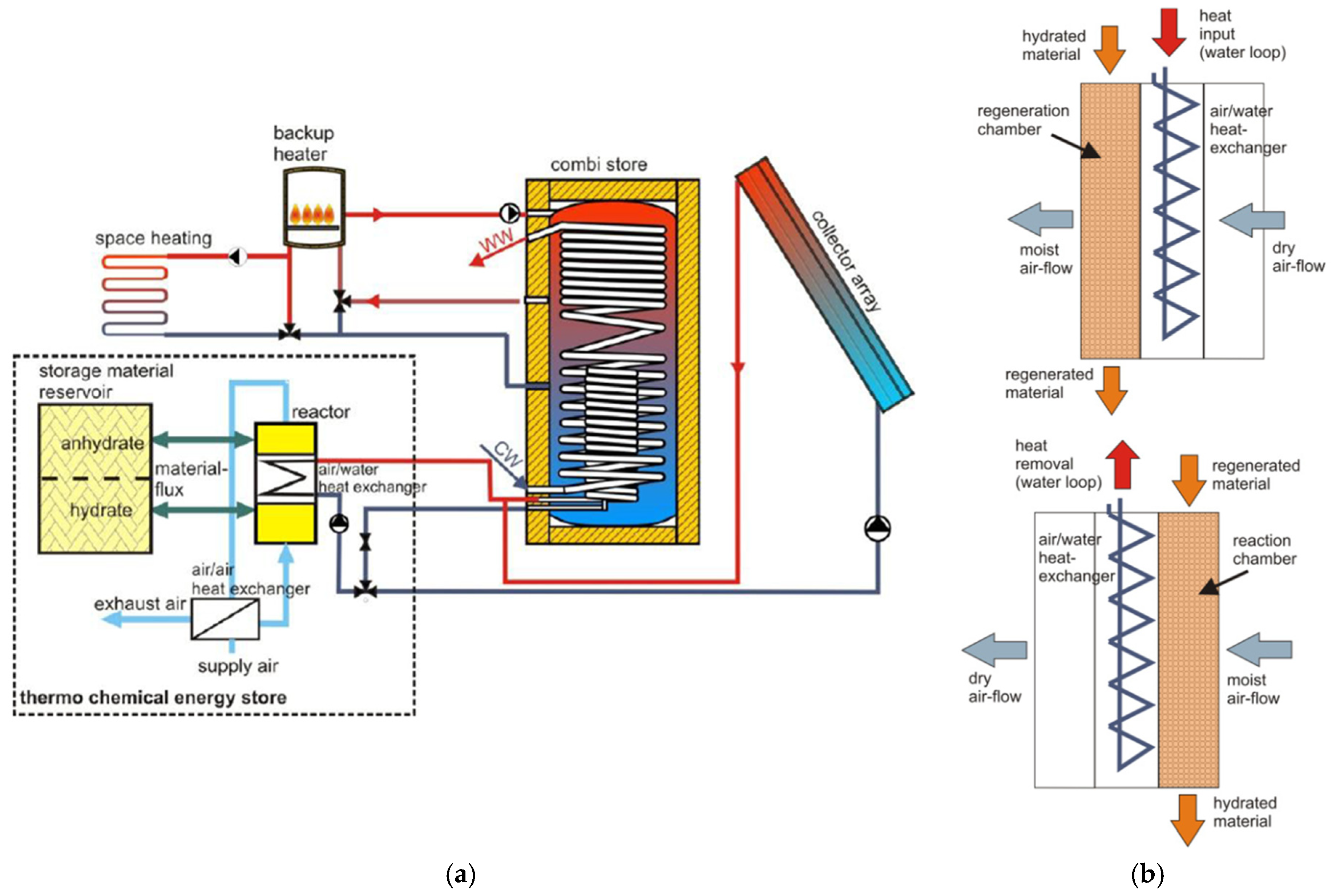
- “Monosorp”—ITW, University of Stuttgart, Germany;
- “Closed NaOH absorption storage”—EMPA, Switzerland.
6. Future Perspectives
- Improving material stability and performance: further research is needed to address issues such as deliquescence, agglomeration, and caking in salt hydrates, possibly through the development of more robust composite structures with optimized porous matrices and binders that can better maintain structural integrity and prevent salt leakage during cycling. Long-term testing to assess material degradation and thermal stability, as well as operational efficiency under real-world conditions, should be further investigated.
- Enhancing heat and mass transfer: future efforts should focus on improving the thermal conductivity and slow kinetics of salt hydrates. This could include exploring novel matrix materials (such as advanced carbon-based structures for improved thermal conductivity), optimizing the design and properties of composite materials, and investigating methods to improve mass transfer within the storage system.
- Optimizing material combinations: for porous composites, the influence of matrix type and pore size on thermochemical behavior should be further studied. Continued research into mixed salt systems, particularly binary combinations, is crucial to discover and optimize synergistic effects that can lead to improved energy storage density, faster reaction kinetics, and enhanced long-term stability under a wider range of operating conditions. Identifying optimal salt ratios and compatible pairings will be key. Ultimately, no single material is universally optimal, and choices must be adjusted to meet specific system requirements.
- Advancing TCES to real-world integration: large-scale cyclic testing of promising composites is needed to identify potential operational challenges. Economic considerations must guide material selection; while porous carbons and MOFs show excellent performance, their high cost limits practical use. Instead, attention should shift to natural, modified materials such as vermiculite and biochar. Similarly, research should aim to improve low-cost, abundant salts such as MgCl2, MgSO4, K2CO3, and CaCl2. High material costs remain a major obstacle to the large-scale deployment of TCES, so cost-effectiveness is essential. Binary salt systems are particularly promising because they allow the tailoring of properties using inexpensive components and porous supports. Moreover, comprehensive techno-economic analyses should be undertaken to assess cost-effectiveness and identify the main cost drivers.
- The reactor design: future research should focus on finding the optimal balance between bed thickness, packing density, and airflow resistance, particularly in fixed-bed reactors. To achieve this, future work should explore multi-layer reactor structures, the incorporation of fins, and the use of composite materials with improved thermal conductivity. For moving-bed reactors, ensuring good flowability and uniformity of storage materials is critical to avoid clogging and reduce maintenance costs. Moving bed reactors, due to their structural complexity and abrasion issues, require further research into durable materials and robust system designs.
- Improving the operation of the system: optimization should focus on adapting reactor configurations to operating conditions, improving mass transfer in open systems through modular bed design, and improving heat transfer in closed systems through advanced heat exchanger integration. Well-developed control methods for air temperature, humidity, and flow rate are crucial to ensure consistent system performance and efficiency, especially in open-cycle configurations. In addition, more emphasis should be placed on research into long-term operational performance, environmental robustness, and compatibility with larger energy systems (e.g., district heating, CSP).
7. Conclusions
- Salt hydrates offer high energy densities and long-term stability.
- Composite materials improve thermal and mechanical performance.
- Mixed salts exhibit synergistic effects, enhancing kinetics and water uptake.
- Consolidated forms improve structural integrity but require careful design to avoid mass transfer issues.
- Promising reactor designs and test rigs exist, but further optimization and standardization are needed for scale-up.
Author Contributions
Funding
Data Availability Statement
Acknowledgments
Conflicts of Interest
Abbreviations
| AC | activated carbon |
| AIPOs | aluminophosphates |
| CA | aoral aggregate |
| CAGR | compound annual growth rate |
| CMC | carboxymethyl cellulose |
| CN | calcium nitrate |
| CMS | Commercial mesoporous silica |
| CNT | carbon nano–tubes |
| COP | coefficient of performance |
| CSP | concentrated solar power |
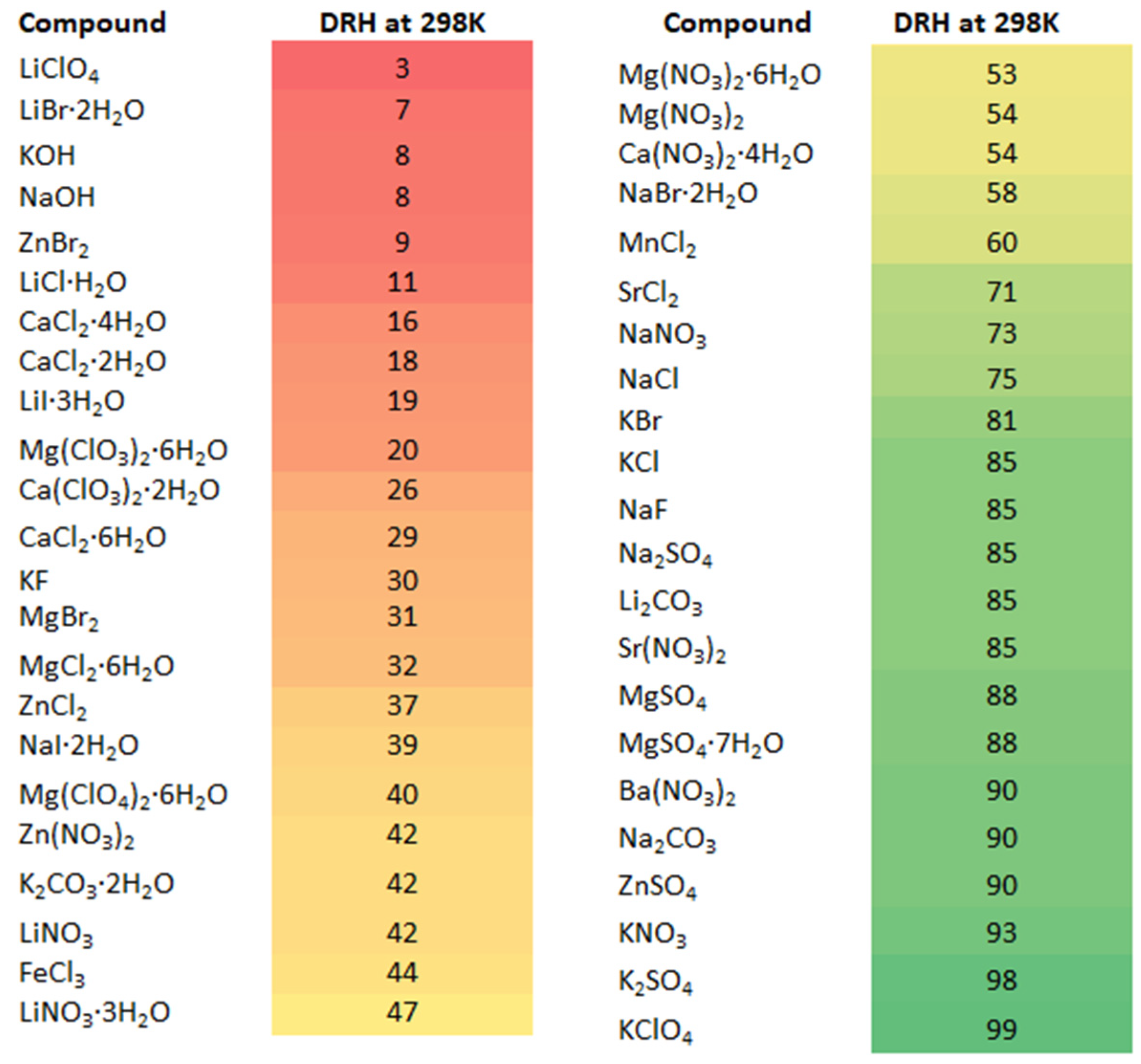
| DRH | deliquescence relative humidity |
| EG | expanded graphite |
| ENG–TSA | expanded natural graphite treated with sulfuric acid |
| EU | European Union |
| EV | expanded vermiculite |
| GHG | greenhouse gases |
| GO | graphene oxide aero–gel |
| HAP | hydroxyapatite |
| HPS | highly porous silica |
| HTF | heat transfer fluid |
| LC | lithium carbonate |
| LCA | life cycle assessment |
| LCOE | levelized cost of energy |
| LHS | latent heat storage |
| LN | lithium nitrate |
| MCF | mesostructured cellular foam |
| MOFs | metal organic frameworks |
| PC | potassium carbonate |
| PCMs | phase change materials |
| PEG | Polyethylene glycol |
| PN | potassium nitrate |
| PV | photovoltaics |
| PVA | polyvinyl alcohol |
| PVP | polyvinylpyrrolidone |
| R&D | research and development |
| RED | Renewable Energy Directive |
| RES | renewable energy sources |
| RH | relative humidity |
| RMSD | root mean square deviation |
| RMSPE | root mean square percentage error |
| RTEG | room temperature expanded graphite |
| SAPOs | silico–aluminophosphates |
| SC | sodium carbonate |
| SHS | sensible heat storage |
| SN | sodium nitrate |
| SPMC | salt in a porous matrix composite |
| TCES | thermochemical energy storage |
| TCM | thermochemical material |
| TEOS | tetraethyl orthosilicate |
| TES | thermal energy storage |
| TG/TGA | thermogravimetric analysis |
| TG–DSC | thermogravimetric and differential scanning calorimetry |
References
- Energy Statistics—An Overview (Eurostat Official Website of the EU). Available online: https://ec.europa.eu/eurostat/statistics-explained/index.php?title=Energy_statistics_-_an_overview (accessed on 13 February 2025).
- IEA Web Page—Emissions. Available online: https://www.iea.org/regions/europe (accessed on 13 February 2025).
- Martins, F.; Felgueiras, C.; Smitkova, M.; Caetano, N. Analysis of Fossil Fuel Energy Consumption and Environmental Impacts in European Countries. Energies 2019, 12, 964. [Google Scholar] [CrossRef]
- European Environment Agency—Share of Energy Consumption from Renewable Sources in Europe. Available online: https://www.eea.europa.eu/en/analysis/indicators/share-of-energy-consumption-from (accessed on 13 February 2025).
- Paraschiv, S. Analysis of the Variability of Low-Carbon Energy Sources, Nuclear Technology and Renewable Energy Sources, in Meeting Electricity Demand. Energy Rep. 2023, 9, 276–283. [Google Scholar] [CrossRef]
- Steinmann, W.-D. Overview of the Section on Mechanical Energy Storage. In Encyclopedia of Energy Storage; Cabeza, L.F., Ed.; Elsevier: Oxford, UK, 2022; pp. 1–4. ISBN 978-0-12-819730-1. [Google Scholar]
- Detka, K.; Górecki, K. Selected Technologies of Electrochemical Energy Storage—A Review. Energies 2023, 16, 5034. [Google Scholar] [CrossRef]
- Tawalbeh, M.; Khan, H.A.; Al-Othman, A.; Almomani, F.; Ajith, S. A Comprehensive Review on the Recent Advances in Materials for Thermal Energy Storage Applications. Int. J. Thermofluids 2023, 18, 100326. [Google Scholar] [CrossRef]
- International Renewable Energy Agency—Medium- and High-Temperature Thermal Energy Storage. Available online: https://www.irena.org/Innovation-landscape-for-smart-electrification/Power-to-heat-and-cooling/7-Medium-and-high-temperature-thermal-energy-storage (accessed on 19 May 2025).
- Sarbu, I.; Sebarchievici, C. A Comprehensive Review of Thermal Energy Storage. Sustainability 2018, 10, 191. [Google Scholar] [CrossRef]
- Furbo, S. 2—Using Water for Heat Storage in Thermal Energy Storage (TES) Systems. In Advances in Thermal Energy Storage Systems; Cabeza, L.F., Ed.; Woodhead Publishing Series in Energy; Woodhead Publishing: Cambridge, UK, 2015; pp. 31–47. ISBN 978-1-78242-088-0. [Google Scholar]
- Yuvaaraj, J.S.; Deepakkumar, R. Advancement in Experimental and Computational Approach for Thermal Performance Investigation of Single-Tank Packed Bed Thermal Energy Storage System. J. Braz. Soc. Mech. Sci. Eng. 2024, 46, 433. [Google Scholar] [CrossRef]
- Zuwała, J. Determination of the optimum turbine power rating and a hot water storage tank volume for condensing turbine based CHP plant with thermal storage. Polityka Energ.—Energy Policy J. 2005, 8, 585–601. [Google Scholar]
- Sharma, A.; Tyagi, V.V.; Chen, C.R.; Buddhi, D. Review on Thermal Energy Storage with Phase Change Materials and Applications. Renew. Sustain. Energy Rev. 2009, 13, 318–345. [Google Scholar] [CrossRef]
- Gil, A.; Medrano, M.; Martorell, I.; Lázaro, A.; Dolado, P.; Zalba, B.; Cabeza, L.F. State of the Art on High Temperature Thermal Energy Storage for Power Generation. Part 1—Concepts, Materials and Modellization. Renew. Sustain. Energy Rev. 2010, 14, 31–55. [Google Scholar] [CrossRef]
- Kenisarin, M.M. High-Temperature Phase Change Materials for Thermal Energy Storage. Renew. Sustain. Energy Rev. 2010, 14, 955–970. [Google Scholar] [CrossRef]
- Kenisarin, M.; Mahkamov, K. Solar Energy Storage Using Phase Change Materials. Renew. Sustain. Energy Rev. 2007, 9, 1913–1965. [Google Scholar] [CrossRef]
- Kenisarin, M.; Mahkamov, K. Salt Hydrates as Latent Heat Storage Materials: Thermophysical Properties and Costs. Sol. Energy Mater. Sol. Cells 2016, 145, 255–286. [Google Scholar] [CrossRef]
- Zhang, H.L.; Baeyens, J.; Degrève, J.; Pitié, F. Latent Heat Storage with Phase Change Materials (PCMs). J. Technol. Innov. Renew. Energy 2013, 2, 340–351. [Google Scholar] [CrossRef]
- Al-Abidi, A.A.; Bin Mat, S.; Sopian, K.; Sulaiman, M.Y.; Lim, C.H.; Th, A. Review of Thermal Energy Storage for Air Conditioning Systems. Renew. Sustain. Energy Rev. 2012, 16, 5802–5819. [Google Scholar] [CrossRef]
- Martínez, F.R.; Borri, E.; Mani Kala, S.; Ushak, S.; Cabeza, L.F. Phase Change Materials for Thermal Energy Storage in Industrial Applications. Heliyon 2025, 11, e41025. [Google Scholar] [CrossRef]
- Pereira da Cunha, J.; Eames, P. Thermal Energy Storage for Low and Medium Temperature Applications Using Phase Change Materials—A Review. Appl. Energy 2016, 177, 227–238. [Google Scholar] [CrossRef]
- Negi, A.; Ranakoti, L.; Verma, R.P.; Kumar, V.; Bhandari, P.; Khargotra, R.; Singh, T. Enhancing Solar Still Productivity with Organic Phase Change Materials: A Literature Review. Energy Convers. Manag. X 2025, 26, 100984. [Google Scholar] [CrossRef]
- Yang, H.; Zou, Y.; Cui, H. Advancements and Challenges in Enhancing Salt Hydrate Phase Change Materials for Building Energy Storage: Optimization Methodologies and Mechanisms. Natl. Sci. Open 2024, 3, 20230056. [Google Scholar] [CrossRef]
- Jayathunga, D.S.; Karunathilake, H.P.; Narayana, M.; Witharana, S. Phase Change Material (PCM) Candidates for Latent Heat Thermal Energy Storage (LHTES) in Concentrated Solar Power (CSP) Based Thermal Applications—A Review. Renew. Sustain. Energy Rev. 2024, 189, 113904. [Google Scholar] [CrossRef]
- Grabski, A.; Lasek, J.; Zuwała, J. Concept and modeling of the storage system using a metallurgical furnace. Polityka Energ.—Energy Policy J. 2017, 20, 117–128. [Google Scholar]
- Venkateswarlu, K.; Ramakrishna, K. Recent Advances in Phase Change Materials for Thermal Energy Storage-a Review. J. Braz. Soc. Mech. Sci. Eng. 2021, 44, 6. [Google Scholar] [CrossRef]
- Chandel, S.S.; Agarwal, T. Review of Current State of Research on Energy Storage, Toxicity, Health Hazards and Commercialization of Phase Changing Materials. Renew. Sustain. Energy Rev. 2017, 67, 581–596. [Google Scholar] [CrossRef]
- Vignarooban, K.; Xu, X.; Arvay, A.; Hsu, K.; Kannan, A.M. Heat Transfer Fluids for Concentrating Solar Power Systems—A Review. Appl. Energy 2015, 146, 383–396. [Google Scholar] [CrossRef]
- Naveenkumar, R.; Ravichandran, M.; Mohanavel, V.; Karthick, A.; Aswin, L.S.R.L.; Priyanka, S.S.H.; Kumar, S.K.; Kumar, S.P. Review on Phase Change Materials for Solar Energy Storage Applications. Environ. Sci. Pollut. Res. 2022, 29, 9491–9532. [Google Scholar] [CrossRef]
- Li, Z.; Lu, Y.; Huang, R.; Chang, J.; Yu, X.; Jiang, R.; Yu, X.; Roskilly, A.P. Applications and Technological Challenges for Heat Recovery, Storage and Utilisation with Latent Thermal Energy Storage. Appl. Energy 2021, 283, 116277. [Google Scholar] [CrossRef]
- Farkas, D.; Birchenall, C.E. New Eutectic Alloys and Their Heats of Transformation. Metall. Trans. A 1985, 16, 323–328. [Google Scholar] [CrossRef]
- Shamberger, P.J.; Bruno, N.M. Review of Metallic Phase Change Materials for High Heat Flux Transient Thermal Management Applications. Appl. Energy 2020, 258, 113955. [Google Scholar] [CrossRef]
- Mofijur, M.; Mahlia, T.M.I.; Silitonga, A.S.; Ong, H.C.; Silakhori, M.; Hasan, M.H.; Putra, N.; Rahman, S.M.A. Phase Change Materials (PCM) for Solar Energy Usages and Storage: An Overview. Energies 2019, 12, 3167. [Google Scholar] [CrossRef]
- Al-Shannaq, R.; Kurdi, J.; Al-Muhtaseb, S.; Dickinson, M.; Farid, M. Supercooling Elimination of Phase Change Materials (PCMs) Microcapsules. Energy 2015, 87, 654–662. [Google Scholar] [CrossRef]
- Kumar, N.; Hirschey, J.; LaClair, T.J.; Gluesenkamp, K.R.; Graham, S. Review of Stability and Thermal Conductivity Enhancements for Salt Hydrates. J. Energy Storage 2019, 24, 100794. [Google Scholar] [CrossRef]
- Banaszek, J.; Domañski, R.; Rebow, M.; El-Sagier, F. Experimental Study of Solid–Liquid Phase Change in a Spiral Thermal Energy Storage Unit. Appl. Therm. Eng. 1999, 19, 1253–1277. [Google Scholar] [CrossRef]
- Medrano, M.; Yilmaz, M.O.; Nogués, M.; Martorell, I.; Roca, J.; Cabeza, L.F. Experimental Evaluation of Commercial Heat Exchangers for Use as PCM Thermal Storage Systems. Appl. Energy 2009, 86, 2047–2055. [Google Scholar] [CrossRef]
- Jian-you, L. Numerical and Experimental Investigation for Heat Transfer in Triplex Concentric Tube with Phase Change Material for Thermal Energy Storage. Sol. Energy 2008, 82, 977–985. [Google Scholar] [CrossRef]
- Yang, K.; Zhu, N.; Li, Y.; Du, N. Effect of Parameters on the Melting Performance of Triplex Tube Heat Exchanger Incorporating Phase Change Material. Renew. Energy 2021, 174, 359–371. [Google Scholar] [CrossRef]
- Al-Mudhafar, A.H.N.; Nowakowski, A.F.; Nicolleau, F.C.G.A. Thermal Performance Enhancement of Energy Storage Systems via Phase Change Materials Utilising an Innovative Webbed Tube Heat Exchanger. Energy Procedia 2018, 151, 57–61. [Google Scholar] [CrossRef]
- Agyenim, F.; Eames, P.; Smyth, M. A Comparison of Heat Transfer Enhancement in a Medium Temperature Thermal Energy Storage Heat Exchanger Using Fins. Sol. Energy 2009, 83, 1509–1520. [Google Scholar] [CrossRef]
- Fukai, J.; Hamada, Y.; Morozumi, Y.; Miyatake, O. Effect of Carbon-Fiber Brushes on Conductive Heat Transfer in Phase Change Materials. Int. J. Heat Mass Transf. 2002, 45, 4781–4792. [Google Scholar] [CrossRef]
- Mahdi, J.M.; Nsofor, E.C. Solidification of a PCM with Nanoparticles in Triplex-Tube Thermal Energy Storage System. Appl. Therm. Eng. 2016, 108, 596–604. [Google Scholar] [CrossRef]
- Chieruzzi, M.; Cerritelli, G.F.; Miliozzi, A.; Kenny, J.M. Effect of Nanoparticles on Heat Capacity of Nanofluids Based on Molten Salts as PCM for Thermal Energy Storage. Nanoscale Res. Lett. 2013, 8, 448. [Google Scholar] [CrossRef]
- Zhang, X.; Wen, R.; Huang, Z.; Tang, C.; Huang, Y.; Liu, Y.; Fang, M.; Wu, X.; Min, X.; Xu, Y. Enhancement of Thermal Conductivity by the Introduction of Carbon Nanotubes as a Filler in Paraffin/Expanded Perlite Form-Stable Phase-Change Materials. Energy Build. 2017, 149, 463–470. [Google Scholar] [CrossRef]
- Motahar, S.; Alemrajabi, A.A.; Khodabandeh, R. Experimental Study on Solidification Process of a Phase Change Material Containing TiO2 Nanoparticles for Thermal Energy Storage. Energy Convers. Manag. 2017, 138, 162–170. [Google Scholar] [CrossRef]
- Mettawee, E.-B.S.; Assassa, G.M.R. Thermal Conductivity Enhancement in a Latent Heat Storage System. Sol. Energy 2007, 81, 839–845. [Google Scholar] [CrossRef]
- Oya, T.; Nomura, T.; Okinaka, N.; Akiyama, T. Phase Change Composite Based on Porous Nickel and Erythritol. Appl. Therm. Eng. 2012, 40, 373–377. [Google Scholar] [CrossRef]
- Li, M.; Guo, Q.; Nutt, S. Carbon Nanotube/Paraffin/Montmorillonite Composite Phase Change Material for Thermal Energy Storage. Sol. Energy 2017, 146, 1–7. [Google Scholar] [CrossRef]
- Zahir, H.; Mohamed, S.A.; Saidur, R.; Al-Sulaiman, F.A. Supercooling of Phase-Change Materials and the Techniques Used to Mitigate the Phenomenon. Appl. Energy 2019, 240, 793–817. [Google Scholar] [CrossRef]
- Thakkar, J.; Annavajjala, S.B.; Kosny, J.; Sobkowicz, M.J. Stabilizing a Low Temperature Phase Change Material Based on Glaubers Salt. J. Energy Storage 2024, 91, 111936. [Google Scholar] [CrossRef]
- Alva, G.; Liu, L.; Huang, X.; Fang, G. Thermal Energy Storage Materials and Systems for Solar Energy Applications. Renew. Sustain. Energy Rev. 2017, 68, 693–706. [Google Scholar] [CrossRef]
- Ong, T.-C.; Sarvghad, M.; Bell, S.; Will, G.; Steinberg, T.A.; Yin, Y.; Andersson, G.; Lewis, D. Review on the Challenges of Salt Phase Change Materials for Energy Storage in Concentrated Solar Power Facilities. Appl. Therm. Eng. 2024, 238, 122034. [Google Scholar] [CrossRef]
- Crespo, A.; Barreneche, C.; Ibarra, M.; Platzer, W. Latent Thermal Energy Storage for Solar Process Heat Applications at Medium-High Temperatures—A Review. Sol. Energy 2019, 192, 3–34. [Google Scholar] [CrossRef]
- Thambidurai, M.; Panchabikesan, K.; N, K.M.; Ramalingam, V. Review on Phase Change Material Based Free Cooling of Buildings—The Way toward Sustainability. J. Energy Storage 2015, 4, 74–88. [Google Scholar] [CrossRef]
- Waqas, A.; Ud Din, Z. Phase Change Material (PCM) Storage for Free Cooling of Buildings—A Review. Renew. Sustain. Energy Rev. 2013, 18, 607–625. [Google Scholar] [CrossRef]
- Akeiber, H.; Nejat, P.; Majid, M.Z.A.; Wahid, M.A.; Jomehzadeh, F.; Zeynali Famileh, I.; Calautit, J.K.; Hughes, B.R.; Zaki, S.A. A Review on Phase Change Material (PCM) for Sustainable Passive Cooling in Building Envelopes. Renew. Sustain. Energy Rev. 2016, 60, 1470–1497. [Google Scholar] [CrossRef]
- Xu, B.; Li, P.; Chan, C. Application of Phase Change Materials for Thermal Energy Storage in Concentrated Solar Thermal Power Plants: A Review to Recent Developments. Appl. Energy 2015, 160, 286–307. [Google Scholar] [CrossRef]
- Mohamed, S.A.; Al-Sulaiman, F.A.; Ibrahim, N.I.; Zahir, H.; Al-Ahmed, A.; Saidur, R.; Yılbaş, B.S.; Sahin, A.Z. A Review on Current Status and Challenges of Inorganic Phase Change Materials for Thermal Energy Storage Systems. Renew. Sustain. Energy Rev. 2017, 70, 1072–1089. [Google Scholar] [CrossRef]
- Al-Yasiri, Q.; Szabó, M. Selection of Phase Change Material Suitable for Building Heating Applications Based on Qualitative Decision Matrix. Energy Convers. Manag. X 2021, 12, 100150. [Google Scholar] [CrossRef]
- El-Raheim, D.A.; Mohamed, A.; Abou-Ziyan, H.; Fatouh, M. The Essential Properties Governing the Appropriate Selection of Phase Change Materials Integrated into Heavy Structure Buildings. Energy 2023, 266, 126515. [Google Scholar] [CrossRef]
- Mazur, N.; Blijlevens, M.A.R.; Ruliaman, R.; Fischer, H.; Donkers, P.; Meekes, H.; Vlieg, E.; Adan, O.; Huinink, H. Revisiting Salt Hydrate Selection for Domestic Heat Storage Applications. Renew. Energy 2023, 218, 119331. [Google Scholar] [CrossRef]
- Chatterjee, R.; Chaudhari, U.; Anand, S. How to Select Phase Change Materials for Tuning Condensation and Frosting? Adv. Funct. Mater. 2023, 33, 2206301. [Google Scholar] [CrossRef]
- Jurczyk, M.; Spietz, T.; Czardybon, A.; Dobras, S.; Ignasiak, K.; Bartela, Ł.; Uchman, W.; Ochmann, J. Review of Thermal Energy Storage Materials for Application in Large-Scale Integrated Energy Systems—Methodology for Matching Heat Storage Solutions for Given Applications. Energies 2024, 17, 3544. [Google Scholar] [CrossRef]
- Rao, R.V. Phase Change Material Selection for Energy Storage Units Using a Simple and Effective Decision-Making Method. Arch. Thermodyn. 2024, 45, 67–79. [Google Scholar] [CrossRef]
- Wei, G.; Wang, G.; Xu, C.; Ju, X.; Xing, L.; Du, X.; Yang, Y. Selection Principles and Thermophysical Properties of High Temperature Phase Change Materials for Thermal Energy Storage: A Review. Renew. Sustain. Energy Rev. 2018, 81, 1771–1786. [Google Scholar] [CrossRef]
- Kulish, V.; Aslfattahi, N.; Schmirler, M.; Sláma, P. New Library of Phase-Change Materials with Their Selection by the Rényi Entropy Method. Sci. Rep. 2023, 13, 10446. [Google Scholar] [CrossRef] [PubMed]
- Zeng, Y.; Zhou, T.; Wang, T.; Zhang, M.; Zhang, S.; Yang, H. Long-Duration Energy Storage: A Critical Enabler for Renewable Integration and Decarbonization. Energies 2025, 18, 466. [Google Scholar] [CrossRef]
- Salama, M.M.; Mohamed, S.A.; Attalla, M.; Shmroukh, A.N. Experimental Investigation on a Thermochemical Seasonal Sorption Energy Storage Battery Utilizing MgSO4-H2O. Environ. Sci. Pollut. Res. 2023, 30, 98502–98525. [Google Scholar] [CrossRef]
- Nguyen, M.H.; Zbair, M.; Dutournié, P.; Bennici, S. Thermochemical Sorption Heat Storage: Investigate the Heat Released from Activated Carbon Beads Used as Porous Host Matrix for MgSO4 Salt. J. Energy Storage 2023, 59, 106452. [Google Scholar] [CrossRef]
- Roger-Lund, S.; Darkwa, J.; Worall, M.; Calautit, J.; Boukhanouf, R. A Review of Thermochemical Energy Storage Systems for District Heating in the UK. Energies 2024, 17, 3389. [Google Scholar] [CrossRef]
- de Gracia, A.; Cabeza, L.F. Phase Change Materials and Thermal Energy Storage for Buildings. Energy Build. 2015, 103, 414–419. [Google Scholar] [CrossRef]
- Yan, T.; Wang, R.Z.; Li, T.X.; Wang, L.W.; Fred, I.T. A Review of Promising Candidate Reactions for Chemical Heat Storage. Renew. Sustain. Energy Rev. 2015, 43, 13–31. [Google Scholar] [CrossRef]
- Clark, R.-J.; Mehrabadi, A.; Farid, M. State of the Art on Salt Hydrate Thermochemical Energy Storage Systems for Use in Building Applications. J. Energy Storage 2020, 27, 101145. [Google Scholar] [CrossRef]
- Han, X.; Zeng, C.; Zhu, Z.; Sun, Y.; Zhao, X. Investigation of a Novel Thermochemical Reactor for Medium- and Low-Temperature Heating Applications in Buildings. Buildings 2024, 14, 3192. [Google Scholar] [CrossRef]
- Hayatina, I.; Auckaili, A.; Farid, M. Review on Salt Hydrate Thermochemical Heat Transformer. Energies 2023, 16, 4668. [Google Scholar] [CrossRef]
- Ortiz, C. Thermochemical Energy Storage Based on Carbonates: A Brief Overview. Energies 2021, 14, 4336. [Google Scholar] [CrossRef]
- Raganati, F.; Ammendola, P. Review of Carbonate-Based Systems for Thermochemical Energy Storage for Concentrating Solar Power Applications: State-of-the-Art and Outlook. Energy Fuels 2023, 37, 1777–1808. [Google Scholar] [CrossRef]
- Wu, S.; Zhou, C.; Doroodchi, E.; Nellore, R.; Moghtaderi, B. A Review on High-Temperature Thermochemical Energy Storage Based on Metal Oxides Redox Cycle. Energy Convers. Manag. 2018, 168, 421–453. [Google Scholar] [CrossRef]
- Calderón, A.; Barreneche, C.; Hernández-Valle, K.; Galindo, E.; Segarra, M.; Fernández, A.I. Where Is Thermal Energy Storage (TES) Research Going?—A Bibliometric Analysis. Sol. Energy 2020, 200, 37–50. [Google Scholar] [CrossRef]
- Clark, R.-J.; Gholamibozanjani, G.; Woods, J.; Kaur, S.; Odukomaiya, A.; Al-Hallaj, S.; Farid, M. Experimental Screening of Salt Hydrates for Thermochemical Energy Storage for Building Heating Application. J. Energy Storage 2022, 51, 104415. [Google Scholar] [CrossRef]
- N’Tsoukpoe, K.E.; Schmidt, T.; Rammelberg, H.U.; Watts, B.A.; Ruck, W.K.L. A Systematic Multi-Step Screening of Numerous Salt Hydrates for Low Temperature Thermochemical Energy Storage. Appl. Energy 2014, 124, 1–16. [Google Scholar] [CrossRef]
- Richter, M.; Habermann, E.-M.; Siebecke, E.; Linder, M. A Systematic Screening of Salt Hydrates as Materials for a Thermochemical Heat Transformer. Thermochim. Acta 2018, 659, 136–150. [Google Scholar] [CrossRef]
- Afflerbach, S.; Trettin, R. A Systematic Screening Approach for New Materials for Thermochemical Energy Storage and Conversion Based on the Strunz Mineral Classification System. Thermochim. Acta 2019, 674, 82–94. [Google Scholar] [CrossRef]
- Pandey, R.; Pourhashem, G.; Gladen, A.C. Screening of Salt Hydrates and Cellulose Nanocrystal Composites for Thermochemical Energy Storage Using Life Cycle Assessment. Sustain. Mater. Technol. 2024, 40, e00889. [Google Scholar] [CrossRef]
- Kur, A.; Darkwa, J.; Calautit, J.; Boukhanouf, R.; Worall, M. Solid–Gas Thermochemical Energy Storage Materials and Reactors for Low to High-Temperature Applications: A Concise Review. Energies 2023, 16, 756. [Google Scholar] [CrossRef]
- Solé, A.; Martorell, I.; Cabeza, L.F. State of the Art on Gas–Solid Thermochemical Energy Storage Systems and Reactors for Building Applications. Renew. Sustain. Energy Rev. 2015, 47, 386–398. [Google Scholar] [CrossRef]
- Zbair, M.; Bennici, S. Survey Summary on Salts Hydrates and Composites Used in Thermochemical Sorption Heat Storage: A Review. Energies 2021, 14, 3105. [Google Scholar] [CrossRef]
- Yang, H.; Wang, C.; Tong, L.; Yin, S.; Wang, L.; Ding, Y. Salt Hydrate Adsorption Material-Based Thermochemical Energy Storage for Space Heating Application: A Review. Energies 2023, 16, 2875. [Google Scholar] [CrossRef]
- Madhlopa, A. Chapter 6—Concepts of Thermal Energy Storage and Solar Receivers. In Solar Receivers for Thermal Power Generation; Madhlopa, A., Ed.; Academic Press: Cambridge, MA, USA, 2022; pp. 151–189. ISBN 978-0-323-85271-5. [Google Scholar]
- Reddy, K.S.; Mudgal, V.; Mallick, T.K. Review of Latent Heat Thermal Energy Storage for Improved Material Stability and Effective Load Management. J. Energy Storage 2018, 15, 205–227. [Google Scholar] [CrossRef]
- Xie, N.; Huang, Z.; Luo, Z.; Gao, X.; Fang, Y.; Zhang, Z. Inorganic Salt Hydrate for Thermal Energy Storage. Appl. Sci. 2017, 7, 1317. [Google Scholar] [CrossRef]
- Dong, X.; Mao, J.; Geng, S.; Li, Y.; Hou, P.; Lian, H. Study on Performance Optimization of Sodium Sulfate Decahydrate Phase Change Energy Storage Materials. J. Therm. Anal. Calorim. 2021, 143, 3923–3934. [Google Scholar] [CrossRef]
- Cong, L.; Zou, B.; Palacios, A.; Navarro, M.E.; Qiao, G.; Ding, Y. Thickening and Gelling Agents for Formulation of Thermal Energy Storage Materials—A Critical Review. Renew. Sustain. Energy Rev. 2022, 155, 111906. [Google Scholar] [CrossRef]
- Lin, Y.; Alva, G.; Fang, G. Review on Thermal Performances and Applications of Thermal Energy Storage Systems with Inorganic Phase Change Materials. Energy 2018, 165, 685–708. [Google Scholar] [CrossRef]
- Oliver, D.E.; Bissell, A.J.; Liu, X.; Tang, C.C.; Pulham, C.R. Crystallisation Studies of Sodium Acetate Trihydrate—Suppression of Incongruent Melting and Sub-Cooling to Produce a Reliable, High-Performance Phase-Change Material. CrystEngComm 2021, 23, 700–706. [Google Scholar] [CrossRef]
- Ali, H.M.; Rehman, T.; Arıcı, M.; Said, Z.; Duraković, B.; Mohammed, H.I.; Kumar, R.; Rathod, M.K.; Buyukdagli, O.; Teggar, M. Advances in Thermal Energy Storage: Fundamentals and Applications. Prog. Energy Combust. Sci. 2024, 100, 101109. [Google Scholar] [CrossRef]
- Ghafurian, M.M.; Elmegaard, B.; Weinberger, P.; Arabkoohsar, A. Salt Hydrates in Renewable Energy Systems: A Thorough Review. Energy 2024, 313, 133808. [Google Scholar] [CrossRef]
- Palacios, A.; Navarro, M.E.; Barreneche, C.; Ding, Y. Experimental Validation of Thermochemical Water-Sorption Materials for Thermal Energy Storage: Building Application. Sustain. Mater. Technol. 2023, 38, e00702. [Google Scholar] [CrossRef]
- Kuznik, F.; Johannes, K.; Obrecht, C.; David, D. A Review on Recent Developments in Physisorption Thermal Energy Storage for Building Applications. Renew. Sustain. Energy Rev. 2018, 94, 576–586. [Google Scholar] [CrossRef]
- Bevers, E.R.T.; van Ekeren, P.J.; Haije, W.G.; Oonk, H.A.J. Thermodynamic properties of Lithium Chloride Ammonia Complexes for Application Inahigh-Lifthigh temperature Chemical Heat Pump. J. Therm. Anal. Calorim. 2006, 86, 825–832. [Google Scholar] [CrossRef]
- Glasser, L. Thermodynamics of Inorganic Hydration and of Humidity Control, with an Extensive Database of Salt Hydrate Pairs. J. Chem. Eng. Data 2014, 59, 526–530. [Google Scholar] [CrossRef]
- Posern, K.; Linnow, K.; Niermann, M.; Kaps, C.; Steiger, M. Thermochemical Investigation of the Water Uptake Behavior of MgSO4 Hydrates in Host Materials with Different Pore Size. Thermochim. Acta 2015, 611, 1–9. [Google Scholar] [CrossRef]
- Feng, Y.; Li, X.; Wu, H.; Li, C.; Zhang, M.; Yang, H. Critical Review of Ca(OH)2/CaO Thermochemical Energy Storage Materials. Energies 2023, 16, 3019. [Google Scholar] [CrossRef]
- Okhrimenko, L.; Favergeon, L.; Johannes, K.; Kuznik, F.; Pijolat, M. Thermodynamic Study of MgSO4–H2O System Dehydration at Low Pressure in View of Heat Storage. Thermochim. Acta 2017, 656, 135–143. [Google Scholar] [CrossRef]
- Pardo, P.; Deydier, A.; Anxionnaz-Minvielle, Z.; Rougé, S.; Cabassud, M.; Cognet, P. A Review on High Temperature Thermochemical Heat Energy Storage. Renew. Sustain. Energy Rev. 2014, 32, 591–610. [Google Scholar] [CrossRef]
- Niu, H.; Zhang, N.; Lu, Y.; Zhang, Z.; Li, M.; Liu, J.; Zhang, N.; Song, W.; Zhao, Y.; Miao, Z. Strategies toward the Development of High-Energy-Density Lithium Batteries. J. Energy Storage 2024, 88, 111666. [Google Scholar] [CrossRef]
- Li, W.; Zhang, L.; Ling, X. Thermo-Economic Assessment of Salt Hydrate-Based Thermochemical Heat Transformer System: Heat Upgrade for Matching Domestic Hot Water Production. Energy Convers. Manag. 2023, 277, 116644. [Google Scholar] [CrossRef]
- Posern, K.; Kaps, C. Humidity Controlled Calorimetric Investigation of the Hydration of MgSO4 Hydrates. J. Therm. Anal. Calorim. 2008, 92, 905–909. [Google Scholar] [CrossRef]
- Donkers, P.A.J.; Beckert, S.; Pel, L.; Stallmach, F.; Steiger, M.; Adan, O.C.G. Water Transport in MgSO4·7H2O During Dehydration in View of Thermal Storage. J. Phys. Chem. C 2015, 119, 28711–28720. [Google Scholar] [CrossRef]
- Nonnen, T.; Preißler, H.; Kött, S.; Beckert, S.; Gläser, R. Salt Inclusion and Deliquescence in Salt/Zeolite X Composites for Thermochemical Heat Storage. Microporous Mesoporous Mater. 2020, 303, 110239. [Google Scholar] [CrossRef]
- Jabbari-Hichri, A.; Bennici, S.; Auroux, A. CaCl2-Containing Composites as Thermochemical Heat Storage Materials. Sol. Energy Mater. Sol. Cells 2017, 172, 177–185. [Google Scholar] [CrossRef]
- Zhang, Y.; Wang, R. Sorption Thermal Energy Storage: Concept, Process, Applications and Perspectives. Energy Storage Mater. 2020, 27, 352–369. [Google Scholar] [CrossRef]
- Salehzadeh, D.; Elahi, B.; ten Elshof, J.E.; Brem, G.; Mehrali, M. Porous Potassium Carbonate Granules with Enhanced Diffusion Kinetics for Thermochemical Heat Storage. Chem. Eng. J. 2024, 497, 154560. [Google Scholar] [CrossRef]
- Aarts, J.; Fischer, H.; Adan, O.; Huinink, H. Towards Stable Performance of Salt Hydrates in Thermochemical Energy Storage: A Review. J. Energy Storage 2025, 114, 115726. [Google Scholar] [CrossRef]
- Banaei, A.; Zanj, A. A Review on the Challenges of Using Zeolite 13X as Heat Storage Systems for the Residential Sector. Energies 2021, 14, 8062. [Google Scholar] [CrossRef]
- Wu, H.; Salles, F.; Zajac, J. A Critical Review of Solid Materials for Low-Temperature Thermochemical Storage of Solar Energy Based on Solid-Vapour Adsorption in View of Space Heating Uses. Molecules 2019, 24, 945. [Google Scholar] [CrossRef]
- Koley, S.; Bao, H.; Roskilly, A.P.; Ma, Z. Experimental Parametric Evaluation of Adsorption Characteristics for Silica Gel—Water Based Open-Bed System for Seasonal Thermal Energy Storage. J. Energy Storage 2024, 89, 111812. [Google Scholar] [CrossRef]
- Donkers, P.A.J.; Sögütoglu, L.C.; Huinink, H.P.; Fischer, H.R.; Adan, O.C.G. A Review of Salt Hydrates for Seasonal Heat Storage in Domestic Applications. Appl. Energy 2017, 199, 45–68. [Google Scholar] [CrossRef]
- Kooijman, W.; Kok, D.J.; Blijlevens, M.A.R.; Meekes, H.; Vlieg, E. Screening Double Salt Sulfate Hydrates for Application in Thermochemical Heat Storage. J. Energy Storage 2022, 55, 105459. [Google Scholar] [CrossRef]
- Kiyabu, S.; Lowe, J.S.; Ahmed, A.; Siegel, D.J. Computational Screening of Hydration Reactions for Thermal Energy Storage: New Materials and Design Rules. Chem. Mater. 2018, 30, 2006–2017. [Google Scholar] [CrossRef]
- van Essen, V.M.; Cot Gores, J.; Bleijendaal, L.P.J.; Zondag, H.A.; Schuitema, R.; Bakker, M.; van Helden, W.G.J. Characterization of Salt Hydrates for Compact Seasonal Thermochemical Storage. In American Society of Mechanical Engineers Digital Collection, Proceedings of the ASME 2009 3rd International Conference on Energy Sustainability collocated with the Heat Transfer and InterPACK09 Conferences, San Francisco, CA, USA, 19–23 July 2009; American Society of Mechanical Engineers: New York, NY, USA, 2010; pp. 825–830. [Google Scholar]
- Palacios, A.; Navarro, M.E.; Barreneche, C.; Ding, Y. Water Sorption-Based Thermochemical Storage Materials: A Review from Material Candidates to Manufacturing Routes. Front. Therm. Eng. 2022, 2, 1003863. [Google Scholar] [CrossRef]
- Deutsch, M.; Müller, D.; Aumeyr, C.; Jordan, C.; Gierl-Mayer, C.; Weinberger, P.; Winter, F.; Werner, A. Systematic Search Algorithm for Potential Thermochemical Energy Storage Systems. Appl. Energy 2016, 183, 113–120. [Google Scholar] [CrossRef]
- Deshpande, D.A.; Ghormare, K.R.; Deshpande, N.D.; Tankhiwale, A.V. Dehydration of Crystalline K2CO3·1.5 H2O. Thermochim. Acta 1983, 66, 255–265. [Google Scholar] [CrossRef]
- Beving, M.A.J.M.; Frijns, A.J.H.; Rindt, C.C.M.; Smeulders, D.M.J. Effect of Cycle-Induced Crack Formation on the Hydration Behaviour of K2CO3 Particles: Experiments and Modelling. Thermochim. Acta 2020, 692, 178752. [Google Scholar] [CrossRef]
- Bach, P.W.; Zondag, H.A.; Bakker, M.; van Essen, V.M.; Kikkert, B.W.J.; Bleijendaal, L.P.J. Development of a Compact Heat Storage System Based on Salt Hydrates. In Proceedings of the International Conference on Solar Heating, Cooling and Buildings, Graz, Austria, 28 September–1 October 2010. [Google Scholar]
- Zondag, H.; Kikkert, B.; Smeding, S.; Boer, R.D.; Bakker, M. Prototype Thermochemical Heat Storage with Open Reactor System. Appl. Energy 2013, 109, 360–365. [Google Scholar] [CrossRef]
- Blijlevens, M.A.R.; Mazur, N.; Kooijman, W.; Fischer, H.R.; Huinink, H.P.; Meekes, H.; Vlieg, E. A Study of the Hydration and Dehydration Transitions of SrCl2 Hydrates for Use in Heat Storage. Sol. Energy Mater. Sol. Cells 2022, 242, 111770. [Google Scholar] [CrossRef]
- Trausel, F.; de Jong, A.-J.; Cuypers, R. A Review on the Properties of Salt Hydrates for Thermochemical Storage. Energy Procedia 2014, 48, 447–452. [Google Scholar] [CrossRef]
- Magin, R.L.; Mangum, B.W.; Statler, J.A.; Thornton, D.D. Transition Temperatures of the Hydrates of Na2SO4, Na2HPO4, and KF as Fixed Points in Biomedical Thermometry. J. Res. Natl. Bur. Stand. 1981, 86, 181–192. [Google Scholar] [CrossRef] [PubMed]
- Ferchaud, C.; Zondag, H.; Veldhuis, J.; Boer, R. de Study of the Reversible Water Vapour Sorption Process of MgSO4.7H2O and MgCl2.6H2O under the Conditions of Seasonal Solar Heat Storage. J. Phys. Conf. Ser. 2012, 395, 012069. [Google Scholar] [CrossRef]
- Ferchaud, C.; Zondag, H.; de Boer, R.; Rindt, C. Characterization of the Sorption Process in Thermochemical Materials for Seasonal Solar Heat Storage Application. In Proceedings of the 12th International Conference on Energy Storage (Innostock 2012), Leida, Spain, 16–18 May 2012. [Google Scholar]
- Barreneche, C.; Fernández, A.I.; Cabeza, L.F.; Cuypers, R. Thermophysical Characterization and Thermal Cycling Stability of Two TCM: CaCl2 and Zeolite. Appl. Energy 2015, 137, 726–730. [Google Scholar] [CrossRef]
- van de Voort, I.M. Characterization of a Thermochemical Storage Material. Master’s Thesis, Eindhoven University of Technology, Eindhoven, The Netherlands, 2007. [Google Scholar]
- de Jong, A.-J.; Trausel, F.; Finck, C.; van Vliet, L.; Cuypers, R. Thermochemical Heat Storage—System Design Issues. Energy Procedia 2014, 48, 309–319. [Google Scholar] [CrossRef]
- Michel, B.; Mazet, N.; Mauran, S.; Stitou, D.; Xu, J. Thermochemical Process for Seasonal Storage of Solar Energy: Characterization and Modeling of a High Density Reactive Bed. Energy 2012, 47, 553–563. [Google Scholar] [CrossRef]
- Peng, C.; Chen, L.; Tang, M. A Database for Deliquescence and Efflorescence Relative Humidities of Compounds with Atmospheric Relevance. Fundam. Res. 2022, 2, 578–587. [Google Scholar] [CrossRef]
- Gadolinium(III) Chloride Hexahydrate | Sigma-Aldrich. Available online: https://www.sigmaaldrich.com/PL/pl/search/gadolinium(iii)-chloride-hexahydrate?focus=products&page=1&perpage=30&sort=relevance&term=gadolinium%28iii%29%20chloride%20hexahydrate&type=product (accessed on 10 April 2025).
- Steiger, M. Thermodynamic Properties of SrCl2(Aq) from 252 K to 524 K and Phase Equilibria in the SrCl2–H2O System: Implications for Thermochemical Heat Storage. J. Chem. Thermodyn. 2018, 120, 106–115. [Google Scholar] [CrossRef]
- Calabrese, L.; Brancato, V.; Palomba, V.; Frazzica, A.; Cabeza, L.F. Innovative Composite Sorbent for Thermal Energy Storage Based on a SrBr2·6H2O Filled Silicone Composite Foam. J. Energy Storage 2019, 26, 100954. [Google Scholar] [CrossRef]
- Fopah-Lele, A.; Tamba, J.G. A Review on the Use of SrBr2·6H2O as a Potential Material for Low Temperature Energy Storage Systems and Building Applications. Sol. Energy Mater. Sol. Cells 2017, 164, 175–187. [Google Scholar] [CrossRef]
- Fopah Lele, A.; Kuznik, F.; Opel, O.; Ruck, W.K.L. Performance Analysis of a Thermochemical Based Heat Storage as an Addition to Cogeneration Systems. Energy Convers. Manag. 2015, 106, 1327–1344. [Google Scholar] [CrossRef]
- Mauran, S.; Lahmidi, H.; Goetz, V. Solar Heating and Cooling by a Thermochemical Process. First Experiments of a Prototype Storing 60 kW h by a Solid/Gas Reaction. Sol. Energy 2008, 82, 623–636. [Google Scholar] [CrossRef]
- Stengler, J.; Bürger, I.; Linder, M. Performance Analysis of a Gas-Solid Thermochemical Energy Storage Using Numerical and Experimental Methods. Int. J. Heat Mass Transf. 2021, 167, 120797. [Google Scholar] [CrossRef]
- Zambotti, A.; Valentini, F.; Lodi, E.; Pegoretti, A.; Tyrpekl, V.; Kohúteková, S.; Sorarù, G.D.; Kloda, M.; Biesuz, M. Thermochemical Heat Storage Performances of Magnesium Sulphate Confined in Polymer-Derived SiOC Aerogels. J. Alloys Compd. 2022, 895, 162592. [Google Scholar] [CrossRef]
- Babiński, P.; Kotyczka—Morańska, M.; Zuwała, J. Thermochemical Energy Storage—From Fundamental Research to TRL IV. E3S Web Conf. 2019, 108, 02013. [Google Scholar] [CrossRef]
- van Essen, V.M.; Zondag, H.A.; Gores, J.C.; Bleijendaal, L.P.J.; Bakker, M.; Schuitema, R.; van Helden, W.G.J.; He, Z.; Rindt, C.C.M. Characterization of MgSO4 Hydrate for Thermochemical Seasonal Heat Storage. J. Sol. Energy Eng. 2009, 131, 04014. [Google Scholar] [CrossRef]
- Gado, M.G.; Palomba, V.; Brancato, V.; Frazzica, A. An Innovative Intermediate-Based Sorption Thermal Energy Storage (STES) Concept for Power-to-Heating/Cooling Purposes in Buildings: From Experimental Dynamics to Operational Examination. Energy Convers. Manag. 2025, 327, 119584. [Google Scholar] [CrossRef]
- Gaeini, M.; Shaik, S.A.; Rindt, C.C.M. Characterization of Potassium Carbonate Salt Hydrate for Thermochemical Energy Storage in Buildings. Energy Build. 2019, 196, 178–193. [Google Scholar] [CrossRef]
- Sögütoglu, L.C.; Donkers, P.A.J.; Fischer, H.R.; Huinink, H.P.; Adan, O.C.G. In-Depth Investigation of Thermochemical Performance in a Heat Battery: Cyclic Analysis of K2CO3, MgCl2 and Na2S. Appl. Energy 2018, 215, 159–173. [Google Scholar] [CrossRef]
- Roelands, M.; Cuypers, R.; Kruit, K.D.; Oversloot, H.; de Jong, A.-J.; Duvalois, W.; van Vliet, L.; Hoegaerts, C. Preparation & Characterization of Sodium Sulfide Hydrates for Application in Thermochemical Storage Systems. Energy Procedia 2015, 70, 257–266. [Google Scholar] [CrossRef]
- Kipouros, G.J.; Sadoway, D.R. A Thermochemical Analysis of the Production of Anhydrous MgCl2. J. Light Met. 2001, 1, 111–117. [Google Scholar] [CrossRef]
- Galwey, A.K.; Laverty, G.M. The Thermal Decomposition of Magnesium Chloride Dihydrate. Thermochim. Acta 1989, 138, 115–127. [Google Scholar] [CrossRef]
- Levitskij, E.A.; Aristov, Y.I.; Tokarev, M.M.; Parmon, V.N. “Chemical Heat Accumulators”: A New Approach to Accumulating Low Potential Heat. Sol. Energy Mater. Sol. Cells 1996, 44, 219–235. [Google Scholar] [CrossRef]
- Aristov, Y.I.; Restuccia, G.; Cacciola, G.; Parmon, V.N. A Family of New Working Materials for Solid Sorption Air Conditioning Systems. Appl. Therm. Eng. 2002, 22, 191–204. [Google Scholar] [CrossRef]
- Gordeeva, L.G.; Aristov, Y.I. Composites ‘Salt inside Porous Matrix’ for Adsorption Heat Transformation: A Current State-of-the-Art and New Trends. Int. J. Low-Carbon Technol. 2012, 7, 288–302. [Google Scholar] [CrossRef]
- Wang, Q.; Xie, Y.; Ding, B.; Yu, G.; Ye, F.; Xu, C. Structure and Hydration State Characterizations of MgSO4-Zeolite 13× Composite Materials for Long-Term Thermochemical Heat Storage. Sol. Energy Mater. Sol. Cells 2019, 200, 110047. [Google Scholar] [CrossRef]
- Chen, D.; Chen, X.; Ma, Z.; Wang, Y.; Roskilly, A.P.; Zhou, J. Experimental Study of LiCl/LiBr-Zeolite Composite Adsorbent for Thermochemical Heat Storage. Buildings 2022, 12, 2001. [Google Scholar] [CrossRef]
- Hongois, S.; Kuznik, F.; Stevens, P.; Roux, J.-J. Development and Characterisation of a New MgSO4−zeolite Composite for Long-Term Thermal Energy Storage. Sol. Energy Mater. Sol. Cells 2011, 95, 1831–1837. [Google Scholar] [CrossRef]
- Kouchachvili, L.; Bardy, D.A.; Djebbar, R.; Hogg, L.E.W. Natural Zeolites as Host Matrices for the Development of Low-Cost and Stable Thermochemical Energy Storage Materials. J. Porous Mater. 2023, 30, 163–173. [Google Scholar] [CrossRef]
- Yang, H.; Wang, C.; Zhang, Y.; Nie, B.; Tong, L.; Yin, S.; Wang, L.; Ding, Y. Experimental Investigation of a Thermochemical Energy Storage System Based on MgSO4-Silica Gel for Building Heating: Adsorption/Desorption Performance Testing and System Optimization. Energy Convers. Manag. 2024, 301, 118000. [Google Scholar] [CrossRef]
- Courbon, E.; D’Ans, P.; Permyakova, A.; Skrylnyk, O.; Steunou, N.; Degrez, M.; Frère, M. A New Composite Sorbent Based on SrBr2 and Silica Gel for Solar Energy Storage Application with High Energy Storage Density and Stability. Appl. Energy 2017, 190, 1184–1194. [Google Scholar] [CrossRef]
- Courbon, E.; D’Ans, P.; Permyakova, A.; Skrylnyk, O.; Steunou, N.; Degrez, M.; Frère, M. Further Improvement of the Synthesis of Silica Gel and CaCl2 Composites: Enhancement of Energy Storage Density and Stability over Cycles for Solar Heat Storage Coupled with Space Heating Applications. Sol. Energy 2017, 157, 532–541. [Google Scholar] [CrossRef]
- Zhu, J.; Gao, C.; Kong, F.; Zhang, K.; Bai, Z.; Guo, J. Low-Priced Stable SrCl2@SG Composite Sorbents for Low-Grade Solar Heat Storage Application in Open Sorption Systems. Sol. Energy Mater. Sol. Cells 2021, 229, 111118. [Google Scholar] [CrossRef]
- Zhang, Q.; Wu, Y.; Dong, S.; Zhuo, J.; Sun, X.; Yao, Q. Development of Activated Carbon/CaCl2 Composites for Seasonal Thermochemical Energy Storage: Effect of Pore Structure. J. Energy Storage 2024, 97, 112697. [Google Scholar] [CrossRef]
- Gao, N.; Deng, L.; Li, J.; Zeng, T.; Huang, H.; Kobayashi, N.; Kubota, M.; Yang, X. Effects of Porous Carbon Materials on Heat Storage Performance of CaCl2 Hydrate for Low-Grade Thermal Energy. RSC Adv. 2023, 13, 32567–32581. [Google Scholar] [CrossRef]
- Touloumet, Q.; Postole, G.; Silvester, L.; Bois, L.; Auroux, A. Hierarchical Aluminum Fumarate Metal-Organic Framework—Alumina Host Matrix: Design and Application to CaCl2 Composites for Thermochemical Heat Storage. J. Energy Storage 2022, 50, 104702. [Google Scholar] [CrossRef]
- Garzon-Tovar, L.; Pérez-Carvajal, J.; Imaz, I.; Maspoch Comamala, D. Composite Salt in Porous Metal-Organic Frameworks for Adsorption Heat Transformation. Adv. Funct. Mater. 2017, 27, 1606424. [Google Scholar] [CrossRef]
- Jänchen, J.; Ackermann, D.; Weiler, E.; Stach, H.; Hellwig, U. Optimization of Porous Materials for Thermochemical Storage of Heat. Wiss. Beitr. 2005 2005, 10, 110–113. [Google Scholar] [CrossRef]
- Grekova, A.; Gordeeva, L.; Aristov, Y. Composite Sorbents “Li/Ca Halogenides inside Multi-Wall Carbon Nano-Tubes” for Thermal Energy Storage. Sol. Energy Mater. Sol. Cells 2016, 155, 176–183. [Google Scholar] [CrossRef]
- Miao, Q.; Zhang, Y.; Jia, X.; Li, Z.; Tan, L.; Ding, Y. MgSO4-Expanded Graphite Composites for Mass and Heat Transfer Enhancement of Thermochemical Energy Storage. Sol. Energy 2021, 220, 432–439. [Google Scholar] [CrossRef]
- Cammarata, A.; Verda, V.; Sciacovelli, A.; Ding, Y. Hybrid Strontium Bromide-Natural Graphite Composites for Low to Medium Temperature Thermochemical Energy Storage: Formulation, Fabrication and Performance Investigation. Energy Convers. Manag. 2018, 166, 233–240. [Google Scholar] [CrossRef]
- Zhang, Y.N.; Wang, R.Z.; Zhao, Y.J.; Li, T.X.; Riffat, S.B.; Wajid, N.M. Development and Thermochemical Characterizations of Vermiculite/SrBr2 Composite Sorbents for Low-Temperature Heat Storage. Energy 2016, 115, 120–128. [Google Scholar] [CrossRef]
- Brancato, V.; Gordeeva, L.G.; Sapienza, A.; Palomba, V.; Vasta, S.; Grekova, A.D.; Frazzica, A.; Aristov, Y.I. Experimental Characterization of the LiCl/Vermiculite Composite for Sorption Heat Storage Applications. Int. J. Refrig. 2019, 105, 92–100. [Google Scholar] [CrossRef]
- Grekova, A.D.; Gordeeva, L.G.; Aristov, Y.I. Composite “LiCl/Vermiculite” as Advanced Water Sorbent for Thermal Energy Storage. Appl. Therm. Eng. 2017, 124, 1401–1408. [Google Scholar] [CrossRef]
- Zhang, Y.; Miao, Q.; Jia, X.; Jin, Y.; Li, Z.; Tan, L.; Ding, Y. Diatomite-Based Magnesium Sulfate Composites for Thermochemical Energy Storage: Preparation and Performance Investigation. Sol. Energy 2021, 224, 907–915. [Google Scholar] [CrossRef]
- Ait Ousaleh, H.; Sair, S.; Mansouri, S.; Abboud, Y.; Zahouily, M.; Faik, A.; Bouari, A.E. Enhanced Inorganic Salts Stability Using Bentonite Clay for High-Performance and Low-Cost Thermochemical Energy Storage. J. Energy Storage 2022, 49, 104140. [Google Scholar] [CrossRef]
- Casey, S.P.; Elvins, J.; Riffat, S.; Robinson, A. Salt Impregnated Desiccant Matrices for ‘Open’ Thermochemical Energy Storage—Selection, Synthesis and Characterisation of Candidate Materials. Energy Build. 2014, 84, 412–425. [Google Scholar] [CrossRef]
- Casey, S.P.; Aydin, D.; Elvins, J.; Riffat, S. Salt Impregnated Desiccant Matrices for ‘Open’ Thermochemical Energy Conversion and Storage—Improving Energy Density Utilisation through Hygrodynamic & Thermodynamic Reactor Design. Energy Convers. Manag. 2017, 142, 426–440. [Google Scholar] [CrossRef]
- Ait Ousaleh, H.; Said, S.; Zaki, A.; Faik, A.; El Bouari, A. Silica Gel/Inorganic Salts Composites for Thermochemical Heat Storage: Improvement of Energy Storage Density and Assessment of Cycling Stability. Mater. Today Proc. 2020, 30, 937–941. [Google Scholar] [CrossRef]
- Liu, X.; Wang, H.; Liu, X.; Yang, F.; Guan, L.; Sani, S.; Sun, C.; Wu, Y. Development of MgSO4/Mesoporous Silica Composites for Thermochemical Energy Storage: The Role of Porous Structure on Water Adsorption. Energy Rep. 2022, 8, 4913–4921. [Google Scholar] [CrossRef]
- Hong, S.; Yoon, S.; Kim, J. Investigation of Open-Type 1 kW-Scale Thermochemical Heat Storage System with Zeolite 13X for Power-to-Heat Applications. J. Mech. Sci. Technol. 2022, 36, 4839–4847. [Google Scholar] [CrossRef]
- Abdullah; Koushaeian, M.; Shah, N.A.; Chung, J.D. A Review on Thermochemical Seasonal Solar Energy Storage Materials and Modeling Methods. Int. J. Air-Cond. Refrig. 2024, 32, 1. [Google Scholar] [CrossRef]
- Shkatulov, A.I.; Houben, J.; Fischer, H.; Huinink, H.P. Stabilization of K2CO3 in Vermiculite for Thermochemical Energy Storage. Renew. Energy 2020, 150, 990–1000. [Google Scholar] [CrossRef]
- Galazutdinova, Y.; Clark, R.-J.; Al-Hallaj, S.; Kaur, S.; Farid, M. New Thermochemical Salt Hydrate System for Energy Storage in Buildings. Energies 2024, 17, 5228. [Google Scholar] [CrossRef]
- Ding, Y.; Ma, L.; Zeng, F.; Zhao, X.; Wang, H.; Zhu, X.; Liao, Q. Synthesis and CO2 Adsorption Kinetics of Aluminum Fumarate MOFs Pellet with High Recovery. Energy 2023, 263, 125723. [Google Scholar] [CrossRef]
- Leus, K.; Bogaerts, T.; De Decker, J.; Depauw, H.; Hendrickx, K.; Vrielinck, H.; Van Speybroeck, V.; Van Der Voort, P. Systematic Study of the Chemical and Hydrothermal Stability of Selected “Stable” Metal Organic Frameworks. Microporous Mesoporous Mater. 2016, 226, 110–116. [Google Scholar] [CrossRef]
- Padamurthy, A.; Nandanavanam, J.; Rajagopalan, P. Preparation and Characterization of Metal Organic Framework Based Composite Materials for Thermochemical Energy Storage Applications. Appl. Surf. Sci. Adv. 2022, 11, 100309. [Google Scholar] [CrossRef]
- Chakraborty, P.; Das, T.; Saha-Dasgupta, T. 1.15—MXene: A New Trend in 2D Materials Science. In Comprehensive Nanoscience and Nanotechnology, 2nd ed.; Andrews, D.L., Lipson, R.H., Nann, T., Eds.; Academic Press: Oxford, UK, 2019; pp. 319–330. ISBN 978-0-12-812296-9. [Google Scholar]
- Rehman, A.U.; Zhao, T.; Muhammad, I.; Rasheed, S.; Shah, R.; Altaf, A.R.; Zhang, F.; Yun, S. MgCl2-MXene Based Nanohybrid Composite for Efficient Thermochemical Heat Storage Application. J. Energy Storage 2023, 59, 106509. [Google Scholar] [CrossRef]
- Skrylnyk, O.; Courbon, E.; Heymans, N.; Frère, M.; Bougard, J.; Descy, G. Performance Characterization of Salt-in-Silica Composite Materials for Seasonal Energy Storage Design. J. Energy Storage 2018, 19, 320–336. [Google Scholar] [CrossRef]
- Mehrabadi, A.; Farid, M. New Salt Hydrate Composite for Low-Grade Thermal Energy Storage. Energy 2018, 164, 194–203. [Google Scholar] [CrossRef]
- D’Ans, P.; Courbon, E.; Permyakova, A.; Nouar, F.; Simonnet-Jégat, C.; Bourdreux, F.; Malet, L.; Serre, C.; Frère, M.; Steunou, N. A New Strontium Bromide MOF Composite with Improved Performance for Solar Energy Storage Application. J. Energy Storage 2019, 25, 100881. [Google Scholar] [CrossRef]
- Zhang, Y.N.; Wang, R.Z.; Li, T.X. Thermochemical Characterizations of High-Stable Activated Alumina/LiCl Composites with Multistage Sorption Process for Thermal Storage. Energy 2018, 156, 240–249. [Google Scholar] [CrossRef]
- Liu, H.; Wang, W.; Zhang, Y. Performance Gap between Thermochemical Energy Storage Systems Based on Salt Hydrates and Materials. J. Clean. Prod. 2021, 313, 127908. [Google Scholar] [CrossRef]
- Hua, W.; Yan, H.; Zhang, X.; Xu, X.; Zhang, L.; Shi, Y. Review of Salt Hydrates-Based Thermochemical Adsorption Thermal Storage Technologies. J. Energy Storage 2022, 56, 106158. [Google Scholar] [CrossRef]
- Zhao, Q.; Lin, J.; Huang, H.; Wu, Q.; Shen, Y.; Xiao, Y. Optimization of Thermochemical Energy Storage Systems Based on Hydrated Salts: A Review. Energy Build. 2021, 244, 111035. [Google Scholar] [CrossRef]
- Lin, J.; Zhao, Q.; Huang, H.; Mao, H.; Liu, Y.; Xiao, Y. Applications of Low-Temperature Thermochemical Energy Storage Systems for Salt Hydrates Based on Material Classification: A Review. Sol. Energy 2021, 214, 149–178. [Google Scholar] [CrossRef]
- Chen, J.; Zhang, Y.; Chen, Z.; Gan, G.; Su, Y. Impact of Porous Host Materials on the Compromise of Thermochemical Energy Storage Performance. Renew. Energy 2025, 245, 122784. [Google Scholar] [CrossRef]
- Reynolds, J.; Abbas, B.; Sullivan, G.; Elvins, J.; Jewell, E.; Searle, J.; Skevi, L.; Ke, X. Optimisation of CaCl2 Impregnated Expanded Graphite and Alginate Matrices—Targeted Salt Loading. Energy Convers. Manag. 2024, 302, 118145. [Google Scholar] [CrossRef]
- Bérut, E.; Bois, L.; Touloumet, Q.; Outin, J.; Ondarts, M.; Postole, G.; Rueda López, M.J.; Auroux, A.; Le Pierrès, N. Characterization of Silica-PEG-CaCl2 Composite Sorbents in an Open Thermochemical Heat Storage Reactor. J. Energy Storage 2023, 72, 108632. [Google Scholar] [CrossRef]
- Gao, N.; Deng, L.; Li, J.; Huang, H.; Zhou, B.; Zhou, Y. Multi-Form Heat Storage Performance of Expanded Graphite Based CaCl2 Composites for Low-Grade Heat Source. Energy Rep. 2022, 8, 12117–12125. [Google Scholar] [CrossRef]
- Touloumet, Q.; Silvester, L.; Bois, L.; Postole, G.; Auroux, A. Water Sorption and Heat Storage in CaCl2 Impregnated Aluminium Fumarate MOFs. Sol. Energy Mater. Sol. Cells 2021, 231, 111332. [Google Scholar] [CrossRef]
- Li, S.-Y.; Huo, Y.-J.; Yan, T.; Zhang, H.; Wang, L.-W.; Pan, W.-G. Preparation and Thermal Properties of Zeolite/MgSO4 Composite Sorption Material for Heat Storage. Renew. Energy 2024, 224, 120166. [Google Scholar] [CrossRef]
- Nguyen, M.H.; Zbair, M.; Dutournié, P.; Limousy, L.; Bennici, S. Corn Cobs’ Biochar as Green Host of Salt Hydrates for Enhancing the Water Sorption Kinetics in Thermochemical Heat Storage Systems. Molecules 2023, 28, 5381. [Google Scholar] [CrossRef]
- Nguyen, M.H.; Zbair, M.; Dutournié, P.; Gervasini, A.; Vaulot, C.; Bennici, S. Toward New Low-Temperature Thermochemical Heat Storage Materials: Investigation of Hydration/Dehydration Behaviors of MgSO4/Hydroxyapatite Composite. Sol. Energy Mater. Sol. Cells 2022, 240, 111696. [Google Scholar] [CrossRef]
- Bennici, S.; Dutournié, P.; Cathalan, J.; Zbair, M.; Nguyen, M.H.; Scuiller, E.; Vaulot, C. Heat Storage: Hydration Investigation of MgSO4/Active Carbon Composites, from Material Development to Domestic Applications Scenarios. Renew. Sustain. Energy Rev. 2022, 158, 112197. [Google Scholar] [CrossRef]
- Calabrese, L.; Brancato, V.; Palomba, V.; Frazzica, A.; Cabeza, L.F. Magnesium Sulphate-Silicone Foam Composites for Thermochemical Energy Storage: Assessment of Dehydration Behaviour and Mechanical Stability. Sol. Energy Mater. Sol. Cells 2019, 200, 109992. [Google Scholar] [CrossRef]
- Xu, C.; Yu, Z.; Xie, Y.; Ren, Y.; Ye, F.; Ju, X. Study of the Hydration Behavior of Zeolite-MgSO4 Composites for Long-Term Heat Storage. Appl. Therm. Eng. 2018, 129, 250–259. [Google Scholar] [CrossRef]
- Rehman, A.U.; Zhao, T.; Yun, S.; Xiao, Q.; Zhu, W.; Zhang, F. MgCl2·6H2O Supported on an NH2-MIL-88(Fe)/MXene Hybrid Substrate to Enhance Thermochemical Heat Storage Performance. J. Energy Storage 2025, 109, 115186. [Google Scholar] [CrossRef]
- Wang, L.; Luo, Y.; Guo, S.; Yang, G. Experimental Investigation on the Thermochemical Energy Storage Performance of MgCl2-Coral Aggregate Composites. J. Energy Storage 2025, 116, 116075. [Google Scholar] [CrossRef]
- Zhou, H.; Zhang, D. Effect of Graphene Oxide Aerogel on Dehydration Temperature of Graphene Oxide Aerogel Stabilized MgCl2⋅6H2O Composites. Sol. Energy 2019, 184, 202–208. [Google Scholar] [CrossRef]
- Tanashev, Y.Y.; Krainov, A.V.; Aristov, Y.I. Thermal Conductivity of Composite Sorbents “Salt in Porous Matrix” for Heat Storage and Transformation. Appl. Therm. Eng. 2013, 61, 401–407. [Google Scholar] [CrossRef]
- Yang, G.; Ji, M.; Huang, Y.; She, X.; Luo, Y.; Wang, L.; Wang, L. Characterization and Performance Analysis of SrCl2 Impregnated Activated Alumina Composites for Solar Thermal Energy Storage. Sol. Energy Mater. Sol. Cells 2025, 282, 113385. [Google Scholar] [CrossRef]
- Clark, R.-J.; Farid, M. Experimental Investigation into the Performance of Novel SrCl2-Based Composite Material for Thermochemical Energy Storage. J. Energy Storage 2021, 36, 102390. [Google Scholar] [CrossRef]
- Ding, B.; Xu, C.; Liao, Z.; Ye, F. Study on Long-Term Thermochemical Thermal Storage Performance Based on SrBr2-Expanded Vermiculite Composite Materials. J. Energy Storage 2021, 42, 103081. [Google Scholar] [CrossRef]
- Zhao, Y.J.; Wang, R.Z.; Zhang, Y.N.; Yu, N. Development of SrBr2 Composite Sorbents for a Sorption Thermal Energy Storage System to Store Low-Temperature Heat. Energy 2016, 115, 129–139. [Google Scholar] [CrossRef]
- Cherpakova, A.V.; Grekova, A.D.; Gordeeva, L.G. Composite Based on Lithium Chloride and Highly Porous Silica Gel for Adsorptive Heat Storage Systems. Energy 2025, 321, 135435. [Google Scholar] [CrossRef]
- Frazzica, A.; Brancato, V.; Caprì, A.; Cannilla, C.; Gordeeva, L.G.; Aristov, Y.I. Development of “Salt in Porous Matrix” Composites Based on LiCl for Sorption Thermal Energy Storage. Energy 2020, 208, 118338. [Google Scholar] [CrossRef]
- Zhao, Y.J.; Wang, R.Z.; Li, T.X.; Nomura, Y. Investigation of a 10 kWh Sorption Heat Storage Device for Effective Utilization of Low-Grade Thermal Energy. Energy 2016, 113, 739–747. [Google Scholar] [CrossRef]
- Zhang, Y.; Wang, R.; Li, T.; Zhao, Y. Thermochemical Characterizations of Novel Vermiculite-LiCl Composite Sorbents for Low-Temperature Heat Storage. Energies 2016, 9, 854. [Google Scholar] [CrossRef]
- Yu, N.; Wang, R.Z.; Lu, Z.S.; Wang, L.W. Development and Characterization of Silica Gel–LiCl Composite Sorbents for Thermal Energy Storage. Chem. Eng. Sci. 2014, 111, 73–84. [Google Scholar] [CrossRef]
- Zhao, Q.; Lin, J.; Huang, H.; Xie, Z.; Xiao, Y. Enhancement of Heat and Mass Transfer of Potassium Carbonate-Based Thermochemical Materials for Thermal Energy Storage. J. Energy Storage 2022, 50, 104259. [Google Scholar] [CrossRef]
- Lin, S.; Deng, L.; Li, J.; Kubota, M.; Kobayashi, N.; Huang, H. Preparation and Properties of Activated Carbon-Based Na3PO4 Composites for Low-Temperature Thermochemical Heat Storage. Energy 2024, 301, 131592. [Google Scholar] [CrossRef]
- Kuznik, F.; Johannes, K.; Obrecht, C. Chemisorption Heat Storage in Buildings: State-of-the-Art and Outlook. Energy Build. 2015, 106, 183–191. [Google Scholar] [CrossRef]
- Tian, B.; Jin, Z.Q.; Wang, L.W.; Wang, R.Z. Permeability and Thermal Conductivity of Compact Chemical and Physical Adsorbents with Expanded Natural Graphite as Host Matrix. Int. J. Heat Mass Transf. 2012, 55, 4453–4459. [Google Scholar] [CrossRef]
- Gordeeva, L.G.; Grekova, A.D.; Krieger, T.A.; Aristov, Y.I. Adsorption Properties of Composite Materials (LiCl + LiBr)/Silica. Microporous Mesoporous Mater. 2009, 126, 262–267. [Google Scholar] [CrossRef]
- Brancato, V.; Gordeeva, L.G.; Caprì, A.; Grekova, A.D.; Frazzica, A. Experimental Comparison of Innovative Composite Sorbents for Space Heating and Domestic Hot Water Storage. Crystals 2021, 11, 476. [Google Scholar] [CrossRef]
- Barsk, A.; Yazdani, M.R.; Kankkunen, A.; Seppälä, A. Exceptionally High Energy Storage Density for Seasonal Thermochemical Energy Storage by Encapsulation of Calcium Chloride into Hydrophobic Nanosilica Capsules. Sol. Energy Mater. Sol. Cells 2023, 251, 112154. [Google Scholar] [CrossRef]
- Calabrese, L.; De Antonellis, S.; Vasta, S.; Brancato, V.; Freni, A. Modified Silicone-SAPO34 Composite Materials for Adsorption Thermal Energy Storage Systems. Appl. Sci. 2020, 10, 8715. [Google Scholar] [CrossRef]
- Ponomarenko, I.V.; Glaznev, I.S.; Gubar, A.V.; Aristov, Y.I.; Kirik, S.D. Synthesis and Water Sorption Properties of a New Composite “CaCl2 Confined into SBA-15 Pores”. Microporous Mesoporous Mater. 2010, 129, 243–250. [Google Scholar] [CrossRef]
- Glaznev, I.; Ponomarenko, I.; Kirik, S.; Aristov, Y. Composites CaCl2/SBA-15 for Adsorptive Transformation of Low Temperature Heat: Pore Size Effect. Int. J. Refrig. 2011, 34, 1244–1250. [Google Scholar] [CrossRef]
- Zhang, Y.; Palomba, V.; Frazzica, A. Development and Characterization of LiCl Supported Composite Sorbents for Adsorption Desalination. Appl. Therm. Eng. 2022, 203, 117953. [Google Scholar] [CrossRef]
- Eberbach, M.C.; Shkatulov, A.I.; Huinink, H.P.; Fischer, H.R.; Adan, O.C.G. Hydration Pathways of CaCl2 inside Matrices with Different Pore Sizes. Microporous Mesoporous Mater. 2025, 391, 113605. [Google Scholar] [CrossRef]
- Posern, K.; Kaps, C. Calorimetric Studies of Thermochemical Heat Storage Materials Based on Mixtures of MgSO4 and MgCl2. Thermochim. Acta 2010, 502, 73–76. [Google Scholar] [CrossRef]
- Zbair, M.; Nguyen, M.H.; Dutournié, P.; Bennici, S. Bi-Salts Composites to Enhance the Hydration Kinetics and Heat Storage Capacity. J. Energy Storage 2023, 73, 108862. [Google Scholar] [CrossRef]
- Gordeeva, L.; Grekova, A.; Krieger, T.; Aristov, Y. Composites “Binary Salts in Porous Matrix” for Adsorption Heat Transformation. Appl. Therm. Eng. 2013, 50, 1633–1638. [Google Scholar] [CrossRef]
- Grekova, A.; Solovyeva, M.; Cherpakova, A.; Tokarev, M. Composites Based on CaCl2-CaBr2 Salt System for Adsorption Applications: Designing the Optimal Sorbent for Gas Drying and Air Conditioning. Separations 2023, 10, 473. [Google Scholar] [CrossRef]
- Hu, Z.; Luo, J.; Jin, Y.; Ke, F.; Wang, W.; Yin, Q. Experimental Study on Thermochemical Heat Storage Performance of Expanded Perlite-Based SrCl2/CaCl2 Binary Hydrated Salt Composites. J. Energy Storage 2025, 117, 116199. [Google Scholar] [CrossRef]
- Rammelberg, H.U.; Osterland, T.; Priehs, B.; Opel, O.; Ruck, W.K.L. Thermochemical Heat Storage Materials—Performance of Mixed Salt Hydrates. Sol. Energy 2016, 136, 571–589. [Google Scholar] [CrossRef]
- Liu, X.; Yang, F.; Liu, X.; Wang, H.; Wu, Y. Development and Characterization of Mesoporous Silica-MgSO4-MgCl2 Binary Salt Composites for Low-Grade Heat Storage in Fluidized Bed Systems. Renew. Energy 2024, 237, 121668. [Google Scholar] [CrossRef]
- Wang, Z.; Xu, X.K.; Yan, T.; Zhang, H.; Wang, L.W.; Pan, W.G. Preparation and Thermal Properties of Zeolite 13X/MgSO4-LiCl Binary-Salt Composite Material for Sorption Heat Storage. Appl. Therm. Eng. 2024, 245, 122905. [Google Scholar] [CrossRef]
- Li, W.; Zeng, M.; Wang, Q. Development and Performance Investigation of MgSO4/SrCl2 Composite Salt Hydrate for Mid-Low Temperature Thermochemical Heat Storage. Sol. Energy Mater. Sol. Cells 2020, 210, 110509. [Google Scholar] [CrossRef]
- Rehman, A.U.; Khan, M.; Maosheng, Z. Hydration Behavior of MgSO4–ZnSO4 Composites for Long-Term Thermochemical Heat Storage Application. J. Energy Storage 2019, 26, 101026. [Google Scholar] [CrossRef]
- Rocky, K.A.; Pal, A.; Rupam, T.H.; Palash, M.L.; Saha, B.B. Recent Advances of Composite Adsorbents for Heat Transformation Applications. Therm. Sci. Eng. Prog. 2021, 23, 100900. [Google Scholar] [CrossRef]
- Akcaoglu, S.C.; Sun, Z.; Moratti, S.C.; Martinopoulos, G. Investigation of Novel Composite Materials for Thermochemical Heat Storage Systems. Energies 2020, 13, 1042. [Google Scholar] [CrossRef]
- Wang, L.W.; Metcalf, S.J.; Critoph, R.E.; Thorpe, R.; Tamainot-Telto, Z. Development of Thermal Conductive Consolidated Activated Carbon for Adsorption Refrigeration. Carbon 2012, 50, 977–986. [Google Scholar] [CrossRef]
- Zhou, H.; Lv, L.; Ji, M.; Zhang, Y.; Cheng, F.; Cen, K. Experimental Study of Metal-Oxide Nanoparticles on the Thermal Properties of Erythritol for Thermal Energy Storage. Asia-Pac. J. Chem. Eng. 2022, 17, e2754. [Google Scholar] [CrossRef]
- Dosawada, P.S.; Sharma, M.; Shukla, A.K.; Choudhary, T. Review on Influence of Nanomaterials on Thermal Energy Storage Methods. Mater. Today Proc. 2023, 78, 580–593. [Google Scholar] [CrossRef]
- Lasek, J.; Cygan, A.; Kotyczka-Morańska, M.; Fryza, R.; Zuwała, J. MgSO4-based thermochemical energy storage material of enhanced durability. Przem. Chem. 2021, 100, 135197. (In Polish) [Google Scholar] [CrossRef]
- Yu, N.; Wang, R.Z.; Lu, Z.S.; Wang, L.W. Study on Consolidated Composite Sorbents Impregnated with LiCl for Thermal Energy Storage. Int. J. Heat Mass Transf. 2015, 84, 660–670. [Google Scholar] [CrossRef]
- Li, S.-J.; Yang, X.-Y.; Deng, L.-S.; Fu, Y.-C.; Pang, M.-J.; Dong, T.; Yu, Y.-S.; Su, L.-N.; Jiang, S. Hygroscopic Additive-Modified Magnesium Sulfate Thermochemical Material Construction and Heat Transfer Numerical Simulation for Low Temperature Energy Storage. RSC Adv. 2022, 12, 8792–8803. [Google Scholar] [CrossRef] [PubMed]
- Zhou, W.; Jiang, J.; Wu, H.; Hu, D.; Li, P.; Yang, X.; Jia, X. Facile Preparation of Binary Salt Hydrates/Carbon Nanotube Composite for Thermal Storage Materials with Enhanced Structural Stability. ACS Appl. Energy Mater. 2021, 4, 4561–4569. [Google Scholar] [CrossRef]
- Reynolds, J.; Williams, R.; Elvins, J.; Jewell, E.; Searle, J.; Ke, X. Development and Characterisation of an Alginate and Expanded Graphite Based Composite for Thermochemical Heat Storage. J. Mater. Sci. 2023, 58, 5610–5624. [Google Scholar] [CrossRef]
- Salviati, S.; Carosio, F.; Cantamessa, F.; Medina, L.; Berglund, L.A.; Saracco, G.; Fina, A. Ice-Templated Nanocellulose Porous Structure Enhances Thermochemical Storage Kinetics in Hydrated Salt/Graphite Composites. Renew. Energy 2020, 160, 698–706. [Google Scholar] [CrossRef]
- Fayazmanesh, K.; McCague, C.; Bahrami, M. Consolidated Adsorbent Containing Graphite Flakes for Heat-Driven Water Sorption Cooling Systems. Appl. Therm. Eng. 2017, 123, 753–760. [Google Scholar] [CrossRef]
- Aarts, J.; van Ravensteijn, B.; Fischer, H.; Adan, O.; Huinink, H. Polymeric Stabilization of Salt Hydrates for Thermochemical Energy Storage. Appl. Energy 2023, 341, 121068. [Google Scholar] [CrossRef]
- Scapino, L.; Zondag, H.A.; Van Bael, J.; Diriken, J.; Rindt, C.C.M. Sorption Heat Storage for Long-Term Low-Temperature Applications: A Review on the Advancements at Material and Prototype Scale. Appl. Energy 2017, 190, 920–948. [Google Scholar] [CrossRef]
- Gbenou, T.R.S.; Fopah-Lele, A.; Wang, K. Recent Status and Prospects on Thermochemical Heat Storage Processes and Applications. Entropy 2021, 23, 953. [Google Scholar] [CrossRef] [PubMed]
- Rui, J.; Luo, Y.; Wang, M.; Peng, J.; She, X. Design and Performance Evaluation of an Innovative Salt Hydrates-Based Reactor for Thermochemical Energy Storage. J. Energy Storage 2022, 55, 105799. [Google Scholar] [CrossRef]
- Trambouze, P.; Euzen, J.-P. Chemical Reactors: From Design to Operation; Institut Français du Pétrole Publications: Paris, France, 2004; ISBN 978-2-7108-0845-9. [Google Scholar]
- Sinnott, R. Chemical Engineering Design: Chemical Engineering Volume 6, 4th ed.; Chemical Engineering Series; Elsevier Science & Technology: Jordan Hill, UK, 2005; ISBN 978-0-7506-6538-4. [Google Scholar]
- Kunii, D.; Chisaki, T.; Levenspiel, O. Novel Rotary Gas/Solid Contactor. Powder Technol. 1998, 96, 1–5. [Google Scholar] [CrossRef]
- Bales, C.; Gantenbein, P.; Jaenig, D.; Kerskes, H.; Visscher, K. Chemical and Sorption Storage The Overview. Report B7 of Subtask B; IEA-SHC: Rapperswil, Switzerland, 2008. [Google Scholar]
- Bales, C.; Gantenbein, P.; Jaenig, D.; Kerskes, H.; Visscher, K. Chemical and Sorption Storage—Selection of Concepts: Report B1 of Subtask B; IEA-SHC: Rapperswil, Switzerland, 2005. [Google Scholar]
- Hauer, A. Adsorption Systems for TES—Design And Demonstration Projects. In Proceedings of the Thermal Energy Storage for Sustainable Energy Consumption; Paksoy, H.Ö., Ed.; Springer: Dordrecht, The Netherlands, 2007; pp. 409–427. [Google Scholar]
- Kerskes, H.; Sommer, K.; Müller-Steinhage, H. MonoSorp. Integrales Konzept zur Solarthermischen Gebäudeheizung mit Sorptionswärmespeicher; Universität Stuttgart Institut für Thermodynamik und Wärmetechnik (ITW): Stuttgart, Germany, 2007. [Google Scholar]
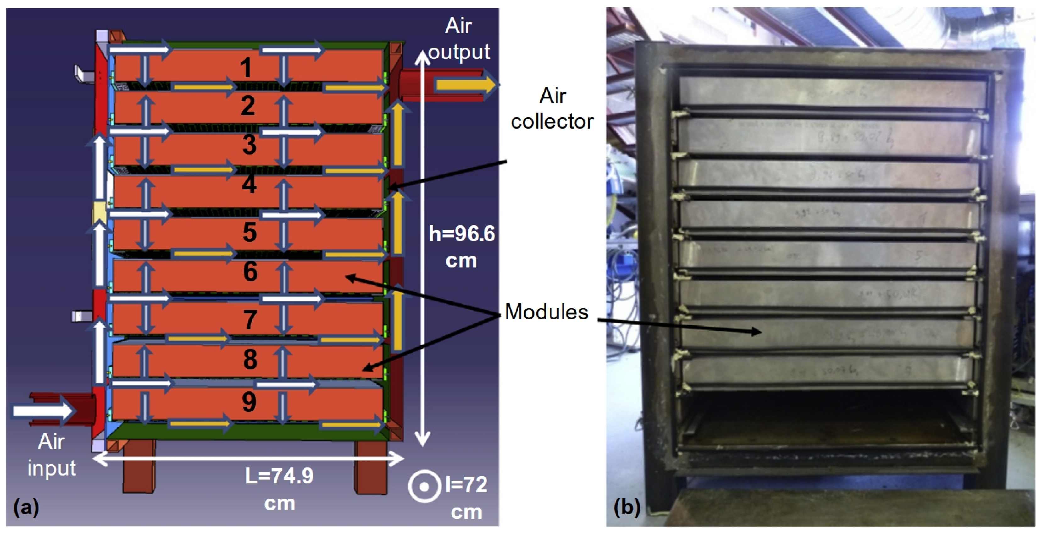
- Weber, R.; Asenbeck, S.; Kerskes, H.; Drück, H. SolSpaces—Testing and Performance Analysis of a Segmented Sorption Store for Solar Thermal Space Heating. Energy Procedia 2016, 91, 250–258. [Google Scholar] [CrossRef]
- SolSpaces 2.0 | Institute for Building Energetics, Thermotechnology and Energy Storage | University of Stuttgart. Available online: https://www.igte.uni-stuttgart.de/en/research/research_hrt/completed-projects/solspaces2/ (accessed on 22 April 2025).
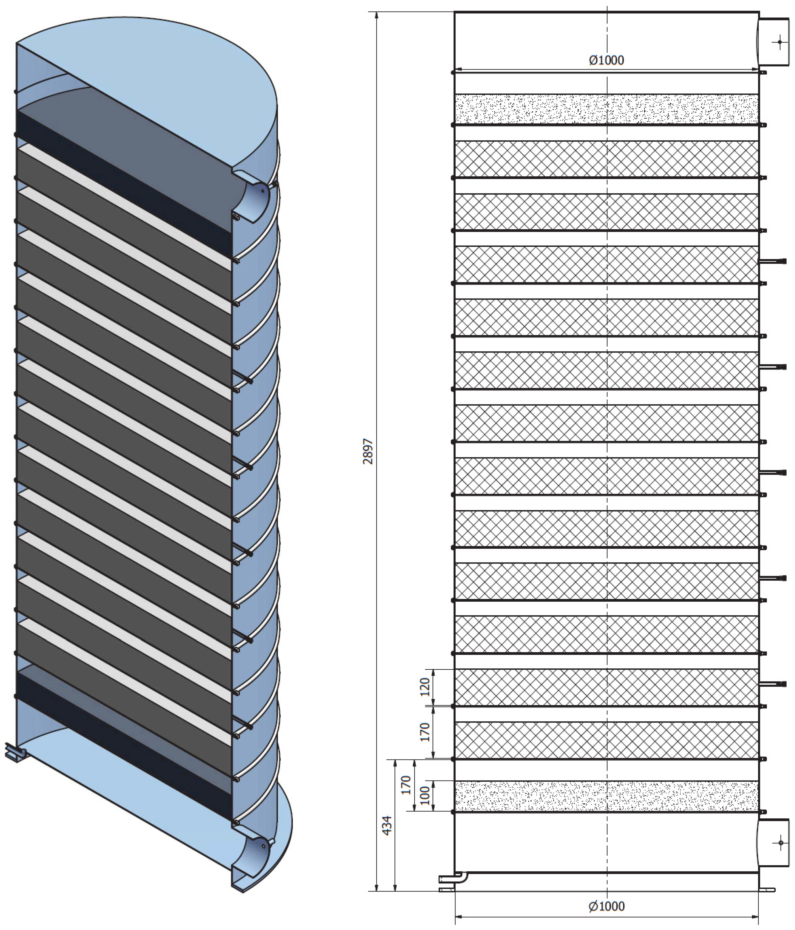
- Bujalski, M.; Starosielec, B. Z Laboratorium Do Rzeczywistości. Sezonowe Magazynowanie Energii Cieplnej w Bateriach Termochemicznych. Energetyka Ciepl. Zawodowa 2017, 2, 56–61. (in Polish). [Google Scholar]
- de Jong, A.-J.; van Vliet, L.; Hoegaerts, C.; Roelands, M.; Cuypers, R. Thermochemical Heat Storage—From Reaction Storage Density to System Storage Density. Energy Procedia 2016, 91, 128–137. [Google Scholar] [CrossRef]
- Mostostal Warszawa Develops the First World’s Termochemical Battery. Available online: https://www.mostostal.waw.pl/en/company/news/mostostal-warszawa-opracowuje-pierwsza-na-swiecie- (accessed on 22 April 2025).
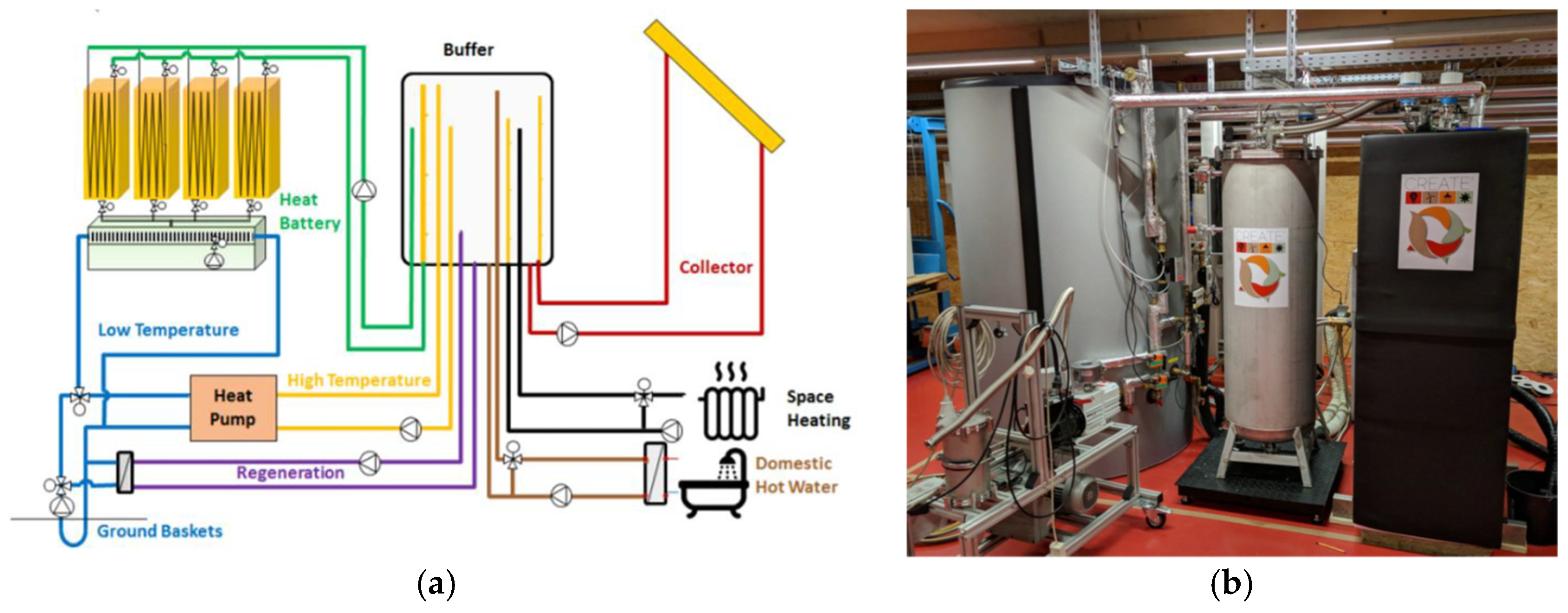
- CREATE Project, Homepage. Available online: http://www.createproject.eu/ (accessed on 22 April 2025).
- Kerskes, H.; Mette, B.; Bertsch, F.; Asenbeck, S.; Drück, H. Chemical Energy Storage Using Reversible Solid/Gas-Reactions (CWS)—Results of the Research Project. Energy Procedia 2012, 30, 294–304. [Google Scholar] [CrossRef]
- Michel, B.; Mazet, N.; Neveu, P. Experimental Investigation of an Innovative Thermochemical Process Operating with a Hydrate Salt and Moist Air for Thermal Storage of Solar Energy: Global Performance. Appl. Energy 2014, 129, 177–186. [Google Scholar] [CrossRef]
- Farcot, L.; Le Pierrès, N.; Fourmigué, J.-F. Experimental Investigation of a Moving-Bed Heat Storage Thermochemical Reactor with SrBr2/H2O Couple. J. Energy Storage 2019, 26, 101009. [Google Scholar] [CrossRef]
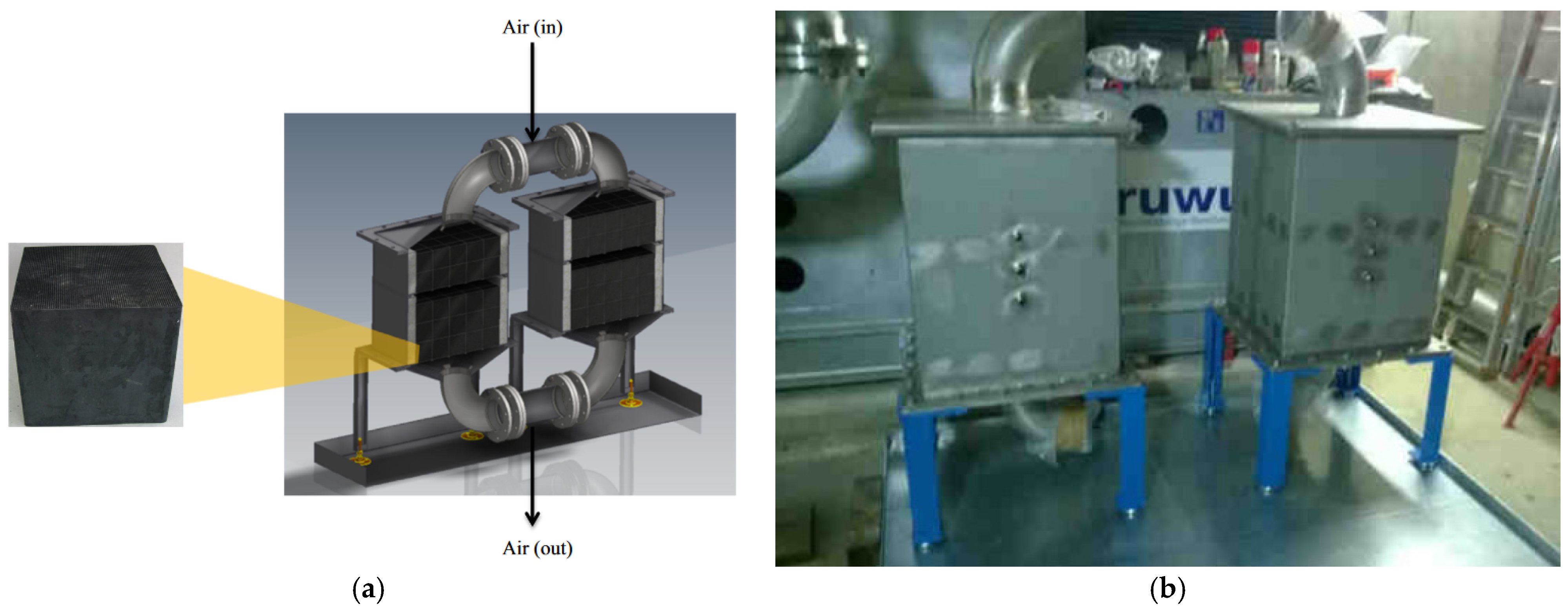
- Karagiannakis, G. Final Report: Publishable Summary. Redox Materials Based Structured Reactors/Heat Exchangers for Thermochemical Heat Storage Systems in Concentrated Solar Power Plants; Centre for Research and Technology Hellas: Thessaloniki, Greece, 2016. [Google Scholar]
- Singh, A.; Tescari, S.; Lantin, G.; Agrafiotis, C.; Roeb, M.; Sattler, C. Solar Thermochemical Heat Storage via the Co3O4/CoO Looping Cycle: Storage Reactor Modelling and Experimental Validation. Sol. Energy 2017, 144, 453–465. [Google Scholar] [CrossRef]
- Billig, T.; Lasek, J.; Zuwała, J.; Fryza, R. Variable Capacity Heat Storage 2024. Patent PL245575B1, 2 September 2024. Available online: https://worldwide.espacenet.com/patent/search/family/084426782/publication/PL245575B1?q=PL438020A1 (accessed on 28 April 2025).
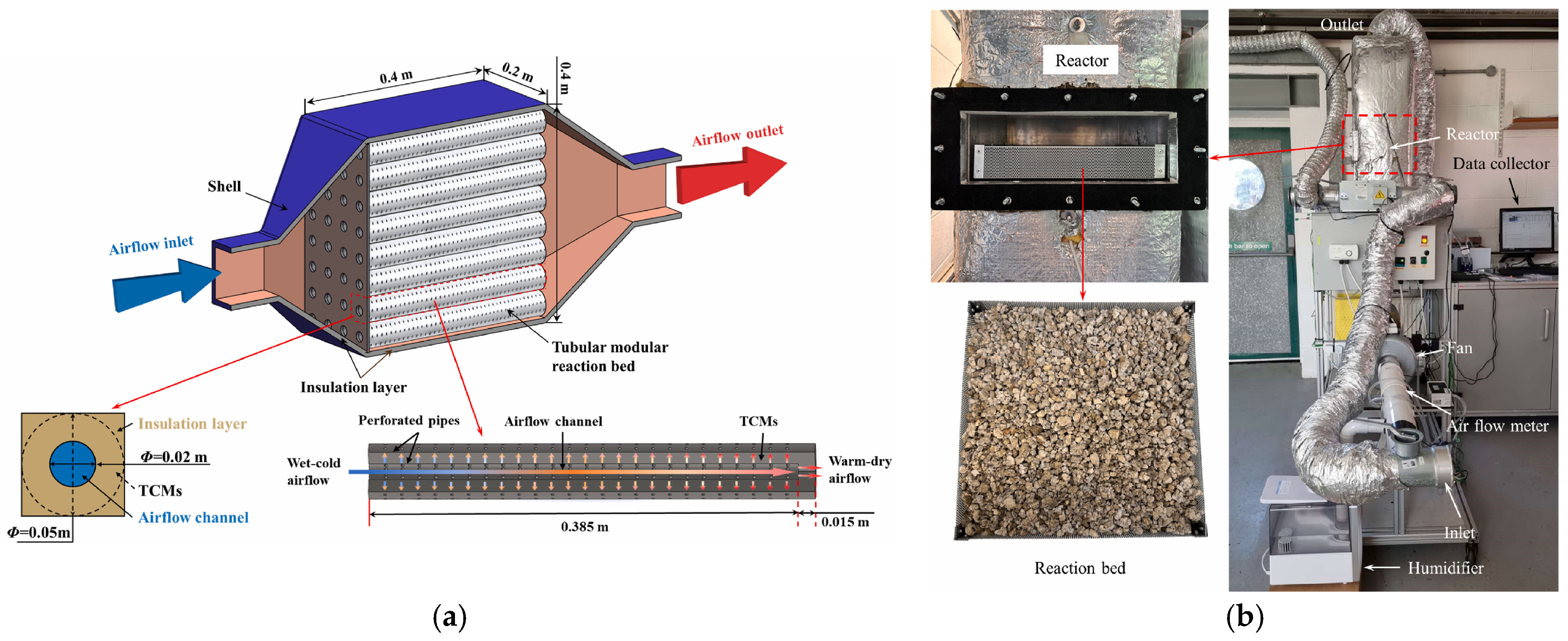
- Zhang, Y.; Hu, M.; Chen, Z.; Su, Y.; Riffat, S. Exploring a Novel Tubular-Type Modular Reactor for Solar-Driven Thermochemical Energy Storage. Renew. Energy 2024, 221, 119767. [Google Scholar] [CrossRef]
- Wang, C.; Ma, H.; Ahmad, A.; Yang, H.; Ji, M.; Zou, B.; Nie, B.; Chen, J.; Tong, L.; Wang, L.; et al. Discharging Behavior of a Fixed-Bed Thermochemical Reactor under Different Charging Conditions: Modelling and Experimental Validation. Energies 2022, 15, 8377. [Google Scholar] [CrossRef]


| Material | Heat Capacity, J/kg·°C | Average Density, kg/m3 |
|---|---|---|
| Sensible heat storage (SHS) [8,12,14] | ||
| Alumina (Al2O3) | 1180 | 2240 |
| Aluminum | 896 | 2707 |
| Brick | 840 | 1600 |
| Cast iron | 600 | 7800 |
| Cast steel | 600 | 7800 |
| Copper | 385 | 8954 |
| Engine oil | 1880 | 888 |
| Glass | 837 | 2710 |
| Granite | 892 | 2750 |
| Graphite | 1424 | 2250 |
| Limestone | 741 | 2500 |
| Reinforced concrete | 1500 | 2500 |
| Rock | 879–960 | 2560 |
| Sand | 830 | 1602 |
| Silicone oil | 2100 | 900 |
| Sunflower oil | 2969 | 753 |
| Therminol 55 | 2400 | - |
| Water | 4190 | 1000 |
| Latent heat storage (LHS) [15,16,17,18,19,20,21,22,23,24] | ||
| Melting temperature, °C | Latent heat, kJ/kg | |
| Organic compounds | ||
| Tetradecane | 5.9 | 258 |
| Hexadecane | 18 | 211–236 |
| Parraffin Rubitherm RT60 | 58–60 | 214 |
| Parafin | 64 | 210 |
| Lauric acid | 41–44 | 176–211 |
| Myristic acid | 49–54 | 175–204 |
| Stearic acid | 65–71 | 155–210 |
| Palmitic acid | 54–64 | 188–201 |
| Paraffin RT110 (Rubitherm) | 112 | 285 |
| Erythritol | 118–120 | 340 |
| Salicylic acid | 159 | 199 |
| Urea | 134 | 250 |
| D-mannitol | 167 | 326 |
| Salt hydrates | ||
| CaCl2·6H2O | 29 | 191 |
| Na2SO4·10H2O | 32 | 254 |
| Na2S2O3·5H2O | 48 | 209 |
| Sodium acetate trihydrate | 58 | 266 |
| 80% Mg(NO3)2·6H2O, 20% MgCl2·6H2O | 60 | 150 |
| Mg(NO3)2·6H2O | 89 | 167–175 |
| AlK(SO4)2·12H2O | 91 | 269 |
| MgCl2·6H2O | 117 | 169 |
| Salt mixtures and eutectics | ||
| Hitec XL (48 CN, 45% PN, 7% SN) | 120 | 55 |
| 30% LN,60% PN, 10% CN | 132 | - |
| 67% PN, 33% LN | 133 | 170 |
| Hitec (7% SN, 53% PN, 30% NaNO2) | 142 | 80 |
| 55.4% LN, 4.5% SN, 40.1% KCl | 160 | 266 |
| 57%LN, 43%SN | 193 | 248 |
| Solar Salt (60% SN/40% PN) | 220–223 | 115 |
| PN/KCl | 320 | 74 |
| 56% KCl, 44% LiCl | 348 | 170 |
| 60% MgCl2, 20.4% KCl, 19.6% NaCl | 380 | 400 |
| LiNaK Carbonate: (32.1% LC, 33.4% SC, 34.5% PC) | 400 | 276 |
| 63% LiF, 37% LiCl | 485 | 403 |
| Metals and their alloys | ||
| Pb | 328 | 23 |
| 48%Mg, 52%Zn | 340 | 180 |
| 59% Al, 33% Mg, 6% Zn | 443 | 310 |
| 66% Al, 34% Mg | 450 | 310 |
| 20% Al, 80% Si | 585 | 460 |
| Al | 660 | 397 |
| 49% Zn, 45% Cu, 6%Mg | 703 | 176 |
| Cu | 1083 | 193 |
| Feature | Salt Hydrate in LHS System (as PCM) | Salt Hydrate in TCES System |
|---|---|---|
| Storage mechanism | Enthalpy of partially dehydration and enthalpy of dissolution and mixing | Enthalpy of dehydration (bond breaking and recombination) |
| Energy release | During solidification | During hydration (water vapor sorption) |
| Energy density | Generally lower than TCES | Generally higher, even 45% higher than the corresponding LHS [99] |
| Heat loss | Prone to self-discharge via heat dissipation | Negligible heat loss during storage |
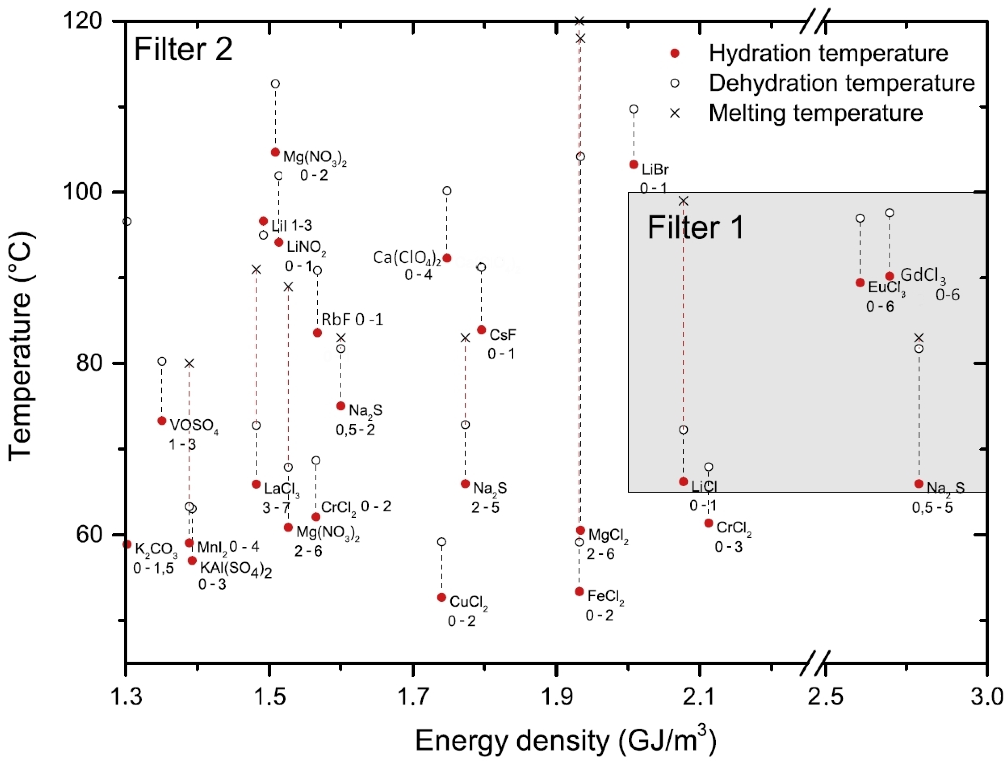
| Parameter | Description and Example Criteria |
|---|---|
| Energy density | Amount of energy stored per unit mass or volume of the salt hydrate. Theoretical energy density is determined by the reaction enthalpy, while practical energy density is influenced by factors such incomplete reactions and system design (open or closed). >500 kWh/m3 (1.8 GJ/m3) for practical deployment. Other filters: >1 GJ/m3 or >2 GJ/m3. |
| Operating temperature (Hydration and dehydration temperature) | The temperature at which energy can be stored or released (dehydration and hydration temperature). It influences the application of TCES system. Dehydration temperature < 100 °C for solar application and <140 °C for waste heat. Temperature of melting should be higher than dehydration. Temperature lift during hydration should be as high as possible. |
| Chemical and thermal properties | The material should not decompose (which can happen at higher temperatures, especially during dehydration) or undergo a hydrolysis reaction. RH of air at operating condition should be lower than DRH. Thermal stable to 150 °C. DRH > 60% (at 25 °C). No decomposition reaction. |
| Cycle stability | The ability of the salt hydrate to maintain its performance over repeated charging and discharging cycles without degradation. It determines the lifetime of the material and costs of stored energy. Stability: >10 stable cycles: hydration/dehydration. |
| Cost and availability | The cost of the salt hydrate material and the overall system cost are critical for economic viability. Good mechanical strength. Price: <3.5 USD/kg or <1–2 €/MJ. |
| Safety and environmental considerations | Materials should non-flammable and non-explosive (strong oxidizer are not preferred). Possibly the lowest corrosivity and non-toxicity for safe operation. It is important that no toxic gases (e.g., HCl, H2S) are released during dehydration. Safety: salt can be applied in open and closed system. |
| Selection Criteria | Selected Salts | Application of TCES | Reference |
|---|---|---|---|
| E > 500 kWh/m3, maximum TDH of 100 °C, material cost of <3.5 USD/kg. | MgSO4, SrBr2, SrCl2, Na3PO4, and MgCl2. | Building heating | Ruby-Jean Clark et al. [82] |
| 1 selection: E > 2 GJ/m3, TH > 65 °C at 12 mbar of H2O, TDH < 100 °C at 20 mbar of H2O. Tm > TDH 2 selection: E > 2 GJ/m3, TH > 50 °C at 12 mbar of H2O, TDH < 120 °C at 20 mbar of H2O. Tm > TDH | 262 salts considered and 563 reactions. 25 salts preselected. The most promising: Na2S, LiCl, EuCl3 and GdCl3. The best salt is K2CO3. | TCM reactor in the built environment. Energy stored 10 GJ, deliver hot tap water at 65 °C and charged in summer using the solar panels. | Donkers et al. [120] |
| Toxic, flammable, explosive materials rejected (80 salts). Discharging temperature 60 °C. E > 480 kWh/m3, Upper limit for the charging of 105 °C. | (45 materials preselected and then evaluated by TGA) The most promising: SrBr2, MgSO4, LaCl3 | store 80 kW h of heat generated by micro-CHP for household applications, in a storage unit of 1 m | N’tskoupoe et al. [83] |
| Rejected materials: harmless, deliquescent, having a side reaction or undergo decomposition, having a Teq > 150 °C at 96 kPa of H2O. Experiment of reversibility: TH > 150 °C at 96 kPa of H2O. TDH (at 5 kPa of H2O) < TH (at 96 kPa of H2O). Stability over 10 cycles | From 308 salts, 32 selected to experimental analysis. Only SrBr2 meets all criteria. | Reintegration of process waste heat up to 300 °C. | Richter et al. [84] |
| E ≥ 1.3 GJ/m3 TDH ≤ 120 °C at 12 mbar of H2O 10 ≥ cycles of hydration/dehydration | Selection from 24 double-salts. (NH4)2Zn(SO4)2·6H2O meets all criteria. | TCES | Kooijman et al. [121] |
| According to Strunz and Nickel mineral classification. Reversibility of charging and discharging up to 140 °C and 250 °C | Selection of minerals as potential TCES hydrates. 29 mineral specimens selected and experimentally evaluated | TCES | Afflerbach et al. [85] |
| Toxicity, energy demands, reaction temperature, stability, reaction hysteresis and reversibility. Three case scenarios T > 30 °C and T > 55 °C discharging temperature, and charring temperature: T < 160 °C. | 454 salts hydrates and 1073 reactions evaluated. Eight salts and nine reactions (K2CO3 0–1.5, LiCl 0–1, NaI 0–2, NaCH3COO 0–3, (NH4)2Zn(SO4)2 0–6, SrBr2 1–6, CaC2O4 0–1, SrCl2 0–1 and 0–2) met all of the criteria. Including salt stabilization: additional four salts: CaBr2, CaCl2, LiBr, LiCl and ZnBr2. | Domestic heating TCES. Using heat sources available in the built environment. | Mazur et al. [63] |
| Three different case scenario and six filters including 12 parameters. Among others: E from >1 to >2 GJ/m3, Price: from EUR <0.5 to EUR <2/MJ. Chemical stability from 30 to 150 °C, hydration temperature < 30 °C, dehydration < 150 °C | 10 salts experimentally validated: CaCl2, Ca(NO3)2, CaSO4, CuSO4, MgCl2, Mg(NO3)2, MgSO4, SrBr2, Zn(NO3)2, K2CO3. The most preferred: MgSO4 Candidates for closed systems: CaSO4 and CuSO4 | TCES | Palacios et al. [100] |
| Among others, based on E (gravimetric and volumetric). Temperature hysteresis could not be larger than 50 °C. Metal salts more expensive than Li rejected. Unstable compounds eliminated (with distances > 50 meV/atom) | 265 hydration reactions were screened. Novel salt: CrF3·9H2O 17 promising reactions. Novel compounds as TCES materials: AlF3·9H2O, CrF3·9H2O, FeBr2·4H2O, Na2Cu(OH)4, NaOH·7H2O, and ZnCl2·3H2O | TCES Three temperature operating ranges: <100 °C, 100–300 °C, >300 °C | Kiyabu et al. [122] |
| Salt Hydrate | nH2O | TDH, °C | TH, °C | Tm, °C | dHS, kg/m3 | E, GJ/m3 | ΔHR, kJ/molH2O | Remarks | Ref. |
|---|---|---|---|---|---|---|---|---|---|
| Al2(SO4)3·18H2O | 8 | 100 | 88 | 1690 | 1.41 | 55.4 | Very low temperature rise during hydration. Not fully dehydrated even at 300 °C. | [83] | |
| Al2(SO4)3·6H2O | |||||||||
| 0 | 306 * | 293 | 3.19 | [120] | |||||
| K2CO3·1.5H2O | 0 | 93 | 2043 | 1.3 | 61–66 | Quite low energy. Good reversibility and excellent stability. Slow hydration rates. Promising material. | [126] | ||
| >80 | 2150 | 1.24 | [83] | ||||||
| 65 | 59 | >150 | 2180 | 1.3 O/0.96 C | [120] | ||||
| 120 (2% RH at 25 °C) | 25 (38% RH) | [127] | |||||||
| KAl(SO4)2·3H2O | 0 | 63 * | 57 | 92 | 2200 | 1.39 O/1.01 C | 55 | [120] | |
| CaCl2·6H2O | 1 | 45 | 29 | 1710 | 2.16 | 55 | Very low Tm and < TDH. Gel formation during hydration. Deliquescence. Often used in composites (see Section 4.1). | [83] | |
| 71 * | 32 | 1840 | 2.58 O | [120] | |||||
| CaCl2·2H2O | 0 | 1.44 | [128] | ||||||
| CaBr2·6H2O | 4 | 63 | 38 | 2295 | 2.64 | 62 | Tm < TDH | [83] | |
| 0 | 81 | 74 | 2.67 | [120] | |||||
| Ca(NO3)2·4H2O | 2 | 44 * | 38 | 1820 | 0.86 | 52 | Strong oxidizer | [120] | |
| 0 | 50 | 43 | 1.71 | ||||||
| CaSO4·0.5H2O | 0 | 120 | 2320 | 0.51 | 61–66 | Poor reversibility in practical applications. | [84] | ||
| 102 * | 94 | 0.60 | [120] | ||||||
| MgCl2·6H2O | 4 | <100, 57 | 1569 | 1.1 | 72 | HCl can be produced during dehydration > 115°C. Deliquescence. Low cost. Promising material when using in composites (see Section 4.1) | [82] | ||
| 2 | 96 | 1.97 | [129] | ||||||
| 2 | 104 * | 61 | 117 | 1560 | 1.93 O/1.24 C | [83] | |||
| 2.48 | [120] | ||||||||
| 1 | 117 | [128] | |||||||
| MgSO4·7H2O | 1 | 85 | 49 | 1670 | 2.27 | 56 | Good hydration only under high RH. Stable under cycling. High energy density. Needs a lot of hydration time. Slow kinetic of hydration and low temperature lift. | [83] | |
| 24 | 2.27 O | [120] | |||||||
| MgSO4·6H2O | 1 | 22 | 2.08 O | 55 | |||||
| MgSO4·6H2O | 2 | 130 (5% RH) | 88–93 | 2.0 | [83,110] | ||||
| 1.3 | |||||||||
| MgBr2·6H2O | 4 | <100 | 152–165 | 2000 | 0.99 | 72 | [83] | ||
| MgBr2·H2O | 0 | 116 * | 109 | 1569 | 1.19 | 69 | [120] | ||
| Mg(NO3)2·6H2O | 2 | 68 * | 61 | - | 1670 | 1.53 O/1.04 C | 58 | Decomposition can occur and release of N2 | [120] |
| LaCl3·7H2O | 1 | 86–105 | 40 | 2230 | 2.13 | 59 | High cost. | [83] | |
| 3 | 73 * | 66 | 1.48 O/1.03 | [120] | |||||
| 0 | 158 * | 48 | 2.41 | ||||||
| La(NO3)3·6H2O | 1.5 | <100 | 40 | 2347 | 0.98 | 58 | Oxidizer, high cost. | [83] | |
| 1.41 | |||||||||
| LiCl·H2O | 0 | 99 | 1700 | 1.75 | Quite expensive and high deliquescence. Corrosive. | [83] | |||
| 72 * | 66 | 1760 | 2.08 O/1.36 C | 71.3 | [120] | ||||
| 87 | 62 | [82] | |||||||
| 1780 | |||||||||
| LiNO3·3H2O | 0 | <100 | 30 | 1550 | 1.24 | 55 | Oxidant, expensive | [83] | |
| 34 | 28 | 2.13 O | 55.6 | [120] | |||||
| LiBr·H2O | 0 | 110 * | 103 | - | 2670 | 2.01 O/1.37 C | 69.5 | Deliquescence | [120] |
| 90 | 1570 | 70 | [82] | ||||||
| SrCl2·6H2O | 2 | 42–50 | 1930 | 2.02 | Stability under cycling, fully reversible under 65% RH, 22 °C. Very promising. | [82] | |||
| 0 | 1960 | 2.51 | 57 | [83] | |||||
| 2 | 33 * | 27 | 1.58 | 23.7 | [120] | ||||
| 0 | 202 * | 28 | 61 | 2.99 | |||||
| 0 | 2.4 ± 0.1 | [130] | |||||||
| SrBr2·6H2O | 1 | 90 | Stability under 10 cycles. Reversible and reasonable energy density. Total dehydration from 80 °C. Very promising. Expensive. Irritant. | [82] | |||||
| 1 | 2386 | 2.26 | 67.4 | [83] | |||||
| 1 | 1900 | 0.5 | [84] | ||||||
| 2 | 33 | 28 | 1.61 | 54.6 | [120] | ||||
| 0 | 122 | 48 | 88 | 2.49 | |||||
| CuSO4·5H2O | 1 | 40 | 30 | 2.05 | Maximum temperature of hydration is 60 °C. Harmful. | [120] | |||
| 65–94 | 2286 | 2.06 | 57 | [84] | |||||
| Na3PO4·12H2O | 8/7/6/4/0.5 | 37/46/52/78/84 | 1620 | 3.6 | 53 | Not reversible. Uptake of 6 mol H2O at RH 60–65% and 20–22 °C. | [82] | ||
| 0 | 33 | 27 | 55 | [120] | |||||
| Na2SO4·7H2O | 0 | 81.8 | 23 | - | 2.21 | 53.7 | Low melting point of hydrates (about 30 °C). Require high RH to fully hydrate | [82,131] | |
| Na2SO4·10H2O | 0 | 32 | 2.48 | 50.5 | [120,132] | ||||
| Na2S2O3·5H2O | 4/3/1 | 44.1/54.6/71.6 | 56 | Formation of layer which inhibit the water release | [83] | ||||
| 0 | 32 | 26 | 48 | 1690 | 1.91 | 54 | [120] | ||
| Na2S·9H2O | 5/2/0.5 | 60/92/100 | 1430 | 2.66 | 62 | Toxic, corrosive, H2S can be released. Partial melting. | [83] | ||
| Na2S·5H2O | 0.5 | 82 * | 66 | 2.79 O | [120] | ||||
| Zn(NO3)2·6H2O | 4 | 39 | 34 | 36 | 0.86 | 62.1 | [120,132] | ||
| ZnSO4·6H2O | 1 | 27 * | 21 | 1970 | 2.0 | 52.1 | [120] |
| Reaction (Solid ⇄ Solid + Gas) | Theoretical Energy Density (GJ/m3) | Experimental Energy Density (GJ/m3) | Reaction Temperature (Charging/Discharging) (°C) | Ref. |
|---|---|---|---|---|
| MgCl2·6H2O ⇄ MgCl2·H2O + 5H2O | 2.5 | 0.71 | 150/30–50 * | [123,133] |
| MgCl2·4H2O ⇄ MgCl2·2H2O + 2H2O | 1.27 | 1.10 | 118/NA * | [134] |
| CaCl2·2H2O ⇄ CaCl2 + 2H2O | 1.1 | NA | 95 | [123] |
| CaCl2·6H2O ⇄ CaCl2 + 6H2O | 2.8 | 1.47 | NA/200 | [135] |
| Al2(SO4)3·6H2O ⇄ Al2(SO4)3 + 6H2O | 1.9 | NA | 150 | [123] |
| MgSO4·6H2O ⇄ MgSO4·H2O + 5H2O | 2.37 | 1.83; 0.38 | 72/NA *; NA/150 °C * | [133,136] |
| Na2S2·5H2O ⇄ Na2S2·1/2H2O + 9/2H2O | 2.7 | NA | 80/65 * | [137] |
| SrBr2·6H2O ⇄ SrBr2·H2O + 5H2O | 2.3 | 2.08 | NA/23.5 ** | [138] |
| Li2SO4·H2O ⇄ Li2SO4 + H2O | 0.92 | 0.80 | 103/NA | [134] |
| CuSO4·5H2O ⇄ CuSO4·H2O + 4H2O | 2.07 | 1.85 | 92/NA | [134] |
| Salt | Low Temperature Application (0 °C) | Indoor Temperature Application (20 °C) |
|---|---|---|
| MgSO4·7H2O | 35–95% RH | 43–92% RH |
| SrCl2·6H2O | 25–78% RH | 33–72% RH |
| Na3PO4·12H2O | – | >28% RH |
| SrBr2·6H2O | 5–65% RH | 9–46% RH |
| MgCl2·6H2O | – | 4–33% RH |
| Salt | Moles of Water (Hydration–Dehydration) | Density of Hydrate, kg/m3 | Theoretical Energy Density, GJ/m3 | Estimated Price *, €/kg | Price of Stored Energy, €/GJ |
|---|---|---|---|---|---|
| CaCl2 | 6–1 | 1710 | 2.16 | 0.16 | 142 |
| 6–2 | 1.85 | 166 | |||
| 6–0 | 2.82 | 109 | |||
| CaBr2 | 6–0.3 | 2295 | 2.64 | 3.5 | 3047 |
| LaCl3 | 7–1 | 2223 | 2.13 | 2.2 | 2297 |
| La(NO3)3 | 6–1.5 | 2347 | 1.41 | 3.5 | 5821 |
| LiCl | 1–0 | 1700 | 1.75 | 10 | 9713 |
| MgBr2 | 6–4 | 2000 | 0.99 | 3.5 | 7045 |
| MgCl2 | 6–2 | 1569 | 1.97 | 0.15 | 120 |
| 6–1 | 3.14 | 75 | |||
| MgSO4 | 7–1 | 1690 | 1.90 | 0.2 | 177 |
| 7–0 | 1690 | 2.81 | 120 | ||
| 6–0.1 | 1810 | 2.20 | 165 | ||
| 6–1 | 1810 | 1.69 | 214 | ||
| SrBr2 | 6–1 | 2386 | 2.26 | 7 | 7393 |
| SrCl2 | 6–0 | 1960 | 2.51 | 2 | 1561 |
| Na2S | 9–0 | 1430 | 3.17 | 0.45 | 203 |
| 5–0 | 1580 | 2.93 | 243 |
| Material | Desorption Temperature, °C | Adsorbed Water, kg/kg | Maximum Temperature in the Storage, °C | Energy Density, Wh/kg | V Macro, cm3/g | V Meso, cm3/g | Pore Size | λ (W/mK) |
|---|---|---|---|---|---|---|---|---|
| LiLSX [171] | 200 | 0.24 | 107 | 225 | - | - | - | - |
| NaLSX [171] | 200 | 0.23 | 97 | 185 | - | - | - | - |
| SAPO [171] | 100, 150 | 0.23 | 72 | 154 | - | - | - | - |
| Silica gel [171] | 120 | 0.18 | 123 | 62 | - | - | - | - |
| Silica gel [180,181] | - | 0.35 | - | 240 | 1.310 | 0.381 | 2.45 nm | 0.0569 |
| Vermiculite [180,181] | - | <0.1 | - | - | 4.110 | 0.017 | 3.68 µm | 0.0527 |
| Zeolite 13X [180,181] | >180 | 0.30 | - | 310–680 | 1.527 | 0.292 | 1.21 nm | 0.0737 |
| Zeolite 13X [159] | - | 0.17–0.22 50–80% RH | - | - | - | - | 3.36 nm | - |
| Activated carbon [180,181] | - | 0.35 | - | - | 2.365 | 0.395 | 1.98 nm | 0.0790 |
| Salt and Content in the Composite | Porous Matrix | Method of Preparation | Major Results and Other Information | Reference (Main Author and Date) |
|---|---|---|---|---|
| CaCl2, 16–66% | Macroporous vermiculite (V), expanded perlite (EP), pumice, mesoporous silica gel (SG), microporous Zeolite 13X | Vacuum wet impregnation, centrifugal draining and drying at 150 °C for 24 h. | For V-66%CaCl2 and EP-69%CaCl2, E = 0.55–0.65 GJ/m3 but slow reaction kinetics. For SG-CaCl2: superior reaction rates, temperature lift of 16 °C at 50% RH. High pressure drop in case of SG-CaCl2. The most promising for larger scale systems is EP-CaCl2. | Chen, 2025 [201] |
| CaCl2 | AC four types | Wet impregnation and vacuum freeze drying | E = 2039 kJ/kg for AC with 43.4% of CaCl2. Enthalpy of 42.18 kJ/molH2O. Slight decline in water absorption after 25 cycles. AC host matrices enhance low-temperature water desorption. The best water adsorption of 1.07 g/g. | Zhang, 2024 [167] |
| CaCl2 62–63% | EG (novel design of perforated EG block) | Molten salt impregnation for 72 h and dried at 150 °C | E in the range of 135–277 kWh/m3 (of material) or 96–197 kWh/m3 (of reactor). Conditions in the reactor: (0.01 kgH2O/kg air, 20 °C, gas flow rate of 100–400 L/min. Temperature lift up to 24 °C. Impressive 90 hydration/dehydration test and material remained stable. Test of block: hydration at 20 °C and 40% RH for 17 h, dehydration at 150 °C overnight. | Galazutdinova, 2024 [187] |
| CaCl2, 63–77% | Graphite and sodium alginate matrix | Wet impregnation and mould method. | Energy density in the range of 1052–1281 kJ/kg. Salt with higher salt content had reduced energy efficiency. Thermal conductivity about 0.33 W/mK. | Reynolds, 2024 [202] |
| CaCl2 46–50.4% | Mesoporous carbon CMK-3. AC and EG. | Wet impregnation and vacuum drying in oven 150 °C | Excellent stability after 25 cycles. Promising composite below 120 °C. E = 2037 kJ/kg. | Gao, 2023 [168] |
| CaCl2, 32% and 42% | Silica-PEG | Sol–gel method | E = 782 kJ/kg, what is 70% higher than zeolite. Water adsorption of 0.37 g/g at regeneration temperature of 130 °C. Absorption at 30 °C and 42% RH. Kinetics slower than zeolite 13X. Lab-scale open reactor. 4 cycles were performed effectively. | Berut, 2023 [203] |
| CaCl2, 23–58% | EG | Dehydration < 120 °C. E = 1638 J/g. Water adsorption of 0.79 g/g. | Gao 2022 [204] | |
| CaCl2, 25–60% | Aluminium fumarate MOF | Synthesis of MOF | Maximum water sorption of 0.68 g/g and heat of sorption of 1840 J/g for 58% CaCl2/MOF. | Touloumet, 2021 [205] |
| CaCl2, 15% | Silica gel, alumina, bentonite | Incipient wetness impregnation. Dried at 110 °C and dehydrated at 260 °C. | The highest water adsorption of 0.27 g/g for silica gel-CaCl2. Average heat of dehydration E = 746 J/g (of sample). Alumina-CaCl2: water adsorption of 0.17 g/g and E = 576 J/g. Bentonite-CaCl2: water adsorption of 0.23 g/g and E = 719 J/g. | Jabbari-Hichri, 2017 [113] |
| CaCl2 | AC Attapulgite (Palygorskite) | Wet impregnation using 30% CaCl2 | Water adsorption of 0.223 g/g, E = 580 kJ/kg. Maximum temperature in the storage 77 °C. Water adsorption of 0.18 g/g, E = 637 kJ/kg. Maximum temperature in the storage 63 °C. Apparatus: thermochemical storage unit for 1 kg of material | Jänchen, 2005 [171] |
| MgSO4, 7–13.4% | Zeolites 3A, 5A, 13X | Wet impregnation in 10% and 20% MgSO4 for 48 h. Dried at 150 °C and 300 °C. | The best composite was MgSO4-Zeolite 13X. Water sorption of 0.21 g/g (24% higher than pure Zeolite 13X). E = 438.4 kJ/kg. Improvement of the mass transfer. Hydration at 60% RH at 25 °C. | Li, 2024 [206] |
| MgSO4, 1–7.6% | Bead activated carbon (BAC) | Wet impregnation. Dried at 150 °C for 12 h. | Hydration at 30 °C and 60% RH and dehydration at 150 °C. Heat of hydration 920 J/g (for 7.6% MgSO4-BAC). Water adsorption of 0.3 g/g | Nguyen, 2023 [71] |
| MgSO4, 4.4–19.5% | Biochar from corn cobs | Wet impregnation | The best water adsorption of 0.24 g/g (for 19.5% MgSO4). E = 635 kJ/kg (Hydration at 30 °C and 6%RH). | Nguyen, 2023 [207] |
| MgSO4 | Hydroxyapatite (HAP) | HAP synthesis by co-precipitation. Wet impregnation | Maximum water sorption of 0.14 g/g and heat of hydration of 464 J/g for 20% MgSO4 composite. Good long-term cycling operation over 20 cycles; dehydration at 150 °C and hydration at 30 °C and 60% RH. | Nguyen, 2022 [208] |
| MgSO4, 4–43% | AC | Incipient wetness impregnation | Increasing hydration enthalpy with increasing content of MgSO4 up to 30%. Hydration at 30% and 60%RH, at temp. 30 °C for 20 h. E max of 1.32 kJ/g (of dry material) at 60% RH for 30% MgSO4/AC. Dehydration at 150 °C. Stable after 8 cycles. Water adsorption up to0.24 g/g. Thermal conductivity 0.43 W/mK for 30% MgSO4/AC. | Bennici, 2022 [209] |
| MgSO4, 30–50%, 15–30% for Zeolite 13X | Mesostructured cellular foam MCF and Zeolite 13X | MCF by Microemulation templating method. Composite by wet impregnation. Dried at 150 °C under vacuum for 4 h. | 30 °C, water vapor pressure of 25 mbar, Dehydration tests at 150 °C (1 °C/min) and water vapor pressure of 25 mbar. Slightly lower dehydration temperature than pure salt. 50% adsorbed water war removed at 65 °C and 70% at 75 °C (90 °C is necessary in case of pure salt). 3D porous structure exhibits higher water adsorption capacity and faster adsorption rate than mesoporous silica with 2D porous structure. | Liu, 2022 [183] |
| MgSO4, 50–80% | EG | Wet impregnation for 24 h. Dried in oven at 150 °C. Cylindrical mold. | Low and medium TES storage, open systems. Hydration tests at 85% RH at 25 °C for 12 h. The most promising was 60% MgSO4-EG; its heat of reaction of 718.0 kJ/kg, thermal conductivity of 0.6696 W/mK, BET 15 cm2/g. BET for pure EG of 44 cm2/g. Improvement of hydration time (shortened to about ¼) and significant increase in thermal conductivity (by 84.8%). | Miao, 2021 [173] |
| MgSO4, 30% and 60%. | Diatomite | Dry impregnation. Dried at 250 °C for 12 h. Formed into tablets. | E = 773 kJ/kg over 80–150 °C, water uptake of 0.37 g/g (for 60% MgSO4/diatomite) Cycling stability tests: hydration at 25 °C and 85% RH for 10 h. Dehydration at 250 °C for 6 h. | Zhang, 2021 [178] |
| MgSO4, 3–11% | Zeolite 13X | Wet impregnation (in 5–20% MgSO4), Dried at 150 °C for 4 h and at 300 °C for 2 h. | Tests at RH in the range of 50–80% for 25 h at 25 °C. Water adsorption in the range of 0.2–0.32 g/g (at 50–80% RH). The best composite was 15% MgSO4-Zeolite 13X, E = 632 J/g at 80% RH, where for pure zeolite E = 551 J/g. | Weng, 2019 [159] |
| MgSO4, 40–70% | Silicone foam | Silicon foam synthesis from PMHS and PMDS and catalyst | Dehydration at water vapor pressure of 23.4 mbar and temperature up to 150 °C. Silicone foam does not hinder the water vapor diffusion. Progressive loss of salt with increasing compression cycles. | Calabrese, 2019 [210] |
| MgSO4, 2–14% | Zeolites 3A, 4A, 13X | Wet impregnation in 10–20% MgSO4 solution | Water adsorption of 0.25 g/g (13X Zeolite-MgSO4) Test platform with regulated RH and temperature. Temperature lift about 50 °C. | Xu, 2018 [211] |
| MgSO4, 10–25% | Zeolite 13X | Wet impregnation. Dried at 150 °C. | Water adsorption of 0.14 g/g at 30 °C and at 17–19 mbar of water vapor pressure. For optimum composite, i.e., 15% MgSO4-Zeolite, E = 166 kWh/m3 at 50% RH. Minimum 50% RH is required to obtain temperature lift 15 °C in the reactor (200 g of sample). Obtained energy corresponds to 45% of theoretical value. | Hongois, 2011 [161] |
| MgCl2, 86% and 97% | MXene (MX) | Synthesis of MXene. Wet impregnation in 10 and 15% MgCl2 with ultrasonic processing. | Hydration/dehydration enthalpy of 2227 J/g at 85% RH. Water absorption of 1.9 g/g and 2.2 g/g. E = 0.55–0.77 GJ/m3 at 85% RH for 86%Mg/MX and 97% Mg/MX 15%. | Rehman, 2023 [192] |
| MgCl2 | NH2-MIL-88 (Fe) framework coupled with MXene (carbon material) | Synthesis of MOF. Wet impregnation. Dried at 150 °C. | Water adsorption of 2.1 g/g at 75% RH. E = 0.54 GJ/m3 at 75% RH and E = 0.33 GJ/m3 at 65% RH. 20 successive cycling tests. Lower dehydration temperature than pure salt and prevent HCl formation. | Rehman, 2025 [212] |
| MgCl2, 33–36% | Coral aggregate (CA) | Pretreatment of CA. Vacuum and atmospheric impregnation. | Vacuum impregnation led to higher salt loading. E = 74.2 kWh/m3. Compared to Zeolite 13X (the same conditions), E = 121 kWh/m3. | Wang, 2025 [213] |
| MgCl2, 50–90% | Graphene oxide aerogel (GO) | Preparation of GO. Hydrothermal and freeze drying method. | Temperature of dehydration was decreased even by 90 °C. E = 1598 J/g for 90% Mg-GO. | Zhou, 2019 [214] |
| CaCl2 42% MgCl2 33% LiBr 48% CaCl2 31% | Mesoporous silica gel and alumina | Wet impregnation and samples molded under pressure of 150–200 bar | The steep increase in composite thermal conductivity occurs at the same fraction of pore volume occupied by the salt solution, regardless of the amount of salt trapped. | Tanashev, 2013 [215] |
| SrCl2, 9.9–21.6% | Activated alumina, Al2O3 | Vacuum impregnation in 10–30% SrCl2. | The best 20.95% SrCl2-Al2O3. E = 141 kWh/m3 (on the reactor level) and 150 kWh/m3 (on material level). Water uptake of 0.282 g/g at 20 °C and 70%RH. Lower activation energy and faster dehydration than pure salt. Stability over 10 cycles. Energy efficiency up to 93.8%. Bench-scale reactor. Temperature lift of 24 °C. | Yang, 2025 [216] |
| SrCl2, 35–60% | Cement | Mixing with Portland cement powder. | Dehydration of SrCl2-cement can occur below 90 °C. Average E = 0.49 GJ/m3 for 50% SrCl2. Maximum outlet temperature in the range of 32–37 °C. Lab scale open packed bed reactor. Comparison to Zeolite 13X. | Clark, 2021 [217] |
| SrCl2 40% and 14% (in pumice) | Expanded clay and pumice | Wet impregnation | E = 29 kWh/m3 (0.104 GJ/m3) for Clay-SrCl2 40%. E = 7.3 kWh/m3 (0.026 GJ/m3) for pumice-14% SrCl2. Impregnation did not affect salt dehydration. Decreasing power output during 4 run for clay composite. Better cycling stability in case of pumice. Maximum air lift temperature of 10 °C. Lab scale open packed bed reactor. | Mehrabadi, 2018 [194] |
| SrBr2, 15–45% | EV | Wet impregnation method. Dried at 120 °C for 12 h. | For 45% SrBr2-EV, Water adsorption of 0.6 g/g at 30 °C and 60% RH. Desorption enthalpy of 645 J/g. | Ding, 2021 [218] |
| SrBr2, 63% | MOF MIL-101 (Cr) | Wet impregnation in 20–30% SrBr2 solution. Dried at 100 °C for 4 h. | The best performance for 63% SrBr2. Water adsorption of 0.303 g/g (of dry sample) and E = 233 kWh/m3 at pH2O of 1.25 kPa and 30 °C. Desorption at 80 °C. | D’Ans, 2019 [194] |
| SrBr2 58% | Silica gel | Incipient wetness impregnation using 40% SrBr2, for 1 h and then dried at 200 °C | E = 203 kWh/m3 (0.731 GJ/m3) Adsorption at 30 °C and desorption at 80 °C, pH2O of 13.5 mbar. Water adsorption of 0.22 g/g. High cycling stability. Average pore diameter in composite of 21 nm. | Courbon, 2017 [164] |
| SrBr2,30–63% | EV | Wet impregnation method in 10–40% SrBr2. Dried at 120 °C | 63% SrBr2-EV, E = 105 kWh/m3 Hydration at 30 °C and 60% RH. The best water uptake up to 0.5 g/g. | Zhang, 2016 [175] |
| SrBr2, 40% and 80% | Graphite Consolidated composite * | Incipient wetness impregnation. Drying at 200 °C. Form in tablets of 13 mm diameter and thickens 1–2 mm. | For 40% and 80% SrBr2, heat of reaction 417 kJ/kg and 798 kJ/kg, and thermal conductivity 2.30 and 1.30, respectively. Pure SrBr2 E = 417 kJ/kg and thermal conductivity of 0.38 W/mK. Water uptake from 0.2 to 0.35 g/g. | Cammarata, 2018 [174] |
| SrBr2 | Expanded natural graphite (EG), 6–10% Consolidated composite * | Wet impregnation. Form in tablets (40 × 40 × 10 mm). | 1 kWh lab scale system. Temperature of charging and discharging were 80 °C and 35 °C, respectively. E = 189 kWh/m3. Sorption heat storage is about 59% of theoretical value. Heat storage efficiency of 91%. | Zhao, 2016 [219] |
| LiCl, 42% | Highly porous silica, HPS (with large pore volume) | HPS synthesized. Vacuum impregnation method. | Water adsorption of 0.53 g/g. Energy storage of 1.4 kJ/g. Very stable operation during hydration/dehydration. | Cherpakova, 2025 [220] |
| LiCl, 28–35.4% | Mesoporous silica gel | Dry impregnation. Drying at 160 °C for 24 h | The maximum E = 1200 J/g (of dry sample) for 35% LiCl-composite (0.65 GJ/m3). Leakage can occur in case of 35% LiCl which limits practical applications. | Frazzica, 2020 [221] |
| LiCl | Expanded Vermiculite | Wet impregnation | Specified for seasonal heat storage. E = 224 kW h/m3 (0.81 GJ/m3) and 253 kW h/m3 (0.91 GJ/m3) for seasonal and daily seasonal heat storage cycles at the charging temperature in the range of 75–85 °C. | Grekova, 2017 [177] |
| LiCl, 93.6% | EG Consolidated composite *. | Wet impregnation | E = 65.3 kWh/m3 (0.235 GJ/m3) charging at 85 °C and discharging at 40 °C. Experimental closed system reactor 10 kWh. Heat storage efficiency approximately 94%. Thermal conductivity 2.25 W/mK, bulk density of 510 kg/m3. | Zhao, 2016 [222] |
| LiCl, 42–53% | Carbon Nano-tubes (CNTs) | Wet impregnation, dried at 160 °C for 12 h. | For 42% LiCl-CNT, E = 470 Wh/kg at 35 °C and water vapor pressure of 0.87 kPa. Desorption at 75 °C. | Grekova, 2016 [172] |
| LiCl, 5–20% | Expanded Vermiculite (EV) | Wet impregnation in 5–40% LiCl solution for 48 h. Dried at 120 °C. | Sorption at 30 °C and 60% RH, EV-LiCl20 selected as optimal composite with water adsorption of 1.41 g/g and E = 171.6 kWh/m3. Maximum threshold concentration in composite is 32.6% or leakage may occur. | Zhang, 2016 [223] |
| LiCl, 6.5–43.6% | Silica gel, 2–3 nm (type A) and 8–10 nm (type C) | Wet impregnation in 10–40% LiCl for 12 h at 25 °C. Vacuum filtration. Dried at 120 °C. | Compete water desorption at temperatures from 60 to 100 °C. The most appropriate composite was 30% LiCl and heat storage density = 163.6 kWh/m3 (of composite) and 89.3 kWh/m3 of the system. Adsorption at 30 °C and desorption at 80 °C. | Yu, 2014 [224] |
| K2CO3, 76–95% | EG and octylphenol plyoxyethylene (10) ether—OP-10. Consolidated composite * | Wet impregnation in 50% K2CO3. OP-10 used as surfactant. Dried at 150 °C for 12 h. Molded to tablets. | Thermal conductivities of the composites increased by 9–15 times in comparison with pure salt (0.09 W/mK vs. 2.36 W/mK). E = 138–216 kWh/m3. Water uptake up to 0.18 g/g. | Zhao, 2022 [225] |
| K2CO3, 69% | EV | Wet impregnation in 53% K2CO3 solution, then dried under vacuum. Dried at 160 °C. | E = 0.9 GJ/m3 with deliquescence. Hydration rate higher than pure salt. Very good cycling stability (stable for 47 hydration/dehydration tests) Hydration at 40 °C (for 9 h) and dehydration at 120 °C (for 3 h). Water adsorption of 0.4–1.5 g/g at 30–50 °C and pH2O of 22–117 mbar. | Shkatulov, 2020 [186] |
| Na2S2O3, 62% and 94% | MOF, MIL-101 (Cr) | Synthesis of MOF. Then, wet impregnation in 10% and 30% Na2S2O3. | E = 1099.5 J/g (dehydration) at 120 °C for 61.8% Na2S2O3. Water uptake: 0.04–0.05 g/g at 30 °C and pH2O of 1.27 kPa. Good cyclic stability (9 cycles). | Padamurthy, 2022 [190] |
| Na3PO4 30–80% | AC | Melt impregnation | E = 1793 J/cm3, stable after 20 cyclic tests. | Lin, 2024 [226] |
| Mixed Salts System | Selected Results | Reference |
|---|---|---|
| MgSO4/MgCl2/attapulgite | Higher water sorption in the formed MgCl2 solution. Heat of water sorption of 1590 J/g | [237] |
| MgSO4/MgCl2/porous carbon | Faster hydration kinetics and water sorption than MgSO4. Heat of water sorption of 1840 J/g | [238] |
| LiCl/LiBr/silica gel | The temperature of water sorption can be adjusted by changing the salt ratio. | [229] |
| LiCl/LiBr and CaCl2/CaBr2, and BaCl2 and BaBr2 | Hydration behavior can be adjusted for specific applications. Bromides increase the equilibrium sorption temperature and lower the water vapor pressure, unlike chlorides. | [239] |
| CaCl2/CaBr2/silica gel | Equilibrium water pressure can be adjusted (as mentioned above) | [240] |
| LiCl/LiBr/Zeolite 3A | Heat storage of 434 J/g | [160] |
| SrCl2/CaCl2/expanded perlite | In 1:1 ratio system showed improved overall efficiency. Higher heat storrage than single salts. In 2:1 ratio, superior cycling stability. | [241] |
| CaCl2/MgCl2 | Very good cycling performance. | [242] |
| MgCl2/MgSO4/CMS | Better hydration kinetics than MgSO4/CMS and higher water sorption than MgBr2/CMS | [243] |
| MgSO4/LiCl/zeolite 13 X | Higher water sorption kinetic than single composite (MgSO4/zeolite) | [244] |
| MgSO4/SrCl2 | Good cyclability and better water sorption and kinetics than single salts. | [245] |
| MgSO4/ZnSO4 | Better hydration behavior than individual salts. Lower dehydration temperature. | [246] |
| Criterion | Closed System | Open System |
|---|---|---|
| System Configuration |
|
|
| Steam Source |
|
|
| Heat and Mass Transfer |
|
|
| Thermal Management |
|
|
| Reactor design, manufacturing and cost |
|
|
| Applications |
|
|
| Reactor Type | Advantages | Disadvantages |
|---|---|---|
| Fixed Bed/Packed Bed |
|
|
| Moving Bed |
|
|
| Fluidized Bed |
|
|
| Project (Duration) | Storage Type | Storage Material | Reactor Design | Energy Density/Power | Economic Analysis/Cost | Technological Barriers | Remarks | Ref. |
|---|---|---|---|---|---|---|---|---|
| HYDES (1998–2001) | Sorption (closed system) | Silica gel (GRACE 127B); spherical beads, diameter 2–3 mm; bulk density 790 kg/m3; approx. 2 × 800 kg of material. | Experimental setup: 2 cylindrical adsorbers + 1 condenser/evaporator; nominal volume: 1.25 m3; bed volume: 1.1 m3. | 115 kWh/m3 (adsorber 1); 123 kWh/m3 (adsorber 2) | No data available. | Energy density only 1.8–2.2× higher than water tanks; insufficient material stability under operating conditions. | Continued under the MODESTORE project. | [268] |
| Evaluation of ThermoChemical Accumulator (TCA) (2003–2006) | Absorption (three-phase system) | LiCl/water with inhibitors; solid–liquid–vapor transitions during charge/discharge cycles. | Cylindrical unit (2000 mm height, 700 mm diameter) with internal heat exchanger, pumps, salt filter basket, and condenser/evaporator. Includes connection unit with eight control valves. | 56 kWh (cooling), 76 kWh (heating); 10 kW heating, 18 kW cooling; 94% design efficiency | No data available. | Non-condensable gases, poor valve and crystal control, heat exchanger wetting—all led to reduced real-world performance. | Commercial development ongoing; units sold and integrated with solar/district heating systems. | [267] |
| MODESTORE (2003–2006) | Sorption (closed system) | Silica gel; preparation method not specified. | Pilot-scale cylindrical reactor (350 L) with approx. 200 kg of material; bottom: evaporator/condenser; center: 20 cm steam channel. | 50 kWh/m3 (material) | Approx. 4300 EUR/m3 (material) | Lower storage capacity than water tanks | Development discontinued. | [267] |
| MonoSorp (2003–2006) | Sorption (open system) | Zeolite 4A; compressed into honeycomb-shaped blocks; 70 kg of material. | Experimental installation: prismatic reactor, 100 L. | 160 kWh/m3 (material); 120 kWh/m3 (system) | Approx. 2500–3500 EUR/m3 (material) | High desorption temperature (180 °C); high material cost. | Continued under the SolSpaces project. | [267,269] |
| SolSpaces (2012–2016) | Sorption (open system) | Zeolite 13XBF; binder-free spherical particles (~2 mm); 4.3 m3; bulk density: 680 kg/m3. | Pilot reactor: rectangular, vertically divided into 4 sections and horizontally into several segments. Each segment has 2 bed layers; air flows in through a central duct and exits through corner ducts. One segment operates at a time. Total reactor volume with insulation: 8 m3. | 163 kWh/m3 (material) | No data available. | High desorption temperature (180 °C). | Continued under the SolSpaces 2.0 project. | [270] |
| SolSpaces 2.0 (2016–2019) | Sorption (open system) | Same material and configuration as in SolSpaces. | Focus on reducing desorption temperature to ~130 °C; testing PV system integration. | - | - | [271] | ||
| MERITS (2012–2016) | Absorption (closed system) | Na2S; preparation method not specified. | Cylindrical reactor: two tanks with internal heat exchangers—top (reactor), bottom (evaporator/condenser); sodium sulfide hydrate layered on finned structures. | 350 MJ | No data available. | - | Continued under the CREATE project. | [273,274] |
| CREATE (2015–2020) | Absorption (closed system) | K2CO3; two variants: (1) Triangular prisms: 96% K2CO3·1.5H2O, 3% graphite, 1% pyrogenic silica; bulk density 1000 kg/m3. (2) Granules: 97.5% K2CO3·1.5H2O, 2.5% graphite; grain size: 73% 4–5 mm, 27% 1.4–2 mm; bulk density 1200 kg/m3. | Lab: 10 cm cube with thin (0.25 mm) horizontal copper fins, spaced 10 mm apart. Moisture supplied via 4 structural pipes. Pilot: absorber exchanger volume ~250 L. | 128–153 kWh/m3 (material) | 4700–9400 EUR/module (7 m3) | - | Follow-up projects maybe will be realized in NL and AT target seasonal and short-term storage applications for commercialization. | [275] |
| CWS (2008–2012) | Sorption (open, moving bed) | Zeolite 4A; preparation method not specified. | Lab-scale cuboid (20 L), dimensions 0.5 × 0.5 × 0.08 m. | 185 kWh/m3 (material) | No data available. | Proof-of-concept confirmed; further development needed for material, reactor design, and system integration. | No further development reported. | [276] |
| ESSI (2014) | Thermochemical (open system) | SrBr2·H2O/SrBr2·6H2O | Rectangular lab reactor (99.3 × 77.5 × 72) cm, eight trays (8 × 70 × 65) cm; 50 kg per tray; bed height: 7.5 cm. | 388 kWh/m3 (material); 203 kWh/m3 (reactor) | No data available. | - | No further development reported. | [277] |
| L. Farcot et al. (2019) | Thermochemical (open, moving bed) | SrBr2·H2O/SrBr2·6H2O | Prototype reactor: (0.95 × 0.95 × 0.1) m | 1.7–4.6 kW/m3 of reactor bed | No data available. | - | - | [278] |
| RESTRUCTURE (2011–2016) | Redox (Co3O4/CoO) | 31.5% Co3O4, 68.5% cordierite; honeycomb ceramic monolith. | Pilot: 2 symmetrical insulated cuboid chambers (0.8 m height × 0.6 m width). | 135–205 kWh/m3 (system) | Yes, Overall LCOE for CSP plant < 0.12 €/kWhth | - | No further development reported. | [279,280] |
| SEASTOR (2019–2021) | Thermochemical (hydration/dehydration) | MgSO4·1H2O/MgSO4·7H2O | Pilot-scale reactor, 100 mn3/h air, diameter of 1 m and height of 2 m | 150 kg of bed mass, estimated capacity 171 kWh/m3 | CAPEX over 80,000 PLN (per reactor), OPEX about 2200 PLN | Cost-effectiveness of implementation, low energy density, size of system considered as a main heating source | Project was closed in 2020 | This paper |
| Zhang et al. (2024) | Thermochemical (open system) | Vermiculite impregnated with CaCl2/ CaCl2∙6H2O | Two 3D models: tubular-type and plate-type modular reactorl 0.4 m × 0.4 m × 0.33 m (length × width × height) | Materials storage capacity: 42.50 L; peak power: up to 501 W | No data available. | Trade-off between efficiency and packing density; material stacking complexity for thin beds; need for improved scale-up and integration | Validated by COMSOL model and lab-scale setup; tubular design outperforms plate in pressure drop and efficiency; experimental reactor planned for real-world testing | [282] |
Disclaimer/Publisher’s Note: The statements, opinions and data contained in all publications are solely those of the individual author(s) and contributor(s) and not of MDPI and/or the editor(s). MDPI and/or the editor(s) disclaim responsibility for any injury to people or property resulting from any ideas, methods, instructions or products referred to in the content. |
© 2025 by the authors. Licensee MDPI, Basel, Switzerland. This article is an open access article distributed under the terms and conditions of the Creative Commons Attribution (CC BY) license (https://creativecommons.org/licenses/by/4.0/).
Share and Cite
Spietz, T.; Fryza, R.; Lasek, J.; Zuwała, J. Thermochemical Energy Storage Based on Salt Hydrates: A Comprehensive Review. Energies 2025, 18, 2643. https://doi.org/10.3390/en18102643
Spietz T, Fryza R, Lasek J, Zuwała J. Thermochemical Energy Storage Based on Salt Hydrates: A Comprehensive Review. Energies. 2025; 18(10):2643. https://doi.org/10.3390/en18102643
Chicago/Turabian StyleSpietz, Tomasz, Rafał Fryza, Janusz Lasek, and Jarosław Zuwała. 2025. "Thermochemical Energy Storage Based on Salt Hydrates: A Comprehensive Review" Energies 18, no. 10: 2643. https://doi.org/10.3390/en18102643
APA StyleSpietz, T., Fryza, R., Lasek, J., & Zuwała, J. (2025). Thermochemical Energy Storage Based on Salt Hydrates: A Comprehensive Review. Energies, 18(10), 2643. https://doi.org/10.3390/en18102643