Article

Experimental Study on Peak Shaving with Self-Preheating Combustion Equipped with a Novel Compact Fluidized Modification Device

1
State Key Laboratory of Coal Conversion, Institute of Engineering Thermophysics, Chinese Academy of Sciences, Beijing 100190, China
2
University of Chinese Academy of Sciences, Beijing 100049, China
3
Shanxi Key Laboratory of Coal Flexible Combustion and Thermal Conversion, Datong Institute of Coal Clean and Efficient Utilization, Datong 037000, China
4
School of Energy Power and Mechanical Engineering, North China Electric Power University, Beijing 102206, China
*
Authors to whom correspondence should be addressed.
Energies 2025, 18(10), 2555; https://doi.org/10.3390/en18102555
Submission received: 27 April 2025 / Revised: 9 May 2025 / Accepted: 10 May 2025 / Published: 15 May 2025
(This article belongs to the Section I2: Energy and Combustion Science)

Abstract

:
Under the strategic objectives of carbon peaking and carbon neutrality, it is inevitable for large-scale integration of renewable energy into thermal power units. Nevertheless, improving the capacity of these units for flexible peak shaving is necessary on account of the intermittent and instability of renewable energy. As a novel combustion technology, self-preheating combustion technology offers enormous merits in this aspect, with increasing combustion efficiency (η) and controlling NOx emissions simultaneously. Considering production and operation cost, installation difficulty and environmental pollution, this study innovatively proposed a compact fluidized modification device (FMD) on the basis of this technology and explored the influences of buffer tank and operation load on operation stability, fuel modification, combustion characteristics and NOx emissions on an MW grade pilot-scale test platform. Afterwards, the comparative analysis on performance disparities was further launched between FMD and traditional self-preheating burner (TSB). Adding the buffer tank enhanced operation stability of FMD and improved its modification conditions, and thus promoted NOx emission control. Optimal modification efficiency was realized at medium and high loads, respectively, for high-volatile and low-volatile coals. As load increased, η increased for high-volatile coal, but with NOx emissions increasing. In comparison, this condition reduced NOx emissions with high η for low-volatile coal. Compared to TSB, FMD demonstrated more conspicuous advantages in stable operation and fuel modification. Simultaneously, FMD was more conducive to realizing clean and efficient combustion at high temperatures. In industrial applications, appropriate FMD or TSB should be picked out grounded in diverse application requirements. By optimizing burner structure and operational parameters, original NOx emissions decreased to a minimum of 77.93 mg/m3 with high η of 98.59% at low load of 30%.

1. Introduction

China is actively developing a new power system that prioritizes renewable energy in pursuit of its carbon peaking and carbon neutrality goals [1,2]. Nevertheless, coal-fired power generation still accounts for over 60% of China’s total electricity generation capacity [3]. This scenario underscores the intermittent and uncertain characteristics of renewable energy generation, presenting substantial hurdles to maintaining a stable power-grid operation following its integration [4]. Therefore, integrating coal-fired power units into deep flexible peak shaving within the power system emerges as an effective strategy to optimize renewable energy integration and facilitate a green transition in the electricity sector [5].
Under wide-load peak shaving conditions in coal-fired power units, pulverized coal combustion stands out as a gas-solid heterogeneous reaction, bringing about poor reactivity at low temperatures and reduced combustion rate [6,7]. This gives rise to inadequate combustion stability and incomplete burnout at low loads, rendering it susceptible to flameout or deflagration during rapid load fluctuations [8]. Moreover, the majority of existing pulverized coal boilers are designed for base load operation. Throughout the peak-load shaving process, actual operating parameters deviate from those intended for full load, thereby bringing about elevated oxygen levels and flue gas temperature fluctuation that compromise Selective Catalytic Reduction (SCR) efficiency and thereby heightening NOx emissions [9,10]. Therefore, it is paramount to achieve wide-load low-NOx combustion in pulverized coal-fired boilers [11].
As critical components within coal-fired boiler systems, the flame stability performance of pulverized coal burners directly impacts the operational reliability and economic efficiency of the entire system [12,13]. Therefore, the burner optimization for wide load modulation has consistently been a focal point of improving combustion stability under low-load conditions. One effective strategy to enhance low-load stability in burners is to implement dense-lean combustion at the burner outlet. Following the modifications made by Li et al. [14], which designed centrally fuel-rich swirl burners in 330 MW, stable combustion was maintained at 45% load. Zhu et al. [15], building upon Li et al.’s findings, integrated heating treatment for pulverized coal with deep air staging to develop a novel swirl burner, and realized great enhancement of combustion stability. Su et al. [16] optimized the burner by reducing the cross-sectional area of the secondary air duct and incorporating a new separation ring. Moreover, Tang et al. [17] developed an innovative pulverized coal burner that achieved stable combustion within a 30% load by integrating plasma ignition, reverse injection, and multi-stage ignition techniques. In summary, while burners effectively ignite pulverized coal and achieve burnout at full load, the oil-free stable combustion load for coal-fired units still falls short of the target of 30% or lower. There is an urgent need to develop innovative burner technologies to enhance the clean and efficient coal utilization.
The coal self-preheating combustion technology illustrates exceptional fuel adaptability, low NOx emissions and flexible load regulation. Ascribable to the conversion of pulverized coal to highly active gas-solid binary fuel during preheating, the subsequent combustion is predominantly governed by homogeneous reactions, akin to that of gaseous fuels, eventually contributing to the substantial enhancement of coal utilization efficiency under low-load conditions. Concurrently, the released gaseous nitrogen predominantly exists in the form of N2 during preheating, which tremendously controls NOx generation. Clean and efficient combustion of multiple coal types has been achieved in kW grade bench-scale test rigs [18,19,20] and MW grade pilot-scale test rigs [21]. At present, coal self-preheating combustion technology is being vigorously promoted and implemented within the industrial sector to enhance the stable combustion performance of pulverized coal boilers under low-load conditions while reducing NOx emissions [22,23]. However, it has been observed that traditional self-preheating burners (TSB) are relatively large in size, resulting in elevated manufacturing costs and imposing significant constraints on equipment integration and overall design for peak shaving [24]. Consequently, the miniaturization of TSBs is of paramount importance.
In this study, the miniaturization strategy, illustrated in Figure 1, involved integrating the highest operational known flow rates for each component of existing TSBs. The TSB was designed with a structure of circulating fluidized bed, consisting of a riser, a cyclone separator and a loop seal. A novel compact fluidized modification device (FMD) was proposed by reducing the cross-sectional dimensions of both the riser and the cyclone separator, thereby enhancing UFV (fluidized air velocity), UCI (cyclone separator inlet velocity) and UCO (cyclone separator outlet velocity).
In this study, experimental investigations were conducted on an MW grade pilot-scale test platform. First, the influence of integrating a buffer tank into the return standpipe on the self-stable operation of FMD and the fuel modification efficacy was examined. Second, the combustion performance and NOx emissions from pulverized coal under varying FMD load conditions were rigorously assessed. Subsequently, differences in self-preheating combustion characteristics between two representative coal types were analyzed comprehensively. Finally, comparative analyses were performed to elucidate performance distinctions between the FMD and its original TSB counterpart. This study aimed to promote broader adoption of coal self-preheating combustion technology while providing guidance for wide-load regulation based on such technology as well as directions for peak shaving operations in coal-fired power plants.

2. Experimental Section

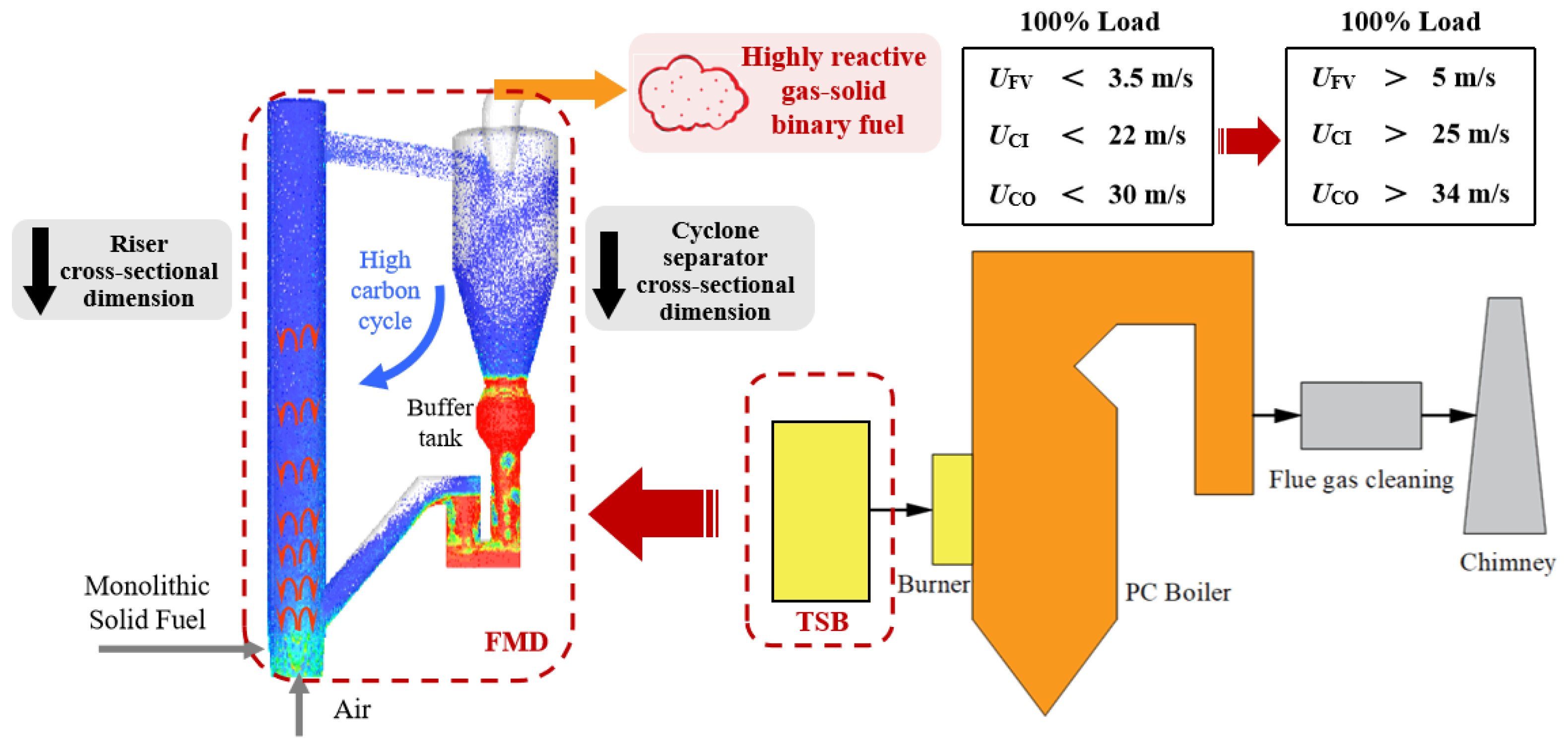
2.1. Experimental Setup

Figure 2 depicts the schematic diagram of the MW-grade pilot-scale test platform for peak shaving utilized in this study. The test platform, designed for a load of 1 MWth (100% load), comprises an FMD, an up-fired combustion chamber (UFC), and auxiliary equipment. Pulverized coal undergoes partial combustion and gasification in the FMD to produce high-temperature gas-solid reactive fuel. Subsequently, this fuel enters the bottom of the UFC, and its combustion path is directed from the bottom to the top.
The FMD consists of a riser, a cyclone separator, and a U-shaped returner, with the body constructed from steel and wrapped externally in insulation rock wool. Both the UFC and FMD are self-sustaining heat devices, maintaining their temperature through the heat released from the pulverized coal, heat absorption by the cooling lances, and heat dissipation to the surrounding environment.
The auxiliary equipment includes a coal feeding system, an air distribution system, and a flue gas treatment system. The air distribution system consists of primary air, secondary air, and burnout air. The primary air is injected from the bottom of the FMD, while the secondary air is introduced from the bottom of the UFC to aid ignition and stabilize combustion, preventing coal dust from settling. The burnout air nozzles are arranged in six layers along the UFC, positioned at distances of 3300 mm, 4100 mm, 5200 mm, 6400 mm, 7960 mm, and 9580 mm, respectively, from the central plane of the high-temperature gas-solid reactive fuel injection, ensuring the efficient and complete combustion of the pulverized coal.

2.2. Experimental Methods and Sampling Ports

There are three temperature measurement points (K-type thermocouples, ±0.5% FS), with their positions being 200 mm, 900 mm and 1750 mm from the bottom of the FMD, respectively. Another two temperature measurement points (K-type thermocouples, ±0.5% FS) are located at the returner and the outlet of the cyclone separator, and pressure taps are set on the temperature measurement tubes of each layer. Since the influence of thermal radiation on the measured temperature was insignificant, the correction for the combustion temperature was not taken into consideration. Additionally, a total of twenty temperature measurement points (S-type thermocouples, ±0.5% FS) are arranged along the UFC in 7 layers, with their positions being 400 mm, 1980 mm, 3180 mm, 4640 mm, 7640 mm, 10,640 mm and 14,500 mm away from the central plane of the high-temperature gas-solid reactive fuel injection.
Sampling is conducted at the outlet of the FMD, encompassing combustible gas and preheated char. The combustible gas is collected using fluorinated membrane gas bags and its composition is measured by Agilent 3000A Micro GC (USA, with a sensitivity < 10–20 ppm), while the NOx concentration in the gas is tested by a KM9106 portable analyzer from Britain, featuring an instrument error < ±5 ppm. The particle size distribution of the raw coal and the preheated char is obtained using a Mastersizer 2000 laser analyzer. Furthermore, specific surface area (SSA, determined by BET theory [25]), total pore volume (TPV, calculated by BJH theory [26]), and average pore diameter (APD) are determined by a Micromeritics ASAP 2460 Analyzer (from the U.S.), and scanning electron microscopy (SEM) is utilized to observe the apparent morphology of the particles. Additionally, the carbon frame structures of raw coal and preheated char are characterized by a LabRAMHR800 laser Raman spectroscopy tester, and the form of nitrogen-containing functional groups is investigated with an X-ray photoelectron spectrometer (XPS, ESCALab 250Xi, ThermoFisher Scientific, Waltham, Massachusetts, USA). The NOx emissions at the tail of the text platform are monitored online using a GASMET DX4000 gas analyzer (Finland, with an instrument error < ±2%), and the O2 concentration is measured online using a testo-350 flue gas analyzer (Germany, with an instrument error < ±5%) and a zirconia oxygen analyzer. Additionally, the concentration of CO in the flue gas is directly related to the combustion efficiency (η) [27], making it a key indicator for assessing that efficiency.

2.3. Fuel Characteristics

In this study, Shenmu bituminous coal (BC) is primarily selected as the experimental fuel due to its excellent fuel property. Simultaneously, to further investigate the fuel adaptability and expand the relevant conclusions, a typical lean coal (LC) produced in Shanxi Province, China is selected as the comparative fuel. The proximate and ultimate values of BC and LC are shown in Table 1. Figure 3 shows the particle size distribution of BC and LC. The particle size range of the two coal types was controlled within 0~0.18 mm through screening to meet the coal fineness requirements of general power stations, and the particle sizes at cumulative volume fractions of 50% (d50) are 78 μm and 74 μm, respectively.

2.4. Experimental Conditions

Experimental conditions are illustrated in Table 2. Cases 1, 2, Cases 3, 4, and Cases 6, 7 were employed to explore the influences of adding a buffer tank on the self-stable operation of FMD and fuel modification efficacy. Additionally, Cases 2, 4, 5 and Cases 7, 8 were adopted to examine the combustion performance and NOx emissions under varying loads. Among them, the load is the experimental load, which was controlled by the coal feeding rate. Eventually, the performance variances between FMD and TSB were investigated.

3. Results and Discussion

3.1. Effects of Buffer Tank on FMD Operation and Fuel Modification

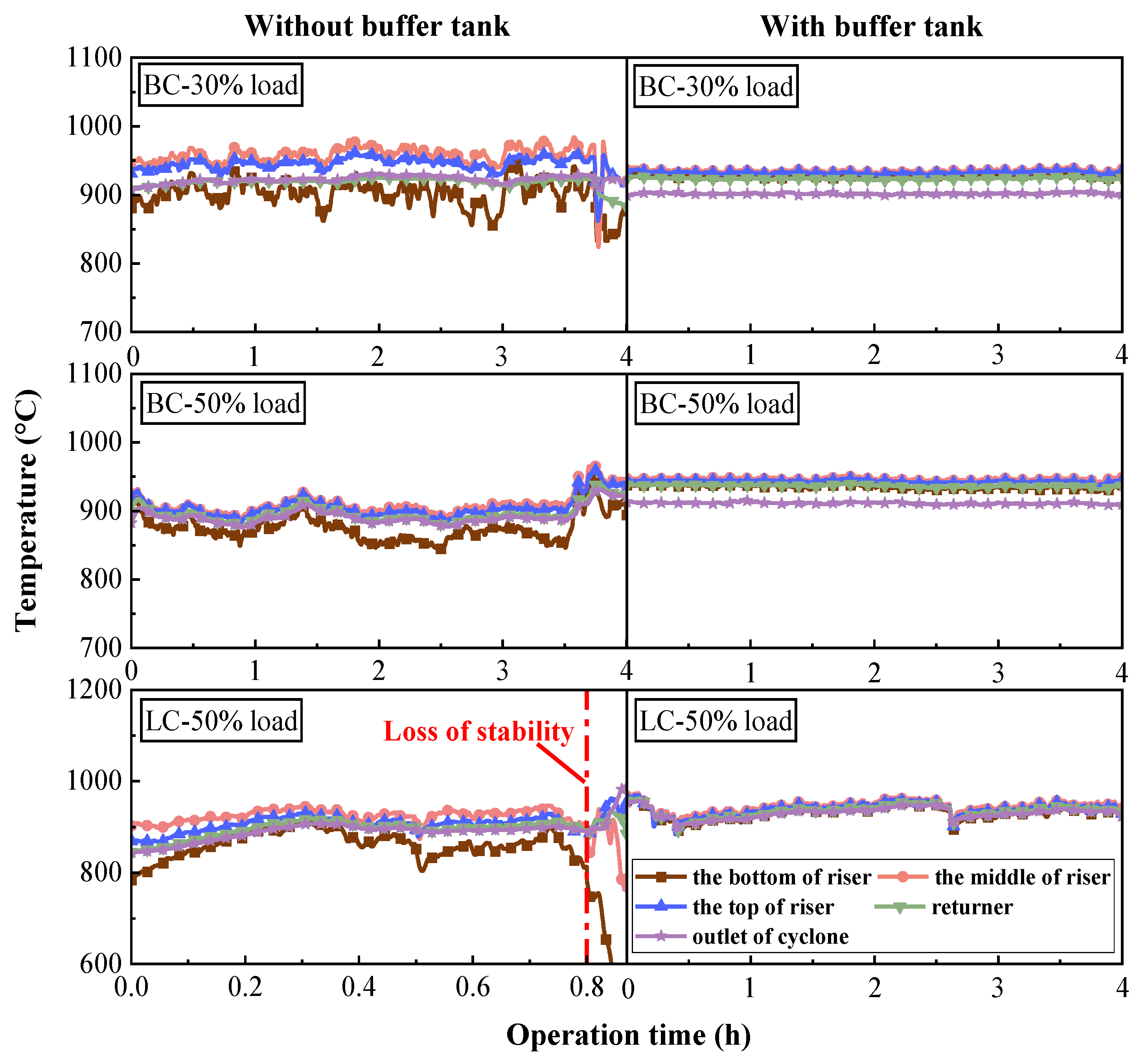
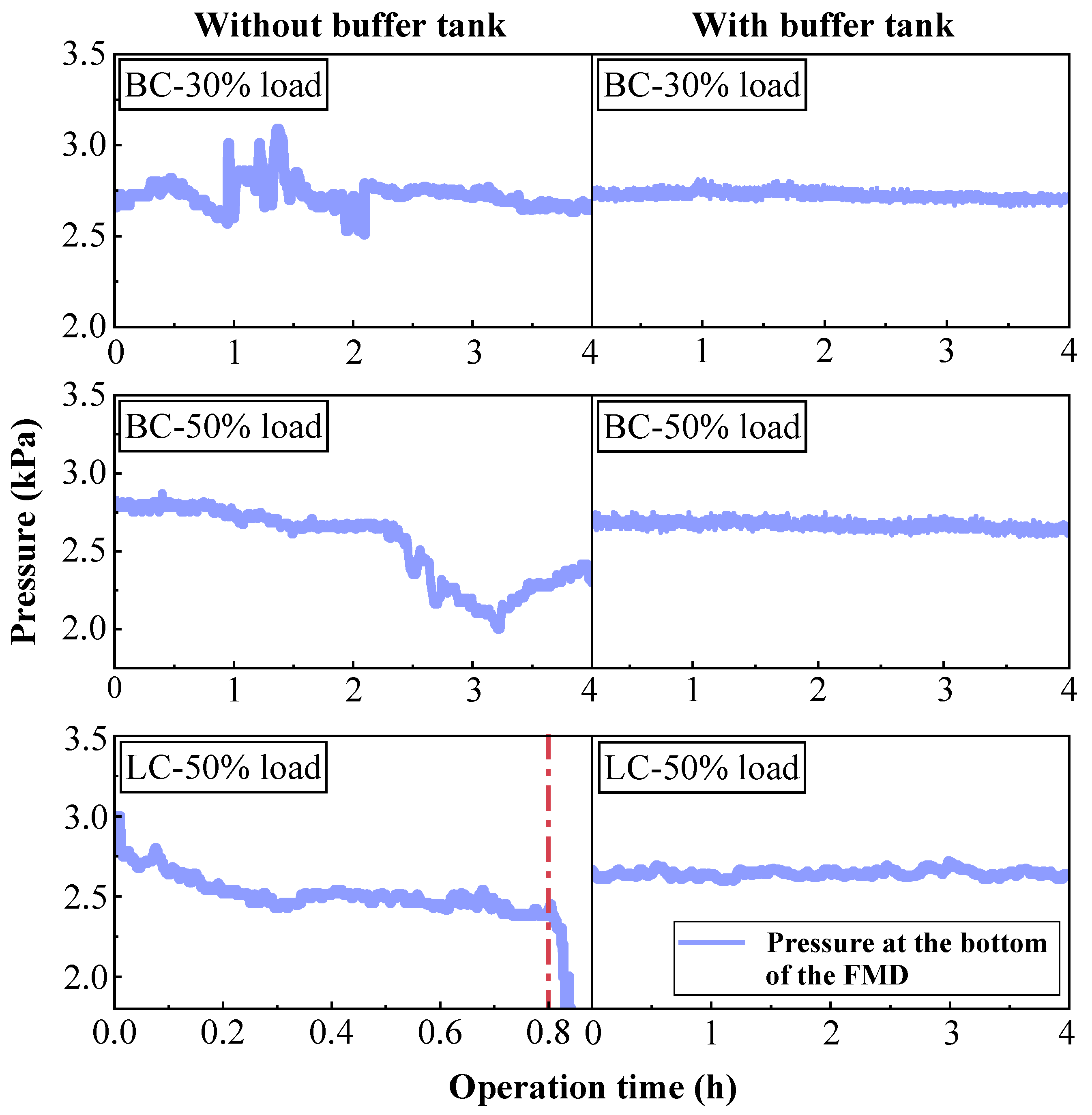
3.1.1. Operation Characteristics of FMD

Figure 4 depicts the temperature distributions of FMD during stable operation time. Compared to the previous experimental results [21], the temperature fluctuations in the FMD are significant. BC, with good combustion characteristics, can generally sustain long-term stable operation, whereas LC cannot, which is related to the structural change of FMD. The reduced cross-sectional dimensions of the riser and cyclone separator leads to the accumulation of pulverized coal and bed material at the bottom of the cyclone separator [28], hindering the establishment of a complete cycle in the FMD and impacting its operational stability. To alleviate the problem, a buffer tank is installed at the riser of the returner. It is obvious that after the installation of the buffer tank, the temperature in the FMD becomes more stable, allowing for prolonged and stable operation. The reason is that the buffer tank provides additional space for the material discharge from the cyclone separator, thereby alleviating material accumulation issues and facilitating the establishment of the FMD cycle. Furthermore, the stability and uniformity of temperature in the FMD are influenced by the circulation rate of pulverized coal [29]. Consequently, due to less reactive combustion characteristics, the interaction between LC and air is weaker, leading to greater temperature fluctuations of the LC in the FMD.
Figure 5 presents the pressure distribution at the bottom of the FMD during stable operation time. For the FMD without a buffer tank, significant reductions in bottom pressure were observed under varying loads during BC combustion. Nevertheless, throughout this operational period, the FMD can maintain continuous operation via self-regulation. Conversely, when combusting LC, there was a drastic decline in bottom pressure, signifying a distinct phenomenon of bed material escape. After approximately 0.8 h of operation, the stability of FMD became impossible to sustain. For the FMD with a buffer tank, whether BC or LC as fuel, the fluctuations in bottom pressure were significantly attenuated, and the continuous operational duration exceeded 4 h, which suggested that incorporating a buffer tank effectively enhances the operational stability of the FMD.

3.1.2. Analysis of Gas Composition During Fuel Modification

Figure 6 shows the principal components and calorific values (CV) of the combustible gas. Obviously, the effective constituents in the FMD outlet gas were CO, H2 and CH4. The main reactions in FMD are shown as (1)–(6).
C H 4 ⇌  C + 2 H 2
C + C O 2 2 C O
C + O 2 2 C O
C + H 2 O C O + H 2
C + O 2 C O 2
C O + H 2 O C O 2 + H 2
The buffer tank could mitigate pressure fluctuations within the system, thereby modifying the reaction process in the FMD. For BC without buffer tank, the return space was comparatively limited, resulting in higher coal gas content within the FMD and material accumulation. This accumulation disrupted intermittent return flow and caused an uneven distribution of materials in the riser. Consequently, this might create localized oxygen-rich zones, making the pulverized coal more susceptible to combustion reactions. Given that the efficiency of combustion reactions was 3 to 4 times greater than that of gasification reactions, it generated localized high temperatures that facilitate the release of volatiles and the progression of reactions (1) to (6). Following the installation of the buffer tank, due to BC’s inherent reactivity, variations in combustible gas content were relatively minor, while LC’s operational characteristics within the FMD were more profoundly impacted.
According to the ash balance hypothesis [30], the calculation results of the conversion ratio of each component during fuel modification are illustrated in Figure 7. For BC, the conversion ratios of H and V were over 90%, illustrating that almost all the volatiles were released in the FMD. By contrast, the conversion ratios of H and V for LC were lower than those for BC, which was related to the higher ash content. More organic components were wrapped inside its ash shell, hindering their release. The conversion ratios of N exceeded 60%, illustrating that most fuel-N was released in the FMD and then tended to be reduced to N2 due to the reducing atmosphere. Hence, higher N conversion ratio greatly reduced the possibility of NOx generation in the subsequent combustion.
Under the conditions in the absence of a buffer tank, for BC, the conversion ratio of C was higher, which was mainly attributed to the presence of the local oxygen-rich zones mentioned previously. These combustion atmospheres in specific zones brought about increased carbon consumption. On the contrary, the conversion ratios of H, N, and V remained relatively unchanged ascribable to the inherent reactivity of BC. Whether a buffer tank existed or not, the gasification reaction rate of BC was high, and the reaction temperature within the FMD was maintained within the optimal range (Figure 4), with a relatively balanced thermal load and stable reaction conditions (Figure 5). For LC, the high ash and low volatile matter content indicated a lower inherent reactivity. Nonetheless, upon integrating the buffer tank, the FMD’s operation attained enhanced stability, enabling a more evenly distributed thermal load and reducing occurrences of excessive pyrolysis and carbonization [31]. This enhancement improved the fluidization state within the FMD, thus increasing the organic component release rates.

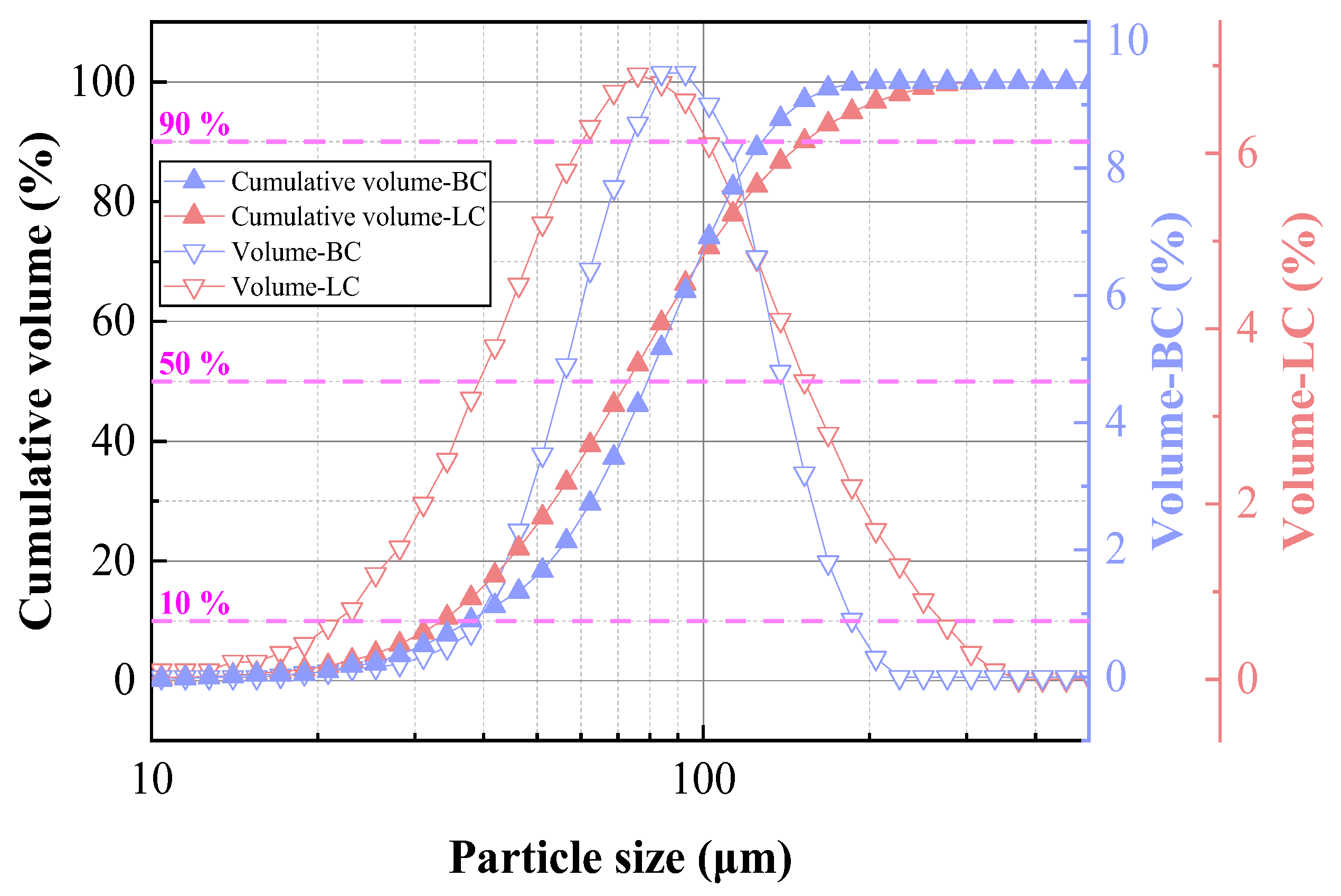
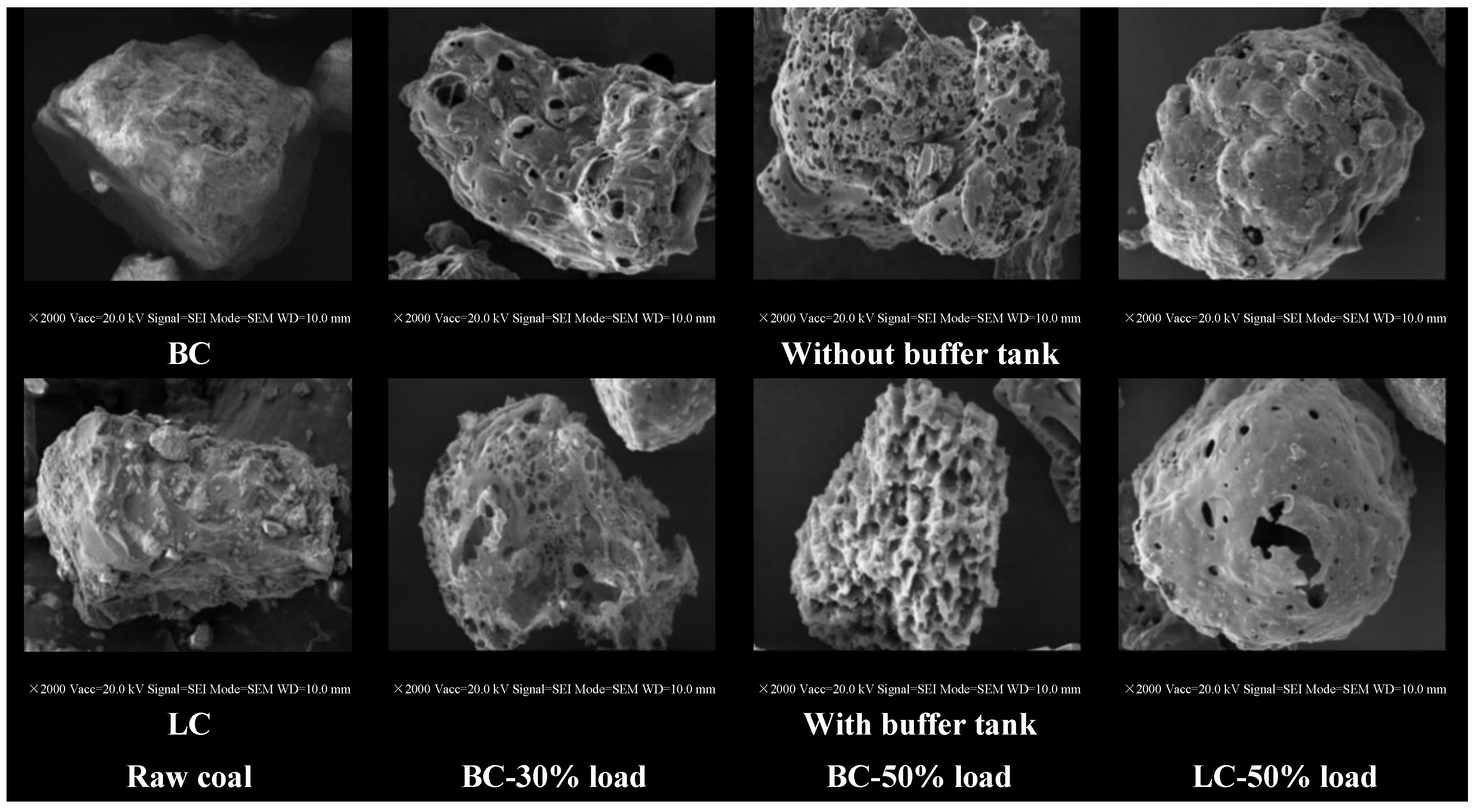
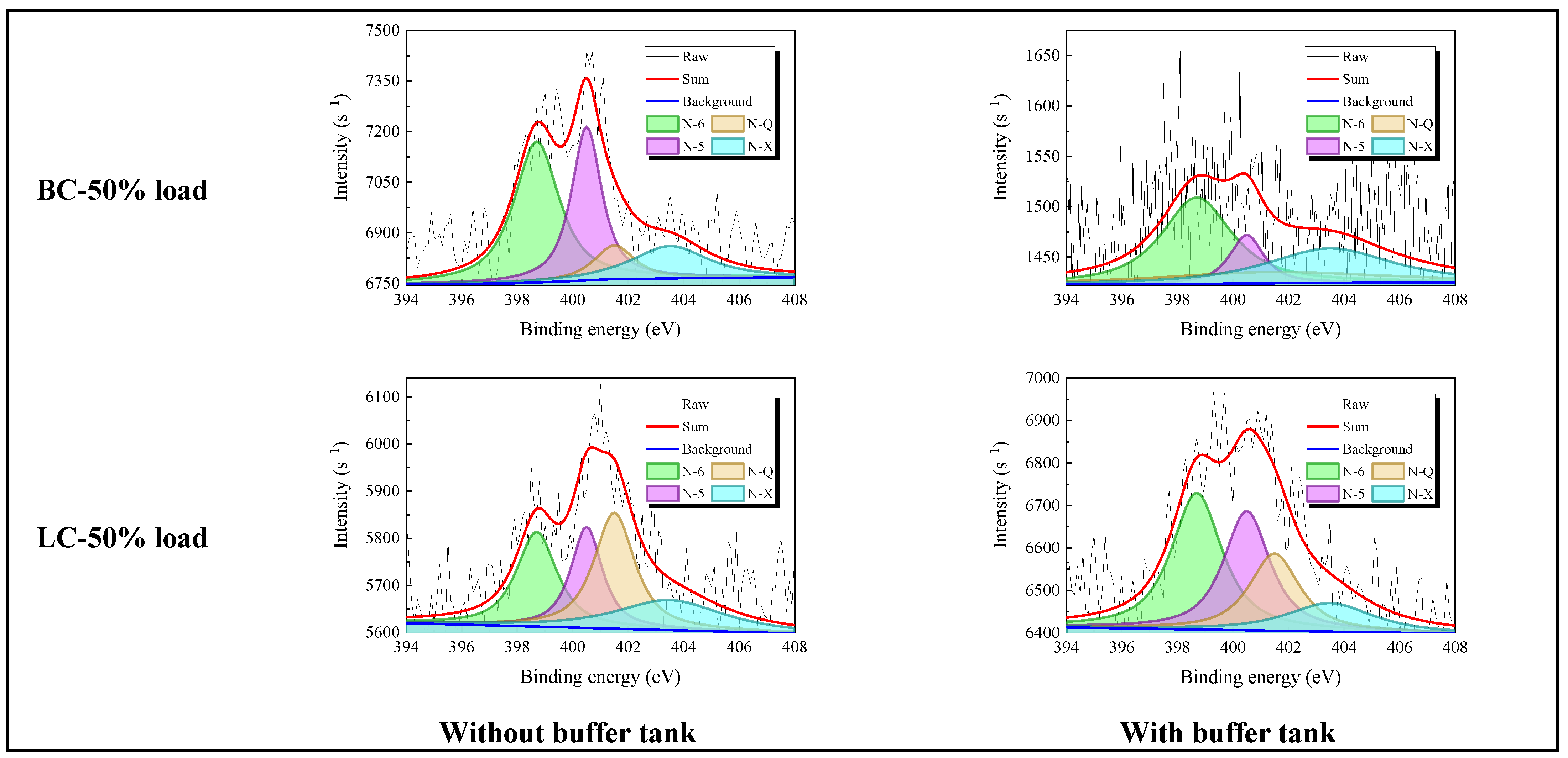
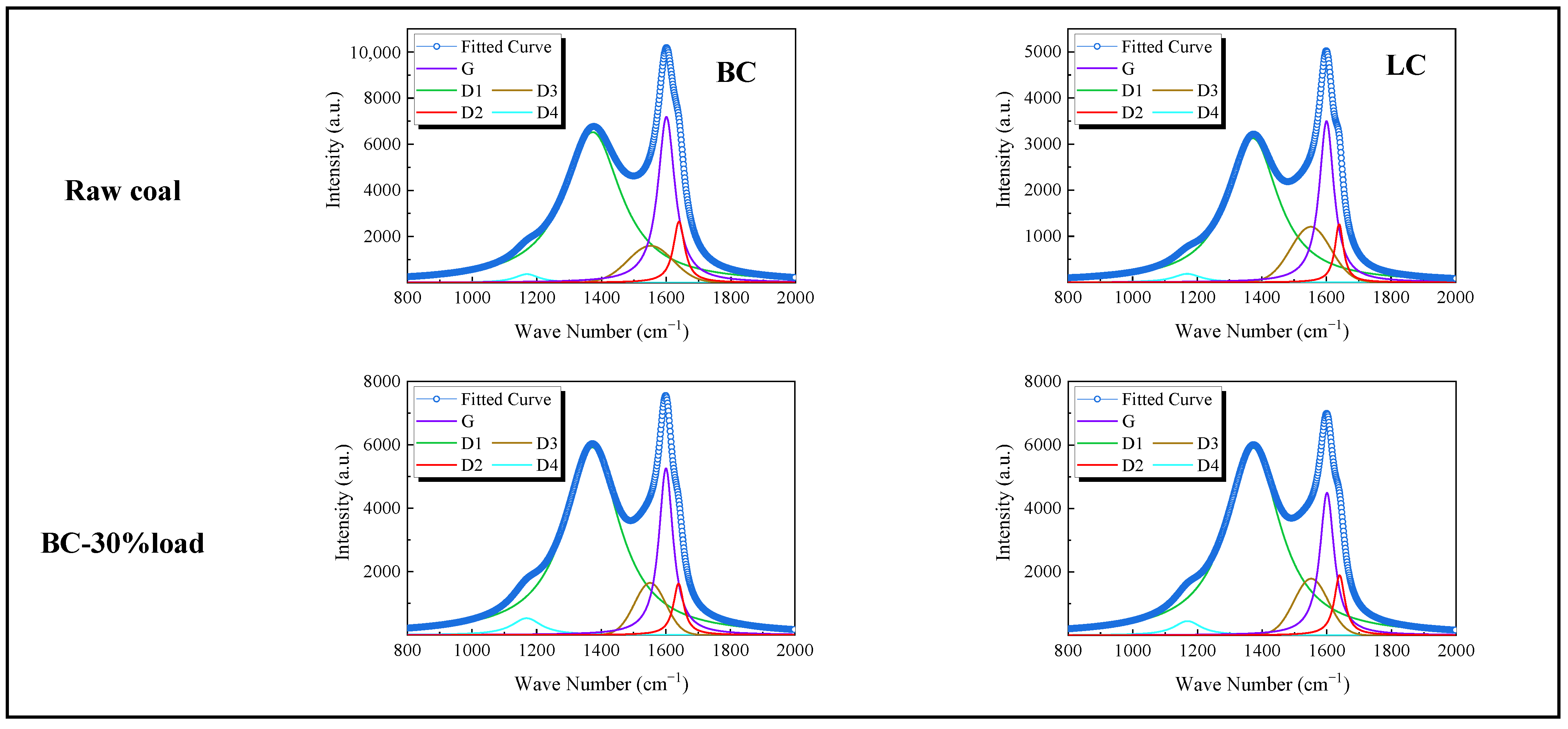
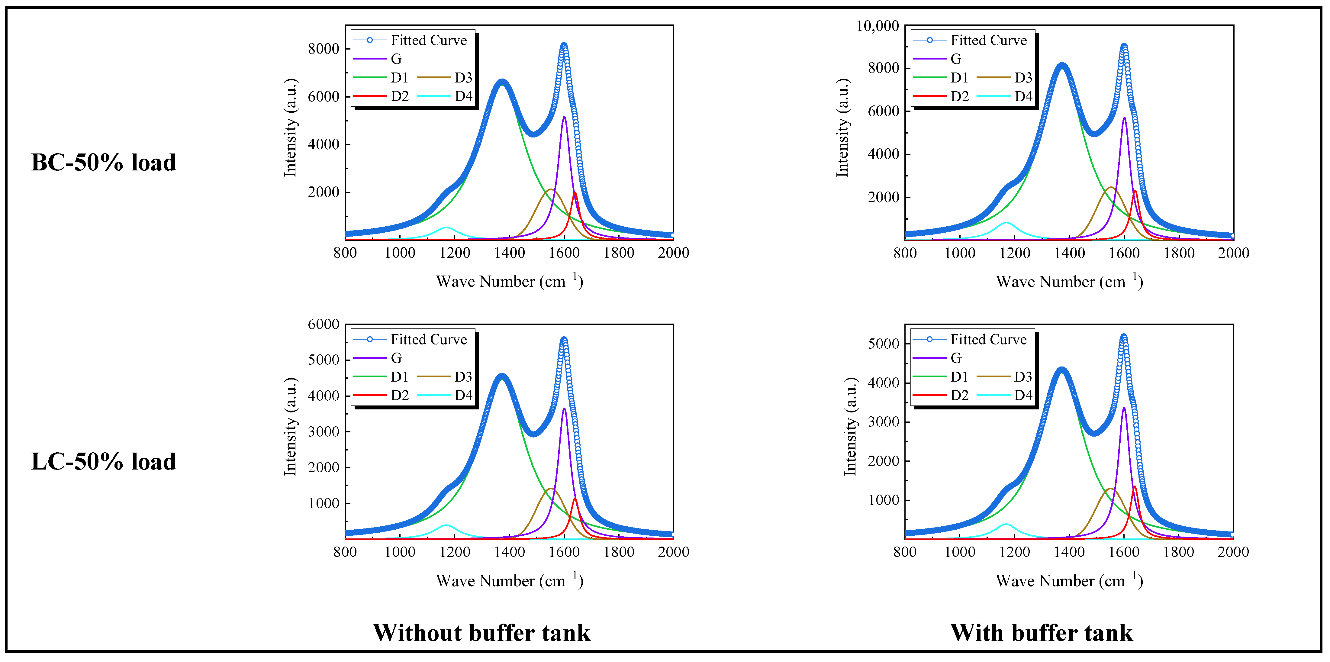
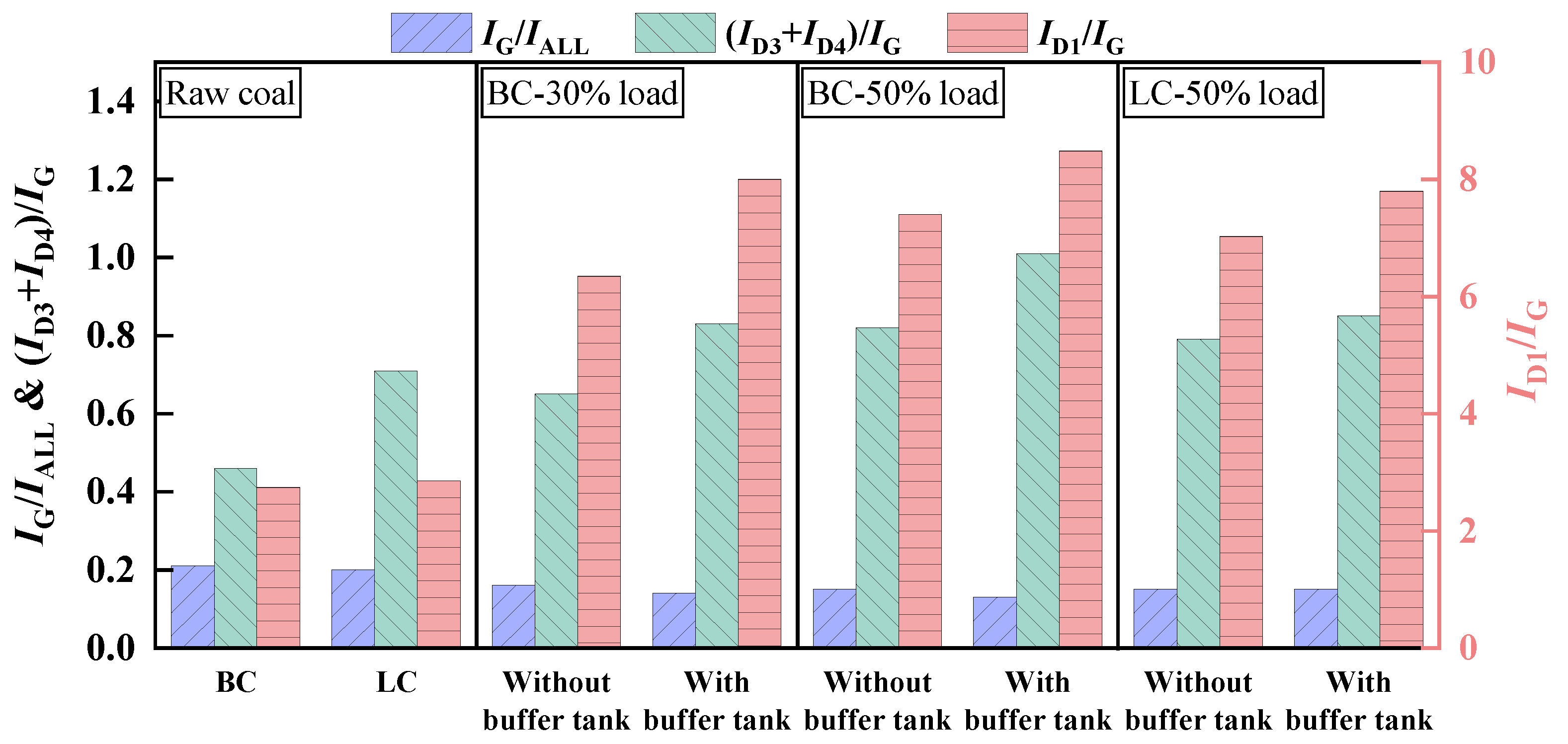
3.1.3. Physicochemical Properties of Preheated Char

Figure 8 depicts the particle size distribution of preheated char and raw coal. For both BC and LC, the particle size of preheated char was significantly smaller compared to that of raw coal. It was notably observed that the particle size of preheated char at 30% load without the buffer tank was larger than that of raw coal. The reason was that the decreased air volume diminished the contact frequency between the primary air and pulverized coal, thereby inhibiting the erosion of carbon skeletons. Furthermore, the cyclic char captured by the cyclone separation was prone to stick in the loop seal without the buffer tank due to the higher H2O content in BC, resulting in a significant increase in the particle size of the preheated char. Following the installation of the buffer tank, a further reduction in the particle size of preheated char was observed, indicating that the buffer tank facilitated a more uniform mixture of gas and solid phases while enhancing fluidization characteristics, thereby promoting stable operation of the FMD. Consequently, the interaction between preheated gas and char became more efficient, leading to a reduction in particle agglomeration and an enhancement in the fragmentation of larger particles.
Figure 9 presents the SSA (specific surface area), TPV (total pore volume) and APD (average pore diameter) of preheated char and raw coal. In comparison to raw coal, the SSA, TPV, and APD of preheated char exhibited significant increases. This enhancement was attributed to the release and partial combustion of volatile substances during fuel modification, which facilitated the formation of micropores and contributed to the collapse of the carbon skeleton in raw coal, indicating a more developed pore structure and a substantial improvement in the physical properties of preheated char. With the installation of the buffer tank, both material circulation and gas-solid separation efficiency were enhanced, which helped prevent aggregation among preheated char particles while increasing their rolling motion and mutual abrasion, thereby giving rise to excellent modification characteristics, which aligned with the conclusions drawn in studies [24], indicating a negative correlation between particle size and SSA (Figure 8). Additionally, the buffer tank contributed to a more uniform internal temperature within the FMD. Given the high sensitivity of volatiles to temperature [32], this uniformity facilitated the formation of additional pores and cracks on char particle surfaces, consequently enhancing their TPV and APD. Notably, the TPV of LC’s preheated char decreased following the installation of the buffer tank, which could be attributed to LC’s lower volatile matter content relative to BC. However, the SSA increased, indicating that the buffer tank could significantly enhance the development of a porous and loose structure during fuel modification for coals with a high volatile matter content, while effectively promoting an increase in fine particles for coals with low volatile matter content.
Figure 10 shows the apparent morphology analysis of preheated char and raw coal. Both BC and LC exhibited a smooth surface and dense texture. In contrast, bubbly or honeycomb-like micropores were distributed throughout the preheated char. This formation occurred as the pulverized coal particles underwent thermal stress during the fuel fluidization process within the FMD, leading to further breakdown of larger particles. Concurrently, the release of volatile substances along with partial gasification and combustion reactions contributed to the development of micropores and cracks [33]. Additionally, following the installation of the buffer tank, both the quantity and size of pores on particle surfaces increased (Figure 9). This enhancement could be attributed to more stable material circulation and uniform temperature achieved within the FMD (Figure 4), which facilitated a greater release of volatile substances (Figure 7). Furthermore, while uniform temperature reduced thermal stress on particles, decreased particle size coupled with an increase in SSA resulted in heightened thermal stress [34].
The fitting results of XPS-N1s spectrum of preheated char and raw coal are illustrated in Figure 11. According to the results of XPS, Pels [35] classified the existent morphology of N functional groups into N-5, N-6, N-Q and N-X. The relative content of nitrogen-containing functional groups was defined as the ratio of the area corresponding to these groups to the total area under the XPS-N 1s spectral curve. Consequently, the relative content of nitrogen functional groups in raw coal and preheated char can be determined by integrating the area beneath this curve [20].
Figure 12 depicts the relative content of N functional groups in preheated char and raw coal. The levels of N-5 and N-6 in raw coal were relatively high, with their combined proportion exceeding 70%, indicating that N atoms were predominantly located at the periphery of organic aromatic structures [36]. At a load of 30%, the relative content of N-Q without a buffer tank was significantly higher than that with it, correlating with difference in particle fluidization characteristics. In the presence of the buffer tank, recycled char particles captured by the cyclone separator tended to disperse more extensively, facilitating chemical erosion of the carbon structure. Consequently, N atoms at the center of aromatic structures were more likely to migrate towards the edges through cracking, leading to substantial consumption and conversion of N-Q. The relative content of N functional groups in preheated char at 50% load differed from that at 30%. Specifically, without the buffer tank, the relative content of N-5 and N-6 were significantly higher than those with it. This variation arose because increasing the load from 30% to 50% augmented circulating char amounts, resulting in more frequent interactions between char particles and enhancing likelihood without a buffer tank. Although the conversion of N-Q remained inhibited without the buffer tank, the conversion of N-5 and N-6 was similarly constrained due to poor fluidization conditions. Additionally, raw coal contained relatively high levels of N-5 and N-6, indicating that these compounds were better preserved in preheated char. Conversely, when the buffer tank was present, significant conversion occurs for N-5 and N-6 into gaseous components like HCN and NH3, which resulted in higher relative contents of both N-Q and N-X compared to the scenario lacking a buffer tank.
Figure 13 presents the Raman spectrum intensity and peak fitting of preheated char and raw coal, with the laser scanning range configured as 800~2000 cm−1, which encompassed one Gaussian peak (D3 band) and four Lorentzian peaks: G band, D1 band, D2 band, and D4 bond. The relative area ratios of Raman spectral bands (IG/IAll, ID1/IG, (ID3 + ID4)/IG) served as indicators for analyzing changes in the carbon microcrystalline structure [37]. Figure 14 shows Raman analysis of preheated char and raw coal.
Compared to raw coal, the IG/IAll ratio of preheated char decreased, while the ID1/IG and (ID3 + ID4)/IG ratios increased, which aligned with previous results [19,30], suggesting that FMD could effectively enhance the microstructure characteristics of carbon. Notably, following the installation of the buffer tank, a decrease in the IG/IAll was observed alongside an increase in both ID1/IG and (ID3 + ID4)/IG ratios, which indicated that the buffer tank plays a significant role in reducing the degree of graphitization in preheated char while increasing the proportion of active defect carbon structures. The underlying mechanism involves expansion of radial space within the buffer tank, facilitating interactions between preheated char particles and gas components (particularly O2), leading to fractures in carbon rings within aromatic structures. Additionally, the buffer tank made the internal temperature of FMD more homogeneous and improved the pore structure of preheated char particles, increasing SSA and reducing the particle size (Figure 8 and Figure 9), which promoted the destruction of carbon bonds by O2 [38]. Through these combined effects, the buffer tank fostered the transformation from the stable graphite structure to a disordered and active defect structure, thereby enhancing the reactivity of preheated char.

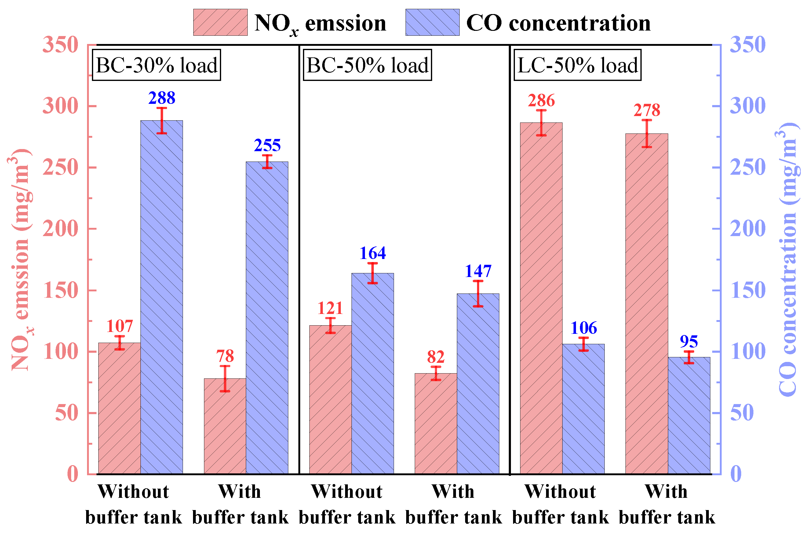
3.1.4. NOx and CO Emission

Figure 15 illustrates NOx and CO emission, and all data have been converted to the standard value at 6% oxygen concentration (@6% O2). Following the installation of the buffer tank, a significant reduction in CO concentration was observed, illustrating a decrement in the incomplete combustion of preheated char. This reinforcement was ascribable to the augmented reactivity of BC and LC resulting from fuel modification. Throughout the initial phase of combustion, the increase in CO concentration effectively intensified the homogeneous reduction reactions involving NOx (Figure 6). With the introduction of burnout air, char-N was released and partially engaged in heterogeneous reduction reactions on its surface. Thus, a well-defined reduction zone and burnout zone could be established within the combustion reaction area. As noted in the previous analysis (Figure 9 and Figure 14), demonstrated that the buffer tank increased both active site density and SSA of preheated char, facilitating O2 diffusion within it while enhancing its combustion reactivity in the UFC, which also provided additional opportunities for reductions of NOx. Furthermore, during fuel modification processes, an increased N conversion ratio suggested that more fuel-N was extracted from FMD and reduced to N2 (Figure 7). As a result, there was a decrease in fuel-N entering UFC, thereby diminishing its potential transformation into NOx.

3.2. Research on Peak Shaving in Self-Preheating Combustion Under Varied FMD Loads

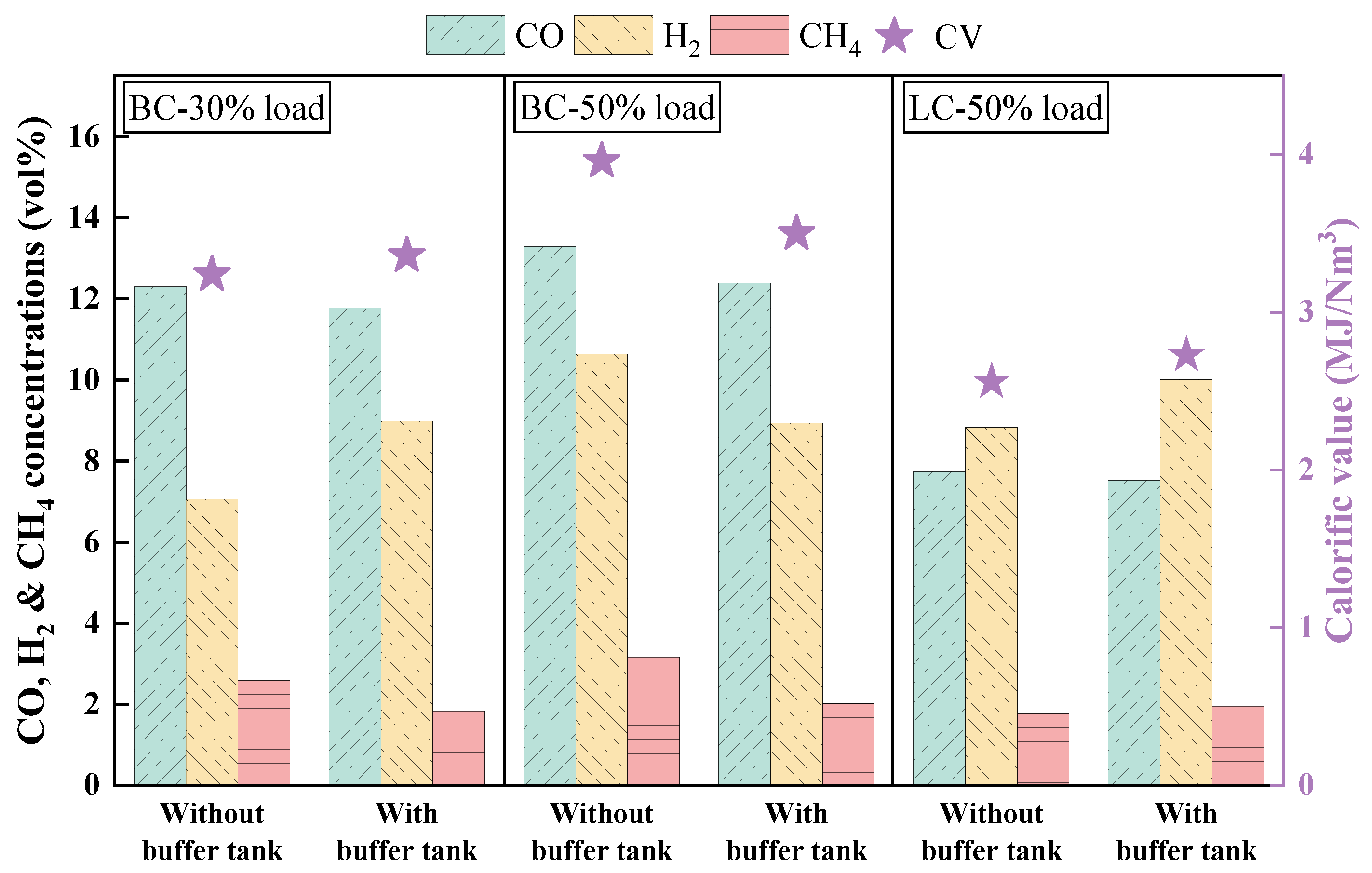
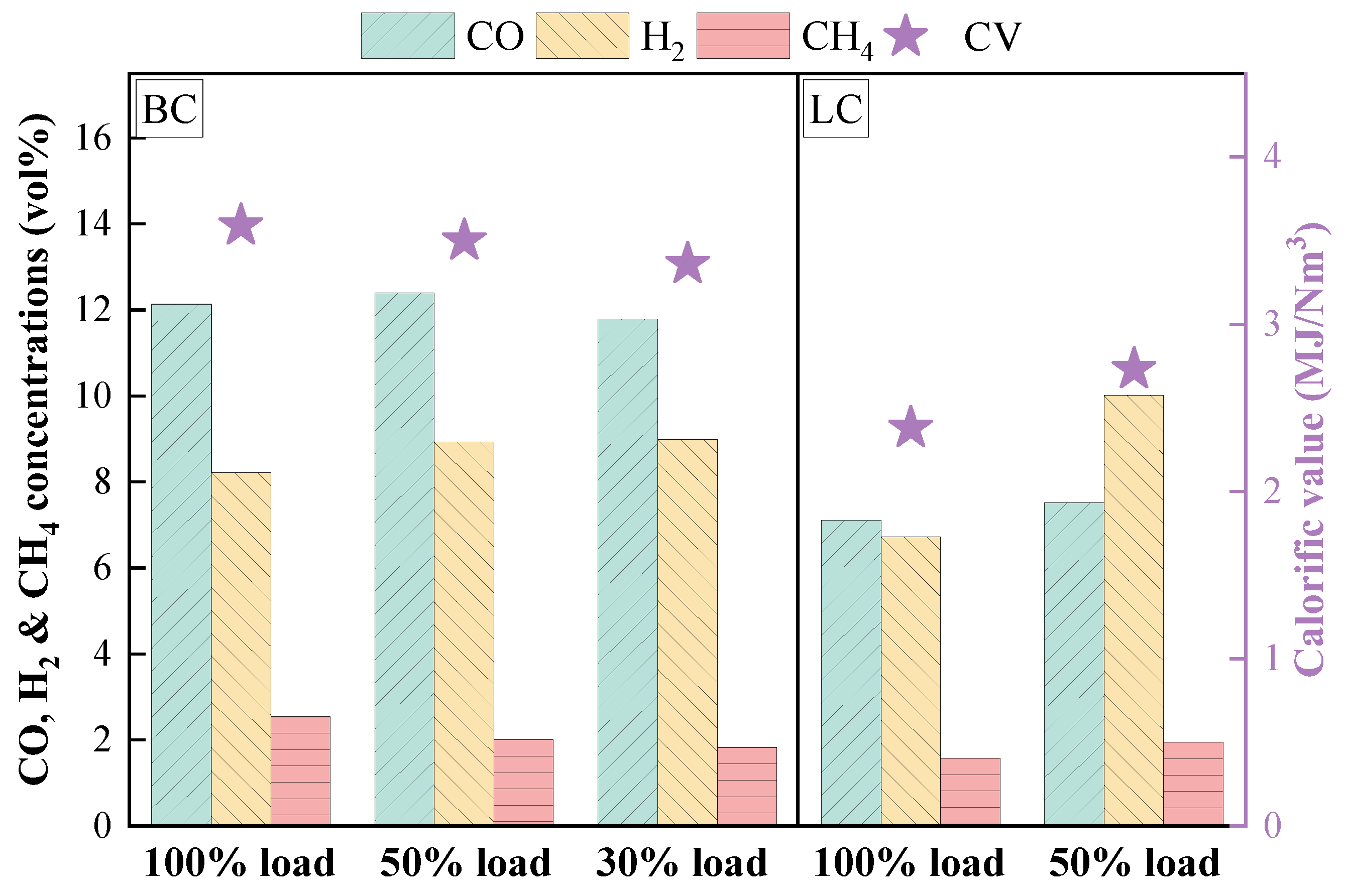
3.2.1. Analysis of Gas Composition During Modification

Figure 16 depicts principal components and CVs of combustible gas. For both BC and LC, when the load was decreased from 100% to 50%, the contents of H2 and CO increased, while that of CH4 diminished. This change occurred because, at a lower load, both the coal feed rate and primary air volume were reduced, leading to an extended residence time which facilitated the release of volatiles and enhanced gasification reactions [39]. Given that volatile matter constituted the primary source of CH4, reactions (1) and (3) were enhanced, resulting in a decrease in CH4 content alongside an increase in CO and H2. Notably, for LC, CH4 content exhibited an increase when the load was reduced. This phenomenon correlated with a reduction in FMD temperature. As reaction (1) was endothermic, a reduction in load inhibited this reaction, leading to a slight increase in CH4 content due to the combined effects of both factors. Furthermore, the CV of CH4 was significantly higher than that of H2 and CO, consequently, variations in CV aligned harmoniously with changes observed in CH4 content. As the load was further diminished to 30%, there was a significant reduction in the primary air volume and the spatial density of the fuel, which led to a considerable decline in the effective contact rate between the fuel and O2. This phenomenon further inhibited reactions (3) and (5), culminating in a reduction of CO and CO2 content.
Figure 17 presents conversion ratio of each component during fuel modification. For BC, when the load is reduced from 100% to 50%, the extended residence time of the fuel and the more uniform temperature distribution facilitated gasification reactions and consequently leading to an enhanced conversion ratio. While for LC, when the load was diminished, the FMD temperature experienced a significant decline. This occurrence attenuated the rate of partial gasification and combustion reactions while simultaneously inhibiting the release of volatiles, resulting in a substantial decrease in the C conversion ratio. Furthermore, the reduction in the H conversion ratio is intricately associated with the inhibition of volatile release, as numerous alkane structures present within the volatiles encompass considerable quantities of H. When the load is further diminished to 30%, the effective contact rate between O2 and pulverized coal markedly declines, leading to a corresponding reduction in the C conversion ratio. For BC, judiciously reducing the load to enhance the residence time of fuel within the FMD proved advantageous for facilitating the conversion of fuel-N to N2. Conversely, for LC, a measured increase in load that promoted particle collisions and fragmentation was beneficial for optimizing the release of fuel-N.

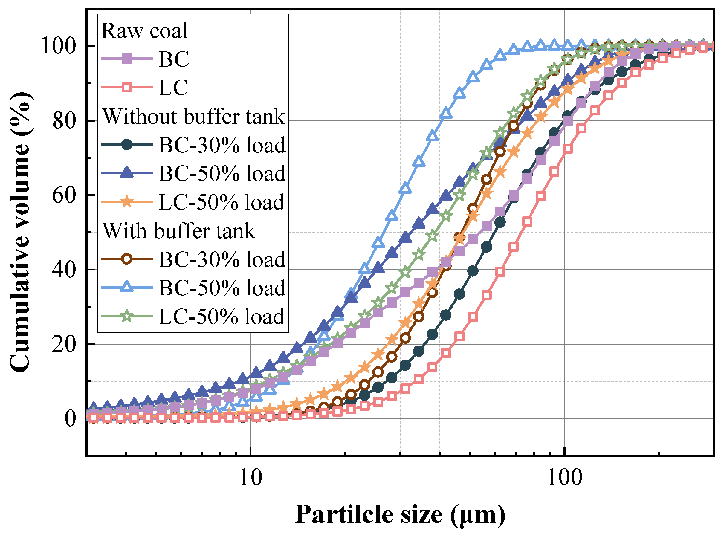
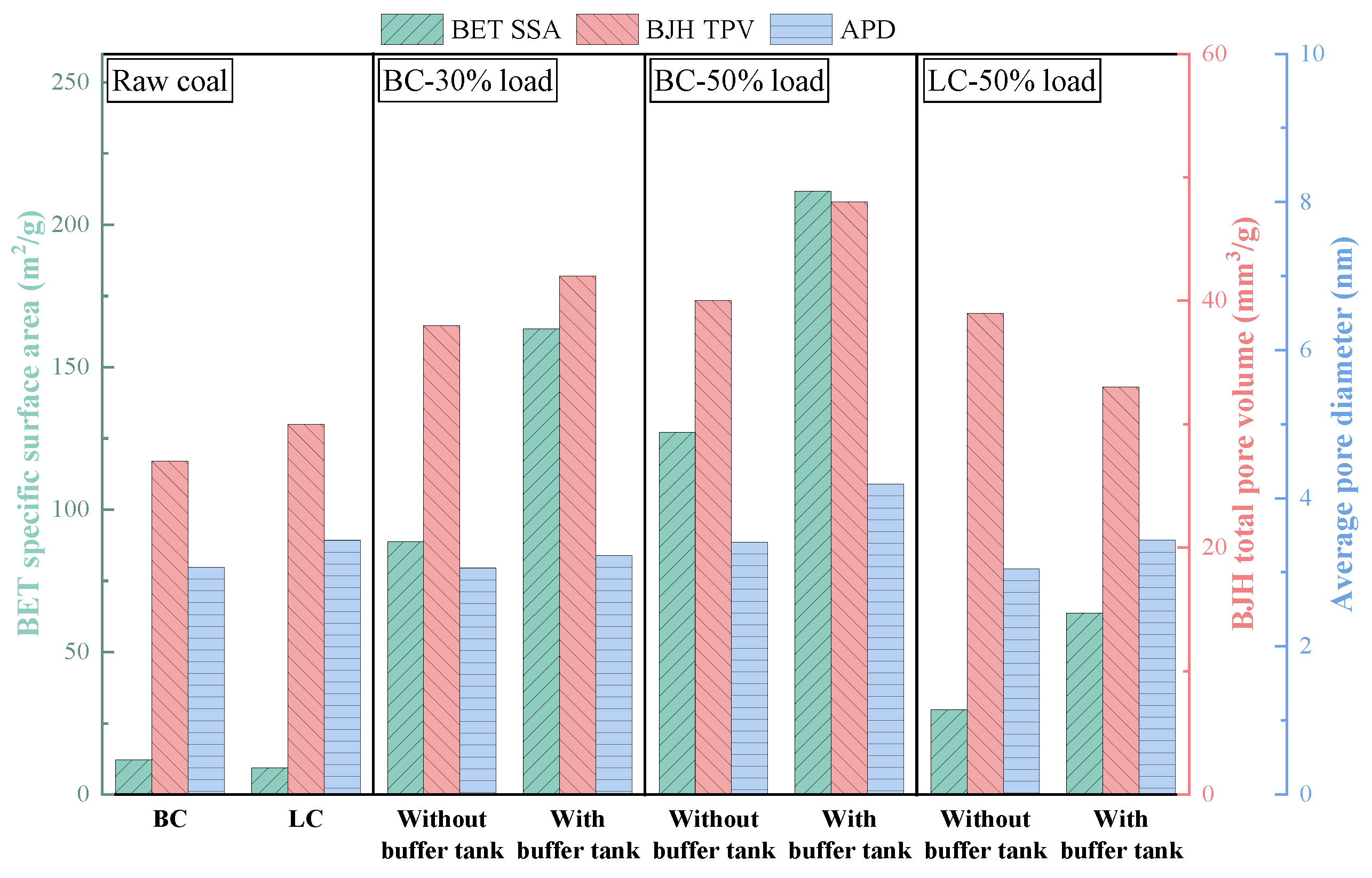
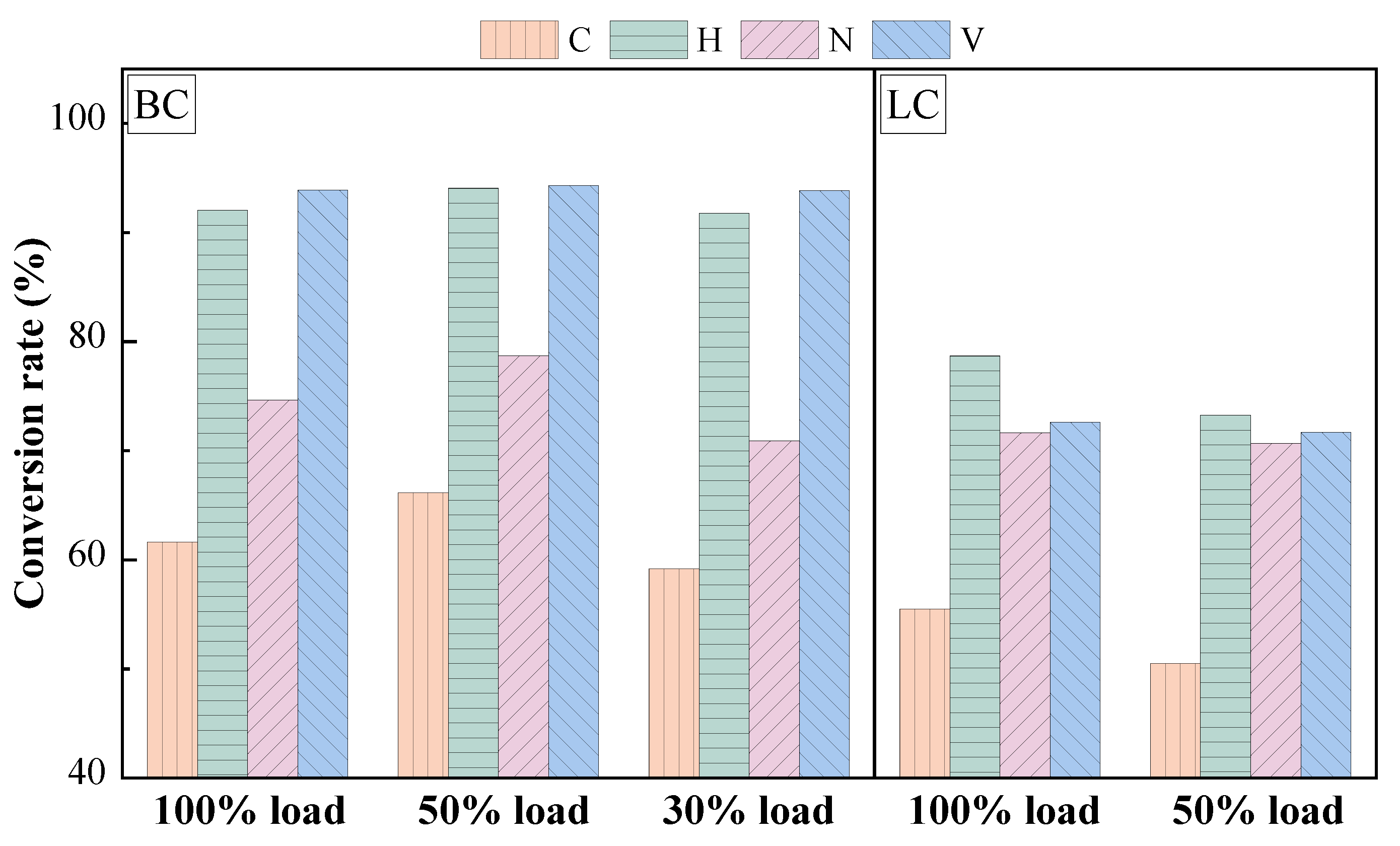
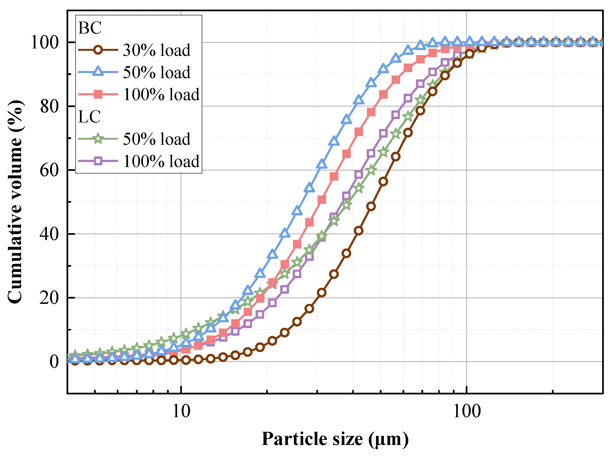
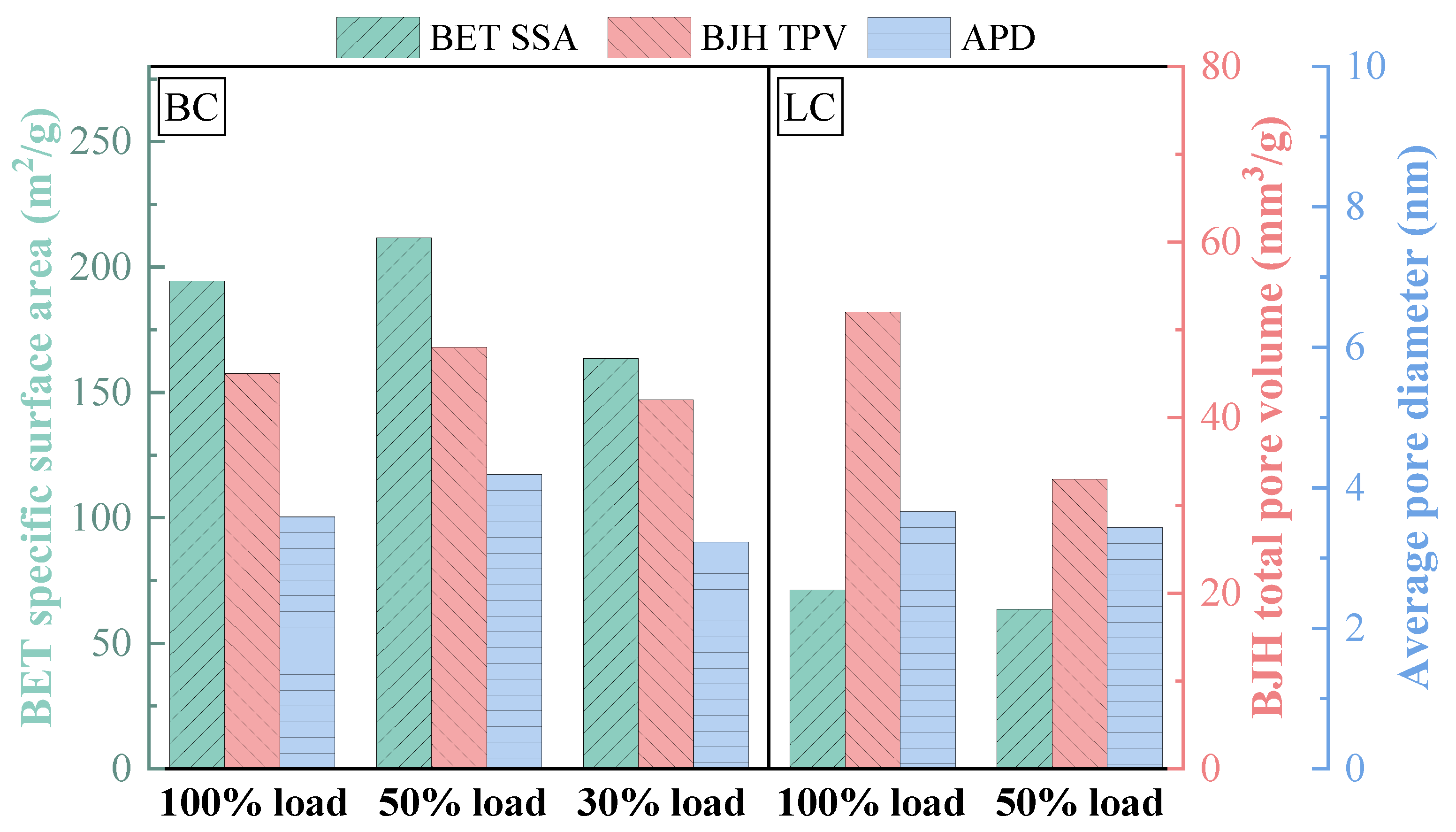
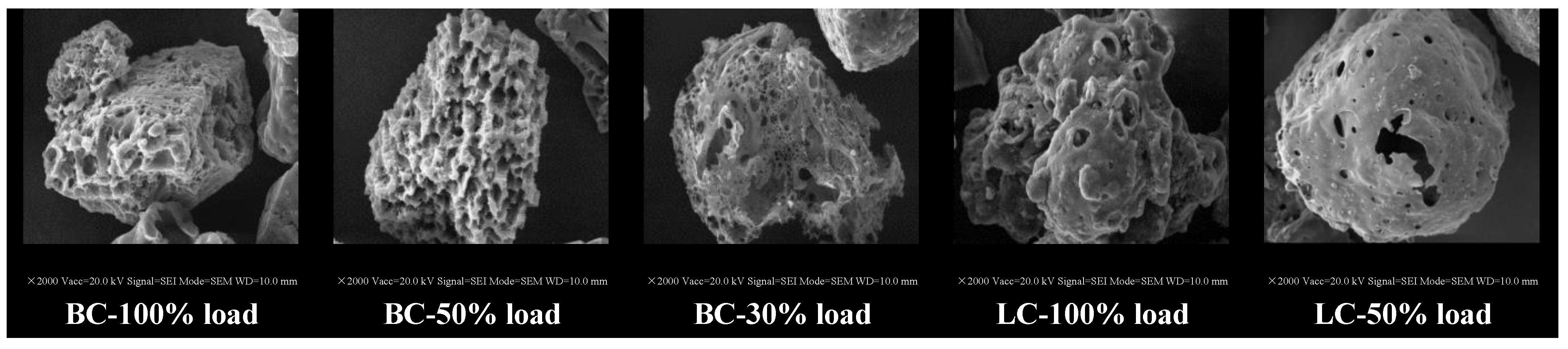
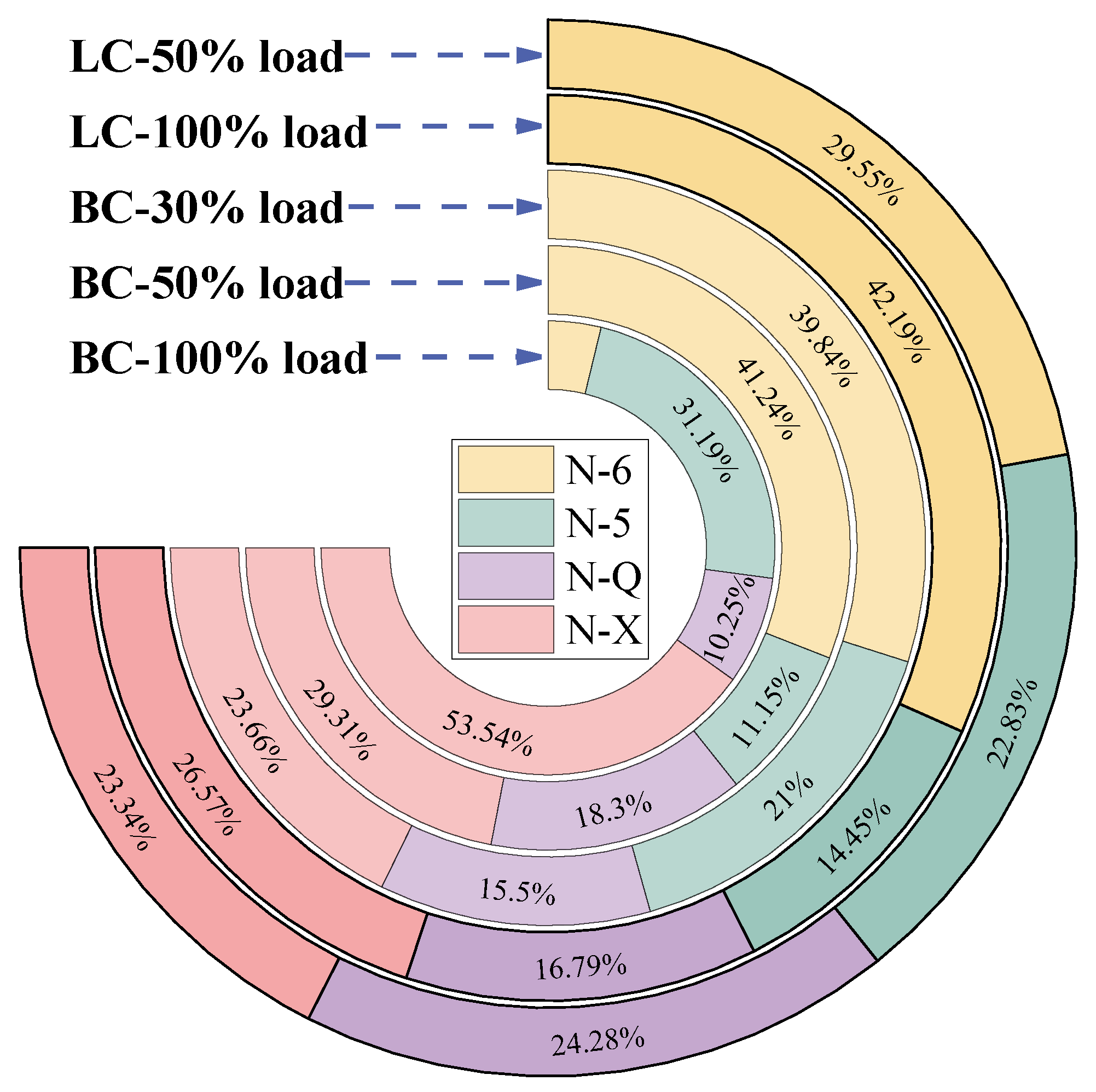
3.2.2. Physicochemical Properties of Preheated Char

Figure 18 shows the particle size distribution of preheated char at different loads. For BC, the particle size of preheated char reached its minimum at 50% load. At 100% load, the heightened UFV significantly reduced particle residence time, detrimentally impacting cyclone separator efficiency at elevated cycle rates and resulting in the escape of larger particles. Additionally, at 30% load, the diminished frequency of particle collisions and the comparatively lower reaction rate culminated in larger particle sizes than those observed at a 50% load. In contrast, for LC, the particle size of preheated char at 100% load was marginally smaller than that at 50% load, as the increased FMD temperature enhanced combustion and gasification reactions on the surface of pulverized coal (Figure 4), thereby accelerating both large particle disintegration and small particle consumption.
Figure 19 illustrates the SSA, TPV and APD of preheated char at different loads. For BC, at 50% load, SSA, TPV, and APD of preheated char attained their zenith, signifying a more developed pore structure associated with collisions among pulverized coal particles, thermochemical reactions within the riser, and the disturbance of gas to pulverized coal particles [23]. As illustrated in Figure 15, the fluidization characteristics in the FMD were optimal at 50% load, leading to the strongest interaction between gas components and char particles. The uniform FMD temperature cultivated favorable conditions for gasification reactions, thereby enhancing pore formation both internally and on the surface of pulverized coal particles. Furthermore, the smallest particle size at this load contributed to the maximum observed SSA. In contrast, for LC, SSA, TPV, and APD of preheated char escalated with increasing load. Unlike BC, the FMD temperature for LC rose with increasing load, which enhanced collisions and gasification reactions between particles, thus significantly refining pore structure at elevated loads.
Figure 20 depicts the apparent morphology analysis of preheated char at different loads. For BC, at 50% load, the formation of micropores on the surface of preheated char was enhanced due to stable material circulation and uniform FMD temperature promoting volatile release (Figure 17). In contrast, for LC, the pore structure of preheated char at 100% load was superior, attributed to high primary air volume and heating rate that increased thermal stress on pulverized coal particles. Additionally, the small particle size and large SSA of preheated char further amplify this thermal stress effect (Figure 18 and Figure 19). Consequently, the pore structure of preheated char improved significantly, with BC and LC achieving optimal enhancements in particle pore structure at 50% and 100% loads, respectively.
Figure 21 presents the relative content of N functional groups in preheated char at different loads. At 100% load for BC, the increased primary air volume and UFV led to a higher concentration of O radicals. As previously analyzed, the increased SSA and improved pore structure of preheated char facilitated the combination of O and N-6, resulting in the formation of N=O bonds and promoting N-X creation (Figure 12). Consequently, the content of N-X reached its peak, while the content of N-6 was at its lowest. When the load decreased to 50%, the extended particle residence time allowed for greater cleavage of C-C and C=C bonds. In this scenario, both O within N-X and environmental O participated in oxidizing C atoms. As the N-O bond broke, N-X was converted to N-5. Due to its high reactivity, N-5 tended to convert into volatile compounds and reverted back to N-6 at elevated temperatures. Simultaneously, reduced O atom content inhibited conversion from N-6 to N-X, increasing relative content of N-6. Additionally, nitrogen-containing aromatic heterocycles were prone to polymerization, causing nitrogen groups at char edges to condense into interiors forming more stable forms like N-Q, which also explained increased relative content of N-Q in LC during load reduction. Further reducing load to 30% continued promoting conversion from N-X to N-5 due to the uniform FMD temperature. However, decreased primary air volume and O content inhibit conversion from N-6 to N-X, resulting in an increase in relative content of N-6. Some studies suggest that when temperature exceeds 700 °C with O atoms present, N-6 reactivity increases, fostering its conversion to N-5 [40]. Thus, the combined influence of these factors keeps the relative content of N-6 relatively stable.
The Raman analysis of preheated char at different loads is shown in Figure 22. For BC, at 50% load, the number of active sites was maximized on the surface of preheated char particles, while the degree of graphitization decreased. At 100% load, a larger primary air volume shortened particle residence time. Conversely, at 30% load, a smaller primary air volume reduced the effective contact rate between O2 and particles. Both scenarios diminished the destructive effect of O2 on carbon ring structures, which corresponded with the observed SSA of preheated char and C conversion ratio (Figure 17 and Figure 19). Furthermore, when the load dropped to 30%, a significant decrease in (ID3 + ID4)/IG indicated that O2 content played a more critical role in enhancing carbon microstructure than particle residence time. For LC, reducing the load increased IG/IAll while both ID1/IG and (ID3 + ID4)/IG decreased, suggesting an increase in graphitization degree for preheated char alongside fewer active sites on particle surfaces and reduced defective carbon structure. This change could result from lower FMD temperatures at reduced loads that slowed gaseous reactant diffusion during fuel modification. Additionally, decreased O2 content at lower loads lessened its destructive impact on carbon bonds within aromatic layers.

3.2.3. NOx and CO Emission

NOx and CO emission at different loads are illustrated in Figure 23. For BC, CO content gradually decreased as the load increased, signifying a reinforcement in η. This trend was associated with the elevated amount of the high-temperature gas-solid reactive fuel and augmented combustion temperatures in the UFC. In particular, the CO content at 50% load was similar to that at 100% load attributable to the fact that fuel achieved optimal modification efficacy at this level. At this load, SSA, TPV, and APD of preheated char were maximized (Figure 19), reducing O2 diffusion resistance into particles and further reinforcing η. For this reason, incomplete combustion was alleviated to a certain degree. In contrast, ascribable to the inherent properties of LC combustion, which make it less prone to fluctuations from load variations, the CO concentration in the flue gas from LC combustion remained constant across varying loads. For BC, NOx emissions diminished with the load reduction on account of heightened CO levels, and the reducing atmosphere created by CO inhibited NOx formation [40]. Concurrently, a heightened degree of modification fortified the heterogeneous reduction process for NOx. Thus, appropriately lowering the load helped reduce NOx emissions but at the expense of η. Conversely for LC, NOx emissions increased when loads were reduced because lower loads also decreased N conversion ratio during fuel modification (Figure 17), resulting in more fuel-N converting to NOx in the UFC. Meanwhile, the decrease in the degree of modification restricted the reduction capacity of NOx.

3.3. Comparative Analysis of the FMD and TSB Performance

To substantiate the advantages of FMD in terms of fuel modification and NOx emission reduction, a comparative analysis was conducted between FMD and TSB. The operational data for TSB were acquired from previous research [41]. Utilizing BC as the experimental fuel, loads were selected at 30% and 50%, while ensuring uniform air distribution across all operating scenarios. In addition, based on the advantages mentioned of the buffer tank, the FMD referenced in this section was equipped with a buffer tank.

3.3.1. Operational Characteristics of FMD and TSB

Figure 24 depicts temperature and pressure distributions of FMD and TSB. Throughout the continuous operation phase, the temperatures and pressure differentials across various loads exhibited stable fluctuations, which substantiated significant operational stability of FMD and TSB. Notably, TSB incorporated a water-cooling lance with heat absorption nearly invariant within its structure. As the load was reduced from 50% to 30%, the proportion of fixed heat absorption by the cooling lance relative to the total heat released during coal reactions in TSB increased correspondingly, resulting in a lower apparent temperature ranging from 680 °C to 800 °C. In contrast, FMD lacked an internal cooling lance, and at equivalent loads, it featured a more compact volume and enhanced flow parameters that promote thorough mixing between particles and gases. This improvement augmented both heat and mass transfer efficiency, leading to elevated temperatures compared to TSB, specifically within a range of 850 °C to 960 °C. Furthermore, variations in load exerted a more pronounced influence on TSB’s temperature profile, indicating that FMD effectively mitigated substantial temperature discrepancies arising from load fluctuations. Consequently, it could be inferred that BC would manifest distinctly different effects under these two fuel modification atmospheres.

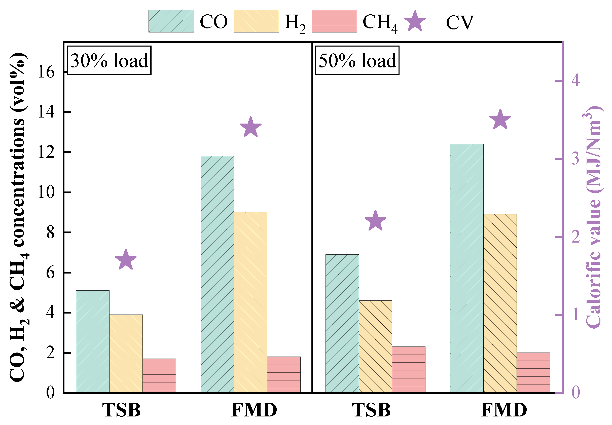
3.3.2. Analysis of Gas Composition During Fuel Modification

Figure 25 presents principal components and CVs of combustible gas. For FMD, under identical loads, both the concentration of combustible gases and the CV surpassed those observed in TSB. Notably, the levels of CO and H2 were even more pronounced, indicating the higher gasification reaction intensity and reducing capability in FMD, which could be attributed to the scale of FMD. A smaller reaction space increased material concentration and accelerated the reaction rate. Concurrently, elevated flow parameters improved the suspension effect of pulverized coal, augmenting contact with gas and leading to more efficient separation. Furthermore, the temperature within FMD was considerably greater than that in TSB (Figure 24), collectively promoting coal gasification reactions.
Figure 26 shows conversion ratios of each component during fuel modification. In particular, conversion ratios of each component in FMD were markedly higher than those observed in TSB, particularly concerning the N element under identical loads. This phenomenon could be primarily ascribed to the elevation in UFV, which strengthened the uniformity of circulating flow and expanded the contact area between fuel and gas, thereby facilitating a more comprehensive reaction. Aside from that, a reduced reaction space increased the material concentration and intensified the driving force for the reaction. Meanwhile, higher flow rates facilitated uniform particle dispersion, minimized agglomeration and dead zones, thereby enhancing the overall reaction efficiency. Concurrently, elevated temperature intensified gasification reactions. These above factors suggested that FMD was apparently more advantageous than TSB for promoting component release during fuel modification. Additionally, most of the released fuel-N was converted to N2 in a strongly reducing atmosphere, so the probability of fuel-N being converted to NOx in the UFC was reduced, and the NOx emission reduction benefits associated with FMD were markedly superior to those of TSB.

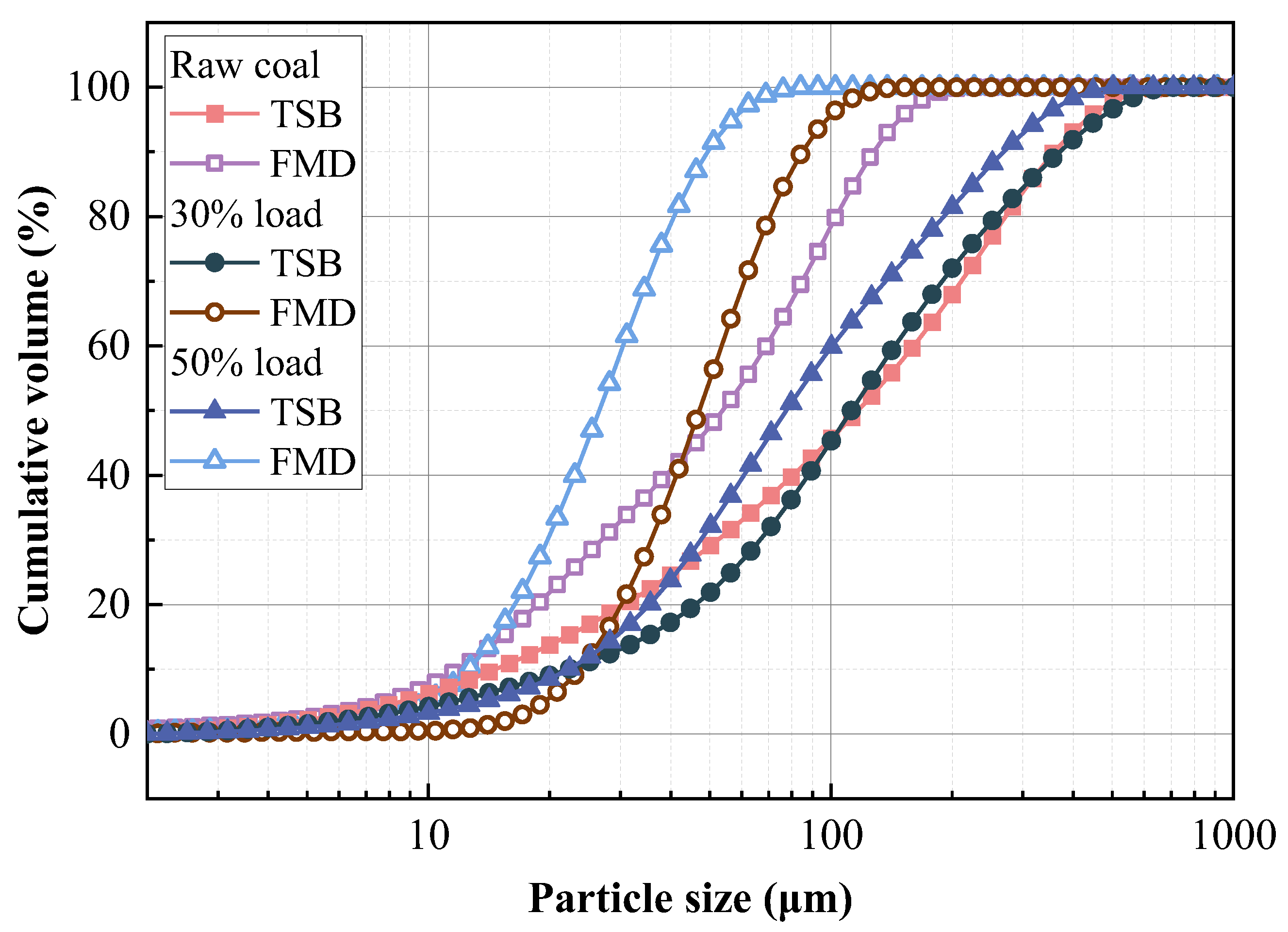
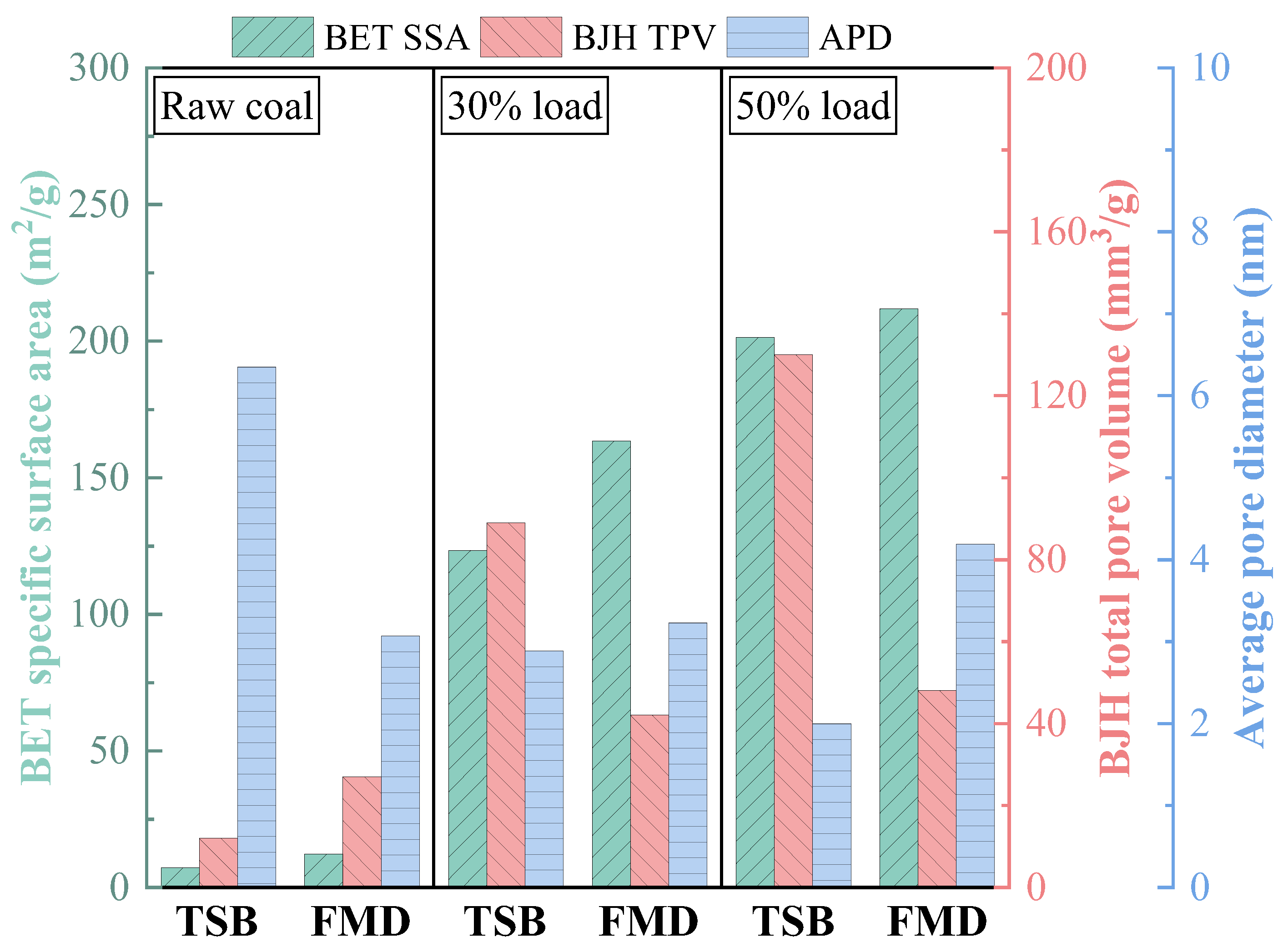
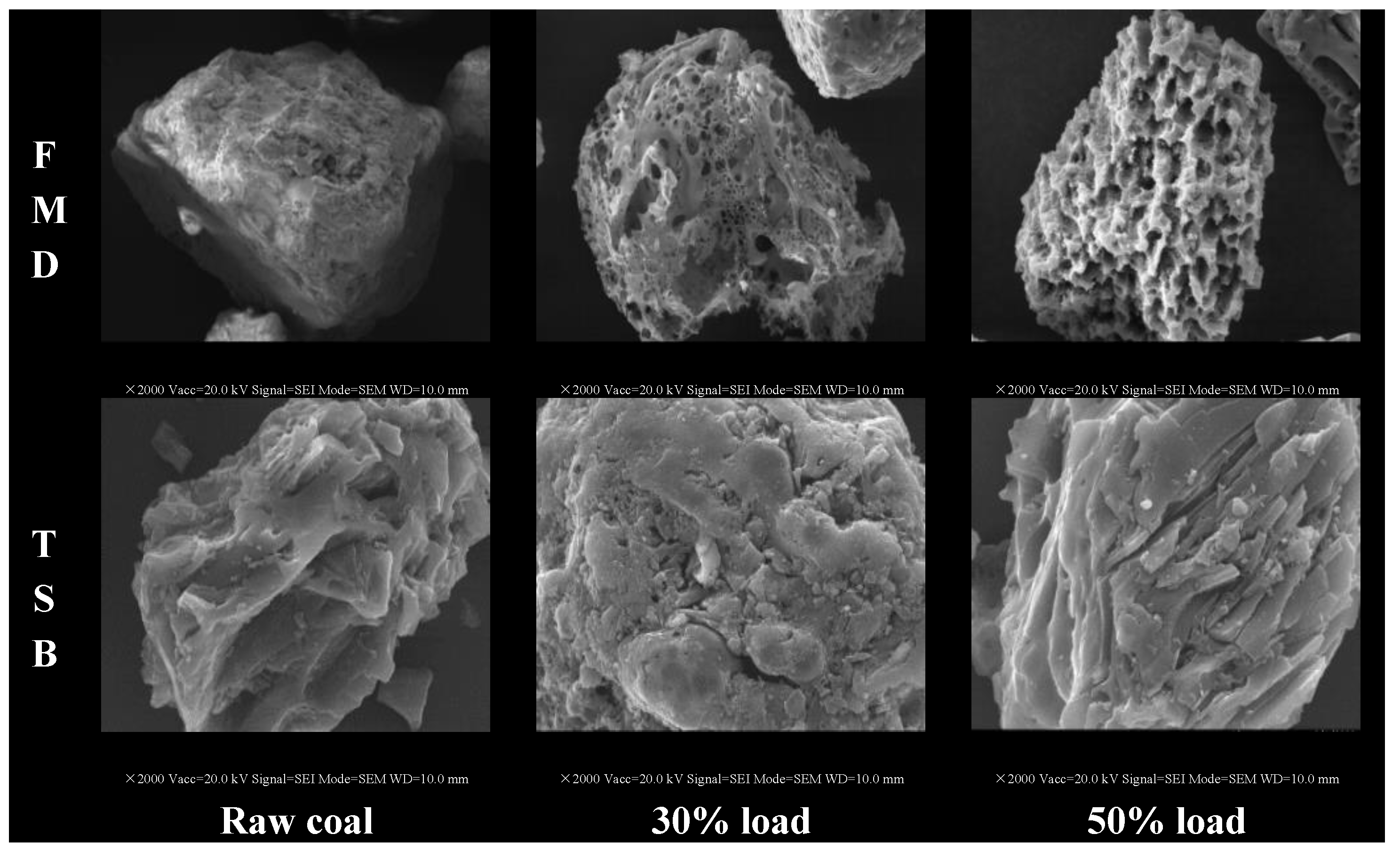
3.3.3. Physicochemical Properties of Preheated Char

Figure 27 shows the particle size distribution of raw coal and preheated char in TSB and FMD. In TSB, the particle size of preheated char under 50% load is obviously smaller than that under 30% load, indicating that the particle crushing effect is more obvious under high load, which is due to the large circulation amount of fuel particles under high load, resulting in intensified collisions between particles and strong thermal stress. For FMD, the particle size of preheated char under the same load is significantly smaller than that of TSB. This is because the preheating temperature in FMD is higher (Figure 24), which makes it easier to release volatiles during fuel modification (Figure 26). At the same time, due to the smaller volume of FMD, key velocity parameters are larger than those of TSB, which promotes the interaction between the particles and the gas, so the particle size of preheated char is smaller in FMD.
Figure 28 illustrates the SSA, TPV and APD of preheated char and raw coal. Under 30% load, SSA and TPV of the preheated char were markedly lower than those observed at 50% load, suggesting that the pore structure of the preheated char at this higher load was more developed, which could be attributed to both the temperature and UFV which has increased, particle collisions became increasingly vigorous, enhancing the intensity of thermochemical reactions and promoting micro-pore formation while concurrently reducing APD. At equivalent load, for FMD, SSA and APD of preheated char were larger than those for TSB. Nonetheless, its TPV remained smaller. This difference primarily stemmed from the synergistic effects of structural design and temperature variations. For FMD, the enhancement of preheated char’s SSA may spawn from the generation of a substantial number of micro-pores and a concomitant reduction in particle size, which eventually gave rise to a diminished TPV. Furthermore, elevated flow parameters promoted vigorous gas movement around the particles, allowing for an increased passage of gas through smaller pores rather than larger ones. In contrast, TSB’s lower temperature diminished combustion and gasification reaction intensities, resulting in an increase in medium-sized and large pores. To sum up, FMD exhibited a superior modification efficacy compared to TSB.
Figure 29 depicts the apparent morphology analysis of preheated char and raw coal. For TSB, the preheated char predominantly adopted a bubble-like structure characterized by discernible elongated cracks and slit pores. Conversely, for FMD, the preheated char primarily manifested a honeycomb architecture, where numerous holes were prominently visible on the particle surface, exhibiting significantly higher porosity and an enhanced degree of modification of BC. Moreover, at the same magnification, the particle size was significantly smaller than that of TSB. The changes in surface morphology of these particles were closely intertwined with the release of volatiles. This well-developed pore structure was likely to positively influence the combustion stability of the preheated char within the UFC.

3.3.4. NOx Emission and Combustion Efficiency

Figure 30 presents NOx emission, CO emission, η and combustible percentage of fly ash (Cf) for FMD and TSB.
For FMD, the preheated char displayed a larger SSA and higher APD (Figure 28), which facilitated faster O2 permeation into its interior, thus promoting more complete combustion and ameliorating overall efficiency. Additionally, a higher N conversion ratio reduced the potential for NOx formation in UFC (Figure 26) during BC modification. In contrast, TSB’s preheated char had a less favorable pore structure, ultimately resulting in lower η and possible localized high-temperature areas in the course of combustion. Aside from that, the decreased N conversion ratio during BC modification increased the likelihood of fuel-N being released as NOx in UFC. Both lower reductive gaseous species concentration and poorly modified solid phases diminished homogeneous and heterogeneous reduction capabilities for NOx (Figure 25 and Figure 28). For this reason, FMD proved more effective at reinforcing η while reducing NOx emissions. For FMD, stable combustion at a 30% low load, with an original NOx emission of 77.93 mg/m3 and a η of 98.59% was realized, surpassing TSB.

4. Conclusions

In an effort to cope well with the challenges of high production and operation cost, installation difficulty and environmental pollution, this study innovatively put forth an FMD, and comprehensively probed into the influences of buffer tank and operation load on operation stability, fuel modification, combustion characteristics and NOx emissions on an MW grade pilot-scale test platform. In addition, performance disparities were comparatively analyzed between FMD and TSB. The principal conclusions are as follows:
  • Adding the buffer tank enhanced operation stability of FMD, improved its modification conditions, and reduced NOx emissions. Under such circumstance, the carbon microcrystalline structure of preheated coal char was improved, and its specific surface area, pore volume, pore diameter, and fuel conversion rate increased. Notably, this condition promoted large migration of stable nitrogen functional groups into nitrogen-containing gases (mainly N2). The optimization of physiochemical properties of preheated coal char and the massive solid-phase nitrogen reduction facilitated NOx emission reduction.
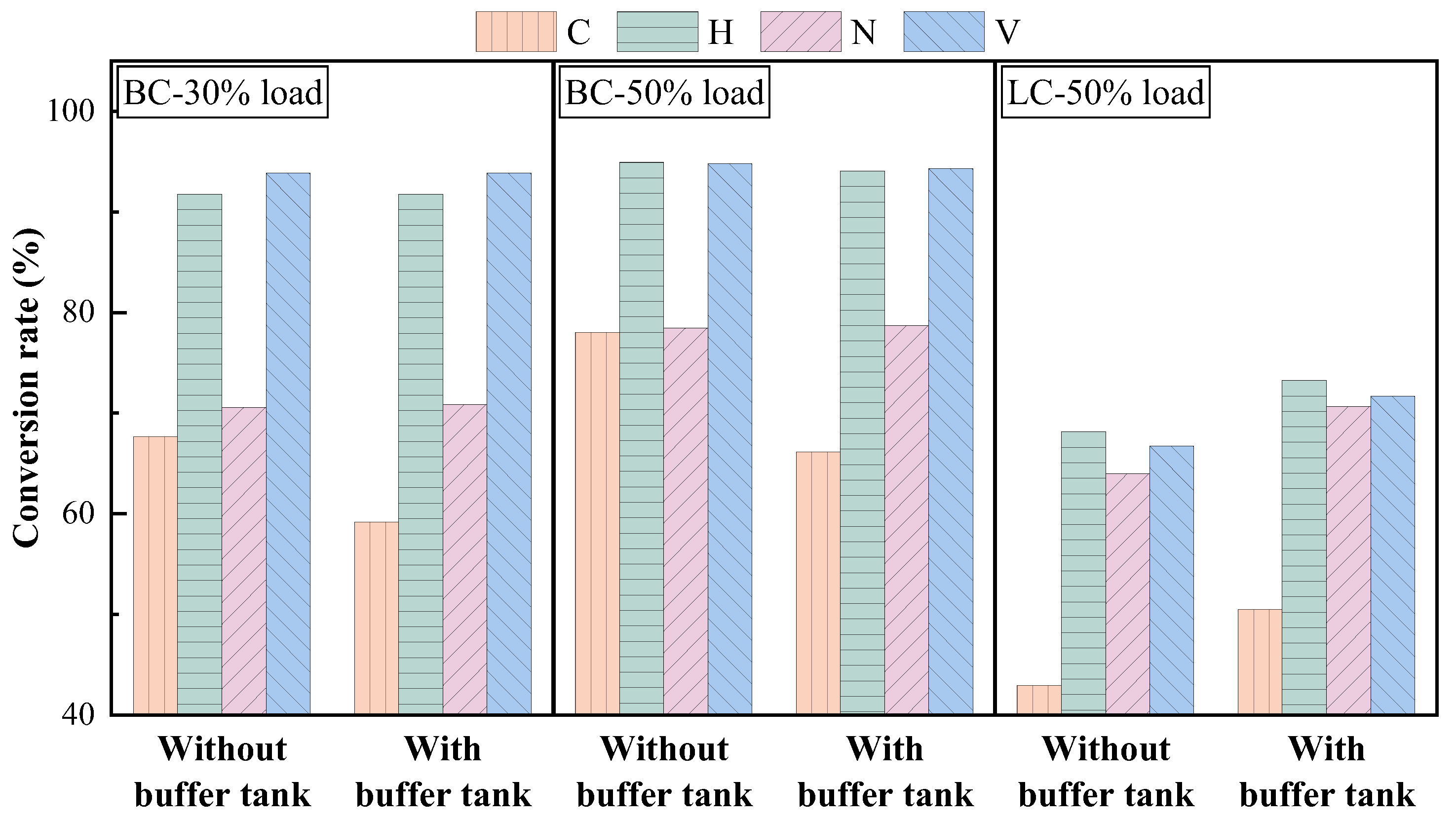
  • The influence of load on fuel modification, combustion and NOx emissions was regulated by volatile content. The optimal modification efficiency was achieved at 50% and 100% loads for high-volatile and low-volatile coals, respectively. Moreover, η increased for high-volatile coal as load increased, but with NOx emissions increasing. By contrast, this condition reduced NOx emissions with high η for low-volatile coal.
  • In comparison with TSB, FMD (equipped with a buffer tank) illustrated more conspicuous advantages in stable operation, fuel modification and NOx emission control. FMD suggested more remarkable advantages with regard to the enhancement of burnable gas yields in preheated coal gas and the betterment of physicochemical properties of preheated coal char. Moreover, clean and efficient combustion was more easily realized with the FMD design.
  • The coal self-preheating combustion technology demonstrated exceptional advantages in stable combustion and NOx emission control at low loads of coal-fired boilers. In industrial applications, the appropriate FMD or TSB should be chosen rooted in diverse application requirements. By optimizing burner structure and operational parameters, original NOx emissions could decrease to a minimum of 77.93 mg/m3 with high η of 98.59% at low load of 30%.

Author Contributions

Conceptualization, H.D.; Methodology, H.D. and S.Z.; Formal analysis, S.L.; Investigation, S.L., S.Z., X.Z., H.Z., K.S., H.W. and J.H.; Writing-original draft, H.D.; Writing-review & editing, Z.O.; Supervision, Z.O.; Project administration, H.D. and Z.O. All authors have read and agreed to the published version of the manuscript.

Funding

This research was funded by Postdoctoral Fellowship Program of CPSF [GZC20232672] and Strategic Priority Research Program of the CAS [XDA29010200].

Data Availability Statement

The original contributions presented in the study are included in the article, further inquiries can be directed to the corresponding author.

Conflicts of Interest

The authors declare no conflict of interest.

Nomenclature

Symbols
CfCombustible Percentage of Fly Ash, %
MPPrimary Air Flow Rate, Nm3/h
MSSecondary Air Flow Rate, Nm3/h
MTTertiary Air Flow Rate, Nm3/h
MTotal Air Flow Rate, Nm3/h
N-5Pyrrole and Pyrrolidine Nitrogen
N-6Pyridine Nitrogen
N-XPyridine Nitrogen-oxide
N-QProtonated Pyridine Nitrogen
Qnet,arLow Heating Value, MJ/kg
UFVFluidized Air Velocity, m/s
UCICyclone Separator Inlet Velocity, m/s
UCOCyclone Separator Outlet Velocity, m/s
Greek letters
λTotal Air Ratio, %
λpPrimary Air Ratio, %
λSSecondary Air Ratio, %
λTTertiary Air Ratio, %
ηCombustion Efficiency, %
Abbreviations
APDAverage Pore Diameter, nm
BCShenmu Bituminous Coal
BETBrunauer Emmett Teller
BJHBarrett Joyner Halenda
CFBCirculating Fluidized Bed
CVCalorific Value, MJ/Nm3
FMDNovel Compact Fluidized Modification Device
LCShanxi Lean Coal
PLCProgrammable Logic Controller
SEMScanning Electron Microscopy
SCRSelective Catalytic Reduction
SSASpecific Surface Area, m2/g
TPVTotal Pore Volume, cm3/g
TSBTraditional Self-preheating Burners
UFCUp-fired Combustion Chamber

References

  1. Chen, Z.; Tan, Y.; Xu, J. Economic and environmental impacts of the coal-to-gas policy on households: Evidence from China. J. Clean. Prod. 2022, 341, 130608. [Google Scholar] [CrossRef]
  2. Li, J.; Li, X.; Yan, P.; Zhou, G.; Liu, J.; Yu, D. Thermodynamics, flexibility and technoeconomics assessment of a novel integration of coal-fired combined heating and power generation unit and compressed air energy storage. Appl. Energy 2023, 339, 120924. [Google Scholar] [CrossRef]
  3. Qian, Q.; Tian, Y.; Lin, L.; Feng, L.; Shao, Z.; Xie, K. Modelling the socio-economic impacts of coal production reduction: A macro provincial analysis of China. Energy Rep. 2024, 12, 4306–4319. [Google Scholar] [CrossRef]
  4. Wang, Q.; Guo, J.; Li, R.; Jiang, X. Exploring the role of nuclear energy in the energy transition: A comparative perspective of the effects of coal, oil, natural gas, renewable energy, and nuclear power on economic growth and carbon emissions. Environ. Res. 2023, 221, 115290. [Google Scholar] [CrossRef]
  5. Wu, Y.; Wang, Z.; Shi, C.; Jin, X.; Xu, Z. A novel data-driven approach for coal-fired boiler under deep peak shaving to predict and optimize NOx emission and heat exchange performance. Energy 2024, 304, 132106. [Google Scholar] [CrossRef]
  6. Wang, H.; Zou, C.; Hu, H.; Gu, G.; Dong, L.; Huang, Y.; Deng, S.; Li, S. Migration and emission characteristics of trace elements in coal-fired power plant under deep peak load regulation. Sci. Total Environ. 2023, 868, 161626. [Google Scholar] [CrossRef]
  7. Jin, W.; Si, F.; Kheirkhah, S.; Yu, C.; Li, H.; Wang, Y. Numerical study on the effects of primary air ratio on ultra-low-load combustion characteristics of a 1050 MW coal-fired boiler considering high-temperature corrosion. Appl. Therm. Eng. 2023, 221, 119811. [Google Scholar] [CrossRef]
  8. Ma, D.; Zhang, S.; He, X.; Zhang, J.; Ding, X. Combustion stability and NOx emission characteristics of a 300 MWe tangentially fired boiler under ultra-low loads with deep-air staging. Energy 2023, 269, 126795. [Google Scholar] [CrossRef]
  9. Zeng, G.; Zhou, A.; Fu, J.; Ji, Y. Experimental and numerical investigations on NOx formation and reduction mechanisms of pulverized-coal stereo-staged combustion. Energy 2022, 261, 125358. [Google Scholar] [CrossRef]
  10. Chen, Z.; Qiao, Y.; Guan, S.; Wang, Z.; Zheng, Y.; Zeng, L.; Li, Z. Effect of inner and outer secondary air ratios on ignition, C and N conversion process of pulverized coal in swirl burner under sub-stoichiometric ratio. Energy 2022, 239, 122423. [Google Scholar] [CrossRef]
  11. Zhang, Q.; Zhang, S.; Chen, W. Provincial pathways to carbon-neutral energy systems in China considering interprovincial electricity transmission development. Appl. Energy 2024, 375, 123953. [Google Scholar] [CrossRef]
  12. Zhang, H.; Lin, H.; Zhou, X.; Wang, X.; Zheng, H.; Liu, Y.; Tan, H. CFD modeling and industry application of a self-preheating pulverized coal burner of high coal concentration and enhanced combustion stability under ultra-low load. Appl. Therm. Eng. 2024, 253, 123831. [Google Scholar] [CrossRef]
  13. Shen, T.; Song, M.; Huang, Y.; Zhu, R.; Li, Z.; Yu, Q.; Lu, P.; Wang, M. The effectiveness of a novel coal-igniting-fuel technology and application in a direct current burner. Fuel 2021, 306, 121503. [Google Scholar] [CrossRef]
  14. Li, S.; Chen, Z.; He, E.; Jiang, B.; Li, Z.; Wang, Q. Combustion characteristics and NOx formation of a retrofitted low-volatile coal-fired 330 MW utility boiler under various loads with deep-air-staging. Appl. Therm. Eng. 2017, 110, 223–233. [Google Scholar] [CrossRef]
  15. Zhu, G.; Gong, Y.; Niu, Y.; Wang, S.; Lei Yu Hui, S. Study on NOx emissions during the coupling process of preheating combustion of pulverized coal with multi-air staging. J. Clean. Prod. 2021, 292, 126012. [Google Scholar] [CrossRef]
  16. Su, X.; Fang, Q.; Ma, L.; Yao, B.; Li, Y.; Zhao, X.; Mao, R.; Yin, C. Improving combustion and lowering NOx emissions of an industrial coal swirl burner by optimizing its nozzle structure. Appl. Therm. Eng. 2023, 218, 119340. [Google Scholar] [CrossRef]
  17. Tang, H.; Xu, Z.; Han, X.; Sun, L.; Liu, Y.; Shen, X.; Liu, Z. Design method and experimental study on a novel self-sustaining internal combustion burner. Energy 2024, 308, 133039. [Google Scholar] [CrossRef]
  18. Zhang, X.; Zhu, S.; Zhu, J.; Liu, Y.; Zhang, J.; Hui, J.; Ding, H.; Cao, X.; Lyu, Q. Preheating and combustion characteristics of anthracite under O2/N2, O2/CO2 and O2/CO2/H2O atmospheres. Energy 2023, 274, 127419. [Google Scholar] [CrossRef]
  19. Su, K.; Ouyang, Z.; Wang, H.; Zhang, J.; Ding, H.; Wang, W. Research on purification, combustion and NO emission characteristics of pulverized coal preheated by a novel self-sustained purifying burner. Fuel 2024, 366, 131436. [Google Scholar] [CrossRef]
  20. Liu, Y.; Liu, J.; Lyu, Q.; Zhu, J.; Pan, F. Microstructure analysis of fluidized preheating pulverized coal under O2/CO2 atmospheres. Fuel 2021, 292, 120386. [Google Scholar] [CrossRef]
  21. Zhu, S.; Hui, J.; Lyu, Q.; Ouyang, Z.; Zeng, X.; Zhu, J.; Liu, J.; Cao, X.; Zhang, X.; Ding, H.; et al. Experimental study on pulverized coal swirl-opposed combustion preheated by a circulating fluidized bed. Part A. Wide-load operation and low-NOx emission characteristics. Energy 2023, 284, 128573. [Google Scholar] [CrossRef]
  22. Hui, J.; Zhu, S.; Zhang, X.; Liu, Y.; Lin, J.; Ding, H.; Su, K.; Cao, X.; Lyu, Q. Experimental study of deep and flexible load adjustment on pulverized coal combustion preheated by a circulating fluidized bed. J. Clean. Prod. 2023, 418, 138040. [Google Scholar] [CrossRef]
  23. Wang, H.; Ouyang, Z.; Ding, H.; Su, K.; Zhang, J.; Hu, Y. Experimental study on the flexible peak shaving with pulverized coal self-preheating technology under load variability. Energy 2024, 289, 129830. [Google Scholar] [CrossRef]
  24. Wu, H.; Cai, J.; Ren, Q.; Xu, J.; Chu, F.; Lyu, Q. An efficient and economic denitration technology based on fuel pretreatment for cement cleaner production. J. Clean. Prod. 2020, 272, 122669. [Google Scholar] [CrossRef]
  25. Brunauer, S.; Emmett, P.; Teller, E. Adsorption of Gases in Multimolecular Layers. J. Am. Chem. Soc. 1938, 60, 309–319. [Google Scholar] [CrossRef]
  26. Webb, P.; Orr, C.; Camp, R.; Olivier, J.; Yunes, Y. Analytical Methods in Fine Particle Technology; Micromeritics Instrument Corp: Norcross, GA, USA, 1997. [Google Scholar]
  27. Shao, Z.; Wang, S.; Zhao, Y.; Ren, T.; Chu, Z.; Xiang, P.; Liu, X. Staged Combustion Characteristics of Natural Gas Low-Emission Tower Coaxial Fuel. J. Combust. Sci. Technol. 2023, 29, 606616. [Google Scholar]
  28. Tong, B.; Li, J.; Cheng, T.; Zhao, Z.; Cheng, L.; Lyu, J. Investigation on the Criterion of the Air Distribution Uniformity in a Circulating Fluidized Bed Boiler and the Improved Test Method. J. Chin. Soc. Power Eng. 2023, 43, 823–828. [Google Scholar] [CrossRef]
  29. Sekret, R. An analysis of temperature distribution and heat transfer in a large-scale CFB boilers. Rynek Energii 2011, 6, 145–151. [Google Scholar]
  30. Ding, H.; Ouyang, Z.; Zhang, X.; Zhu, S. The effects of particle size on flameless combustion characteristics and NOx emissions of semi-coke with coal preheating technology. Fuel 2021, 297, 120758. [Google Scholar] [CrossRef]
  31. Meng, H.; Yang, H.; Wu, Z.; Li, D.; Wang, Z.; Wang, D.; Wang, H.; Li, H.; Li, J. Co-pyrolysis of mushroom residue blended with pine sawdust/wheat straw for sustainable utilization of biomass wastes: Thermal characteristics, kinetic/thermodynamic analysis, and structure evolution of co-pyrolytic char. Sustainability 2024, 16, 6677. [Google Scholar] [CrossRef]
  32. Ryoichi, K.; Hiromitsu, M.; Hisao, M.; Akira, S. Characteristics of particulate matter generated in pressurized coal combustion for high-efficiency power generation system. Adv. Powder Technol. 2003, 14, 673–694. [Google Scholar] [CrossRef]
  33. Xi, J.; Liang, J.; Sheng, X.; Shi, L.; Li, S. Characteristics of lump lignite pyrolysis and the influence of temperature on lignite swelling in underground coal gasification. J. Anal. Appl. Pyrolysis 2016, 117, 228–235. [Google Scholar] [CrossRef]
  34. Rong, L.; Xiao, J.; Wang, X.; Sun, J.; Jia, F.; Chu, M. Low-rank coal drying behaviors under negative pressure: Thermal fragmentation, volume shrinkage and changes in pore structure. J. Clean. Prod. 2020, 272, 122572. [Google Scholar] [CrossRef]
  35. Pels, J.; Kapteijn, F.; Moulijn, J.; Zhu, Q.; Thomas, K. Evolution of nitrogen functionalities in carbonaceous materials during pyrolysis. Carbon 1995, 33, 1641–1653. [Google Scholar] [CrossRef]
  36. Phiri, Z.; Everson, R.; Neomagus, H.; Wood, B. Transformation of nitrogen functional forms and the accompanying chemical-structural properties emanating from pyrolysis of bituminous coals. Appl. Energy 2018, 216, 414–427. [Google Scholar] [CrossRef]
  37. Liu, X.; Zheng, Y.; Liu, Z.; Ding, H.; Huang, X.; Zheng, C. Study on the evolution of the char structure during hydrogasification process using Raman spectroscopy. Fuel 2015, 157, 97–106. [Google Scholar] [CrossRef]
  38. Guo, S.; Yang, W.; Yuan, S.; Yan, Z.; Geng, W. Experimental investigation of erosion effect on microstructure and oxidation characteristics of long-flame coal. Energy 2022, 259, 124959. [Google Scholar] [CrossRef]
  39. Hernández, J.J.; Aranda-Almansa, G.; Bula, A. Gasification of biomass wastes in an entrained flow gasifier: Effect of the particle size and the residence time. Fuel Process. Technol. 2010, 91, 681–692. [Google Scholar] [CrossRef]
  40. Schmiers, H.; Friebel, J.; Streubel, P.; Hesse, R.; Kopsel, R. Change of chemical bonding of nitrogen of polymeric N-heterocyclic compounds during pyrolysis. Carbon 1999, 37, 1965–1978. [Google Scholar] [CrossRef]
  41. Zhu, S.; Hui, J.; Lyu, Q.; Ouyang, Z.; Liu, J.; Zhu, J.; Zeng, X.; Zhang, X.; Ding, H.; Liu, Y.; et al. Experimental study on pulverized coal combustion preheated by a circulating fluidized bed: Preheating characteristics for peak shaving. Fuel 2022, 324, 124684. [Google Scholar] [CrossRef]
Figure 1. Miniaturization strategy of the traditional self-preheating burner.
Energies 18 02555 g001
Figure 2. Schematic diagram of the MW grade pilot-scale test platform for peak shaving.
Energies 18 02555 g002
Figure 3. Particle size distribution of BC and LC.
Energies 18 02555 g003
Figure 4. Temperature distributions of FMD during stable operation time with/without the buffer tank.
Energies 18 02555 g004
Figure 5. Pressure distribution at the bottom of the FMD during stable operation time with/without the buffer tank.
Energies 18 02555 g005
Figure 6. Principal components and CVs of the combustible gas with/without the buffer tank.
Energies 18 02555 g006
Figure 7. Conversion ratio of each component during fuel modification with/without the buffer tank.
Energies 18 02555 g007
Figure 8. Particle size distribution of preheated char and raw coal with/without the buffer tank.
Energies 18 02555 g008
Figure 9. SSA, TPV and APD of preheated char and raw coal with/without the buffer tank.
Energies 18 02555 g009
Figure 10. Apparent morphology analysis of preheated char and raw coal with/without the buffer tank.
Energies 18 02555 g010
Figure 11. Fitting results of XPS-N1s spectrum of preheated char and raw coal with/without the buffer tank.
Energies 18 02555 g011aEnergies 18 02555 g011b
Figure 12. Relative content of N functional groups in preheated char and raw coal with/without the buffer tank.
Energies 18 02555 g012
Figure 13. Raman spectrum intensity and peak fitting of preheated char and raw coal with/without the buffer tank.
Energies 18 02555 g013aEnergies 18 02555 g013b
Figure 14. Raman analysis of preheated char and raw coal with/without the buffer tank.
Energies 18 02555 g014
Figure 15. NOx and CO emission with/without the buffer tank.
Energies 18 02555 g015
Figure 16. Principal components and CVs of the combustible gas at different loads.
Energies 18 02555 g016
Figure 17. Conversion ratio of each component during fuel modification at different loads.
Energies 18 02555 g017
Figure 18. Particle size distribution of preheated char at different loads.
Energies 18 02555 g018
Figure 19. SSA, TPV and APD of preheated char at different loads.
Energies 18 02555 g019
Figure 20. Apparent morphology analysis of preheated char at different loads.
Energies 18 02555 g020
Figure 21. Relative content of N functional groups in preheated char at different loads.
Energies 18 02555 g021
Figure 22. Raman analysis of preheated char at different loads.
Energies 18 02555 g022
Figure 23. NOx and CO emission at different loads.
Energies 18 02555 g023
Figure 24. Temperature and pressure distributions for FMD and TSB.
Energies 18 02555 g024
Figure 25. Principal components and CVs of combustible gas for FMD and TSB.
Energies 18 02555 g025
Figure 26. Conversion ratio of each component during fuel modification for FMD and TSB.
Energies 18 02555 g026
Figure 27. Particle size distribution of preheated char and raw coal for FMD and TSB.
Energies 18 02555 g027
Figure 28. SSA, TPV and APD of preheated char and raw coal for FMD and TSB.
Energies 18 02555 g028
Figure 29. Apparent morphology analysis of preheated char and raw coal for FMD and TSB.
Energies 18 02555 g029
Figure 30. NOx emission, CO concentration, η and Cf for FMD and TSB.
Energies 18 02555 g030
Table 1. Ultimate and proximate analysis of the two pulverized coal.
ItemsBCLC
Ultimate analysis (wt. %, as-received)
Carbon (Car)73.6054.69
Hydrogen (Har)4.302.82
Oxygen (Oar)11.434.86
Nitrogen (Nar)0.940.85
Sulfur (Sar)0.321.66
Proximate analysis (wt. %, as-received)
Moisture (Mar)4.930.72
Volatile matter (Var)32.5913.36
Fixed carbon (FCar)58.0051.52
Ash (Aar)4.4834.40
Low heating value (Qnet, ar, MJ/kg)28.4921.03
Table 2. Experimental conditions.
ItemsUnitCase 1Case 2Case 3Case 4Case 5Case 6Case 7Case 8
Fuel-BCLC
Load%303050501005050100
Fuel feed ratekg/h393864651298785172
Thermal powerMW0.300.300.500.501.000.500.501.00
Buffer tank-WithoutWithWithoutWithWithWithoutWithWith
MPNm3/h505182871708583178
λP-0.180.180.180.180.180.180.180.19
UFVm/s1.531.562.502.665.202.572.515.39
UCIm/s7.427.5712.1712.9225.2412.5012.2126.18
UCOm/s10.0510.2516.4817.4934.1816.9316.5335.45
MSNm3/h145136234238490244243492
λS-0.510.490.500.500.520.510.520.52
MBNm3/h142150243238490254239496
λB-0.500.540.520.500.520.530.510.52
MNm3/h33733755956311505835651166
λ-1.191.211.201.181.221.221.211.23
Disclaimer/Publisher’s Note: The statements, opinions and data contained in all publications are solely those of the individual author(s) and contributor(s) and not of MDPI and/or the editor(s). MDPI and/or the editor(s) disclaim responsibility for any injury to people or property resulting from any ideas, methods, instructions or products referred to in the content.

