Article

Low Voltage Ride Through Coordination Control Strategy of DFIG with Series Grid Side Converter

1
China Electric Power Research Institute Wuhan Branch, Wuhan 430074, China
2
College of Electrical Engineering and New Energy, China Three Gorges University, Yichang 443000, China
*
Author to whom correspondence should be addressed.
Energies 2025, 18(10), 2537; https://doi.org/10.3390/en18102537
Submission received: 5 April 2025 / Revised: 7 May 2025 / Accepted: 11 May 2025 / Published: 14 May 2025
(This article belongs to the Special Issue Control and Optimization of Power Converters)

Abstract

:
The present study investigates the control strategy of a novel doubled-fed induction generator (DFIG) with a series grid-side converter (SGSC) during grid faults. The rotor-side inverter is subject to a control strategy derived from the Model Predictive Current Control (MPCC) theory, which is implemented during periods of fault occurrence; for the series grid-side converter, the positive and negative sequence component control is implemented during both steady state and fault periods to enhance system stability and performance. The proposed coordinated control strategy is implemented on a doubly fed turbine with SGSC, while taking into account different degrees of symmetric and asymmetric faults to further evaluate the efficacy of the proposed method. The results of the simulations demonstrate the efficacy of the model-predictive current control scheme applied to the rotor-side converter under conditions of asymmetric faults. This enables the suppression of a range of phenomena, including rotor overcurrent, stator overcurrent, and overvoltage, electromagnetic torque ripple, and DC bus voltage during low-voltage ride-through (LVRT), among others. The present study confirms the viability of implementing positive and negative sequences of voltage separation control in the SGSC during both grid faults and steady state. This approach is expected to minimize the switching of SGSC control strategies and thereby reduce output power fluctuations. The Rotor Side Converter (RSC) and SGSC can perform coordinated control during faults, and the proposed method is able to improve low-voltage ride-through performance compared to existing methods, thereby preventing damage to the converter under multiple fault conditions.

1. Introduction

The recent augmentation in wind power grid-connected capacity has been accompanied by the formulation of novel grid operation guidelines that explicitly delineate the requirements for the operation of grid-connected reactive power in large-capacity wind power systems. A further consideration is imperative to guarantee that grid-connected power quality requirements are satisfied. It is therefore essential that the negative sequence content of the grid-connected current remains within a specified range. To fulfill the voltage ride-through technical requirements of the power generation system under the recently enacted power grid regulations, scholars have proposed a new topology to enhance the performance of the DFIG system when connected to the grid. Most scholars firstly optimize the control strategy of SGSC under grid imbalance [1,2,3,4,5,6]. The LVRT operation of DFIG is considered to be the biggest challenge of wind power grid-connected technology [7]. To meet the technical requirements for low-voltage ride-through capability of power generation systems under the new grid regulations, some scholars have also investigated the DFIG performance with improved topologies. For instance, as posited by literature [8], a shift from a parallel to a series configuration is proposed for the connection of the grid-side converter to the grid. This novel configuration offers distinct advantages in terms of fault ride-through capability. However, related studies have identified challenges associated with the doubly fed converter system employing this scheme, including inadequate power handling capacity [9]. Consequently, the extant literature [10,11] displays the integration of a parallel grid-side converter with the series grid-side converter. This configuration is employed to enhance the system’s power handling capacity, thereby facilitating ride-through under balanced three-phase short-circuit conditions. However, the existing literature has primarily focused on the investigation of the controls for the purpose of total output power control in doubly fed converter systems that utilize SGSC. A paucity of in-depth research exists with respect to the control of the system for the purpose of suppressing the output current in the event of grid faults.
Model Predictive Control (MPC) [12] is a technique that employs a system model to forecast future states and output variables. By continuously optimizing control inputs based on an objective function, it determines the most effective control strategy. As detailed in Reference [13], the utilization of MPC strategies within the domain of power electronic systems has been thoroughly investigated and presented. This paper provides a comprehensive explanation of how Finite Control Set Model Predictive Control (FCS-MPCC) can be applied to power converters. In addition, various studies have introduced anticipatory current regulation strategies designed specifically for doubly fed induction machines operating within wind energy generation frameworks. This model is based on the maximum wind energy tracking model of double-fed wind turbines. Reference [14] applied MPC theory to a solid-state transformer and effectively suppressed power quality harmonics. Reference [15] designed MPCC based on doubly fed wind turbine to solve the problem of DC bus voltage overrun.
To maintain generator voltage and ensure DFIG connectivity during voltage dips, coordinated control of the RSC and SGSC is employed for effective voltage dip mitigation. The new control strategy proposed here comes from the perspective of limiting the transient DC component and the negative sequence power frequency component. To manage the operation of the RSC and the SGSC in the DFIG configuration, a control strategy is formulated that incorporates model predictive current regulation in conjunction with a T/4 delay-based separation technique for decomposing the voltage into its symmetrical positive and negative sequence components. In the following, it is verified that the use of MPCC during the fault can effectively suppress the overcurrent and reduce the DC bus voltage amplitude, so that the effectiveness of the GSC can be guaranteed to achieve power support. Furthermore, it is demonstrated that separating the positive and negative sequences enables smooth SGSC control in steady-state conditions. The study indicates that this work enhances the LVRT capability of the DFIG system, improving the adaptability of grid-integrated doubly fed wind turbines to grid disturbances.
The innovations of this paper are as follows:
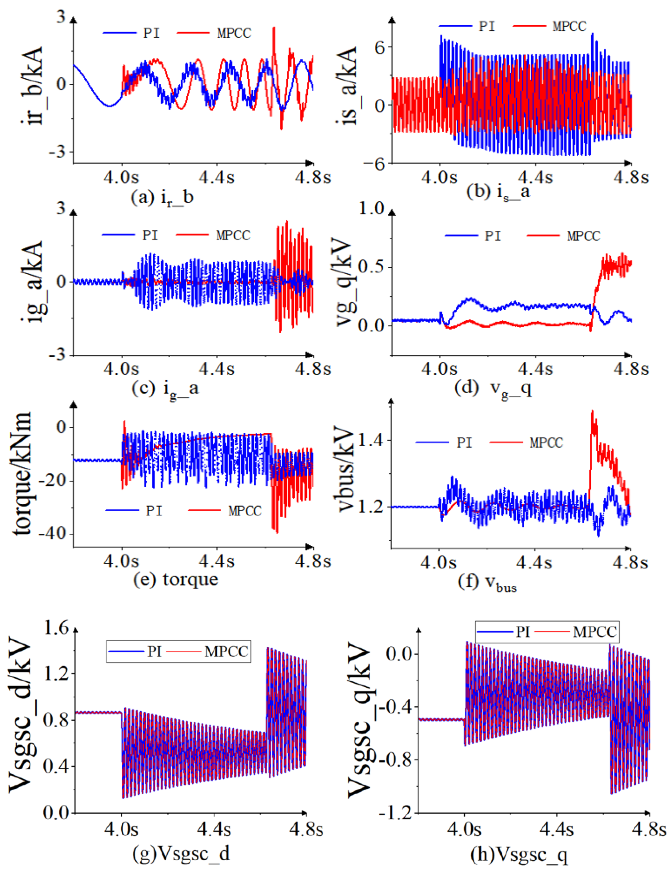
  • A voltage ride-through strategy is developed through coordinated control of the SGSC and RSC, where regulation of the SGSC output voltage suppresses the stator flux transient component, and the MPCC strategy enables the RSC to directly track the rotor current, effectively mitigating overcurrent issues. For example, in a single-phase ground fault, the stator current fluctuation range under traditional PI control is −7.14 to 7.14 kA, whereas the improved coordinated control reduces it to −4.3 to 4.3 kA, a reduction of about 40%;
  • This paper also introduces the T/4 delayed voltage separation control strategy applied to SGSC for positive and negative sequence component separation under both steady-state and fault conditions. Equation (12) shows how to achieve voltage positive and negative sequence separation, thereby avoiding the time delay problem of the traditional PI controller. Simulation results indicate that this strategy can limit the DC-link voltage fluctuation range between 1.17 and 1.22 kV during a single-phase short circuit fault, significantly improving system stability compared to traditional PI control.

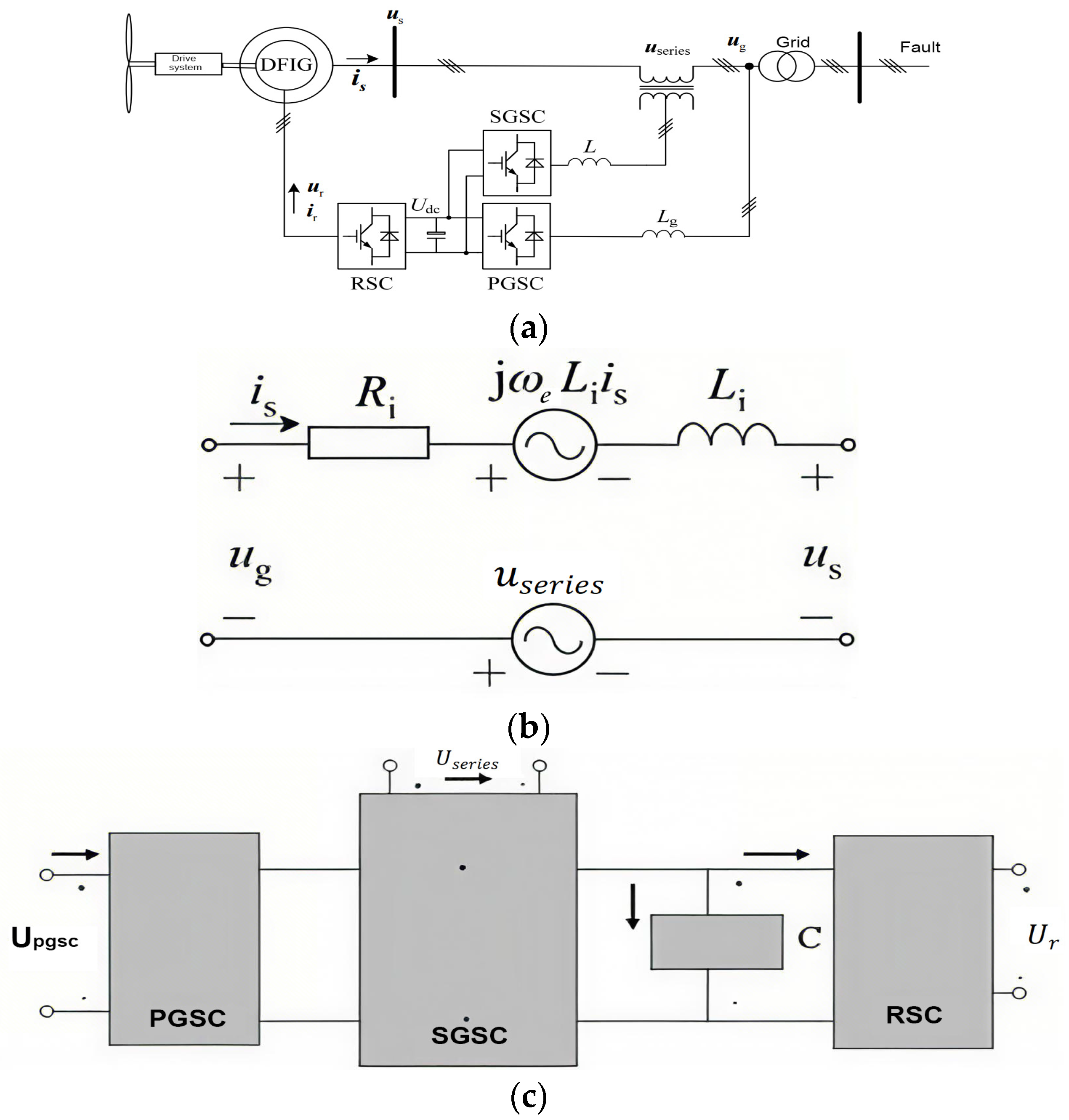
2. The DFIG Model with SGSC

Compared with the mainstream DFIG system, the topology of the DFIG system using SGSC has changed. It is an SGSC and a series transformer added to the generator stator side in the original topology. The topology is shown in the Figure 1a.
As shown in Figure 1a, the DFIG stator voltage vector results from the superposition of the grid voltage and the compensation voltage injected through the series transformer.
The stator voltage space vector of the DFIG can be manipulated by regulating the voltage generated by the SGSC, thereby optimizing the transition process of the DFIG when the power grid is faulty. But whether a good low-voltage transition operation can be achieved depends on the optimization result of the control strategy. In order to facilitate the analysis of the problem and simplify the design of the control scheme, a simplified equivalent circuit is used in the series transformer, that is, the excitation branch of the series transformer is ignored. As depicted in Figure 1b, the SGSC voltage within the synchronous rotating coordinate system can be mathematically described as follows:
u g = R i i s + j ω e L i i s + L i d i s d t + u s u s e r i e s
P s e r i e s + j Q s e r i e s = u s e r i e s i ^ s
where: u s is the generator stator voltage space vector in the static coordinate axis system; u s e r i e s is the series voltage space vector injected by the series transformer; u g is the grid voltage space vector; R i is the series transformer resistance and input filter resistance; L i is the series transformer leakage inductance and filter inductance; P s e r i e s , Q s e r i e s represent the real and reactive power transmitted through the series-connected grid converter, respectively.
The mathematical representations of both the stator and rotor sides of the DFIG are formulated as follows:
u s = R s i s + d φ s d t u r = R r i r + d φ r d t
In the rotor coordinate system, the flux linkage of stator and rotor is expressed as:
φ s = L s i s + L m i r φ r = L r i r + L m i s
In Equations (4) and (5): u s , u r and i s , i r denote the stator and rotor voltages and currents in the stationary reference frame, respectively; φ s , φ r are their flux linkages; R s , R r and L s , L r represent the stator and rotor resistances and self-inductances; L m is the mutual inductance; ω r is the rotor speed. From the state-space Equation (5), the stator and rotor flux linkage dynamics can be derived:
φ r = L m L s φ s + σ L r i r
In this context, σ denotes the leakage inductance coefficient.
σ = ( 1 L m 2 / L s L r )
Substituting Equation (6) into Equation (4) enables the derivation of the connection between the rotor voltage and the stator flux.
u r = L m L s d φ s d t + ( σ L r + R r ) i r
As shown in Figure 1c, when the DC bus voltage of the DFIG system is constant, the following relationship exists:
P g P r P s e r i e s = 0
In the above equation: P g is the power of the parallel grid-side converter, and P r is the power of the rotor-side converter.

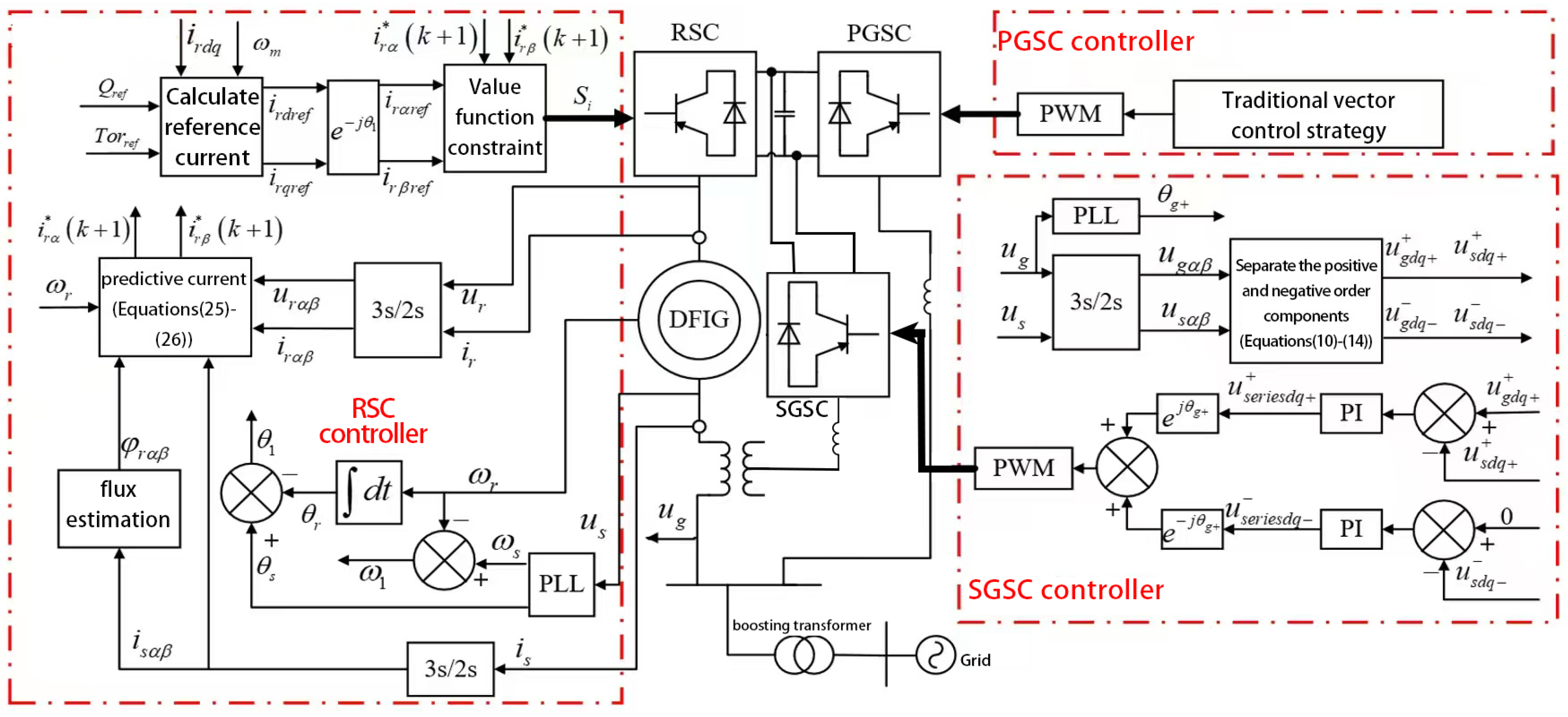
3. Coordinated Control of Voltage Ride Through Based on SGSC and RSC

In a typical DFIG setup, the generator stator is directly connected to the power grid. When a grid fault causes voltage sag, the stator flux will include a transient DC component, along with both positive and negative components (the latter occurring during unbalanced faults). The transient DC component is one of the main causes of rotor overcurrent. For the DFIG system using SGSC, the introduction of SGSC can make the stator voltage flexible and controllable. If the output voltage is adjusted to suppress the stator flux’s DC offset during faults, rotor over-current protection is achieved. However, the PI controller with sequence separation requires decomposing the current and voltage feedback into their respective components. It will cause a time delay in the feedback amount, thereby reducing the responsiveness and overall dynamic efficiency of the control system [16]. Therefore, it is necessary to introduce RSC control on the basis of SGSC control to suppress overvoltage and overcurrent.

3.1. Improved Control of SGSC During Grid Steady State and Fault

When the grid voltage is normal, RSC and PGSC employ vector control for generator power regulation and DC link voltage stabilization. The RSC uses traditional vector control. In the conventional vector control strategy, the three-phase stator current of the asynchronous machine is transformed into current components in the two-phase stationary reference frame (αβ axis). Subsequently, a coordinate transformation (Park transformation) is applied to equivalently convert these components into direct current components in the synchronous rotating reference frame (dq axis). The PGSC employs a traditional PI control strategy, while the SGSC adopts positive and negative sequence separation control during asymmetric faults and PI control during symmetric conditions. For SGSC, some scholars proposed that the control expression of positive and negative sequence separation can be used for the control of DFIG when the power grid is normal and unbalanced at the same time [17]. However, the author did not conduct valid verification. Therefore, it is inspired to apply the T/4 delay voltage separation control to the SGSC control under steady state and fault conditions in this paper. This is to reduce the switching of control strategies in case of failure, and its effectiveness is verified in the following simulations.
In order to keep the generator stator voltage consistent with the secondary voltage of the grid step-up transformer when the grid voltage is normal, and to eliminate the influence of the leakage impedance of the series transformer, that is to achieve:
u s = u g
Since most of the wind turbine grid-connected transformers are Yd-connected windings, during abnormal grid conditions, such as a fault occurrence, the voltage signal can be decomposed to extract its zero-sequence component independently, thereby enabling targeted analysis and control [6]. In addition, the grid connection method of DFIG is usually three-phase three-wire system, and the zero-sequence current channel cannot be formed. Therefore, the zero-sequence components of the system will not be considered in the following control, and only the positive and negative sequence components will be considered. For the convenience of distinction, in the following analysis, the superscript + and − represent the forward and reverse synchronous rotation coordinate systems; the subscript + and − represent the positive and negative sequence components. The grid voltage vector can be expressed as the following relationship:
u g = u g + + u g
In the event of a grid voltage failure, it is imperative to ensure that the terminal voltage vector and the grid positive sequence voltage vector are congruent. This is achieved by controlling the stator negative sequence voltage vector to zero, thereby eliminating the impact of the grid’s negative sequence component on the DFIG during faults. The control target of SGSC can be expressed as follows:
u s d q + = u g d q + u s d q = 0
In the equation, u s d q + , u s d q and u g d q + are the positive sequence and negative sequence components of the stator voltage vector and the positive sequence component of the grid voltage vector in the two-phase rotating coordinate system, respectively.
To fulfill the control objectives outlined in Equation (11), this study employs the T/4 delay technique to effectively decouple the positive and negative sequence components of the voltage:
u g α + ( t ) u g β + ( t ) u g α ( t ) u g β ( t ) = 1 2 1 0 0 1 0 1 1 0 1 0 0 1 0 1 1 0 u g α ( t ) u g β ( t ) u g α ( t T / 4 ) u g β ( t T / 4 )
u g α + , u g β + , u g α , u g α are the positive and negative sequence components of the grid voltage in the α β frame.
Based on the derivation from Equation (12), the positive and negative sequence components of the grid voltage can be extracted within the two-phase stationary reference frame. Subsequently, through coordinate transformation involving rotational operations, these components are mapped into the synchronous reference frames—yielding the corresponding voltage components in both the forward and reverse rotating coordinate systems:
u g d + + u g q + + = 2 3 cos θ g + sin θ g + sin θ g + cos θ g + u g α + u g β +
u g d u g q = 2 3 cos ( θ g + ) sin ( θ g + ) sin ( θ g + ) cos ( θ g + ) u g α u g β
In the equation: T is the grid period. θ g + is the positive sequence grid voltage vector angle, which can be obtained by the phase-locked loop [18]. However, under unbalanced grid conditions, the conventional basic PLL structure is easily affected by negative-sequence voltage components and harmonic disturbances, leading to significant errors in the extracted θ g + . These errors negatively impact the accuracy of the dq-axis coordinate transformation and deteriorate the current regulation performance of the DFIG controller, potentially causing system oscillations.
To enhance the stability and robustness of the control system under asymmetric fault conditions, this study adopts an improved PLL structure to obtain θ g + during the separation of positive and negative sequence components. Common enhanced PLL algorithms, Techniques like DSRF-PLL, DSC-PLL, and EPLL can reliably extract the positive-sequence phase angle, even with negative-sequence components and grid disturbances. For the purpose of simplifying implementation and simulation modeling, the DSRF-PLL structure is selected in this study. It effectively mitigates the impact of reverse-sequence components on the phase-locking outcomes, ensuring precise transformation between forward and reverse sequence coordinate systems, thereby enhancing the system’s performance and stability under unbalanced grid conditions.
The positive and negative sequence components of the stator and grid voltages are derived from Equations (10) to (14) under the forward and reverse synchronous rotating axes.
The mathematical models for the forward and reverse sequence components of the series grid-side converter can be expressed in the direct and inverse synchronous reference frames under grid fault conditions.
u s e r i e s d + + = R i i s d + + ω e L i i s q + + + L i d i s d + + d t + u s d + + u g d + + u s e r i e s q + + = R i i s q + + + ω e L i i s q + + + L i d i s q + + d t + u s q + + u g q + +
u s e r i e s d = R i i s d + ω e L i i s q + L i d i s d d t + u s d u g d u s e r i e s q = R i i s q ω e L i i s q + L i d i s q d t + u s q u g q
Combining Equations (15) and (16), the voltage control is realized by using the PI control of the voltage closed-loop. The SGSC positive and negative sequence voltage control equations are:
u s e r i e s d q + + = K p 1 τ i 1 s + 1 τ i 1 s u g d q + + u s d q + + u s e r i e s d q = K p 2 τ i 2 s + 1 τ i 2 s 0 u s d q
In Equation (17), K p 1 , τ i 1 and K p 2 , τ i 2 are the PI controller parameters for the positive- and negative-sequence voltages, respectively. Notably, both K p 1 < 0 and K p 2 < 0 .
This paper applies the above sub-sequence control to the SGSC in both normal and fault modes, simplifying its control algorithm. The control flow is shown in Figure 2.
In Figure 2, a comprehensive set of electrical and control variables is employed to achieve reliable operation under both low and high voltage ride-through (LVRT/HVRT) conditions. The system state variables include the rotor current in the dq reference frame i r d q , the mechanical angular velocity of the wind turbine ω m , and the reference values for reactive power and electromagnetic torque, denoted by Q r e f and T o r r e f , respectively. The control structure utilizes both dq-axis current references i r d r e f , i r q r e f and their corresponding α β -axis references i r α r e f , i r β r e f , while the angle θ is used for coordinate transformation. The optimal switching state determined by the predictive controller is represented by S i , and the predicted rotor current at the next sampling instant is given by i r α * ( k + 1 ) , i r β * ( k + 1 ) .
The measured electrical quantities include the rotor electrical angular velocity ω m , rotor voltages and currents in the α β frame u r α β , i r α β and the stator voltages and currents u s , i s along with their α β components u s α β , i s α β . The reference angular speed and angle used for transformations are denoted by ω 1 and θ 1 , while the electrical angles of the rotor and stator are θ r and θ s , respectively. The rotor flux linkage is represented by φ r α β .
The angle corresponding to the fundamental balanced component of the grid voltage, obtained through phase-locked loop (PLL) synchronization, is indicated by θ g + . The grid voltage and its α β components are denoted as u g , u g α β . To enable symmetrical component-based regulation, the dq-domain representations corresponding to the fundamental and unbalanced parts of the grid and stator voltages are introduced as u g d q + + , u g d q , u s d q + + , u s d q . In addition, the SGSC-injected voltage for voltage compensation is represented by u s e r i e s q + + , u s e r i e s q .
In contrast to unbalanced voltage sags commonly encountered in power systems, a symmetrical three-phase voltage swell allows the stator-side grid-side converter SGSC to regulate the terminal voltage of the stator, thereby supporting continuous power transmission from the DFIG to the utility grid [19]. Furthermore, through appropriate modulation of the RSC, the DFIG is capable of delivering reactive power assistance during the voltage swell event [20]. Throughout this condition, the PGSC maintains its primary function of stabilizing the DC-link voltage, which is essential to ensure reliable high-voltage ride-through capability of the DFIG system.
Since the grid voltage under a symmetrical overvoltage condition consists solely of fundamental balanced components, the control method designed for decomposing and handling unbalanced sequence components during asymmetric faults is not required [21]. At this stage, the control objective for the stator voltage can be expressed as:
u s d = u g d = u s d ' u s q = 0 = u s q '
In the above equation, u s d ' and u s q ' represent the stator terminal voltage vectors in the dq coordinate system during a grid voltage surge, while u s d and u s q represent the stator terminal voltage vectors during steady-state grid conditions. By combining Equation (1), The voltage expression at the stator side, when represented in the dq reference frame, can be reformulated as follows:
u s d q = u s e r i e s d q u g d q R i i s d q j ω e L i i s d q L i d i s d q d t
Based on the above, the stator voltage control equation in the dq coordinate system is established as follows:
u s d = K p s τ i s s + 1 τ i s s u g d u s d u s q = K p s τ i s s + 1 τ i s s 0 u s q
In Equation (20), K p s and τ i s are the PI control gains for the SGSC in the αβ rotating frame after the voltage surge.

3.2. MPCC Strategy Applied to RSC During Grid Failure

In the event that the generator continues to supply a significant amount of power during a grid fault, the positive-sequence current of the stator will rise due to the abrupt decrease in the generator’s stator voltage [22]. The rotor cutting stator positive sequence magnetic field of the generator will also generate a large slip frequency current component in the rotor winding [23], which is also an important cause of overcurrent on the rotor side. Therefore, if the RSC control strategy can be improved during the fault process, the purpose of suppressing the stator overcurrent of the generator can be achieved, thereby improving the low-voltage transient operation of the DFIG system.

3.2.1. Building a Predictive Model

To implement the MPCC during low voltage ride-through, the rotor voltage and current are first discretely sampled, leading to the derivation of the following equation:
d d t u i = 1 T s u k u ( k 1 ) i k i ( k 1 )
A comparison of the MPCC strategy applied to RSC in this paper with the delayed positive and negative sequence separation control applied to SGSC reveals that the former does not require the separation of positive and negative sequences of voltage and current. Furthermore, the MPCC strategy does not entail a time delay under PI control [16]. The state-space model that accounts for a linear discrete-time system is as follows: In order to realize the MPCC during low-voltage ride-through, the voltage and current of the rotor must first be sampled discretely. This leads to the derivation of the subsequent mathematical expression:
x k + 1 = A x k + B u u k + B d d ( k ) y c k + 1 = C c x ( k )
In Equation (19), the matrix A is the state transition matrix, discretized based on the system’s electrical parameters—primarily the stator and rotor inductance and resistance—along with the sampling interval T s . The control input matrix B u characterizes the influence of the control input u k , which in this case represents the modulated rotor voltage vector u r α β , on the system state evolution. External disturbances, such as variations in stator voltage u s , grid faults, or flux oscillations, are modeled via the disturbance vector d ( k ) and its associated input matrix B d , which maps the disturbance to its effect on the system dynamics. The controlled output y c k + 1 corresponds to the predicted output, typically the rotor current to be regulated, and is derived through the output matrix C c , which selects relevant elements from the state vector—often implemented as an identity or selection matrix depending on the control objective.
The current information, such as i r α k and i r β k , obtained from MATLAB/Simulink, is used to define the state variable vector x k , while the mathematical model u k of the doubly fed machine is treated as the input control variable. Using this, the future current values i r α k + 1 and i r β k + 1 , which represent the next time step of the controlled output y c k , are forecasted. Assuming all system states are measurable, Equation (19) is then restructured into an incremental model.
x k + 1 = A x k + B u u k + B d d ( k ) y c k = C c x k + y c ( k 1 )
where,   Δ x k = x k x k 1 ; Δ u k = u k u k 1 ; Δ d k = d k d k 1 .
The current value of k is represented by x k , and the change in x k from its previous value, x k 1 , is calculated as x k = x k x k 1 . The quantity known as “ x k ” can be utilized as a point of departure for the purpose of predicting the future dynamics of the system, thereby enabling the estimation of the state that will be reached at time k + 1 . This process, in essence, constitutes a state increment. Equation (20) can be rewritten as:
Δ x k + 1 | k = A Δ x k + B u Δ u k + B d Δ d k
In the given equation, the notation “k+1|k” indicates a one-step-ahead prediction from the current time k to the next time instant k+1, where the value at k+1 does not influence the system output at time k. Once the state-space model is constructed, the corresponding current prediction expression is formulated. Subsequently, various reference signals are assigned to the rotor-side converter, subject to predefined constraints.

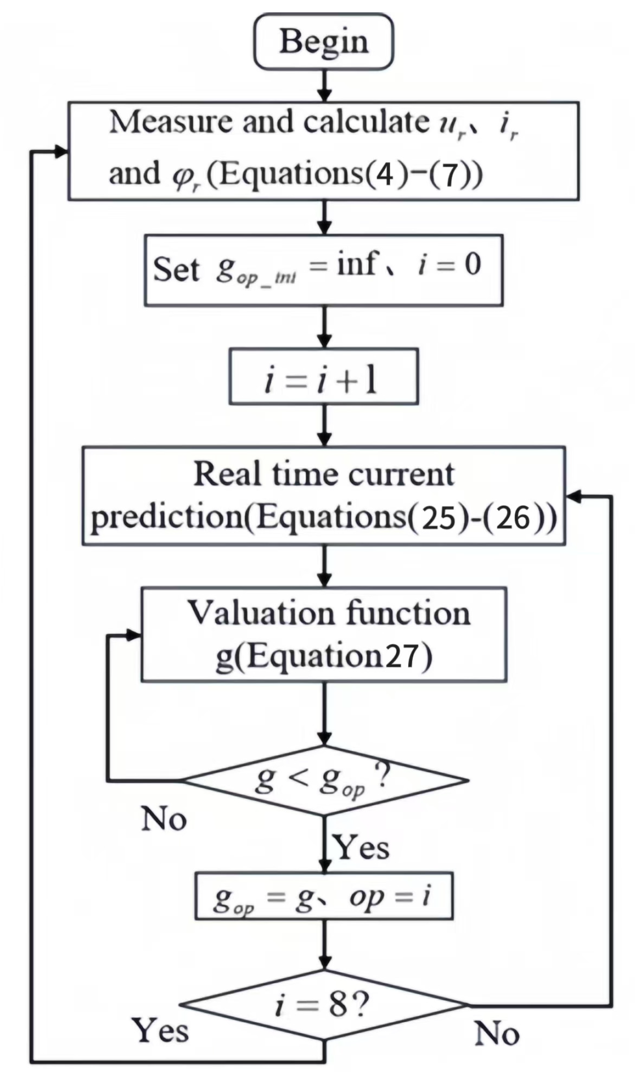
3.2.2. Current Predictive Control Algorithm

When an asymmetric fault occurs in the power grid, the generator’s stator voltage decreases, leading to the emergence of a negative-sequence component. As a result, the stator current contains both positive and negative sequence components. The stator flux consists of three components, in addition to the components corresponding to the positive and negative sequences, there is also a DC component of the stator flux formed by the inability to suddenly change due to faults. The total stator flux can be represented by the equation: φ s = ( u s R s i s ) d t . Due to the relatively slow variation in the DC component of the magnetic flux, the free component may be obtained by means of filtering the magnetic flux through a low-pass filter. During the period of asymmetric voltage drop in the power grid, transient DC flux linkage of the stator will be induced. By using a low-pass filter to filter the magnetic flux, it was found that this component is small and gradually decays, so it can be ignored. In order to facilitate comprehension, the influence of the stator transient DC flux linkage is temporally disregarded in the analysis. That is to say, solely the positive and negative sequence flux linkages and currents of the stator are taken into account.
Equation (7) can be reformulated as follow:
R r i r + L r L m 2 L s d i r d t = u r j ω r φ r
The discretization of Equation (22) involves the implementation of the forward Euler method, which replaces the difference quotient with the discrete difference value. The result should be outputted as the current control increment at time k + 1 , as demonstrated in the subsequent equation:
i r α * k + 1 = T s u r α k R r i r α k + ω r φ r β k L r L m 2 / L s + i r α k i r β * k + 1 = T s u r β k R r i r β k ω r φ r α k L r L m 2 / L s + i r β k

3.2.3. The Establishment of the Value Function

A cost function needs to be defined in the predictive control scheme, so the motor model established above is used to predict the current. The error of the reference current and the predicted current must be considered in the value function, and then the value function is established:
g = i r α r e f k + 1 i r α * k + 1 + i r β r e f k + 1 i r β * k + 1
As illustrated by Equation (24), i r α r e f k + 1 and i r β r e f k + 1 correspond to the reference values in the α β coordinate system. These reference values are derived subsequent to the coordinate transformation of the original control strategy. In this study, we sought to determine the optimal switching sequence that would yield the desired control signal for the RSC. To this end, we compared the reference value with the predicted value of the current. We then identified the switch combination that corresponded to the current vector, which resulted in the minimization of the cost function. Finally, we selected this combination as the RSC trigger pulse signal. A two-level inverter is viewed as a nonlinear discrete system that can generate eight switching states and seven different voltage vectors. as shown in the Table 1 below:
Ultimately, to realize current regulation, the switching vector that yields the minimum value of the cost function is determined and applied as the control output. The specific implementation structure of the MPCC strategy for the (RSC) is illustrated in the control block diagram presented in Figure 2, while the corresponding procedural steps are outlined in the flowchart depicted in Figure 3.

4. Simulation Verification

To validate the performance of the designed control scheme under conditions of voltage sags, a 2 MW doubly fed wind turbine is used to simulate the occurrence of symmetrical and asymmetrical faults in the power grid. As a comparison, the simulation results under the conventional control algorithm are also given in this paper. DFIG system parameters are as Table 2.
At the moment of fault detection, the excitation converter detects a voltage dip at the grid connection point. The system switches the RSC from the original PI control to a model predictive current control strategy. The PGSC adopts a traditional PI control strategy, while the SGSC employs positive–negative sequence separation control during asymmetric faults and PI control during symmetric conditions. Figure 4 illustrates the simulated waveform when the system voltage drops to 60% for a three-phase symmetrical fault, Figure 5 illustrates the simulated waveform when the system voltage drops to 60% for a single-phase ground fault, Figure 6 displays the waveform for a 70% voltage drop during a two-phase short circuit. Panels 4 (a–e) depict rotor/stator currents, grid currents/voltages, torque, and DC bus voltage in the dq frame. Figure 5 and Figure 6a–l cover key system responses, including phase-a currents, SGSC voltage/current components, grid-side current, torque, DC voltage, active power, and reactive power flow. In addition, the PI marked in the Figure represents the conventional PI control (RSC adopts the directional control based on the stator flux linkage, and SGSC adopts the T/4 positive and negative sequence voltage separation control). The MPCC represents the use of improved coordinated control (RSC uses MPCC, SGSC still uses positive and negative sequence separation control). Specifically, in Figure 4, due to a symmetrical fault, the voltage is only positive sequence. Therefore, SGSC adopts PI control instead of the T/4 delay positive and negative sequence component control.
After a three-phase fault occurs, the voltage components drop symmetrically and only have positive sequence components. When the fault occurs at 4 s, through the control of RSC, the rotor excitation voltage is properly controlled according to the degree of grid voltage drop, and the stator current of the generator shown in Figure 4b will also be reduced accordingly, so as to further limit the stator current. In the MPCC scheme without space vector control, the PWM control signal is sent directly to the RSC by means of minimization of the cost function. This enables the control of the rotor current to be directly tracked under faults, so that the rotor current fluctuation of Figure 4a is suppressed. The enhancement of the grid-side power waveforms depicted in Figure 4c–d facilitates the successful implementation of voltage dip recovery functionality for the DFIG system. At this point, as shown in Figure 4e,f, the power quality of the grid is significantly improved in contrast to traditional control methods, and the coordinated control of SGSC and RSC effectively mitigates fluctuations in electromagnetic torque and bus voltage. In Figure 4, due to a symmetrical fault, the voltage is only positive sequence. Therefore, SGSC adopts PI control instead of the T/4 delay positive and negative sequence component control. Thus, by comparing Figure 4 with Figure 5 and Figure 6, it can be observed that when the fault is removed, the switching of the control strategy in Figure 4 will cause significant voltage and current fluctuations, which cannot be avoided.
Figure 5a and Figure 6 show that the quality of the rotor current curve is stable if no fault occurs before 4 s. After the fault occurs, The rotor generates a starting current due to the negative-sequence component in the stator flux. Conventional PI control increases the rotor current to a peak of 2.1 kA at 0.076 s after a single-phase fault, and to a peak of 1.9 kA at 0.049 s after a two-phase fault. This means that under asymmetric faults, conventional PI control increases the rotor current to twice the steady-state value. However, under the improved collaborative control using MPCC, the maximum rotor current in Figure 5 and Figure 6 is around 1.1 kA. After 0.383 s of two-phase fault, the rotor current gradually decays after reaching the peak value of 1.14 kA. In the later stage of fault, it is basically between −0.89 and 0.76 kA, and compared with the fluctuation range before fault −1.0 to 1.0 kA, the exceeding limit does not exceed 24%.
As the terminal voltage drops, the stator voltage will also drop and the flux linkage will change in a corresponding manner. At this point, there is also an inrush current in the stator current, as shown in (b) of Figure 5 and Figure 6. With MPCC, the flux linkage is suppressed and the stator current amplitude is reduced. Compared to traditional PI control, MPCC is more effective in suppressing the stator and rotor currents when a fault is detected. This has the advantage that the stator can be controlled in such a way that reactive power can be sent via the rotor current after the voltage has dropped, thus providing reactive power support for the grid.
The key to fault control is suppressing the flux linkage AC component that the defect causes, since the DC component and its impact are not taken into account in the study above. Figure 5 and Figure 6’s (g) illustrate how linkage cutting produces a sizable number of double-frequency AC components in conventional PI control electromagnetic torque. To some extent, MPCC limits the electromagnetic torque variation and keeps it at a relatively constant amount by exerting an inhibitory impact. Switching between the fault algorithm and the steady-state vector control technique creates some electromagnetic oscillation, especially when the mains voltage recovers.
Regardless of the control strategy employed by the three converters during a disturbance, maintaining the stability of the DC bus voltage remains a fundamental requirement for the proper functioning of the exciter converter and the enhancement of control effectiveness. Figure 5 and Figure 6, specifically part (h), illustrate the variations in DC bus voltage under PI control and MPCC control, respectively. As demonstrated, in the absence of any fault, the DC bus voltage remains stable at approximately 1.2 kV prior to the 4-s mark. However, upon the occurrence of a fault, the energy begins to accumulate within the DC link, thereby inducing voltage fluctuations. It has been demonstrated that, among the various fault types, the voltage deviation under a two-phase short-circuit is more pronounced than that under a single-phase ground fault. The MPCC strategy has been demonstrated to effectively mitigate these oscillations and reduce harmonic distortion. This finding suggests that the MPCC approach, as implemented for the RSC in this study, exhibits superiority over the conventional PI method in preserving the stability of the DC bus voltage during disturbances, whether these disturbances involve a ground fault in one phase, a short circuit between two phases, or a balanced three-phase fault.
Throughout the fault duration, regardless of the specific control method implemented by the converter, maintaining a stable DC bus voltage—reflecting the effective regulation capability of the GSC—is a fundamental prerequisite for ensuring the reliable operation of the converter and the validity of control enhancement strategies. As indicated by the preceding analysis, the voltage deviation of the DC bus under MPCC regulation remains within a 100 V margin. The GSC output current and voltage shown in (d) and (f) of Figure 5 and Figure 6 are also within a controllable range. This guarantees the effective regulation of the GSC, while markedly improving the quality of the voltage and current waveforms at the grid interface.
During a voltage sag, the DFIG compensates by injecting reactive power into the power network, and the level of reactive support provided rises correspondingly. The proposed scheme has less electromagnetic torque oscillation at the time of fault occurrence and removal, which has less mechanical impact on the wind turbine shaft system. As depicted in (k) and (l) of Figure 5 and Figure 6, the generator only minimally takes in reactive power from the grid in the later phase. Under the traditional control, an increased demand for reactive power at the generator stator terminals can impede the restoration of voltage levels within the power grid. At 4.625 s, the fault is removed, and following a short transient response, the reactive power promptly stabilizes to its steady-state value prior to the disturbance. It can be seen from (i)–(l) of Figure 5 and Figure 6 that through the effective control of the RSC, the output power fluctuation of the generator can be quickly suppressed in a relatively stable range when a fault occurs.

5. Conclusions

This paper presents a fault-tolerant strategy for DFIG-based wind energy systems. The proposed control mode enables DFIG to smoothly achieve low-voltage ride-through under various fault conditions. A MPCC method for RSC and a positive and negative sequence delay control scheme for SGSC are designed. The effectiveness of the control strategy presented is thoroughly assessed under normal, three-phase sag, single-phase grounding, and two-phase short-circuit voltage sag conditions for the DFIG. By utilizing the approach outlined in this study, the DFIG can withstand faults and maintain a stable connection to the grid. The improved control strategy proposed in this article is mainly applied during the fault period, but there are still strong impact issues caused by control strategy switching after the fault ends. Therefore, further research is needed on collaborative control from the beginning of the fault to the stage after the fault ends.
Quantitative analysis of the conclusions:
  • Three-phase symmetrical fault: In a three-phase short-circuit fault, when the grid voltage drops to 60%, the q-axis grid-side voltage under traditional PI control reaches its peak value of 0.25 kV after 0.125 s, while the improved coordinated control stabilizes it around 0.023 kV. Additionally, the improved coordinated control reduces the electromagnetic torque fluctuation range from −0.8 to 21.6 kNm to a near-stable value. The bus voltage fluctuation range is also reduced from 1.14–1.29 kV to 1.17–1.21 kV;
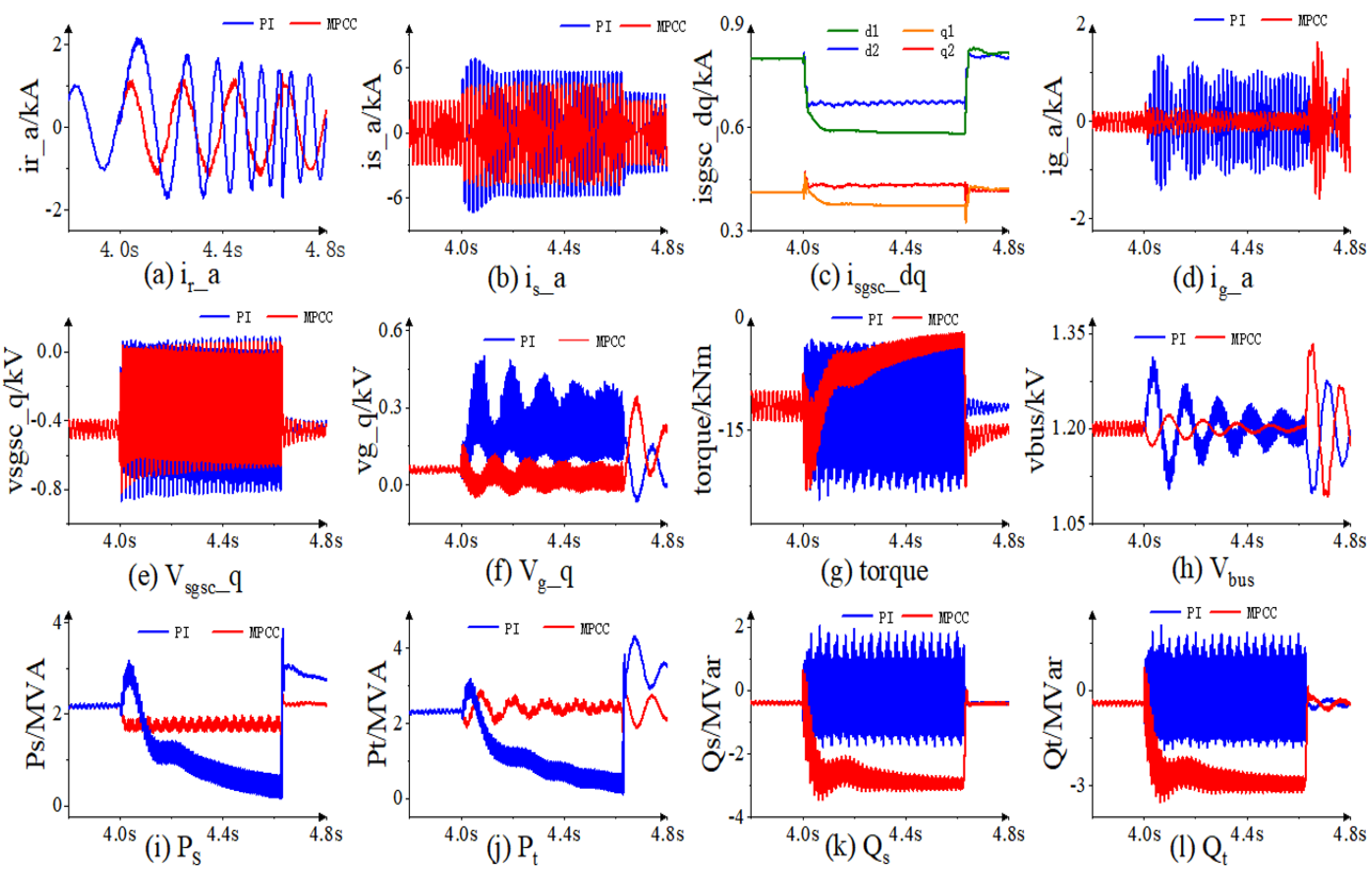
  • Single-phase grounding fault: For single-phase grounding faults, the comparison between traditional PI control and the improved coordinated control demonstrates clear performance differences. For example, in the case of a single-phase short-circuit fault, the stator current fluctuation range under traditional PI control is from −7.14 kA to 7.14 kA, while the improved coordinated control based on SGSC and RSC reduces this range to −4.3 kA to 4.3 kA, representing a reduction of approximately 40%. Furthermore, the improved coordinated control increases the minimum electromagnetic torque from −23.4 kNm to −22.1 kNm and quickly suppresses it to a relatively stable level;
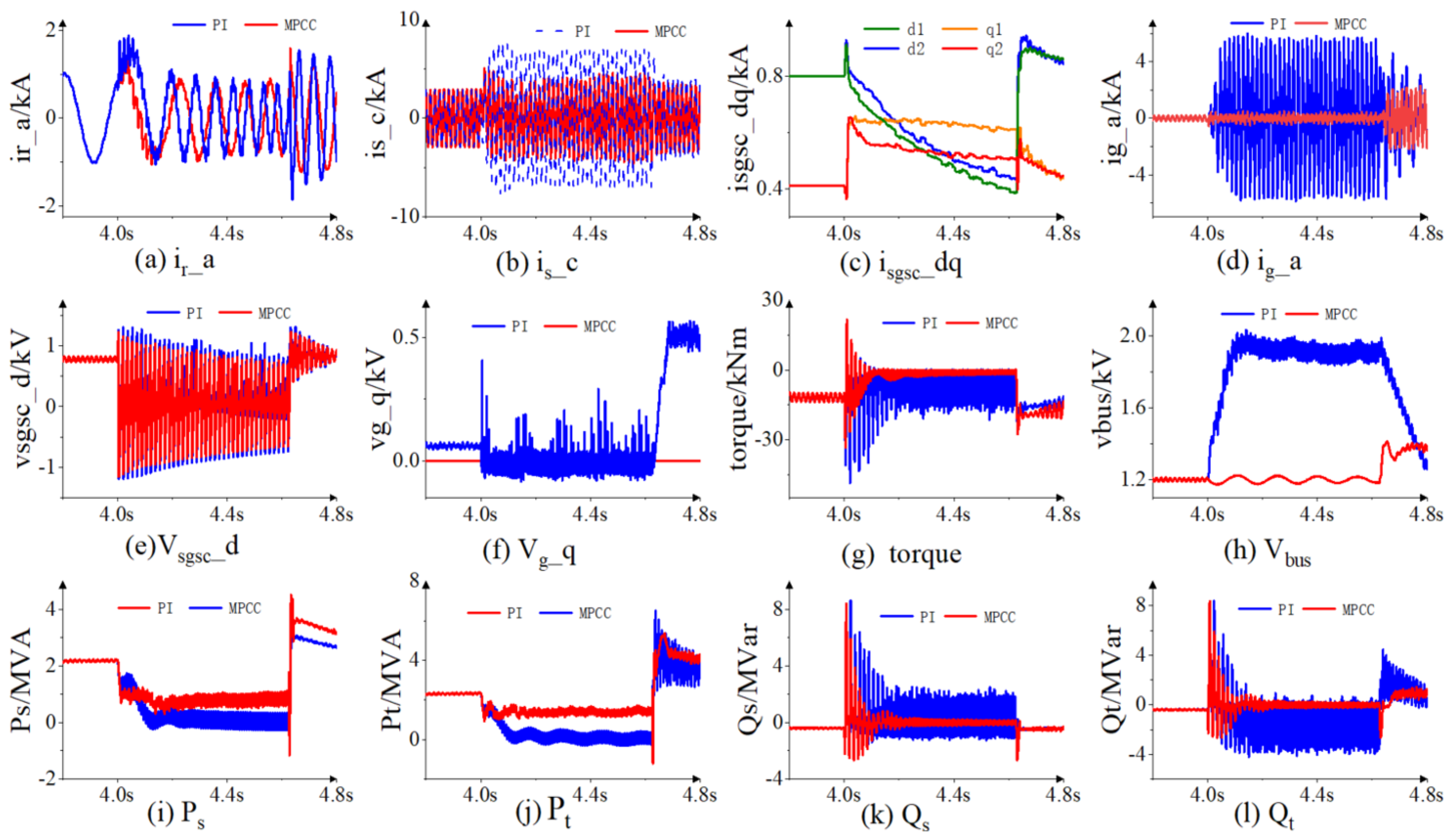
  • Two-phase short-circuit fault: For a two-phase short-circuit fault, the improved coordinated control exhibits superior performance. For instance, in a two-phase short-circuit fault, the DC-link voltage under traditional PI control peaks at 2.03 kV after 0.143 s, while the improved coordinated control limits it to between 1.17 kV and 1.26 kV. Additionally, the improved coordinated control ensures that the reactive power stabilizes after 0.21 s, with the fluctuation range being only −0.4 MVar to 0.38 MVar. The quantitative analysis demonstrates that the improved coordinated control strategy significantly enhances system stability and response speed under various fault conditions, providing more reliable low-voltage ride-through capability for DFIG wind energy systems during grid faults.

Author Contributions

Conceptualization, X.Q. and W.C.; methodology, X.Q.; software, X.Q.; validation, C.D.; formal analysis, X.Q. and Q.W.; investigation, J.Z.; resources, J.Z.; data curation, W.C.; writing—original draft preparation, W.C.; writing—review and editing, C.D.; visualization, C.D.; supervision, C.D.; project administration, Q.W. All authors have read and agreed to the published version of the manuscript.

Funding

This research received no external funding.

Data Availability Statement

The original contributions presented in the study are included in the article, further inquiries can be directed to the corresponding author.

Conflicts of Interest

Xin Qi, Jun Zhang and Quan Wang were employed by the China Electric Power Research Institute Wuhan Branch. The remaining authors declare that the research was conducted in the absence of any commercial or financial relationships that could be construed as a potential conflict of interest.

References

  1. Cheng, Q.M.; Wang, Y.J.; Cheng, Y.M.; Wei, L.; Shen, L. Coordinated control strategy of DFIG wind power system based on SGSC and PBC under unbalanced grid voltage. Acta Energiae Solaris Sin. 2021, 42, 351–358. [Google Scholar]
  2. Cheng, Q.M.; Wei, L.; Cheng, Y.M.; Wei, L.; Wang, Y.J. Coordinated control of DFIG Based on SGSC and lyapunov controller in unbalanced power grid. Electr. Mach. Control 2020, 24, 27–37. [Google Scholar]
  3. Suppioni, V.P.; Grilo, A.P.; Teixeira, J.C. Improving network voltage unbalance levels by controlling DFIG wind turbine using a dynamic voltage restorer. Int. J. Electr. Power Energy Syst. 2018, 96, 185–193. [Google Scholar] [CrossRef]
  4. Suppioni, V.P.; Grilo, A.P.; Teixeira, J.C. Control methodology for compensation of grid voltage unbalance using a series-converter scheme for the DFIG. Electr. Power Syst. Res. 2016, 133, 198–208. [Google Scholar] [CrossRef]
  5. Yao, J.; Li, H.; Chen, Z. Enhanced control of a DFIG-Based wind-power generation system with series grid-side converter under unbalanced grid voltage conditions. IEEE Trans. Power Electron. 2013, 28, 3167–3181. [Google Scholar] [CrossRef]
  6. Kang, Y.L.; Zheng, T.T.; Miao, S.H.; Liu, Z.W.; Liu, Y.L. Coordinated control strategy of series and parallel networked side converters for DFIG system under unbalanced grid voltage. Trans. Electr. Technol. 2018, 33, 193–204. [Google Scholar]
  7. Hiremath, R.; Moger, T. Grid-Connected DFIG Driven Wind System for Low Voltage Ride Through Enhancement using Neural Predictive Controller. J. Inst. Eng. India Ser. 2022, 103, 1577–1588. [Google Scholar] [CrossRef]
  8. Petersson, A. Analysis, modeling and control of doubly-fed induction generators for wind turbines. Doctoral Thesis, Chalmers University of Technology, Gothenburg, Sweden, 2005. [Google Scholar]
  9. Flannery, P.S.; Venkataramanan, G. A grid fault tolerant doubly fed induction generator wind turbine via series connected grid side converter. arXiv 2022, arXiv:2201.08879. [Google Scholar]
  10. Omar, S.; Helal, A.; Elarabawy, I. Stator voltage sensorless DFIG with low voltage ride-through capability using series and parallel grid side converters. In Proceedings of the 2016 7th International Renewable Energy Congress (IREC), Hammamet, Tunisia, 22–24 March 2016. [Google Scholar]
  11. Jahanbakhsh, B.; Xu, D. Improved low voltage ride through capability of doubly fed induction generator using series grid side converter. In Proceedings of the 7th International Power Electronics and Motion Control Conference, Harbin, China, 2–5 June 2012. [Google Scholar]
  12. Morari, M.; Lee, J.H. Model predictive control: Past, present and future. Comput. Chem. Eng. 1999, 23, 667–683. [Google Scholar] [CrossRef]
  13. Kouro, S.; Cortes, P.; Vargas, R. Model Predictive Control—A Simple and Powerful Method to Control Power Converters. IEEE Trans. Ind. Electr. 2000, 56, 1826–1838. [Google Scholar] [CrossRef]
  14. Ding, C.; Zhang, H.; Chen, Y. Research on Control Strategy of Solid State Transformer Based on Improved MPC Method. IEEE Access 2023, 11, 9431–9440. [Google Scholar] [CrossRef]
  15. Ding, C.; Chen, Y.; Nie, T. LVRT Control Strategy for Asymmetric Faults of DFIG Based on Improved MPCC Method. IEEE Access 2021, 9, 165207–165218. [Google Scholar] [CrossRef]
  16. Hu, S.J.; Meng, Y.F.; Li, F.L. AC voltage sensorless Control strategy of grid-connected inverter under unbalanced grid voltage. Trans. China Electrotech. Soc. 2017, 32, 146–152. [Google Scholar]
  17. Yao, J.; Liao, Y.; Li, H. Coordinated control of a doubly fed induction generator wind turbine with series grid-side converter under unbalanced grid voltage conditions. Electr. Mach. Control 2010, 14, 8. [Google Scholar]
  18. Liu, R.Z.; Chen, Z.; Tang, W.B. Control strategy of an LCL grid-connected Inverter with the influence of a phase-locked loop under a weak power grid. Power Syst. Prot. Control 2022, 50, 10. [Google Scholar]
  19. Makrini, A.E.; Karkri, Y.E.; Boukhriss, Y.; Markhi, H.E.; Moussaoui, H.E. LVRT Control Strategy of DFIG based Wind Turbines Combining Passive and Active Protection. Int. J. Renew. Energy Res. 2017, 7, 1258–1269. [Google Scholar]
  20. Li, B.; Zheng, D.; Li, B. Analysis of low voltage ride-through capability and optimal control strategy of doubly-fed wind farms under symmetrical fault. Prot. Control Mod. Power Syst. 2023, 8, 1–15. [Google Scholar] [CrossRef]
  21. Li, B.T.; Zheng, D.C.; Li, B.; Ji, L.; Hong, Q.T.; Meng, Q.L. Research on low voltage ride-through strategies for doubly-fed wind farms during asymmetric faults. Int. J. Electr. Power Energy Syst. 2024, 160, 110138. [Google Scholar]
  22. Cheng, X.K.; Sun, X.D.; Chai, J.Y.; Liu, H.; Song, P. Virtual synchronous control strategy for doubly-fed induction generator under asymmetrical gris faults. Autom. Electr. Power Syst. 2018, 42, 120–126. [Google Scholar]
  23. Lin, R.X.; Ma, X.Y.; Chang, X.Q.; Xu, L.; Ding, L.J.; Yang, H.G. Analysis of DFIG rotor current considering chopper protection under asymmetrical grid voltage sags. Proc. CSU-EPSA 2019, 31, 106–117. [Google Scholar]
Figure 1. DFIG topology with SGSC and equivalent circuit. (a) DFIG topology with SGSC. (b) Equivalent circuit of the series grid-side converter in the synchronously rotating reference frame. (c) Equivalent circuit of the dc-link.
Energies 18 02537 g001
Figure 2. DFIG topology with SGSC.
Energies 18 02537 g002
Figure 3. Model predicts the current control flow.
Energies 18 02537 g003
Figure 4. Comparison of LVRT performance between MPCC and PI for three-phase short-circuit fault.
Energies 18 02537 g004
Figure 5. Comparison of LVRT performance between MPCC and PI for single-phase short-circuit fault.
Energies 18 02537 g005
Figure 6. Comparison of LVRT performance between MPCC and PI for two-phase short-circuit fault.
Energies 18 02537 g006
Table 1. Switch state and voltage vector.
SaSbScVoltage Vector V
000 V 0 = 0
100 V 1 = 2 3 V d c
110 V 2 = 1 3 V d c + j 3 3 V d c
010 V 3 = 1 3 V d c + j 3 3 V d c
011 V 4 = 2 3 V d c
001 V 5 = 1 3 V d c j 3 3 V d c
101 V 6 = 1 3 V d c j 3 3 V d c
111 V 7 = 0
Table 2. Parameters of DFIG.
ParameterNumerical Value
Stator and rotor mutual inductance (mH)2.5
Rotor leakage inductance (mH)0.087
Stator leakage inductance (mH)0.087
DC bus voltage reference value (kV)1.2
Rated Capacity (MW)2
Rated voltage (kV)0.69
Stator resistance (mΩ)2.6
Rotor resistance (mΩ)2.9
SGSC series transformer ratio2:1
Capacity of the SGSC (MW)2
Note: Data are collected from [15] according to the specific parameter.
Disclaimer/Publisher’s Note: The statements, opinions and data contained in all publications are solely those of the individual author(s) and contributor(s) and not of MDPI and/or the editor(s). MDPI and/or the editor(s) disclaim responsibility for any injury to people or property resulting from any ideas, methods, instructions or products referred to in the content.

