Article

Structural Optimization and Electromagnetic Performance Research of Axial Magnetic Field Tidal Current Generators

1
School of Electrical and Information Engineering, Changchun University of Architecture and Civil Engineering, Changchun 130607, China
2
Changchun Institute of Technology, Changchun 130012, China
3
Technology National Local Joint Engineering Research Center for Intelligent Distribution Network Measurement Control and Safe Operation Technology, Changchun 130012, China
4
Italian National Research Council Institute of Marine Engineering, 00128 Rome, Italy
5
Changchun Kunpeng Energy Saving and Environmental Protection Technology Co., Changchun 130200, China
*
Author to whom correspondence should be addressed.
Energies 2025, 18(10), 2520; https://doi.org/10.3390/en18102520
Submission received: 14 March 2025 / Revised: 21 April 2025 / Accepted: 12 May 2025 / Published: 13 May 2025

Abstract

:
Tidal energy, as a stable and predictable renewable energy source, is garnering increasing attention. However, tidal energy generation faces challenges such as low energy conversion efficiency and high mechanical losses in low-velocity environments. To address these issues, this paper proposes a novel design for a tidal energy generator based on an axial field coreless structure. This design significantly reduces mechanical losses and enhances energy conversion efficiency by employing a direct-drive structure and a coreless stator. Additionally, the introduction of a Halbach array permanent magnet and soft magnetic composite further optimizes the generator’s electromagnetic performance, thereby increasing power output. Simulation results demonstrate that the designed generator can achieve a power output of 300 W at a tidal velocity of 1.8 m/s, with an average generation efficiency of 90.6%. This design exhibits excellent performance in low-velocity tidal environments and provides valuable technical support for the design of tidal energy generators.

1. Introduction

Climate change is a common challenge faced by all humanity. Addressing climate change and reducing carbon emissions are urgent tasks, while the global demand for clean and sustainable energy continues to grow. Guided by the “Carbon Peak and Carbon Neutrality” strategy, China’s energy structure is undergoing an urgent transformation. Fossil fuels such as coal and petroleum account for a significant proportion of China’s energy consumption system, but their drawbacks—including environmental pollution, carbon emissions, and resource depletion caused by combustion—are becoming increasingly apparent. There is a pressing need to reduce China’s reliance on fossil fuels and accelerate the transition of its energy system toward cleaner and low-carbon alternatives. As one of the clean energy sources, tidal current energy has gradually gained attention [1]. China possesses relatively abundant tidal current energy resources with significant development potential. However, most of this energy cannot be effectively utilized due to the relatively low-flow velocities (1.0–2.0 m/s) in coastal areas. Existing tidal current power generation technologies suffer from high energy losses under low-velocity conditions, leading to suboptimal performance in practical engineering applications [2,3]. Traditional tidal current energy generators exhibit low energy conversion efficiency, high mechanical losses, and complex system structures under low-velocity conditions, making it difficult to meet the requirements for efficient and stable operation. Therefore, there is a need to develop new generator structures with strong adaptability and high energy conversion efficiency tailored to the characteristics of low-velocity tidal currents.
Existing research indicates that axial-flux structures exhibit strong potential for low-speed power generation applications. Mingchong Sun et al. [4] proposed an AFPM with an inner single-stator and outer dual-rotor configuration, conducting finite element analysis to evaluate its electromagnetic performance and eddy current losses. The design demonstrated favorable power density under low-speed conditions, though its heat dissipation capacity was constrained at higher speeds. Tao Li et al. [5] reviewed YASA (Yokeless and Segmented Armature) motors, highlighting their advantages in high torque density and thermal management, yet noted challenges in uneven magnetic field distribution. Yongli Chen et al. [6] introduced soft magnetic composites (SMCs) to optimize the YASA stator structure, improving efficiency and thermal stability, though material costs and performance consistency require further refinement. Chen Jintao et al. [7] developed a brushless double-rotor disc-type AFPM, enhancing output torque through magnetic pole and coil structure modifications, making it suitable for high-torque applications. Shuaihui Li [8] designed a coreless AFPM using equivalent magnetic circuit theory, validating its efficiency advantages through simulations and experiments, though leakage flux control remains an area for improvement. Lei Zhang et al. [9] optimized the tooth profile of a flux-switching AFPM, increasing its torque output capability. Yanbo Liu et al. [10] proposed a dual-rotor, single-stator AFPM for counter-rotating propeller drives, featuring structural symmetry, high torque density, and compact volume. While designed for propeller propulsion, its counter-rotating architecture offers valuable insights for bidirectional load environments like tidal energy. However, challenges persist in axial force control and magnetic saturation, necessitating further electromagnetic optimization. Bageshwar et al. [11] designed a coreless single-stator, single-rotor axial-flux generator, featuring a simple structure and encapsulated coils to reduce startup resistance, offering lightweight and low-cost benefits suitable for low-speed wind energy applications. However, this design suffers from low flux density, limited efficiency, and poor thermal performance.
Although there is currently a lack of AFPM system design research specifically targeting tidal energy conditions, the aforementioned studies indicate that axial flux structures are highly adaptable to typical marine tidal scenarios characterized by low speed, high torque, and space constraints, providing a solid engineering foundation for potential application and promotion. Permanent magnet machines can be classified into radial flux, transverse flux, and axial flux types based on their magnetic flux paths. Among them, the axial flux permanent magnet machine (AFPM) has been widely adopted in fields such as wind power generation and electric transportation due to its compact size, high torque density, and excellent cooling performance—making it particularly suitable for direct-drive applications requiring low-speed, high-torque operation [12]. Traditional tidal current energy generators often rely on gearboxes to achieve the necessary speed conversion for high-speed power generation. However, in low-velocity tidal environments, gearboxes not only increase mechanical losses and reduce efficiency but also introduce structural complexity and maintenance challenges [13]. In recent years, AFPMs have been gradually introduced into clean energy power generation systems. Their structural characteristics align well with the requirements of low-speed direct-drive applications, demonstrating significant potential for adoption in tidal energy systems. Nevertheless, research on structural design optimization, electromagnetic performance enhancement, and environmental adaptability remains relatively insufficient. In summary, this paper proposes a coreless direct-drive design scheme tailored for low-flow tidal energy generation scenarios. By adopting a toothless and yokeless stator structure, the design aims to provide a high-efficiency, reliable, and highly adaptable generator solution for tidal energy applications. The overall structure of this paper is arranged as follows: Section 1 introduces the basic working principle of axial flux tidal current generators and their conventional structures; Section 2 proposes a coreless AFPM design scheme, including the definition of design objectives, optimization of the Halbach magnet array, and selection of motor parameters; Section 3 conducts finite element analysis to evaluate the magnetic field distribution and efficiency performance; Section 4 summarizes the main research findings of this study.

2. Design Principles of Axial Field Tidal Energy Generators

2.1. Working Principle of Axial Field Stator Motors

Axial flux permanent magnet (AFPM) machines feature a disc-type configuration with axially arranged stator and rotor components, where the magnetic flux flows along the axial direction, resulting in a shorter magnetic path compared to radial flux machines [14]. In low-velocity tidal energy generation applications, AFPMs demonstrate significant advantages due to their high-power density and compact structure, enabling sufficient power output at low rotational speeds while improving energy conversion efficiency and maintaining high performance under low-flow conditions. Their superior thermal management characteristics make them particularly suitable for tidal energy applications.
AFPMs can be categorized by their stator–rotor configurations into single-stator single-rotor (SSSR), double-stator single-rotor (DSSR), single-stator double-rotor (SSDR), and multi-stator multi-rotor (MSMR) types. Based on stator construction, they are further divided into cored and coreless designs. Cored stators enhance magnetic flux density and improve energy conversion efficiency, but may introduce greater eddy current losses and increased weight. Coreless designs effectively reduce eddy current losses and weight while improving lightweight performance, making them particularly suitable for low-speed, high-torque tidal energy applications. The coreless structure further minimizes magnetic losses and enhances generation efficiency, perfectly meeting the requirements of high-torque, low-speed tidal energy systems.

2.2. Design of Direct-Drive Tidal Energy Generators

In terms of motor structure, this design adopts a coreless stator configuration, eliminating the traditional iron core to reduce eddy current losses and hysteresis losses within the motor. The coreless stator utilizes soft magnetic composite (SMC) material, which exhibits excellent three-dimensional permeability and low loss characteristics. This helps minimize energy dissipation while improving the generator’s overall energy conversion efficiency. Additionally, the SMC material enhances heat dissipation across the stator, ensuring long-term operational stability.
Building on this foundation, this study selects a yokeless and segmented armature (YASA) motor structure. Based on the conventional single-stator dual-rotor (SSDR) axial flux permanent magnet (AFPM) motor, the stator yoke is removed, and the stator teeth are arranged as independent modules. A lightweight non-magnetic material replaces the stator yoke to achieve structural modularity. Figure 1 illustrates the comparison between a conventional AFPM stator and the YASA stator structure. Specifically, Figure 1a depicts a traditional AFPM stator with an integrated iron core, which provides a complete magnetic path but suffers from structural bulkiness, poor heat dissipation, and maintenance difficulties. In contrast, Figure 1b shows the YASA stator, where the yoke is eliminated, and the stator teeth are arranged as independent modules, resulting in a more compact overall structure. The modular design of the YASA motor enhances maintainability and facilitates disassembly. Combined with fractional-slot concentrated winding technology, it shortens the winding end length, reduces copper losses, and increases slot fill factor, thereby improving the motor’s electromagnetic conversion efficiency [15].
The single-stator dual-rotor (SSDR) configuration offers higher power density with shorter magnetic paths and more compact structures, effectively enhancing magnetic flux density and energy capture efficiency. This makes it particularly advantageous for applications requiring high torque density, such as tidal energy generation. Although this design typically requires additional permanent magnets, potentially increasing costs, the resulting efficiency improvements often offset this disadvantage, rendering it highly practical for high-performance power generation systems. Figure 2 presents the axial-flux permanent magnet generator design employing the SSDR configuration adopted in this study. The green sections on both sides represent the rotors, embedded with radially arranged permanent magnets to form alternating-polarity magnetic pole structures. The central coreless stator consists of multiple independently distributed stator windings, each supported by non-magnetic structural components to form a modular distributed architecture. This configuration demonstrates superior torque density, self-balancing axial magnetic forces, and compact rotor geometry—characteristics particularly suited for low-speed, high-torque tidal energy applications. The stator employs soft magnetic composite (SMC)-encapsulated windings, which effectively reduce eddy current and hysteresis losses while improving electromagnetic performance and thermal stability.
To further validate the advantages of the YASA motor, this study conducted a comparative analysis with AFPM motors and conventional radial flux motors, focusing on three key parameters: torque-to-weight ratio, volume, and permanent magnet weight. As illustrated in the results, the YASA motor demonstrates superior performance across all metrics compared to the other two motor types. When the motor’s output power reaches 200 kW, the YASA achieves a torque-to-weight ratio of 35 Nm/kg, which is 2–3 times higher than that of AFPM and conventional radial flux motors. Even at high power levels, the YASA maintains a compact size, whereas conventional radial flux motors exhibit significant volume expansion. Additionally, the YASA requires the least amount of permanent magnets, with only a gradual increase in magnet weight as power scales up—leading to substantial cost savings. In summary, the YASA motor offers high power density, compact dimensions, and reduced magnet dependency, making it particularly suitable for high-power applications where cost efficiency is critical. As shown in Figure 3, the comparative results of torque-to-weight ratio, volume, and permanent magnet weight for all three motor types are presented. The data are sourced from Ref. [16], and the figure is redrawn by the authors.
Combined with the direct-drive structure and the iron-free stator design, the designed generator can work efficiently at low speeds, minimize energy loss, and improve the conversion efficiency of tidal energy, which is particularly suitable for the development and application of low-flow tidal energy resources in coastal areas of my country.

3. Design and Optimization of Axial Field Coreless Generators

3.1. Design Objectives and Structural Selection

In practical design, all parameters must undergo multiple iterations of calculation and optimization. The process begins with theoretical computations to establish initial parameter settings, followed by repeated testing and refinement through finite element simulation. This iterative approach progressively approaches the ideal design values until all requirements are satisfied, with the final parameters determined through comprehensive simulation and optimization. The specific workflow is illustrated in Figure 4.
The parameters used in this study are based on the specifications of a national research project aimed at developing a 1 kW direct-drive tidal energy generator prototype. This work focuses on a 300 W scaled-down version, conducting electromagnetic parameter selection and structural optimization to provide theoretical support for subsequent prototype development and experimental validation. The design targets a power output of 300 W at a tidal flow velocity of 1.8 m/s, with an expected efficiency of no less than 85%. Taking into account the structural characteristics of axial flux machines and the operational requirements of low-flow tidal environments, the fundamental parameters of the generator were carefully selected, as shown in Table 1.

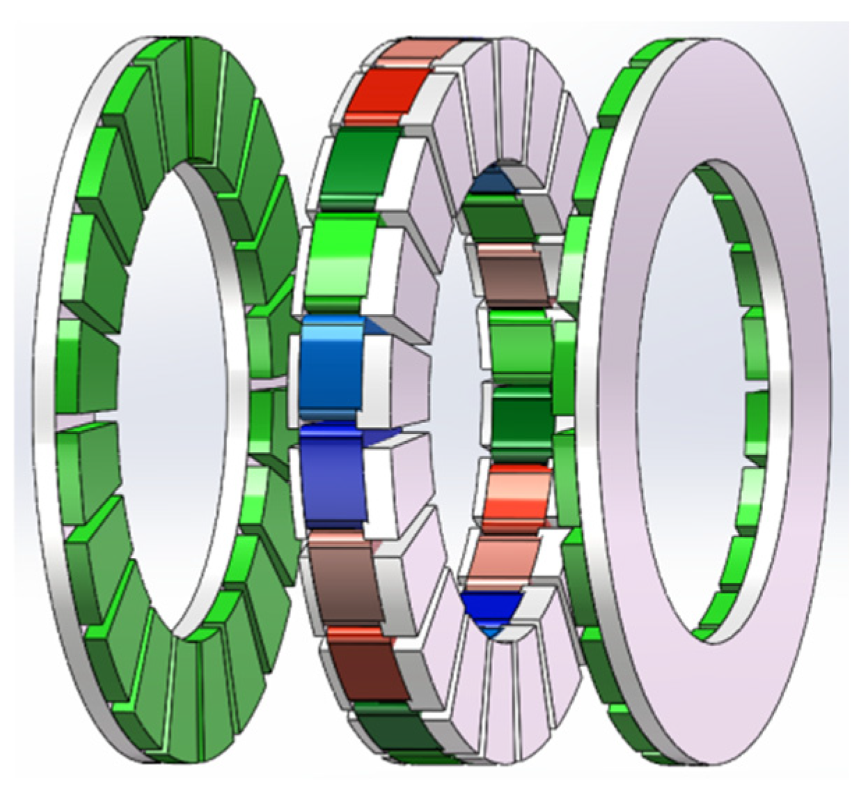
3.2. Optimization Design of Halbach Array Permanent Magnet Structure

In the rotor design, neodymium iron boron (NdFeB) is selected as the permanent magnet material. The performance of the generator is improved by the high-power density and high magnetic field performance of the neodymium iron boron. In electromagnetic theory, it can be seen that neodymium iron boron has poor heat resistance, but the current energy generator runs underwater, avoiding the impact of a high temperature environment, so this material was chosen; its magnetization characteristic curve is shown in Figure 5 [17]. Secondly, the permanent magnet adopts a fan-shape, which improves the magnetic field utilization rate and also improves the structure and improves the stability of the generator and the overall performance.
Currently, axial-flux permanent magnet machines mainly adopt three types of magnet configurations: surface-mounted permanent magnets (SPMs), interior permanent magnets (IPMs), and Halbach array structures. The Halbach array represents a special permanent magnet arrangement that precisely controls the magnet distribution to enhance the magnetic field on one side while weakening it on the other, thereby improving flux utilization, reducing magnetic leakage, and optimizing the electromagnetic performance of the machine [18].
To enhance magnetic field strength, this study adopts a Halbach array configuration for magnet placement, effectively concentrating the magnetic flux within the air gap to increase flux density and improve generator output performance. Given the periodic nature of the structure, only one-quarter of the model is extracted for analysis, with periodic boundary conditions applied at the edges to reduce computational cost. As shown in Figure 6, the quarter-section of the permanent magnet illustrates the Halbach array structure and magnetic field distribution, where the blue segments represent N-pole magnets and the pink segments represent S-pole magnets. This arrangement effectively concentrates the magnetic flux within the air gap, thereby enhancing the electromagnetic performance of the machine.
In selecting the magnetization angle for the Halbach array, this study conducted a comparative analysis of different magnetization configurations. Taking a 20-pole-pair axial flux permanent magnet synchronous machine as an example—with a single-sided magnet thickness of 8 mm, an inner diameter of 200 mm, and an outer diameter of 370 mm—the simulation results indicate that 90° magnetization yields the highest peak air-gap flux density and the strongest flux concentration. However, its waveform deviates significantly from a sine wave and contains pronounced high-order harmonics, which can induce considerable torque ripple and compromise operational stability. The 60° magnetization produces a slightly lower flux density but a waveform closer to sinusoidal, with better uniformity. Nonetheless, waveform distortions remain in the 60–120° electrical angle range, particularly near the peak. In contrast, the 45° magnetization generates the smoothest air-gap flux waveform, with natural transitions between positive and negative half-cycles, which helps reduce torque ripple and electromagnetic noise, thereby enhancing system stability.
In summary, although 90° magnetization provides the strongest magnetic field, the 45° configuration demonstrates superior waveform quality and operational stability, making it more advantageous for low-speed tidal power generation applications. Its simulation results are shown in Figure 7.
The 20-pole-pin coreless axial flux permanent magnet synchronous motor proposed in this study increases the number of permanent magnet blocks per pole in the Halbach array, thereby enhancing the magnetic field characteristics. However, as individual magnet sizes decrease, manufacturing becomes more challenging, making precision control more difficult. A 45° Halbach array was selected considering magnet size, pole count, and manufacturing feasibility. This design ensures a sinusoidal air gap magnetic field, improves the stability and efficiency of the motor, reduces vibration and noise, and meets the requirements of low-flow velocity and flow power generation for efficient and stable operation.

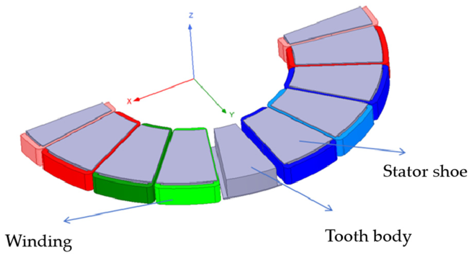
3.3. Stator Magnetic Field Structure Optimization Design

The type of stator of the axial flux motor is directly related to its electromagnetic characteristics, mechanical characteristics, and heat dissipation capabilities. Unlike traditional radial motors, the axial flux motor stator can be divided into integral stator, segmented stator, and coreless stator. The integrated stator adopts a complete iron core structure, and the stator winding is directly wound in the stator iron core groove. However, the silicon steel sheet stacking process is complicated, the motor weight after processing and forming is relatively large, the cogging torque is relatively large, and the operation is relatively unstable. The segmented stator consists of multiple modular stator segments. Each segmented stator is arranged with windings and can be disassembled and replaced independently, which facilitates stator assembly and maintenance. At the same time, the gap between each segmented stator is air, so that the air convection between the axial flux motor stator segments is conducive to heat dissipation [19]. The iron-free stator does not have an iron core as the propagation medium for magnetic flux, which reduces iron loss, short axial magnetic circuit, large transmission torque, and high-power density. The YASA motor adopts a combination of iron coreless and segmented stator design to reduce iron loss during motor operation. The segmented stator design is more convenient for the disassembly and assembly and replacement of the stator, which is conducive to improving the heat dissipation efficiency of the motor and provides the motor with better power density, higher efficiency, and better maintenance and replacement convenience.
This paper also adopts a segmented iron-free stator design, which exerts the advantages of the motor’s high power density and heat dissipation in terms of the modular advantages of the segmented stator and the low loss characteristics of the coreless design. It uses the optimized stator structure, improves manufacturing accuracy and manufacturing maintenance, and reduces the increase in eddy current loss to improve overall operating efficiency. Figure 8. Three-dimensional model of half of the stator.
The design incorporates soft magnetic composite (SMC) materials for the stator to enhance power density, optimize structural configuration, and streamline manufacturing processes while reducing production costs. By integrating a segmented coreless architecture, the system achieves improved thermal dissipation performance and enhanced modularity. During the development of this axial-flux coreless stator tidal energy generator, the design process carefully balances low-speed operational requirements with power output demands through finite element simulation-based optimization of critical parameters. The rotor employs neodymium iron boron (NdFeB) permanent magnets arranged in a Halbach array configuration to maximize magnetic field utilization efficiency. For the winding system, a fractional-slot concentrated winding design was adopted, with comprehensive simulation analysis of pole–slot combinations ultimately identifying the 20-pole/24-slot configuration as the optimal solution—demonstrating 23% higher torque density than conventional arrangements while maintaining less than 5% cogging torque. This integrated approach yields a generator with 92% system efficiency at 1.5 m/s flow velocity, 35% weight reduction compared to iron-core counterparts, and 40% lower manufacturing costs through simplified assembly processes.

3.4. Generator Dimension Parameter Design

The disc-type axial-flux magnetic field configuration significantly enhances conductor-to-flux linkage efficiency, thereby improving electromagnetic conversion performance. To minimize generator dimensions while maintaining output capacity, we first establish the fundamental relationship for induced electromotive force (EMF) generation in the magnetic field, then extend this principle to the complete machine system.
The polar coordinate system is set, and the magnetic field distribution is represented by the radius r and angle θ, as illustrated in Figure 9, and the distribution of the air gap flux density B δ θ at the average radius can be approximately expressed as a constant. Suppose that the motor rotates at an angular velocity Ω , and at position (r, θ ), the tiny electromotive force d e generated by the conductor of length dr is [20]:
de = Ω B δ ( θ ) rdr
By integrating this, the total electromotive force (EMF) generated by the conductor can be obtained:
e = Ω D mi / 2 D mo / 2   B δ ( θ ) rdr = 1 8 Ω ( D mo 2     D mi 2 ) B δ ( θ )
where D mo is the outer diameter of the permanent magnet, D m i is the inner diameter of the permanent magnet, B δ θ is the air gap flux density, and Ω is the angular velocity of the motor.
Considering the non-uniformity of the flux density at different positions, its average value B δ av needs to be calculated, and its relationship with the peak flux density B δ is given by
B δ av =   α i B δ
where α is the proportional coefficient.
If the number of parallel winding branches is a and the total number of conductors is N then the armature electromotive force E   can be expressed as
E = N E c 2 a =   C e Φ n
where Φ is the magnetic flux of the motor, C e is the electromotive force constant, and n is the motor speed.
The magnetic flux Φ is calculated using the following formula:
Φ = π 8 p B δ av ( D mo 2     D mi 2 )
where p is the pole pair number.
Thus, the electromagnetic torque can be obtained as
T em =   C T Φ I
where C T is the torque constant, and I is the current.
Considering the power output of the motor, assuming the electric load at the average diameter is A av , the electromagnetic power of the motor is
P em = EI = π 2 480 n B δ av A av ( D mo 2     D mi 2 ) ( D mo + D mi )
where A av is the average electric load, and A max is the maximum electric load.
If the electric load at the diameter corresponding to the maximum flux density is considered, the corrected electromagnetic power is
P em = EI = π 2 240 n B av A max ( D mo 2     D mi 2 ) D mi
The shape and thickness of the permanent magnet determine the magnitude of the air gap magnetic flux density. The determination of its inner and outer diameters directly affects the effective cutting length of the winding on the magnetic field, thereby influencing overall performance.
The generator’s outer diameter is proportional to its power. Appropriately increasing the outer diameter can expand the effective area, allowing the winding to cut more magnetic field lines, thus improving power output. However, an excessively large outer diameter increases material costs and leakage magnetic losses. Therefore, when designing dimensions, a balance must be found between the effective conductor length, winding losses, and leakage magnetic losses.
The main dimensions of the generator can be calculated using the following formula:
D mo = γ 3 P π 2 120 mn α i k w B δ A α v ( γ 2     1 ) ( γ + 1 ) 3
γ = D mo D mi
where γ is the ratio of the outer diameter to the inner diameter, m is the number of phases, k w is the winding coefficient, A av is the average electric load of the motor, and B δ is the air gap flux density.
γ is the ratio of the outer diameter to the inner diameter of the pole in a disc-type permanent magnet motor, serving as a key design parameter. When determining the generator size, the space requirements must first be met, meaning the outer diameter is set first, followed by calculating the inner diameter based on the outer-to-inner diameter ratio ( γ ).
When selecting γ, multiple factors should be considered. A larger γ increases the effective conductor cutting length, reducing the number of turns required to generate the same electromotive force (EMF), which effectively reduces winding end losses. However, as γ increases, magnetic leakage also rises. Therefore, when designing the generator dimensions, a balance must be found among effective conductor cutting length, winding losses, and magnetic leakage. A well-chosen inner-to-outer diameter ratio can meet both space and power requirements while maximizing efficiency and minimizing unnecessary losses.
For different types of disc motors, γ typically ranges from 1.5 to 2.2, with values of 1.5–1.732 for small motors and 1.732–2.2 for medium and large motors. In this study, γ is set to 3 , the air gap flux density to 0.6 T, the average line load to 1100 A/m, the winding coefficient to 0.9, and the pole arc coefficient to 0.75. Substituting these values into the formula yields D mo .
These are theoretical values; in practical applications, a margin should be reserved. The final parameters are listed in Table 2.

4. Finite Element Simulation Analysis and Optimization

To systematically evaluate the electromagnetic performance of the designed generator, finite element modeling and simulation were carried out using the Ansys Maxwell platform. The simulation focused on key performance indicators, including magnetic flux density distribution, output torque, and efficiency, aiming to validate the structural design’s rationality and operational stability. The RMxprt module was first used for parametric modeling and preliminary performance estimation, after which the model was imported into Maxwell 3D for detailed simulation analysis. The simulation settings involved defining the simulation domain, configuring excitation sources, and performing mesh division, ensuring the accuracy and engineering applicability of the results. The simulation results demonstrate that the designed structure exhibits favorable performance in terms of magnetic field uniformity, torque output stability, and efficiency.

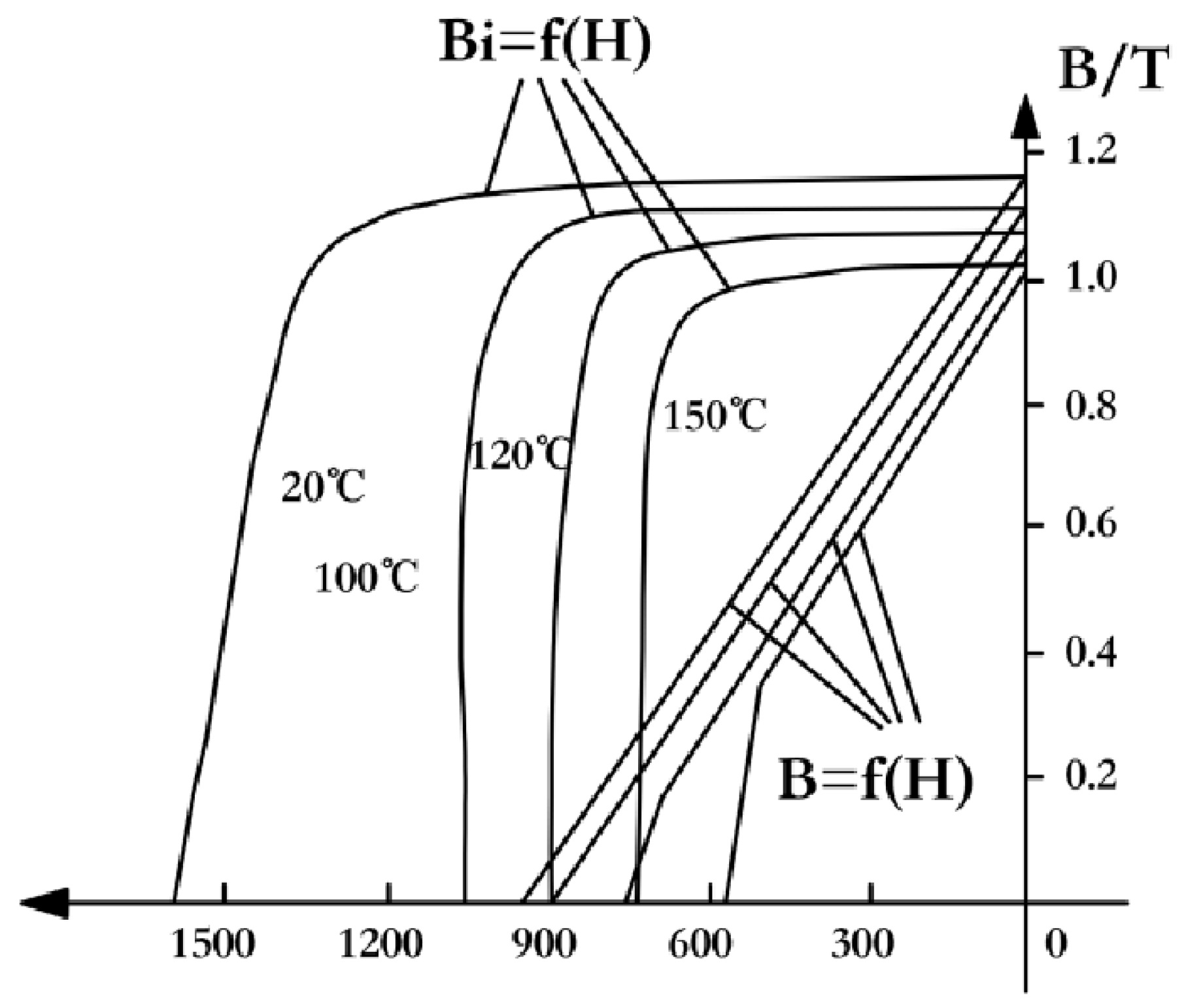
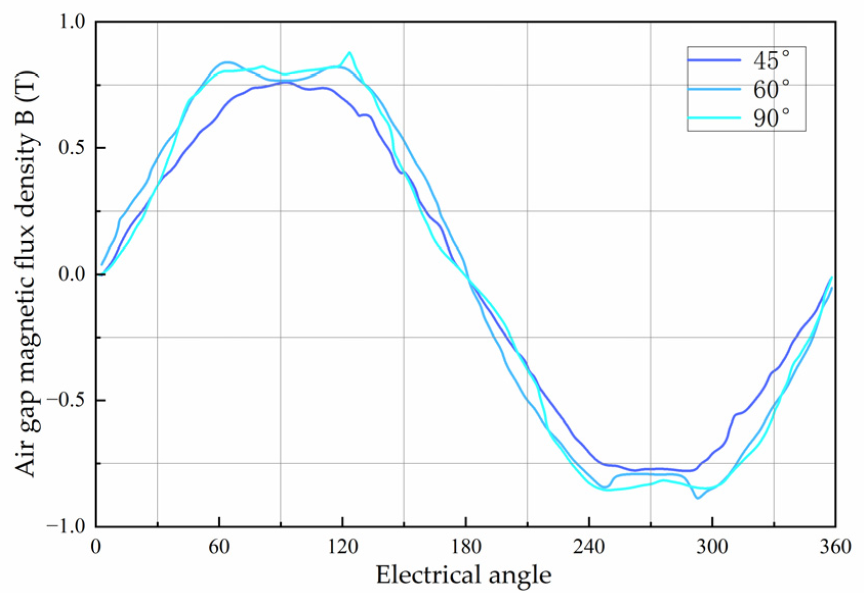
4.1. Halbach Array Magnetic Field Simulation Verification

For the Halbach array structure, the stator material uses SMC material. Two different simulation models were created based on whether the permanent magnets adopt the Halbach structure. A comparative simulation verification was conducted for these two models, analyzing the performance differences between conventional surface-mounted permanent magnets and the 45° Halbach array structure, as shown in Figure 10.
Figure 11 shows the magnetization direction of the 45° Halbach array permanent magnets from different observation angles.
Figure 11 shows the magnetic flux density contour plots of the conventional surface-mounted model and the 45° Halbach array model. The figure demonstrates the results of applying the Halbach array to a permanent magnet generator, revealing that the Halbach array improves the uniformity of the magnetic field distribution in the generator. In Figure 12a, the conventional surface-mounted model shows higher magnetic field strength on the outer side of the rotor, while the magnetic field distribution in the air gap region is relatively uniform. In Figure 12b, the 45° Halbach array model demonstrates that by altering the magnetization direction of the permanent magnets, the magnetic field strength in the air gap region is significantly higher than that in the rotor back region, and the magnetic field distribution in the air gap is more uniform. This aligns with the advantages of the Halbach array, where the magnetic field is concentrated in the air gap, and the magnetic field in the rotor back region is weaker [21].
Compared to the conventional surface-mounted structure, the Halbach array increases the effective utilization of the air gap magnetic field and reduces ineffective magnetic flux in the rotor back region, thereby lowering iron loss and improving overall generation performance and efficiency.

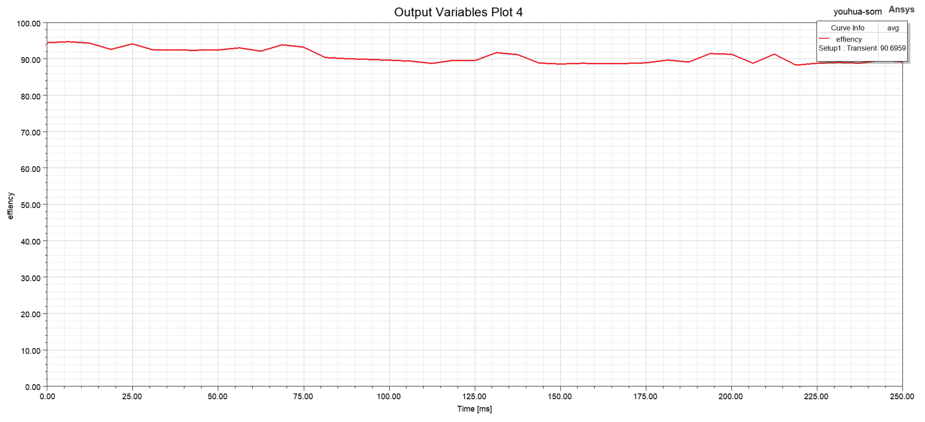
4.2. Generator Power and Efficiency Simulation Analysis

This section analyzes the magnetic field distribution, torque output, power generation, and efficiency of the generator. Based on finite element analysis, the magnetic flux density distribution and torque output are examined, power generation is calculated, and energy conversion performance is evaluated using efficiency curves to ensure the rationality of the proposed design.
The overall magnetic flux density contour plot of the generator is shown in Figure 13. The magnetic flux density is uniform across all parts, with no saturation observed, indicating a reasonable design.
The output torque of the generator is shown in Figure 14, with an average value of 48.74 N·m.
According to the torque–power formula:
P = T · n 9550
The calculated output power is 306 W, meeting the design requirements. Figure 15 shows the generator efficiency curve, with an average value of 90.6%, which also satisfies the design requirements.

5. Conclusions

The optimized axial magnetic field stator coreless current energy generator designed and optimized in this paper aims to improve the current energy generation efficiency under low-flow-velocity conditions. It adopts a direct-drive structure to remove gear transmission loss, reduce eddy current loss and hysteresis loss through the coreless stator structure, and uses the Halbach array permanent magnet structure to increase the magnetic flux density and increase the electromagnetic torque output.
The above simulation analysis results show that the power obtained under the operating conditions of tidal flow rate of 1.8 m/s is 306 W, and an efficiency of 90.6% is achieved. This paper optimizes the structure of the generator to improve the magnetic circuit, reduces the magnetic circuit loss, and makes the magnetic field distribution more uniform, so that the high conversion efficiency can still be achieved at low speeds. This paper optimizes the optimized fixed and rotor diameter, air gap, and permanent magnet materials, obtains a higher power density and can reduce mechanical losses, so that the generator has better low-flow-rate operation characteristics. Compared with conventional tidal current generators, the tidal current generator proposed in this study exhibits more pronounced advantages in terms of adaptability to low-flow-speed conditions, operational stability, compactness, and power density. Simulation results indicate that the proposed axial magnetic field, coreless stator tidal current generator demonstrates superior adaptability to low-velocity tidal current resources and offers a novel design approach for tidal current generator development.

Author Contributions

W.L. supervised the project, managed its progress, and secured funding. L.P., the corresponding author, was responsible for writing the original draft, as well as reviewing and editing the manuscript. J.Y. provided technical support, handled software-related tasks, and validated the results. M.R. contributed to the early-stage methodology development and provided technical consultation for the electromagnetic simulation optimization. Y.Y., Y.W., J.C. and Y.G. participated in simulation verification. B.Z. coordinated resources and project activities. All authors have read and agreed to the published version of the manuscript.

Funding

The authors extend their thanks to the referee for their insightful suggestions. This research was supported by the National Key R&D Program of China (Grant No. 2021YFE0107600), the Regional Innovation System Construction Project funded by the Jilin Provincial Department of Science and Technology (Grant No. YDZJ202404007QYCX), the Science and Technology Project of the Jilin Provincial Department of Science and Technology (Grant No. 20210402071GH), the International Talent Introduction Program (Grant No. D20240038), and the Project of the Jilin Provincial Development and Reform Commission (Grant No. 2019C058-2).

Data Availability Statement

No new data were created or analyzed in this study. Data sharing is not applicable to this article.

Acknowledgments

The authors gratefully acknowledge the academic guidance and technical discussions that supported the development of this work. Thanks are also extended to the laboratory team for their assistance in simulation conditions, software maintenance, and project coordination, which ensured the smooth progress of the research. The authors also appreciate the administrative and infrastructural support provided by the research center throughout the study.

Conflicts of Interest

Author Baowen Zhang was employed by the company Changchun Kunpeng Energy Saving and Environmental Protection Technology Co. The remaining authors declare that the research was conducted in the absence of any commercial or financial relationships that could be construed as a potential conflict of interest.

References

  1. Ye, W. White Paper on China’s Energy Transition China High-Tech Industry Herald, 2024-09-02 (001); Tongfang Knowledge Network (Beijing) Technology Co., Ltd.: Beijing, China, 2004. [Google Scholar] [CrossRef]
  2. Li, W.; Shi, H.; Liu, Z.; Han, Z.; Cao, F.; Yu, T.; Wang, Y.; Lun, Z.; Liu, H.; Sun, K. Current Status and Future Development Recommendations for China’s Marine Energy Research. Sol. Energy 2024, 7, 79–88. [Google Scholar]
  3. Chu, J.; Jia, F. Current Status, New Opportunities, and Challenges of China’s Marine Tidal Current Energy Generation Technology and Equipment. J. Sol. Energy 2024, 45, 668–674. [Google Scholar]
  4. Sun, M.; Zhao, H.; Guo, S.; Bao, J.; Gao, P.; Wang, X.; Yu, S. Design and Optimization of Axial Flux Permanent Magnet Machines. Micro Mot. 2022, 55, 1–8. [Google Scholar]
  5. Li, T.T.; Zhang, Y.; Liang, Y. Review of Modular Yokeless Axial Flux Permanent Magnet Machine Technology. Proc. CSEE 2021, 41, 340–353. [Google Scholar]
  6. Chen, Y. Design and Research of Axial Flux Permanent Magnet Machine Based on Soft Magnetic Composite (SMC) Material. Master’s Thesis, Harbin University of Science and Technology, Harbin, China, 2023. [Google Scholar]
  7. Chen, J.; Gu, C. Design of a Coreless Brushless Disc-Type Axial Flux Permanent Magnet Machine. Micro Mot. Servo Technol. 2002, 5, 14–16. [Google Scholar] [CrossRef]
  8. Li, S. Design and Analysis of Axial Flux Permanent Magnet Generator. Master’s Thesis, Henan Polytechnic University, Jiao Zuo, China, 2022. [Google Scholar]
  9. Zhang, L.; Li, L.; Lin, M. Influence of Rotor Structure on Performance of Axial Flux Flux-Switching Permanent Magnet Machines. Mini-Micro-Syst. Spec. Mot. 2011, 39, 38–39. [Google Scholar]
  10. Liu, Y. Research on Counter-Rotating Dual-Rotor Disc Permanent Magnet Synchronous Machines. Master’s Thesis, Wuhan University of Technology, Wuhan, China, 2021. [Google Scholar]
  11. Bageshwar, S.S.; Phand, P.V. Design and analysis of axial flux permanent magnet generator for low wind power application. Int. J. Res. Trends Innov. 2017, 2, 70–90. [Google Scholar]
  12. Tang, R. Modern Theory and Design of Permanent Magnet Machines; Machine Press: Beijing, China, 1997; pp. 326–330. [Google Scholar]
  13. Li, T.; Zhang, Y.; Liang, Y.; Ai, Q.; Dou, H.; Zhang, Z. Review on the Research Progress of Stator Yoke-Free Modular Axial Flux Permanent Magnet Motor. Proc. Chin. Soc. Electr. Eng. 2021, 41, 340–353+423. [Google Scholar] [CrossRef]
  14. Nishanth, F.N.U.; Van Verdeghem, J.; Severson, E.L. A Review of Axial Flux Permanent Magnet Machine Technology. IEEE Trans. Ind. Appl. 2023, 59, 3920–3933. [Google Scholar]
  15. Meng, Q.; Zhang, L.; Bai, L. Research on Bidirectional Impeller Direct-Drive Tidal Current Generator and Its Maximum Power Control System. Electr. Technol. 2018, 19, 1–5. [Google Scholar]
  16. Vun, S.T.; McCulloch, M.D.; Leong, C.Y. The development of an electromagnetic analytical design tool for megawatt-scale YASA generators. In Proceedings of the IET Conference on Renewable Power Generation (RPG 2011), Edinburgh, UK, 6–8 September 2011. [Google Scholar]
  17. Yang, M. Design and Simulation Analysis of Low-Speed Horizontal-Axis Tidal Current Generator. Master’s Thesis, Changchun Institute of Technology, Changchun, China, 2021. [Google Scholar]
  18. Zhang, M.; Tian, J.; Liu, H. Stator Winding Optimization and Efficiency Improvement Study of Tidal Current Generator. Electr. Drive 2018, 48, 76–83. [Google Scholar]
  19. Chen, L. Electromagnetic Design and Simulation Analysis of Tidal Current Permanent Magnet Generator. Large Electr. Mach. Technol. 2020, 2, 7–11. [Google Scholar]
  20. Liu, W.; Yang, J.; Wang, P.; Pei, L.; Yang, Y.; Zhang, X.; Zhang, B. Design of an axial field direct-drive tidal stream generator. J. Phys. Conf. Ser. 2004, 2896, 012019. [Google Scholar] [CrossRef]
  21. Yaser, C.; Dan, I. Ultra-fast finite element analysis of coreless axial flux permanent magnet synchronous machines. IET Electr. Power Appl. 2024, 18, 883–896. [Google Scholar]
Figure 1. (a) Conventional AFPM motor stator structure; (b) YASA motor stator structure.
Energies 18 02520 g001
Figure 2. Single-stator dual-rotor.
Energies 18 02520 g002
Figure 3. (a) Torque-to-weight ratio comparison chart; (b) total volume comparison chart; (c) permanent magnet weight comparison chart.
Energies 18 02520 g003
Figure 4. Generator design flow chart.
Energies 18 02520 g004
Figure 5. NdFeB (neodymium iron boron) characteristic curves.
Energies 18 02520 g005
Figure 6. Quarter model of the permanent magnet.
Energies 18 02520 g006
Figure 7. Comparison of air gap magnetic flux density for different magnetization angles.
Energies 18 02520 g007
Figure 8. Half-stator model.
Energies 18 02520 g008
Figure 9. Permanent magnet structure.
Energies 18 02520 g009
Figure 10. (a) Conventional surface-mounted half model; (b) 45° Halbach array half model.
Energies 18 02520 g010
Figure 11. Magnetization direction of the 45° Halbach array.
Energies 18 02520 g011
Figure 12. (a) Magnetic flux density contour plot of conventional surface-mounted model; (b) magnetic flux density contour plot of 45° Halbach array model.
Energies 18 02520 g012
Figure 13. Overall magnetic flux density contour plot of the generator.
Energies 18 02520 g013
Figure 14. Load output torque.
Energies 18 02520 g014
Figure 15. Generator efficiency.
Energies 18 02520 g015
Table 1. Basic parameter table.
ParametersNumerical Value
Rated Power300 W
Speed60 r/min
Number of Phases3
Power Factor0.98
Frequency20 Hz
Efficiency>85%
Table 2. Generator parameters.
ParametersNumerical Value
Pole logarithm20
Slot number24
Halbach array angle45°
Permanent magnet thickness8 mm
Air gap length1 mm
Outer diameter370 mm
Inner diameter200 m
Disclaimer/Publisher’s Note: The statements, opinions and data contained in all publications are solely those of the individual author(s) and contributor(s) and not of MDPI and/or the editor(s). MDPI and/or the editor(s) disclaim responsibility for any injury to people or property resulting from any ideas, methods, instructions or products referred to in the content.

