Article

An Adaptive Control Strategy for a Better Performance of the Paralleled PV-BES-VSG Power System

by
Xian Gao
1,
Dao Zhou
2,
Amjad Anvari-Moghaddam
2 and
Frede Blaabjerg
2,*
1
College of Information Science and Technology & College of Artificial Intelligence, Nanjing Forestry University, Nanjing 210037, China
2
AAU Energy, Aalborg University, 9220 Aalborg, Denmark
*
Author to whom correspondence should be addressed.
Energies 2025, 18(10), 2505; https://doi.org/10.3390/en18102505
Submission received: 28 February 2025 / Revised: 2 May 2025 / Accepted: 9 May 2025 / Published: 13 May 2025
(This article belongs to the Section F1: Electrical Power System)

Abstract

:
The growing integration of renewable energy sources has led to the development of virtual synchronous generator (VSG) control as a way to enhance system stability and offer primary frequency regulation. These functions of VSGs usually rely on the photovoltaic (PV) system or battery energy storage (BES), which is equipped at the DC side of the system. However, due to differences in the initial state of charges (SoCs) and uneven power distribution, the SoCs of battery energy storage systems (BESs) may become unbalanced, posing risks to the healthy operation of BESs and the overall system reliability. To realize SoC balancing, an adaptive control scheme for a paralleled PV-BES-VSG power system is presented. The adaptive SoC balancing term is applied to the active power references based on a simple segmented quadratic function. The proposed control strategy can realize optimal operation of paralleled VSGs and reduce SoC imbalance at the same time. The effectiveness of the proposed control scheme is evaluated via a case study system consisting of two paralleled PV-BES-VSG units using Matlab/Simulink R2021a.

1. Introduction

With the rapid development of industrialization, a steady increase in the energy demand has been observed [1]. For many decades, conventional reliance on fossil fuels such as oil and coal has been an integral part of providing electrical power for industrial operations. However, as a result of the over-exploitation of non-renewable energy sources, continued expansion of the global economy has created significant environmental challenges. Within the framework of global sustainability and in support of the goal of the Paris Agreement, there has been an increased emphasis on promoting the development of renewable energy sources (RES) as a key technological avenue to facilitate global energy transition [2]. As a result, there is a widespread international interest in the exploration and incorporation of RES, such as solar, wind, hydro and geothermal, into the energy infrastructure.
Photovoltaic (PV) and wind power generation, as typical types of RES, require connection to the power grid via grid-interactive power converters. As the proportion of grid-interactive power converters rises, synchronous generator-based power production diminishes [3]. Synchronous generators, characterized by significant rotational inertia, regulate the grid frequency through the rotor speed. They autonomously absorb or release energy to mitigate fluctuations caused by random disturbances, such as changes in loads. However, grid-interactive power converters lack the power-angle dynamics inherent to synchronous generators and cannot directly contribute to inertia and damping support to the grid, potentially leading to stability challenges. Additionally, the inherent stochastic, fluctuating, cyclical, and intermittent characteristics of large-scale RESs may further affect system stability [4,5].
To cope with the transition from a traditional power system relying on synchronous generators to a modern power system dominated by grid-interactive power converters, grid-forming (GFM) converters have gained more attention recently. Virtual synchronous generator (VSG) control is recognized as a representative GFM control strategy, allowing grid-interactive power converters to emulate the behavior of synchronous generators [6]. However, VSG control also inherits the oscillation characteristics inherent in synchronous generators. As a consequence, when multiple VSGs are in parallel connection, the severity of frequency and active power oscillations escalates. A lot of studies have been performed to mitigate frequency and active power oscillations, such as additional correction control loops, virtual impedance, and self-adaptive parameters. In [7], an extra damping term is introduced, composed of an acceleration control term derived from frequency feedback and a disturbance compensation acquired from an active power feedback. In [8], a reference feedforward control is proposed to mitigate oscillations without affecting the inherent inertial response. However, these methods can give rise to instability issues due to the incorporation of derivative terms, as demonstrated in [9]. Thus, a virtual impedance method is introduced in [10]. However, an accurate real impedance is not obtainable in real application. Based on that, various methods based on self-adaptive parameters are introduced in [11,12,13,14,15,16,17,18]. Some studies proposed adaptive virtual inertia methods considering the frequency deviation and the rate of change of frequency (RoCoF) [11,12]. Some studies proposed the adaptive control methods considering both self-adaptive inertia and damping coefficient [13,14,15,16,17]. To further dampen the frequency and active power oscillations, an adaptive control strategy with a mutual damping term is presented in [18].
However, in these studies, the DC-link is simplified as an ideal DC voltage source with infinite energy to provide frequency and voltage regulation. However, in practical applications, the DC side is usually equipped with capacity-limited energy storages (ES) or some other RES, such as wind turbines and PV panels. Thus, the physical constraints of the DC side need to be taken into consideration. Short-term ES systems like ultracapacitors and flywheels can offer rapid response but struggle with primary frequency regulation due to high per-kWh costs [19,20]. In contrast, battery ES (BES) can offer primary frequency regulation because of lower per-kWh costs [21,22]. Replacing the maximum power point tracking (MPPT) control with the power reserve control (PRC) can also be an effective way to provide a long-term energy supply, but it can result in a large generation loss [23,24]. Hence, a hybrid energy storage system (HESS) is preferred to distribute energy among various ES types based on their respective advantages. In [25,26,27], a battery/ultracapacitor HESS was proposed, where the battery was adopted to compensate for the slow power fluctuations to ensure the droop control and restoring the frequency to its normal value, while the ultracapacitor is used to compensate for the fast power fluctuations to mimic the inertia characteristics and mitigate the rate of frequency change. To further accelerate the process of frequency recovery and reduce the total cost of the ES, a battery-free HESS utilizing coordinated control of PV and ultracapacitor is introduced in [28]. Taking the state of charge (SoC) of BES into account, an adaptive control strategy of the VSG adopting fuzzy logic is presented in [29,30]. The adaptive adjustment of the virtual inertia and damping coefficient based on fuzzy logic is achieved in [29], which improves the system stability. In [30], a fuzzy controller is designed to make the energy storage output more flexible and reduce the frequency fluctuations caused by load disturbance. Nevertheless, these studies only focus on the system with a single VSG and do not consider the cooperated control between the multiple paralleled VSGs. In [31,32,33], a multiple-paralleled-VSG system was discussed, where each DC-side of the VSG is equipped with capacity-limited BES or PV. To fully utilize PV generation and prolong the battery life, a coordination control strategy was proposed in [31]. It divides the operation mode into five states to redistribute the power considering the load, maximum PV output power, along with the SoC of BES. Considering the converter and storage capacity limits, an adaptive VSG control was introduced in [33]. It utilizes a bang-bang control strategy to regulate inertia and damping coefficient to ensure an optimal response from VSGs. In addition, a constraint of droop coefficient is also added to keep the BES at a healthy SoC level between 20% and 80% [34,35].
Although these studies were based on multiple paralleled VSGs, and took physical constraints into account, a critical aspect of SoC balancing is ignored. The SoC of each BES unit will naturally become unbalanced without appropriate control strategies. This is due to variations in the initial SoC values and uneven power distribution in both transient and steady-state power sharing, which can result in imbalances [7]. Considering the reliability of the system, it is desirable to maintain equal SoCs among multiple BES. Otherwise, some BES with lower SoCs may not have enough energy to deal with the sudden disturbance that occurs in the system, causing the out-of-operation of BES. Conversely, some BES with higher SoCs may be fully charged, which is unhealthy for BES. Thus, SoC balancing serves to mitigate performance discrepancies, minimize premature degradation, reduce safety hazards associated with overcharging or over-discharging, and extend battery life [36]. The SoC balancing topologies can be categorized as centralized, decentralized, and distributed multiagent [37]. When communication infrastructure is available, SOC adjustment is generally performed at the secondary control stage, utilizing a combination of local and global information. A centralized secondary control strategy that modifies the droop coefficients of BES based on their SoC levels is proposed in [38]. In [39], an adaptive droop gain, along with a SoC balancing mechanism, is added to optimize power sharing among multiple BES based on a communication network. To obtain SoC balancing without communication, in [40], an adaptive cooperative terminal sliding mode strategy was proposed for distributed energy storage system, featuring a novel power allocation algorithm that ensures SoC balancing and accounts for battery capacity degradation using real-time estimation. In [41], a cooperative adaptive command filtered backstepping control strategy based on a VSG has been proposed to enable electric vehicles (EVs) to support UPS microgrids with improved dynamic performance and grid stability. A consistency algorithm-based SoC balancing scheme has been developed in [42] to manage retired lithium batteries with unequal capacities in VSG-controlled microgrids, enhancing battery utilization and system reliability. In addition, a decentralized adaptive SoC balancing control was proposed in [43]. It adopts simple linear relationships linking the SoC with both the damping coefficient and the frequency reference to ensure SoC balancing. However, these methods try to regulate the damping coefficient and inertia to realize SoC balancing, which may affect the optimal response of VSGs. Therefore, for a paralleled PV-BES-VSG power system, a method considering both optimal responses of VSGs and SoC balancing for a system with paralleled VSGs and BESs needs to be proposed.
To address the aforementioned issues, this paper presented an adaptive control strategy for a paralleled PV-BES-VSG power system. The paralleled PV-BES-VSG power system denotes an islanded system with paralleled VSGs, coupled with PV units and BES units at each DC side. The key contributions of this paper are outlined below: (1) The typical topology of a paralleled PV-BES-VSG power system and its controllers are discussed in detail. (2) An adaptive control scheme for a paralleled PV-BES-VSG power system is presented and a guideline for the parameters design is given. (3) The presented control scheme can effectively realize SoC balancing of the BESs and ensure stable operation and optimal response of paralleled VSGs simultaneously.
The rest of this paper is arranged as follows: The typical topology of a paralleled PV-BES-VSG power system and the controllers of each part are discussed in Section 2. In Section 3, the adaptive control scheme for a paralleled PV-BES-VSG power system is presented. In Section 4, the presented strategy is evaluated in Matlab/Simulink. Finally, Section 5 concludes this paper.

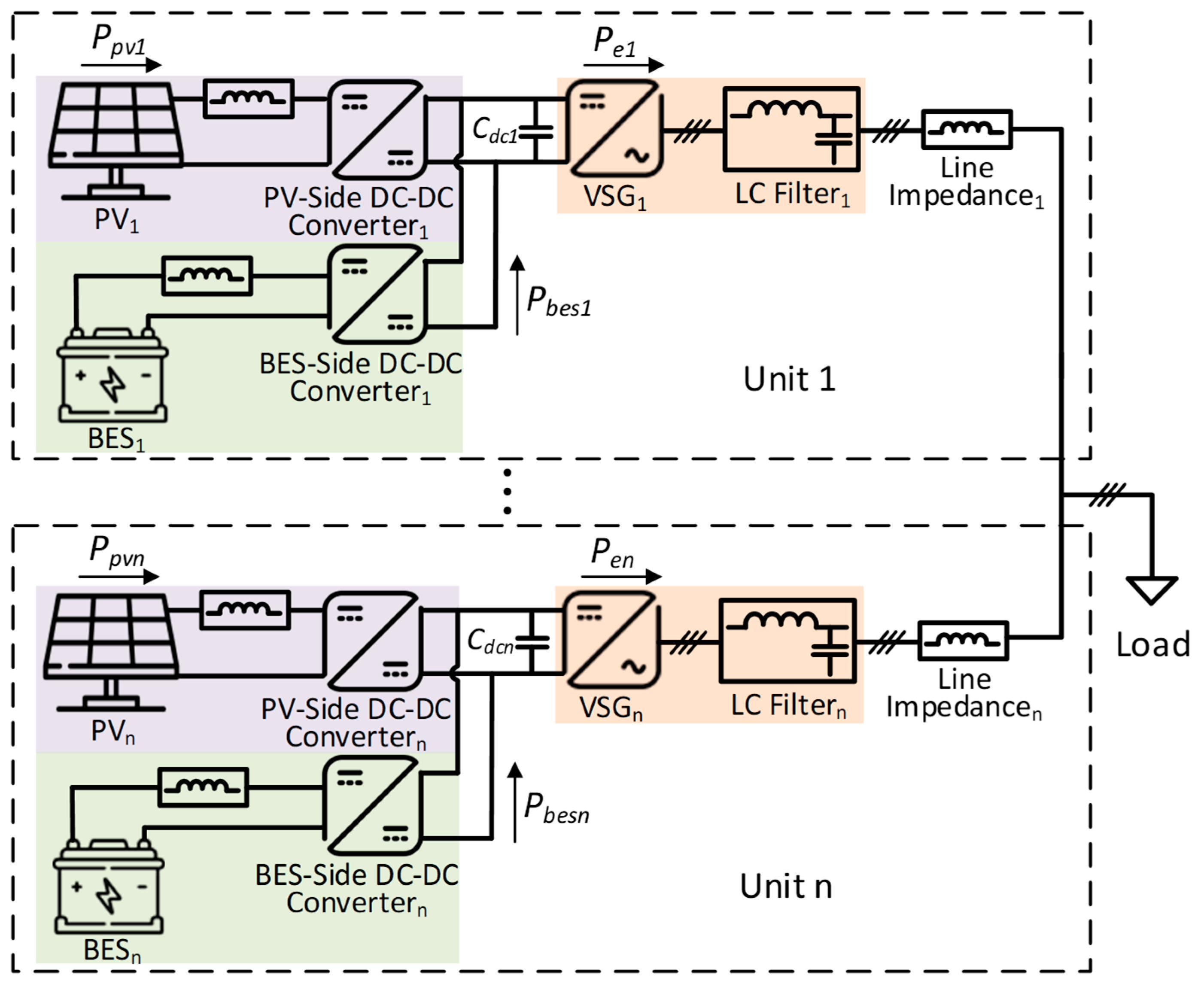
2. Typical Structure of a Paralleled PV-BES-VSG Power System

The structure of a paralleled PV-BES-VSG power system is depicted in Figure 1. The whole system includes multiple PV-BES-VSG units, each featuring both AC and DC sides. The DC-AC converter serves as the interface between these sides. A boost converter connects the PV module to the DC-link, while a half-bridge bidirectional DC-DC converter connects the BES to the DC-link. The VSG control is applied to the DC-AC converters, painted in orange. The PV-side DC-DC converter is equipped with the MPPT control, painted in purple. The BES-side DC-DC converter features a direct voltage control loop along with a current control loop, painted in green. The detailed control structures of these three power converters will be discussed in the following sections.

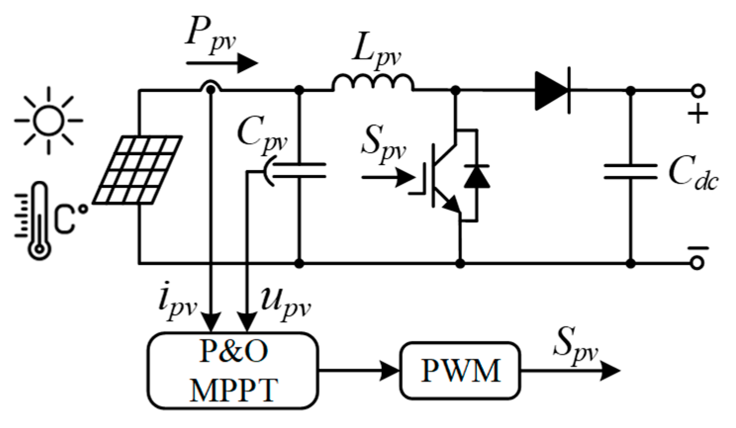
2.1. PV-Side DC-DC Converter

The structure of a boost converter connected to the output of PV modules is illustrated in Figure 2, where Lpv and Cpv represent the input filter inductor and capacitor; Cdc is the capacitor of the DC-link; Ppv, upv, and ipv represent the output power, voltage, and current of the PV module, respectively.
It is commonly known that the output power of the PV modules is influenced by both irradiance and temperature. To obtain maximum power production from PV modules, an MPPT control strategy is always adopted in PV systems. The Perturb and Observe (P&O) control scheme is among the most employed MPPT control strategies, owing to its simplicity. It is based on the power–voltage (P-V) characteristics of PV modules, which is illustrated in Figure 3 [44]. The P-V curve is like a hill and the peak of the curve is defined as the maximum power point (MPP). The P&O MPPT control scheme involves iteratively adjusting the operating point of the PV module by perturbing the operating voltage and then observing the corresponding variations in output power. By continuously monitoring the output power and then comparing it to previous values, the controller detects the direction of movement towards or away from the MPP. Using this information, the controller orchestrates adjustments to the operating point to facilitate convergence towards the MPP. This iterative process continues, ensuring that the PV system operates at or near the MPP, regardless of environmental dynamics such as fluctuations in irradiance or temperature. Therefore, this paper utilized the P&O MPPT control scheme to optimize the output power from PV modules. The output of the P&O MPPT control scheme determines the reference voltage for voltage control at the boost converter input. The boost converter regulates this voltage by adjusting the duty cycle, which is modulated using pulse width modulation (PWM) to generate the gating signal Spv for the switching device. Meanwhile, the inverter controller regulates the DC bus voltage.

2.2. BES-Side DC-DC Converter

The structure of a half-bridge bidirectional DC-DC converter fed by the BES is shown in Figure 4, where Lbes and Cbes represent the input filter inductor and capacitor; ibesref and ibes represent the reference and output currents of the BES; udcref and udc stand for the reference voltage and voltage of the DC link; Sbesu and Sbesd denote the gating signals for the upper and down switching devices, respectively; Pbes is the output power of the BES.
It is noteworthy that the equivalent electrical circuit was adopted to represent the dynamic behavior of the BES [45]. The equivalent electrical circuit model is depicted in Figure 5, where uocv stands for the open circuit voltage of the BES; the polarization resistance and capacitance of the BES are represented by R1 and C1; the internal resistance of the BES is indicated by R0.
The SoC is a crucial parameter for batteries and it can be estimated by various methods, including coulomb counting strategy, open circuit voltage measurement, impedance spectroscopy-based strategy, Kalman filter strategy, and neural network strategy. The coulomb counting strategy involves integrating the charge/discharge current over time [46]. The open circuit voltage measurement correlates the battery voltage with SoC based on established discharge curves [47]. The impedance spectroscopy-based strategy estimates the SoC by analyzing the battery’s impedance spectrum over a range of frequencies, providing insights into its electrochemical processes and internal characteristics [48]. The Kalman filter strategy offers high accuracy and robustness through a state-space model and recursive estimation [49]. The neural network strategy models the battery’s nonlinear characteristics for high accuracy, depending on training data and network design [50]. These methods are usually combined to achieve a more comprehensive and accurate estimation of SoC [51]. To simplify the computation, the coulomb counting strategy is employed, which can be given as follows:
S o C = S o C i n t 1 C b e s i b e s d t = S o C i n t 1 C b e s u b e s P b e s d t
where SoCint represents the initial SoC of the BES; the capacity and output voltage of the BES are represented by Cbes and ubes.
To enable bidirectional power flow between the DC link and the BES, a half-bridge bidirectional DC-DC converter was adopted. Structurally, it comprises two switching devices and corresponding diodes, configured in a manner to regulate the current flow direction. The BES-side DC-DC converter is controlled by a cascaded control system: an outer direct voltage loop along with an inner current loop. The direct voltage loop was adopted to keep the voltage of the DC-link at a rated value and gives the current references to the current loop, and then the current loop adjusts the BES current and generates the duty cycle. The PWM was adopted to modulate the duty cycle to generate the gating signals Sbesu and Sbesd to drive the upper and lower switching devices, respectively.

2.3. DC-AC Converter

Both PV and BES systems need to be connected to the AC side via a DC-AC converter. As RESs penetration increases, the power system may lack enough inertia to cope with the disturbances and the system stability will be challenged. To address this issue, the VSG control was introduced to enhance system stability.
The traditional topology of the VSG control is illustrated in Figure 6 [52], where uabc and uoabc stand for the terminal and output voltages of the converter, respectively; iabc, ioabc and iCabc denote the inductor current, converter output current, and capacitor current; the inductance and capacitance of the LC filter are represented by Lf and Cf; the line impedance between the converter and load is indicated by Zg.
The control scheme primarily consists of three components: a power synchronization part, an excitation loop, and a cascaded voltage and current loop. The power synchronization loop and excitation loop enable the DC-AC converter to mimic the behaviors of synchronous generators. The power synchronization loop yields
J d ω d t = P r e f P e ω g D ω ω g d θ d t = ω
where the moment of inertia and damping coefficient are represented by J and D; Pref and Pe are the reference and output active power of the converter; ωg and ω represent the rated and actual angular frequency.
The excitation loop describes the relationship between the reactive power and voltage, which can be expressed as follows:
u o d r e f = E 0 + k q k u U N u o d + Q r e f Q e
where ku denotes the voltage droop coefficient while kq denotes the integral coefficient; Qref and Qe represent the reference and output reactive power of the converter; UN is the rated voltage; E0 stands for the no-load electromotive force of the converter.
The cascaded voltage and current loops are used to modulate the converter’s output voltages and currents according to the voltage reference generated by the excitation loop and power synchronization loop.

3. Adaptive Control Strategy Considering SoC Balancing

Within the PV-BES-VSG system, BES needs to provide not only short-term inertia emulation but also long-term frequency regulation. For a power system with multiple BES, the coordination between them needs to be considered. Due to the different line impedances, initial SoCs, and the capacity of each BES, the SoCs of multiple BES are not always equal. Consequently, an unfavorable situation may occur where some BES with lower SoC might fail to supply adequate energy for primary frequency regulation and will be out of operation eventually, while some other BES with higher SoC are still available. In addition, it is well known that the degradation of BESs has a strong correlation with SoC. Therefore, it is pivotal to realize SoC balancing in a system with multiple BESs.
Assuming there is no power loss in the system, in accordance with the law of conservation of energy, the power within a paralleled PV-BES-VSG power system depicted in Figure 1 satisfies the following equation:
i = 1 n P p v i + i = 1 n P b e s i = P l o a d = i = 1 n P e i
where Ppvi, Pbesi, and Pei represent the output power of the PV-side DC-DC converter, the BES-side DC-DC converter, as well as the DC-AC converter of the ith PV-BES-VSG unit, respectively; Pload is the load power. Because the PV-side DC-DC converter is equipped with the MPPT control, the value of Ppvi is determined by the irradiance and temperature of each PV module.
According to the active power–frequency relationship presented in (2), it is obvious that the value of Pei is governed by the damping coefficient, moment of inertia, and the active power reference of each VSG. Since the VSG control inherits the oscillation characteristics of synchronous generators and the oscillations become more serious in a power system with multiple paralleled VSGs, an adaptive control scheme featuring a mutual damping term is presented in [18]. In this paper, to maintain the ability to mitigate the frequency and active power oscillation as well as simultaneously realize optimal, the method presented in [18] is also kept here, which can be expressed as follows:
i = 1 n J i d ω i d t = P r e f i ω i P e i ω i D i Δ ω i j Ω D m ω i ω j n
where Dm represents the mutual damping coefficient, the set of all adjacent VSGs is represented by Ω, and Ji and Di yield:
J i = J i 0 + k i ω i ω g d ω i d t D i = 2 ζ / X g ω g 3 E i U J i
where the ζ is set as 0.707; ki is the adaptive coefficient.
To further consider the capacity of the DC-side and realize SoC balancing, an additional adaptive term is applied to active power reference. When all the parameters are calculated in p.u. values, the ratio of output active power between two VSGs will be nearly proportional to the ratio of their active power references. Thus, to realize SoC balancing between multiple BES, the active power reference should be set larger if the SoC of the BES is higher, while the active power reference should be set smaller if the SoC of the BES is lower. If the SoC of a BES is close to 50%, its active power reference does not need to change a lot. Based on the requirements above, the adaptive SoC balancing term can be designed as follows:
P r e f i = a ( S o C i 0.5 ) 2 + b S o C i 0.5 a ( S o C i 0.5 ) 2 + b S o C i > 0.5
where a > 0, b > 0; a and b are the parameters to be designed.
To ensure the robustness of this method, when two BES with SoC of 20% and 80%, the ratio of active power references is set as 2%, which is based on prior testing and practical considerations. Based on this, the relationship between a and b can be obtained as
a = 10.67 b
The specific value of a can be arbitrary, as long as the proportional relationship between a and b is maintained. For ease of calculation, set the value of a as 10, and then the value of b can be calculated as 0.937. In summary, the adaptive term can be given as follows:
P r e f i = 10 ( S o C i 0.5 ) 2 + 0.937 S o C i 0.5 10 ( S o C i 0.5 ) 2 + 0.937 S o C i > 0.5
To better explain the relationship between the active power references and SoCs under the proposed adaptive SoC balancing term, Figure 7 shows the ratio of output active power references between two BES with varying SoCs. It is obvious that, when the SoC difference between the two BES increases, the ratio between the active power references increases accordingly. Moreover, the further the SoC is away from 50%, the faster the ratio between the active power references changes, which matches the design expectations.

4. Simulation Results

To evaluate the performance of the presented method for a paralleled PV-BES-VSG power system, a case study system with two paralleled units is conducted in Matlab/Simulink. Subscript 1 represents unit 1 and subscript 2 represents unit 2. Some main parameters of the case study system are listed in Table 1. Some detailed parameters can be found in our previous research [18].
Two conditions were chosen to evaluate the presented adaptive control scheme for a paralleled PV-BES-VSG power system. One is the irradiance variation, and the other one is the load step. In addition, the performance of the presented method was compared to that of the tradition VSG control method as well as the method without the SoC balancing mechanism presented in [18]. For clarity, the definition of the three methods is shown in Table 2. The traditional VSG control method with a fixed moment of inertia and damping coefficient is defined as Method 1. The method with an adaptive moment of inertia, damping coefficient, and mutual damping term—but without an SoC balancing mechanism—as presented in (5), is defined as Method 2. The adaptive control strategy with a SoC balancing mechanism presented in this study is defined as Method 3.

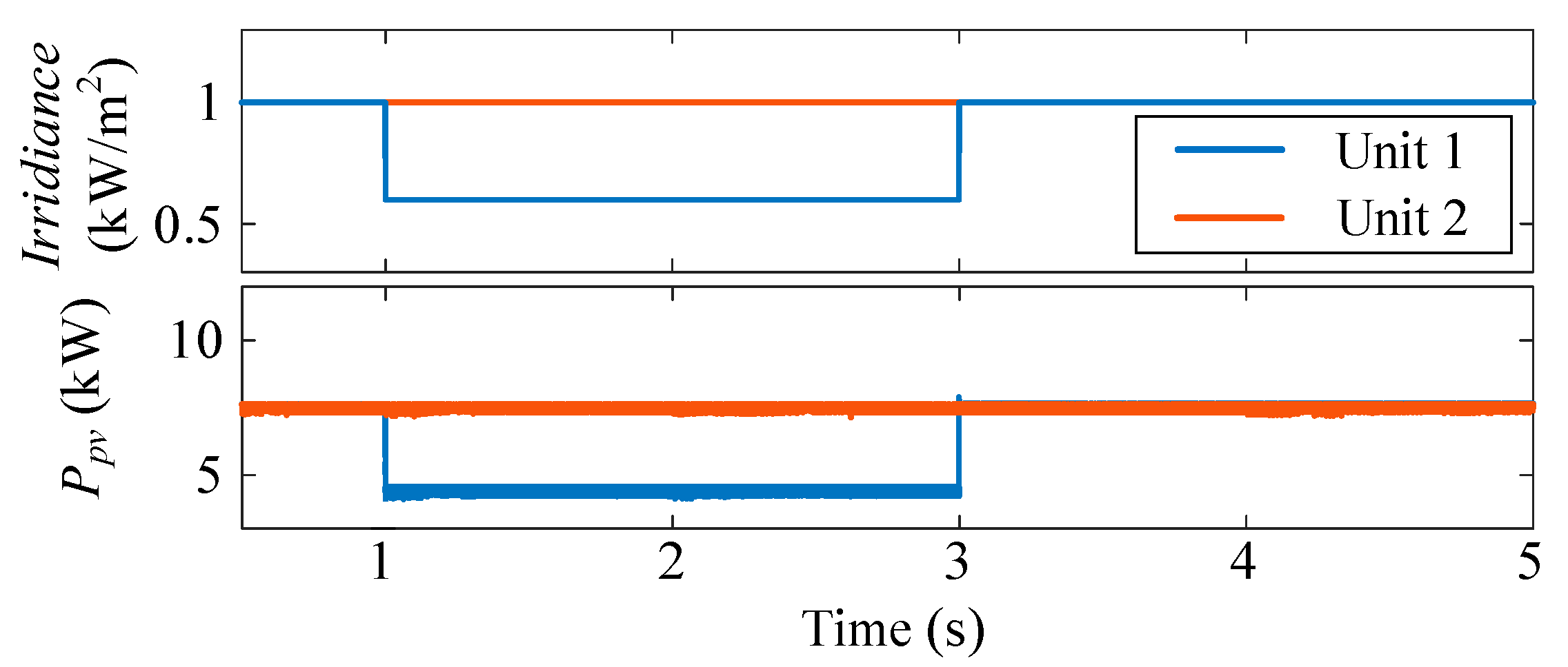
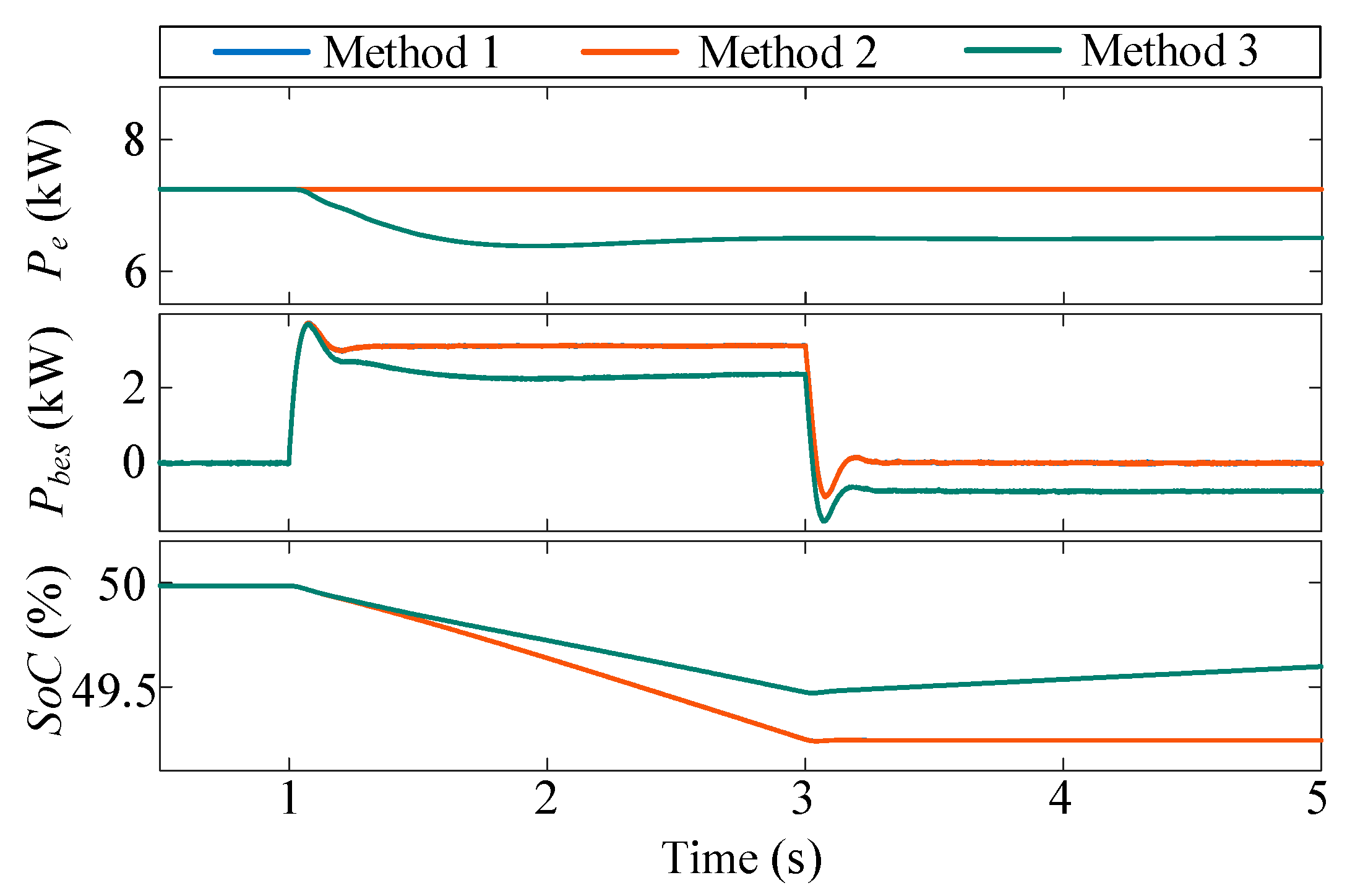
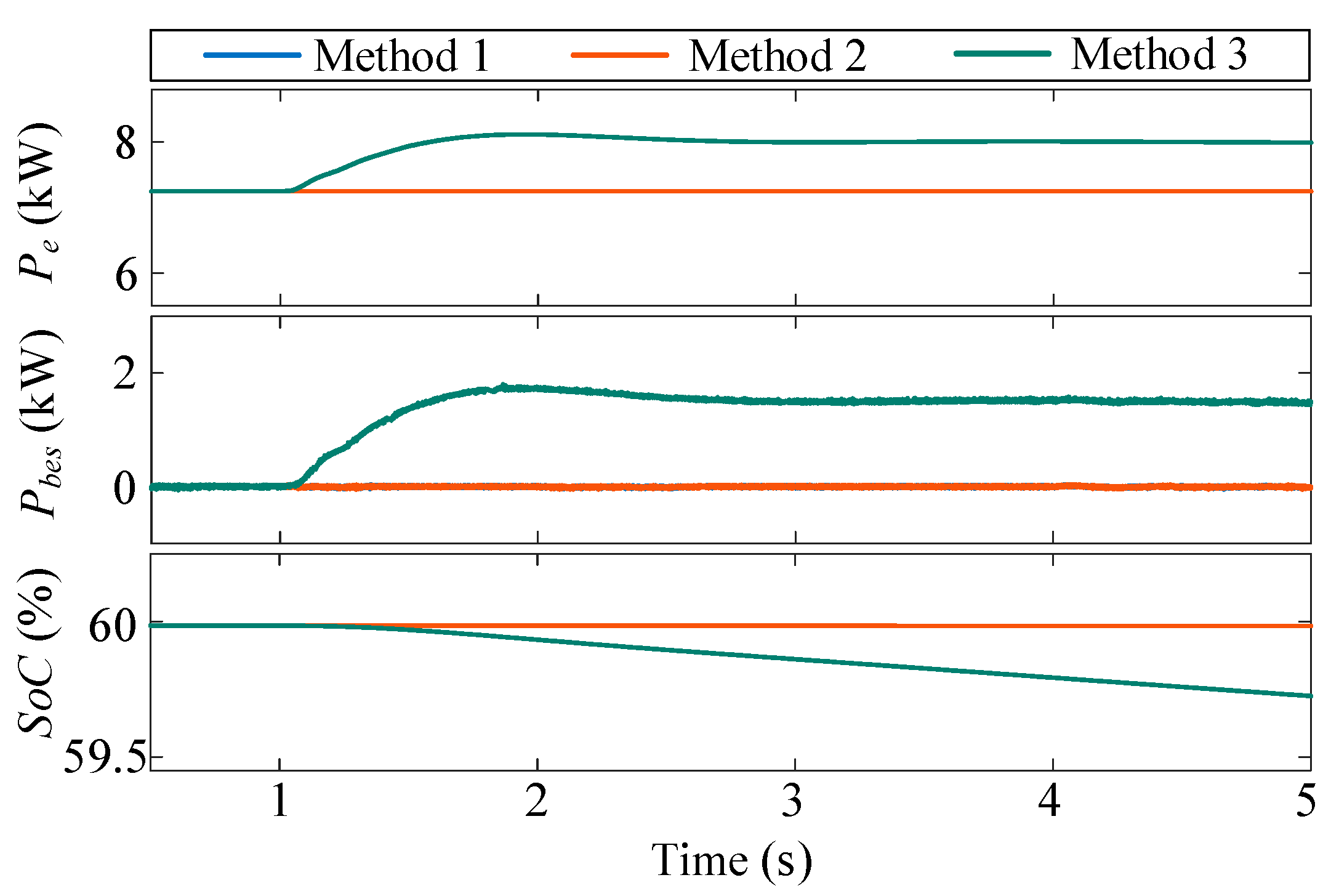
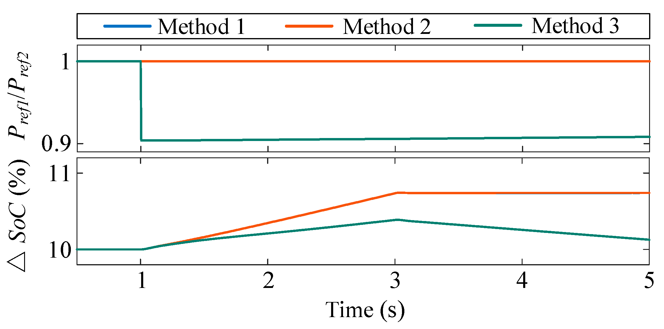
4.1. Irradiance Variation
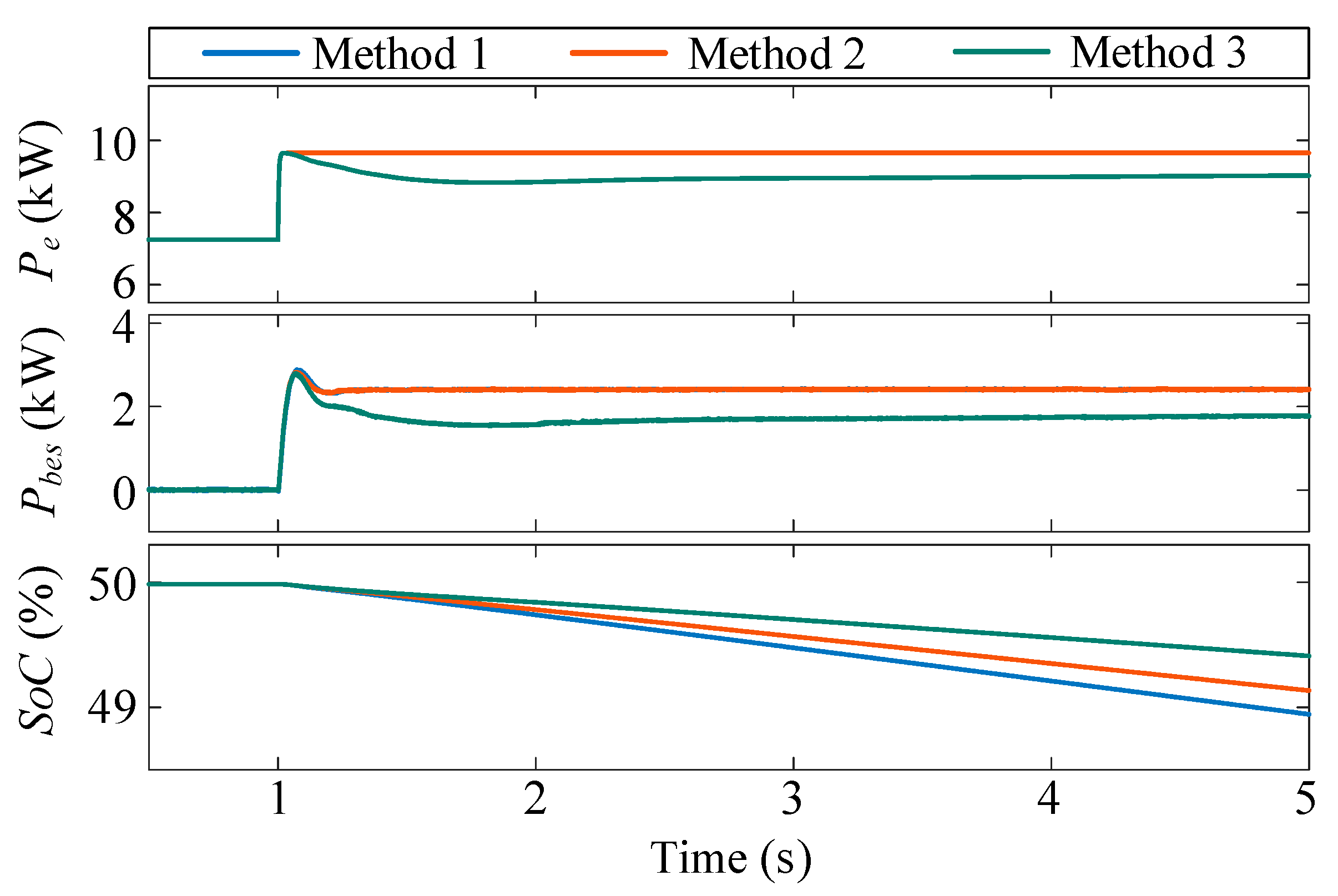
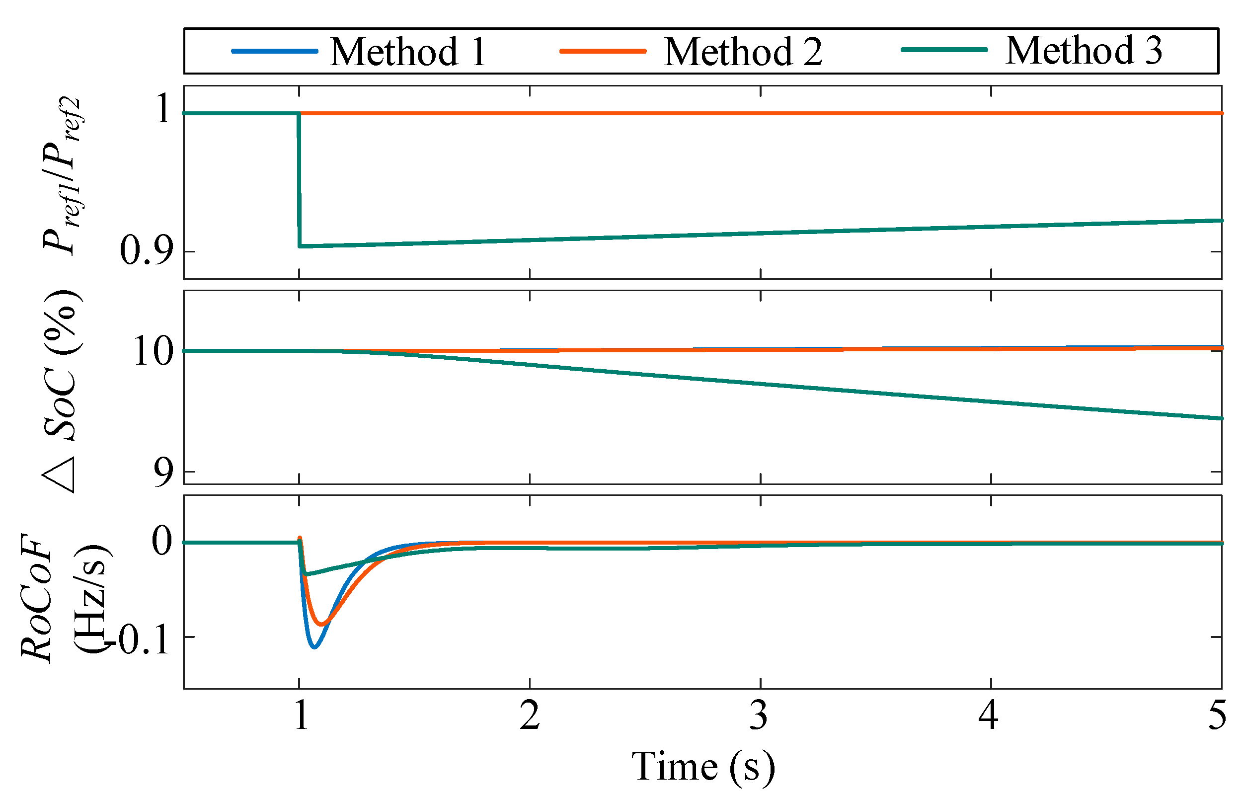
Because the MPPT control is implemented in the PV-side DC-DC converter, the change in irradiance will affect the output power of the PV modules. When there is a decrease in irradiance within unit 1 during 1 s to 3 s, the irradiance and output power of the PV modules are depicted in Figure 8. The output power of VSG1 as well as the output power and SoC of BES1 under the three control methods are depicted in Figure 9. The output power of VSG2 as well as the output power and SoC of BES2 under the three control methods are depicted in Figure 10. The reference active power of the VSGs and the difference between the SoCs under the three control methods are depicted in Figure 11.
As the irradiance of PV module 1 decreases, the output power of the PV part decreases, and the BES side generates more power to compensate for the power deficit and supply enough power to the load. For Method 1 and 2, due to the constant ratio between active power references of two VSGs, the power deficit resulting from the irradiance decrease in unit 1 is totally compensated by the BES in unit 1. However, the initial SoC of BES1 is less than that of BES2. If only BES1 discharges, the difference between the SoCs of the two BESsΔSoC increase further, leading to an unfavorable situation where BES1 is out of operation while BES2 is still at a higher SoC.
In contrast to Method 1 and 2, Method 3’s control incorporates a SoC balancing term. This results in a decrease in the ratio between the active power references of the two VSGs, Pref1/Pref2. Consequently, unit 1 supplies less power while unit 2 supplies more power. As a result, the power deficit resulting from the irradiance decrease in unit 1 can be shared by both BES1 and BES2, which can decrease SoC unbalancing compared to Method 1. After 3 s, although the irradiance increases back to 1 kW/m2, the SoCs of the two BES are still not the same. Thus, the ratio between active power references of two VSGs is not equal to 1 and the SoCs of the two BES change at different rates. As shown in Figure 11, in comparison to Method 1 and 2, the SoC difference between the two BES under Method 3 remains consistently smaller. At the end of the simulation, with the adoption of the SoC balancing term, the SoC difference decreases from 10.7% to 10.2%. Because the simulation time is only 5 s, the SoCs of the two VSGs have not achieved balancing. However, if the simulation time is extended, both the output power and SoCs of the two BES will reach the same value. The ratio between active power references of two VSGs will be equal to 1, and both VSGs’ output active power will be the same accordingly. Therefore, the presented control scheme can effectively decrease the difference of SoCs and realize the SoC balancing, thereby enhancing system reliability.

4.2. Load Step

The condition of a load step is also conducted under the two control methods. When a load step of 5 kW is added to the system at 1 s, the output power of VSG as well as the output power and SoC of BES, within two units under the three control methods, are depicted in Figure 12 and Figure 13, respectively. The reference active power of the VSGs, SoC differences, as well as the RoCoFs under the three control methods are depicted in Figure 14.
As a load step of 5 kW is added to the system, the output power from the BES side increases to provide power to the load. For Method 1 and 2, because the ratio between the active power references of the two VSGs is 1, the two VSGs share the power equally. The output active power of the BES in both units is around 2.5 kW, and the SoCs of the BES1 and BES2 change at the same rate. Nevertheless, the initial SoC of BES1 is less than that of BES2. As a result, the BES1 will be out of operation before BES2, which may deteriorate the reliability of the whole system.
However, when Method 3 is applied, the ratio between the active power references of the two VSGs Pref1/Pref2 is less than 1, causing unit 1 to provide less power compared to unit 2. Consequently, BES1 generates less power than that of BES2, the SoC of BES1 decreases at a lower rate, while the SoC of BES2 decreases at a higher rate. During the simulation time, the SoC of BES1 is always lower than that of BES2, but because the difference between SoC1 and SoC2 decreases, the ratio between active power references of two VSGs Pref1/Pref2 is always less than 1 but the value of Pref1/Pref2 increases. As shown in Figure 14, the SoC difference between two BES under the condition of Method 3 is always lower than that under the conditions of Methods 1 and 2. By employing the SoC balancing term, the SoC difference at the end of the simulation is reduced from 10% to 9.4%. Eventually, when the simulation time is extended, the two BESs will generate the same power and have the same SoC. The ratio between active power references of two VSGs Pref1/Pref2 will be 1 and the output active power Pe1 and Pe2 will be equal. In addition, as shown in Figure 14, under the control of Method 3, the maximum RoCoF is the smallest among the three methods. Therefore, the presented control method can slow down the change of frequency, ensuring system stability. Through the analysis above, the presented adaptive control strategy for a paralleled PV-BES-VSG power system can effectively obtain the SoC balancing and optimal operation of paralleled VSGs under the condition of a load step.

5. Conclusions

In this paper, an adaptive control strategy for a paralleled PV-BES-VSG power system was introduced to realize SoC balancing of battery energy storages and ensure optimal response of paralleled virtual synchronous generators at the same time. The typical topology and controllers of a power system with paralleled PV-BES-VSG units were discussed comprehensively. An adaptive term was applied to active power references based on a simple segmented quadratic function. Furthermore, the design guidelines for some key parameters were also provided, ensuring the sensitivity and robustness of the proposed method. Simulation results verified the effectiveness of the presented method.
Although the proposed method successfully addresses both SoC balancing and the optimal operation of paralleled virtual synchronous generators, several areas remain open for improvement and could be explored in future research. Specifically, this paper focused solely on the SoC balancing of battery energy storage systems. In practical applications, more complex hybrid energy storage systems—combining batteries with supercapacitors or other storage technologies—should be taken into account. Moreover, the integration of advanced artificial intelligence algorithms could further enhance the accuracy of SoC estimation and improve the overall control performance.

Author Contributions

Conceptualization, X.G.; methodology, X.G.; software, X.G.; validation, X.G.; writing—original draft preparation, X.G.; writing—review and editing, D.Z., A.A.-M. and F.B.; supervision, D.Z., A.A.-M. and F.B. All authors have read and agreed to the published version of the manuscript.

Funding

This research received no external funding.

Data Availability Statement

Data are contained within the article.

Conflicts of Interest

The authors declare no conflicts of interest.

References

  1. Blaabjerg, F.; Yang, Y.; Yang, D.; Wang, X. Distributed power-generation systems and protection. Proc. IEEE. 2017, 105, 1311–1331. [Google Scholar] [CrossRef]
  2. Paris Agreement, United Nations Framework Convention on Climate Change, Tech. Rep. Available online: https://unfccc.int/process-and-meetings/the-paris-agreement (accessed on 5 April 2024).
  3. Rocabert, J.; Luna, A.; Blaabjerg, F.; Rodriguez, P. Control of power converters in AC microgrids. IEEE Trans. Power Electron. 2012, 27, 4734–4749. [Google Scholar] [CrossRef]
  4. Fang, J.; Li, H.; Tang, Y.; Blaabjerg, F. Distributed power system virtual inertia implemented by grid-connected power converters. IEEE Trans. Power Electron. 2018, 33, 8488–8499. [Google Scholar] [CrossRef]
  5. Peng, Q.; Jiang, Q.; Yang, Y.; Liu, T.; Wang, H.; Blaabjerg, F. On the stability of power electronics-dominated systems: Challenges and potential solutions. IEEE Trans. Ind. Appl. 2019, 55, 7657–7670. [Google Scholar] [CrossRef]
  6. Zhong, Q.C.; Weiss, G. Synchronverters: Inverters that mimic synchronous generators. IEEE Trans. Ind. Electron. 2011, 58, 1259–1267. [Google Scholar] [CrossRef]
  7. Chen, M.; Zhou, D.; Blaabjerg, F. Active Power Oscillation Damping Based on Acceleration Control in Paralleled Virtual Synchronous Generators System. IEEE Trans. Power Electron. 2021, 36, 9501–9510. [Google Scholar] [CrossRef]
  8. Yu, Y.; Chaudhary, S.K.; Tinajero, G.D.A.; Xu, L.; Bakar, N.N.B.A.; Vasquez, J.C.; Guerrero, J.M. A reference-feedforward-based damping method for virtual synchronous generator control. IEEE Trans. Power Electron. 2022, 37, 7566–7571. [Google Scholar] [CrossRef]
  9. Li, M.; Yu, P.; Hu, W.; Wang, Y.; Shu, S.; Zhang, Z.; Blaabjerg, F. Phase feedforward damping control method for virtual synchronous generators. IEEE Trans. Power Electron. 2022, 37, 9790–9806. [Google Scholar] [CrossRef]
  10. Huang, L.; Xin, H.; Yuan, H.; Wang, G.; Ju, P. Damping effect of virtual synchronous machines provided by a dynamical virtual impedance. IEEE Trans. Energy Convers. 2020, 36, 570–573. [Google Scholar] [CrossRef]
  11. Li, M.; Huang, W.; Tai, N.; Yang, L.; Duan, D.; Ma, Z. A dual-adaptivity inertia control strategy for virtual synchronous generator. IEEE Trans. Power Syst. 2019, 35, 594–604. [Google Scholar] [CrossRef]
  12. Perez, F.; Damm, G.; Verrelli, C.M.; Ribeiro, P.F. Adaptive virtual inertia control for stable microgrid operation including ancillary services support. IEEE Trans. Contr. Syst. Technol. 2023, 31, 1552–1564. [Google Scholar] [CrossRef]
  13. Shintai, T.; Miura, Y.; Ise, T. Oscillation damping of a distributed generator using a virtual synchronous generator. IEEE Trans. Power Deliv. 2014, 29, 668–676. [Google Scholar] [CrossRef]
  14. Li, D.; Zhu, Q.; Lin, S.; Bian, X.Y. A self-adaptive inertia and damping combination control of VSG to support frequency stability. IEEE Trans. Energy Conver. 2016, 32, 397–398. [Google Scholar] [CrossRef]
  15. Wang, Z.; Meng, F.; Zhang, Y.; Wang, W.; Li, G.; Ge, J. Cooperative Adaptive Control of Multi-Parameter Based on Dual-Parallel Virtual Synchronous Generators System. IEEE Trans. Energy Convers. 2023, 38, 2396–2408. [Google Scholar] [CrossRef]
  16. Yu, Y.; Chaudhary, S.K.; Tinajero, G.D.A.; Xu, L.; Vasquez, J.C.; Guerrero, J.M. Active Damping for Dynamic Improvement of Multiple Grid-Tied Virtual Synchronous Generators. IEEE Trans. Ind. Electron. 2024, 71, 3673–3683. [Google Scholar] [CrossRef]
  17. Chen, S.; Sun, Y.; Han, H.; Shi, G.; Guan, Y.; Guerrero, J.M. Dynamic frequency performance analysis and improvement for parallel VSG systems considering virtual inertia and damping coefficient. IEEE J. Emerg. Sel. Top. Power Electron. 2023, 11, 478–489. [Google Scholar] [CrossRef]
  18. Gao, X.; Zhou, D.; Anvari-Moghaddam, A.; Blaabjerg, F. An adaptive control strategy with a mutual damping term for paralleled virtual synchronous generators system. Sustain. Energy Grids Netw. 2024, 38, 101308. [Google Scholar] [CrossRef]
  19. Kumar, A.W.; din Mufti, M.U.; Zargar, M.Y. Fuzzy based virtual inertia emulation in a multi-area wind penetrated power system using adaptive predictive control based flywheel storage. Sustain. Energy Technol. Assess. 2022, 53, 102515. [Google Scholar] [CrossRef]
  20. Ma, Y.; Cao, W.; Yang, L.; Wang, F.; Tolbert, L.M. Virtual synchronous generator control of full converter wind turbines with short-term energy storage. IEEE Trans. Ind. Electron. 2017, 64, 8821–8831. [Google Scholar] [CrossRef]
  21. Hasabelrasul, H.; Cai, Z.; Sun, L.; Suo, X.; Matraji, I. Two-stage converter standalone PV-battery system based on VSG control. IEEE Access 2022, 10, 39825–39832. [Google Scholar] [CrossRef]
  22. Liu, Y.; Wang, Y.; Wang, M.; Xu, Z.; Peng, Y.; Li, M. Coordinated VSG control of photovoltaic/battery system for maximum power output and grid supporting. IEEE J. Emerg. Sel. Top. Power Electron. 2022, 12, 301–309. [Google Scholar] [CrossRef]
  23. Sangwongwanich, A.; Yang, Y.; Blaabjerg, F. A sensorless power reserve control strategy for two-stage grid-connected PV systems. IEEE Trans. Ind. Electron. 2017, 32, 8559–8569. [Google Scholar] [CrossRef]
  24. Peng, Q.; Tang, Z.; Yang, Y.; Liu, T.; Blaabjerg, F. Event-triggering virtual inertia control of PV systems with power reserve. IEEE Trans. Ind. Appl. 2021, 57, 4059–4070. [Google Scholar] [CrossRef]
  25. Fang, J.; Tang, Y.; Li, H.; Li, X. A battery/ultracapacitor hybrid energy storage system for implementing the power management of virtual synchronous generators. IEEE Trans. Power Electron. 2018, 33, 2820–2824. [Google Scholar] [CrossRef]
  26. Sarojini, R.K.; Palanisamy, K.; Sanjeevikumar, P.; Nielsen, J.B.H. Inertia emulation control technique based frequency control of grid-connected single-phase rooftop photovoltaic system with battery and supercapacitor. IET Renew. Power Gen. 2020, 14, 1156–1163. [Google Scholar] [CrossRef]
  27. Quan, X.; Yu, R.; Zhao, X.; Lei, Y.; Chen, T.; Li, C.; Huang, A.Q. Photovoltaic synchronous generator: Architecture and control strategy for a grid-forming PV energy system. IEEE J. Emerg. Sel. Top. Power Electron. 2020, 8, 936–948. [Google Scholar] [CrossRef]
  28. Liu, J.; Hou, Y.; Guo, J.; Liu, X.; Liu, J. A Cost-Efficient Virtual Synchronous Generator System Based on Coordinated Photovoltaic and Supercapacitor. IEEE Trans. Power Electron. 2023, 38, 16219–16229. [Google Scholar] [CrossRef]
  29. Huang, Y.; Lv, Q.; Zhang, Z.; Dong, H. Virtual Synchronous Generator Adaptive Control of Energy Storage Power Station Based on Physical Constraints. Energy Eng. 2023, 120, 1401–1420. [Google Scholar] [CrossRef]
  30. Chen, Y.; Hu, W.; Jiang, W. Fuzzy-controlled energy storage VSG control strategy. In Proceedings of the 2022 International Conference on Artificial Intelligence and Computer Information Technology (AICIT), Yichang, China, 16–18 September 2022; pp. 1–4. [Google Scholar] [CrossRef]
  31. Mao, M.; Qian, C.; Ding, Y. Decentralized coordination power control for islanding microgrid based on PV/BES-VSG. CPSS Trans. Power Electron. Appl. 2018, 3, 14–24. [Google Scholar] [CrossRef]
  32. Liu, H.; Zhang, C.; Peng, X.; Zhang, S. Configuration of an energy storage system for primary frequency reserve and inertia response of the power grid. IEEE Access 2021, 9, 41965–41975. [Google Scholar] [CrossRef]
  33. Chen, J.; Liu, M.; Milano, F.; O’Donnell, T. Adaptive virtual synchronous generator considering converter and storage capacity limits. CSEE J. Power Energy Syst. 2022, 8, 580–590. [Google Scholar] [CrossRef]
  34. Li, C.; Coelho, E.A.A.; Dragicevic, T.; Guerrero, J.M.; Vasquez, J.C. Multiagent-based distributed state of charge balancing control for distributed energy storage units in AC microgrids. IEEE Trans. Ind. Appl. 2016, 53, 2369–2381. [Google Scholar] [CrossRef]
  35. Kumar, R.R.; Bharatiraja, C.; Udhayakumar, K.; Devakirubakaran, S.; Sekar, K.S.; Mihet-Popa, L. Advances in batteries, battery modeling, battery management system, battery thermal management, SoC, SOH, and charge/discharge characteristics in EV applications. IEEE Access 2023, 11, 105761–105809. [Google Scholar] [CrossRef]
  36. Fagundes, T.A.; Fuzato, G.H.F.; Ferreira, P.G.B.; Biczkowski, M.; Machado, R.Q. Fuzzy Controller for Energy Management and SoC Equalization in DC Microgrids Powered by Fuel Cell and Energy Storage Units. IEEE J. Emerg. Sel. Top. Ind. Electron. 2022, 3, 90–100. [Google Scholar] [CrossRef]
  37. Fagundes, T.A.; Fuzato, G.H.F.; Silva, L.J.R.; dos Santos Alonso, A.M.; Vasquez, J.C.; Guerrero, J.M.; Machado, R.Q. Battery Energy Storage Systems in Microgrids: A Review of SoC Balancing and Perspectives. IEEE Open J. Ind. Electron. Soc. 2024, 5, 961–992. [Google Scholar] [CrossRef]
  38. Diaz, N.L.; Luna, A.C.; Vasquez, J.C.; Guerrero, J.M. Centralized control architecture for coordination of distributed renewable generation and energy storage in islanded AC microgrids. IEEE Trans. Power Electron. 2016, 32, 5202–5213. [Google Scholar] [CrossRef]
  39. Buchinskiy, N.; Saitoh, H. SoC Balancing Mechanism to Improve Active Power Sharing Among Multiple ESS Units in Low-Inertia Power Systems. In Proceedings of the 2023 IEEE PES Innovative Smart Grid Technologies-Asia (ISGT Asia), Auckland, New Zealand, 21–24 November 2023; pp. 1–5. [Google Scholar] [CrossRef]
  40. Yang, Y.; Xu, D.; Ma, T.; Su, X. Adaptive cooperative terminal sliding mode control for distributed energy storage systems. IEEE Trans. Circuits Sys. I Regul. Pap. 2020, 68, 434–443. [Google Scholar] [CrossRef]
  41. Xu, D.; Tang, L.; Jiang, B.; Pan, T.; Liu, J.; Hua, W. Cooperative Adaptive Command Filtered Backstepping Control for EVs to UPS-Microgrid via Virtual Synchronous Generator. IEEE Trans. Cybern. 2024, 54, 5369–5380. [Google Scholar] [CrossRef]
  42. Wu, Q.; Chu, X.; Fan, Y.; Liu, L.; Sun, X. Consistency Algorithm-Based SOC Balancing Scheme of Retired Non-equal Capacity Lithium Battery in Virtual Synchronous Generator Controlled Microgrids. IEEE Access. 2025, 13, 9073–9088. [Google Scholar] [CrossRef]
  43. Chen, M.; Zhou, D.; Blaabjerg, F. A Decentralized Adaptive SOC Balancing Strategy in VSG-based Islanded Power System. In Proceedings of the 47th Annual Conference of the IEEE Industrial Electronics Society (IECON), Toronto, ON, Canada, 13–16 October 2021; pp. 1–6. [Google Scholar] [CrossRef]
  44. Yang, Y.; Kim, K.A.; Ding, T. Modeling and control of PV systems. In Control of Power Electronic Converters and Systems; Academic Press: Amsterdam, The Netherlands, 2018; pp. 243–268. [Google Scholar]
  45. Zhao, L.; Liu, Z.; Ji, G. Lithium-ion battery state of charge estimation with model parameters adaptation using H∞ extended Kalman filter. Control Eng. Pract. 2018, 81, 114–128. [Google Scholar] [CrossRef]
  46. Ng, K.S.; Moo, C.S.; Chen, Y.P.; Hsieh, Y.C. Enhanced coulomb counting method for estimating state-of-charge and state-of-health of lithium-ion batteries. Appl. Energy 2009, 86, 1506–1511. [Google Scholar] [CrossRef]
  47. Xing, Y.; He, W.; Pecht, M.; Tsui, K.L. State of charge estimation of lithium-ion batteries using the open-circuit voltage at various ambient temperatures. Appl. Energy 2014, 113, 106–115. [Google Scholar] [CrossRef]
  48. Huang, W.; Qahouq, J.A.A. An online battery impedance measurement method using DC–DC power converter control. IEEE Trans. Ind. Electron. 2014, 61, 5987–5995. [Google Scholar] [CrossRef]
  49. El Mejdoubi, A.; Oukaour, A.; Chaoui, H.; Gualous, H.; Sabor, J.; Slamani, Y. State-of-Charge and State-of-Health Lithium-Ion Batteries’ Diagnosis According to Surface Temperature Variation. IEEE Trans. Ind. Electron. 2016, 63, 2391–2402. [Google Scholar] [CrossRef]
  50. Dai, H.; Zhao, G.; Lin, M.; Wu, J.; Zheng, G. A Novel Estimation Method for the State of Health of Lithium-Ion Battery Using Prior Knowledge-Based Neural Network and Markov Chain. IEEE Trans. Ind. Electron. 2019, 66, 7706–7716. [Google Scholar] [CrossRef]
  51. Meng, J.; Ricco, M.; Luo, G.; Swierczynski, M.; Stroe, D.I.; Stroe, A.I.; Teodorescu, R. An overview and comparison of online implementable SOC estimation methods for lithium-ion battery. IEEE Trans. Ind. Appl. 2017, 54, 1583–1591. [Google Scholar] [CrossRef]
  52. Gao, X.; Zhou, D.; Anvari-Moghaddam, A.; Blaabjerg, F. Stability Analysis of Grid-Following and Grid-Forming Converters Based on State-Space Model. IEEE Trans. Ind. Appl. 2024, 60, 4910–4920. [Google Scholar] [CrossRef]
Figure 1. Typical structure of a paralleled PV-BES-VSG power system with n units.
Energies 18 02505 g001
Figure 2. Structure of a boost converter fed by PV modules.
Energies 18 02505 g002
Figure 3. Power–voltage (P-V) characteristics of PV modules.
Energies 18 02505 g003
Figure 4. Structure of a half-bridge bidirectional DC-DC converter.
Energies 18 02505 g004
Figure 5. Schematic of the equivalent electrical circuit model of a battery energy storage.
Energies 18 02505 g005
Figure 6. Traditional topology of a VSG-based DC-AC converter.
Energies 18 02505 g006
Figure 7. Ratio of output active power references between two BES with varying SoCs.
Energies 18 02505 g007
Figure 8. The irradiance variation and output power of PV modules.
Energies 18 02505 g008
Figure 9. Simulation results under irradiance variation of unit 1.
Energies 18 02505 g009
Figure 10. Simulation results under irradiance variation of unit 2.
Energies 18 02505 g010
Figure 11. The active power reference ratios and SoC differences under the three methods.
Energies 18 02505 g011
Figure 12. Simulation results under a load step of 5 kW of unit 1.
Energies 18 02505 g012
Figure 13. Simulation results under a load step of 5 kW of unit 2.
Energies 18 02505 g013
Figure 14. The active power reference ratios, SoC differences, and RoCoFs under three methods.
Energies 18 02505 g014
Table 1. Main parameters of the case study system.
DescriptionSymbolValue
Maximum power of PV modulesPPV1, PPV27.6 kW, 7.6 kW
Inductor and capacitor of PV-side DC-DC converterLpv, Cpv2 mH, 10 μF
Rated capacity of batteriesCbes1, Cbes21 Ah, 1 Ah
Inductor and capacitor of BES-side DC-DC converterLbes, Cbes2 mH, 10 μF
Initial SoCs of batteriesSoC1, SoC250%, 60%
DC-link capacitorCdc10 mF
Rated power of VSGsSVSG1, SVSG215.8 kVA, 15.8 kVA
LC filter of VSGsLf, Cf3 mH, 10 μF
Load powerPload15 kW
Table 2. Description of three method.
CaseDescription
Method 1Traditional VSG control method with fixed moment of inertia and damping coefficient [6], as shown in (2)
Method 2Adaptive moment of inertia and damping coefficient, with a mutual damping term [18], as shown in (5)
Method 3The adaptive control strategy with SoC balancing mechanism proposed in this study, as shown in (9)
Disclaimer/Publisher’s Note: The statements, opinions and data contained in all publications are solely those of the individual author(s) and contributor(s) and not of MDPI and/or the editor(s). MDPI and/or the editor(s) disclaim responsibility for any injury to people or property resulting from any ideas, methods, instructions or products referred to in the content.

